US5040069A - Electronic endoscope with a mask bump bonded to an image pick-up device - Google Patents
Electronic endoscope with a mask bump bonded to an image pick-up deviceDownload PDFInfo
- Publication number
- US5040069A US5040069AUS07/528,488US52848890AUS5040069AUS 5040069 AUS5040069 AUS 5040069AUS 52848890 AUS52848890 AUS 52848890AUS 5040069 AUS5040069 AUS 5040069A
- Authority
- US
- United States
- Prior art keywords
- image pickup
- substrate
- solid image
- pickup device
- electrodes
- Prior art date
- Legal status (The legal status is an assumption and is not a legal conclusion. Google has not performed a legal analysis and makes no representation as to the accuracy of the status listed.)
- Expired - Lifetime
Links
Images


Classifications
- A—HUMAN NECESSITIES
- A61—MEDICAL OR VETERINARY SCIENCE; HYGIENE
- A61B—DIAGNOSIS; SURGERY; IDENTIFICATION
- A61B1/00—Instruments for performing medical examinations of the interior of cavities or tubes of the body by visual or photographical inspection, e.g. endoscopes; Illuminating arrangements therefor
- A61B1/04—Instruments for performing medical examinations of the interior of cavities or tubes of the body by visual or photographical inspection, e.g. endoscopes; Illuminating arrangements therefor combined with photographic or television appliances
- A61B1/05—Instruments for performing medical examinations of the interior of cavities or tubes of the body by visual or photographical inspection, e.g. endoscopes; Illuminating arrangements therefor combined with photographic or television appliances characterised by the image sensor, e.g. camera, being in the distal end portion
- H—ELECTRICITY
- H04—ELECTRIC COMMUNICATION TECHNIQUE
- H04N—PICTORIAL COMMUNICATION, e.g. TELEVISION
- H04N23/00—Cameras or camera modules comprising electronic image sensors; Control thereof
- H04N23/50—Constructional details
- H04N23/54—Mounting of pick-up tubes, electronic image sensors, deviation or focusing coils
- H—ELECTRICITY
- H04—ELECTRIC COMMUNICATION TECHNIQUE
- H04N—PICTORIAL COMMUNICATION, e.g. TELEVISION
- H04N23/00—Cameras or camera modules comprising electronic image sensors; Control thereof
- H04N23/50—Constructional details
- H04N23/555—Constructional details for picking-up images in sites, inaccessible due to their dimensions or hazardous conditions, e.g. endoscopes or borescopes
Definitions
- This inventionrelates to a solid image-pickup assembly particularly suitable for use in medical and industrial electronic endoscopes.
- Electronic endoscopesgenerally have a solid image pickup device or imager such as a CCD fitted in the tip end of an insert portion to be introduced into a body.
- the solid image pickup deviceis usually supplied in the form of a solid image pickup assembly which has the image pickup device mounted on a wiring substrate and received in a package with a transparent protective glass window for transmission of incident light.
- the solid image pickup assemblyis fixedly mounted in an objective lens barrel.
- the wiring substrate for mounting the solid image pickup deviceis flat in shape and has predetermined wiring patterns formed thereon. The wiring portions on the substrate are connected with the electrode portions on the surface of the solid image pickup device by wire bonding means.
- the solid image pickup assembly to be incorporated into the insert portionhas to be small enough in size.
- solid image pickup deviceswhich are markedly improved in the degree of integration, more specifically, which are formed with ten thousands to hundred thousands picture elements on an extremely small chip of about 1-2 mm. The use of such a small device should contribute to the reduction in size of the solid image pickup assembly.
- the actual use of a small-size solid image pickup devicedoes not necessarily result in a corresponding reduction in size of the solid image pickup assembly as a whole, which has a triple-layer construction including a wiring substrate, a solid image pickup device mounted on the wiring substrate and protective glass covering the light receiving surface of the image pickup device.
- the electrodes which are formed on the front side of the solid image pickup devicehave to be connected to the electrodes on the wiring substrate by wire bonding means through interconnecting wires which are projected in an arch-like fashion. Therefore, it is necessary to provide a clearance of a certain width between the light receiving surface of the solid image pickup device and the protective glass.
- the present inventionhas as its object the provision of a compact small-size solid image pickup assembly particularly suitable for use in electronic endoscopes.
- a solid image pickup assemblywhich essentially includes: a substrate having a transparent window formed thereon by a masking member to define an image pickup region and wiring patterns formed on masked regions; and a solid image pickup device having the light receiving surface thereof disposed in face to face relation with the transparent window of the substrate and being connected with electrodes on the substrate by bump bonding.
- FIGS. 1 through 6show a first embodiment of the invention, of which,
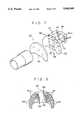
- FIG. 1is a sectional view of a tip end portion of the insert portion of an endoscope
- FIG. 2is an exploded perspective view of a solid image pickup assembly
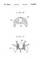
- FIG. 3is a sectional view taken on line III--III of FIG. 1;
- FIG. 4is an outer view of a substrate, taken from the back side thereof;
- FIG. 5is a plan view of a solid image pickup device
- FIG. 6is a diagrammatic illustration explanatory of the process of forming a solid image pickup assembly
- FIGS. 7 and 8show a second embodiment of the invention, of which,
- FIG. 7is an exploded perspective view of a solid image pickup assembly
- FIG. 8is a diagrammatic illustration of a thin film substrate construction
- FIGS. 9 to 11show a third embodiment of the invention, of which,
- FIG. 9is an exploded perspective view of a solid image pickup assembly
- FIG. 10is a plan view of the image forming side of a transparent substrate.
- FIG. 11is a plan view of the object side of the transparent substrate.
- FIG. 1Shown schematically in FIG. 1 is the construction of a tip end portion of an insert portion of an electronic endoscope, wherein indicated at 10 is a tip member secured to the fore end of the insert portion and provided with a through hole 11 for fittingly receiving therein an optical unit including inner and outer cylinders 12 and 13 of the lens barrel which supports an objective lens L.
- a solid image pickup assembly 14is securely attached to the inner end of the inner cylinder 12 of the lens barrel to serve as an image pickup means.
- the solid image pickup assembly 14has a construction as shown particularly in FIGS. 2 and 3.
- the reference 15indicates a substrate of insulating material such as ceramics or the like, which is centrally provided with a rectangular opening 16.
- the substrate 15is formed with predetermined wiring patterns 17 as shown in FIG. 4, each wiring pattern being connected to a wiring cable 18 at the outer peripheral marginal edge of the substrate 15 and having an electrode portion 17a in the vicinity of the center opening 16.
- a solid image pickup device 19is mounted on the rear side of the substrate 15. As clear from FIG. 5, the solid image pickup device 19 is centrally provided with a light receiving surface 19a between rows of a large number of electrodes 20. Facing the light receiving surface 19a toward the opening 16, the electrodes 20 of the solid image pickup device 19 are directly bonded to the electrode portions 17a of the wiring patterns 17 on the substrate 15.
- bumps of indium alloy, solder, conductive adhesive or the likeare used for bonding the electrodes 20 and 17a together.
- Bumpsare formed either on the electrodes 20 of the solid image pickup device 19 or on the electrode portions 17a of the substrate wiring patterns 17 (the electrodes 20 are formed to have a bump electrode structure in this particular embodiment).
- the solid image pickup device 19is positioned on the substrate 15 such that the bumps of the electrodes 20 are exactly in registration with the substrate electrodes 17a, and then the bumps are fused under heating condition to bond the electrodes 20 and 17a together by the so-called bump bonding.
- the solid image pickup device 19On the side away from the light receiving surface, the solid image pickup device 19 is provided with overflow drain electrodes, which are connected to the substrate 15 by wire bonding or alternatively by bump bonding if desired.
- the substrate 15is adapted to mount a buffer amplifier 21 on its rear side.
- the solid image pickup device 19 which has been mounted on the substrate 15 in this manneris covered in a sealed state under a sealing synthetic resin material such as epoxy resin or the like.
- a transparent protective member 23such as a sheet of flat optical glass or a transparent synthetic resin 23 is fitted in the center opening 16 through a sealing material 24 which seals off the peripheral edge portions of the transparent protective member 23. Consequently, the solid image pickup element 19 is retained in a sealed state.
- the substrate 15is formed substantially in a semi-circular shape and provided with lower extensions 15a at the opposite ends thereof to secure a broad substrate area for the wiring patterns 17 without interfering with instrument insertion channel T, light guide LG or other components which are built in or inserted into the insert portion of the endoscope.
- the solid image pickup device assembly 14is formed firstly by the use of a lead frame 25 as shown in FIG. 6, bonding a plural number of radially arranged lead members 25b on a rim portion 25a of the lead frame 25 to the respective wiring patterns on the substrate 15.
- the wiring cable 18is connected to the substrate 15.
- the use of the lead frame 25serves to simplify the wiring patterns 17 to be formed on the substrate 15, and therefore to reduce the surface area of the substrate 15. Consequently, it becomes possible to reduce the outer diameter of the solid image pickup assembly 14 while facilitating the connection of the substrate to the cable to a marked degree.
- the solid image pickup device 19is located in position on the rear side of the substrate 15, holding the light receiving surface 19a in alignment with the opening 16 and registering the respective electrodes 20 with the corresponding electrode portions of the wiring patterns 17.
- the thus registered electrodesare heated under pressure, whereupon the bump electrode portions are fused to bond the electrodes 20 and 17a together.
- the electrodes 20 and 17acan be connected directly to each other without resorting to the wire bonding means.
- a synthetic resin seal 22is applied to the rear side of the substrate 15 in such a manner as to cover the solid image pickup device 19, and the transparent protective member 23 is fitted in the opening 16 through the seal material 24 which stops the gap around the protective member 23, thereby retaining the solid image pickup device 19 in sealed state for protection while preventing electric disconnections between the electrodes 20 and 17a.
- the rim portion 25a of the lead frame 25is cut off, and the outer free ends of the lead portions 25b are folded rearward.
- the solid image pickup device assembly 14 thus formedis mounted within the tip section 10 by securely fixing the front side of the substrate 15 to the inner end of the barrel 13 of the objective lens L with use of bonding or other suitable fixation means, and connecting a cable to the ends of the lead portions 25b.
- the solid image pickup device 19is directly connected to the substrate 15 across the center opening 16 by bump bonding without using interconnecting wires, so that the solid image pickup assembly 14 can be formed in a thickness substantially corresponding to the combined thickness of the substrate 15 and the solid image pickup device 19. Accordingly, the dimensions including the thickness of the solid image pickup assembly 14 can be reduced markedly as compared with the conventional counterpart of the triple-layer construction which is composed of a substrate, a solid image pickup device and a transparent protective member and which is required to provide a clearance between the solid image pickup device and the transparent protective member to accommodate the interconnecting wires which are projected from the solid image pickup device as a result of wire bonding.
- the bump bonding of the substrate 15 and solid image pickup device 19requires only a minimum substrate surface area which is necessary for forming the wiring patterns 17 and therefore permits to reduce also the areal dimensions of the substrate 15. Consequently, it becomes possible to reduce the diametral dimensions of the components contained in the insert portion and the diameter of the insert portion itself.
- an angle portion and a flexible portionare successively connected to the rigid tip member 10 at the distal end of the insert portion of the endoscope.
- the rigid portion R which cannot bend itself along the path of insertionis extended as far as the inner end of a rigid sleeve member 10a which is provided in such a manner as to circumvent the solid image pickup assembly 14 for protection thereof.
- the reduction in thickness of the solid image pickup assembly 14makes it possible to reduce the axial length of the sleeve 10a and thus the dimensions of the rigid portion R.
- the reduction in length of the rigid portion Reven if it is smaller than 1 mm, has an extremely great importance in manipulation of the endoscope, for example, for facilitating the observation of an infected area when inserted into a narrow bronchus or the like.
- the light receiving surface of the solid image pickup device 19has to be confined only to the light which contributes to the imaging and shielded from other unnecessary light.
- the picture qualityis degraded by blooming unless the storage areas are completely shielded from light. Accordingly, it is necessary to provide a shielding means which prevents incidence of unnecessary light on the light receiving surface of the solid image pickup device 19.
- the solid image pickup device 19which is mounted on the substrate 15 substantially in an intimately contacting relation with the rear side of the substrate 15 is completely shielded from light except the areas corresponding to the opening 16. It follows that, when the opening 16 is formed in an appropriate shape, it functions as a masking plate for preventing incidence of unnecessary light on the solid image pickup device 19.
- FIGS. 7 and 8illustrate a second embodiment of the invention, in which, as seen particularly in FIG. 7, a solid image pickup assembly 101 is constituted by a transparent support plate 102 of optical glass or other material, a flexible thin film substrate 103 consisting of a resin film or the like and bonded to one side of the support plate 102, and a solid image pickup device 104 mounted on the thin film substrate 103.
- the thin film substrate 103blocks light except in the area of a rectangular opening 105 which is provided centrally in the substrate 103.
- the thin film substrate 103is provided with a plural number of flap portions 106 which are extended radially outward of the peripheral edge of the transparent support plate 102 and folded backward.
- wiring patterns 107which are formed on the surface of the thin film substrate 103 are extended onto the folded flap portions 106 and connected to cables 111.
- the wiring patterns 107are provided with electrode portions 109.
- the solid image pickup device 104is mounted on the rear side of the thin film substrate 103 with the wiring patterns 107, facing the light receiving surface 104a toward the opening 105. Electrodes 110 which are provided on the part of the solid image pickup device 104 are registered with and connected to the electrode portions 109 by bump bonding. The flap portions 106 of the thin film substrate 103 are folded back toward the solid image pickup device 104 and connected to cables 111.
- the thin film substrate 103likewise functions as a masking member for preventing incidence of unnecessary light on the solid image pickup device 104.
- FIGS. 9 to 11there is shown a third preferred embodiment of the invention, which employs a transparent substrate 201 of a flat glass sheet in the insert portion of an electronic endoscope.
- a masking layer 202is formed on one side of the transparent substrate 201 to define light-blocking areas as indicated by hatching in FIG. 10, leaving a rectangular light transmitting window 203 in a center portion of the transparent substrate 201.
- a plural number of wiring patterns 204are formed on the other side of the substrate 201 as shown in FIG. 11, in the areas which are masked by the masking layer 202.
- a flat flexible wiring board 205is connected to the respective wiring patterns 204 to lead them out to a suitable position.
- the wiring patterns 204are provided with electrode portions 206 in the same manner as in the foregoing embodiments.
- the solid image pickup device 207is bonded through bumps to the rear side of the transparent substrate 201 bearing the wiring patterns 204, with the light receiving surface 207a in alignment with the window 203 and with the electrodes 208 in registration with the electrode portions 206 on the part of the transparent substrate 201.
Landscapes
- Health & Medical Sciences (AREA)
- Life Sciences & Earth Sciences (AREA)
- Engineering & Computer Science (AREA)
- Surgery (AREA)
- Multimedia (AREA)
- Signal Processing (AREA)
- Radiology & Medical Imaging (AREA)
- Heart & Thoracic Surgery (AREA)
- Optics & Photonics (AREA)
- Pathology (AREA)
- Biophysics (AREA)
- Physics & Mathematics (AREA)
- Biomedical Technology (AREA)
- Nuclear Medicine, Radiotherapy & Molecular Imaging (AREA)
- Medical Informatics (AREA)
- Molecular Biology (AREA)
- Animal Behavior & Ethology (AREA)
- General Health & Medical Sciences (AREA)
- Public Health (AREA)
- Veterinary Medicine (AREA)
- Endoscopes (AREA)
- Solid State Image Pick-Up Elements (AREA)
Abstract
Description
1. Field of the Invention
This invention relates to a solid image-pickup assembly particularly suitable for use in medical and industrial electronic endoscopes.
2. Description of the Prior Art
Electronic endoscopes generally have a solid image pickup device or imager such as a CCD fitted in the tip end of an insert portion to be introduced into a body. The solid image pickup device is usually supplied in the form of a solid image pickup assembly which has the image pickup device mounted on a wiring substrate and received in a package with a transparent protective glass window for transmission of incident light. The solid image pickup assembly is fixedly mounted in an objective lens barrel. The wiring substrate for mounting the solid image pickup device is flat in shape and has predetermined wiring patterns formed thereon. The wiring portions on the substrate are connected with the electrode portions on the surface of the solid image pickup device by wire bonding means.
In the case of a bronchoscope to be inserted into the bronchus, for example, its insert portion is required to be as small as possible in diameter and to contain a rigid portion of as small a length as possible. In order to meet these requirements, the solid image pickup assembly to be incorporated into the insert portion has to be small enough in size. Recently, there have been developed solid image pickup devices which are markedly improved in the degree of integration, more specifically, which are formed with ten thousands to hundred thousands picture elements on an extremely small chip of about 1-2 mm. The use of such a small device should contribute to the reduction in size of the solid image pickup assembly.
However, as mentioned hereinbefore, the actual use of a small-size solid image pickup device does not necessarily result in a corresponding reduction in size of the solid image pickup assembly as a whole, which has a triple-layer construction including a wiring substrate, a solid image pickup device mounted on the wiring substrate and protective glass covering the light receiving surface of the image pickup device. In addition, the electrodes which are formed on the front side of the solid image pickup device have to be connected to the electrodes on the wiring substrate by wire bonding means through interconnecting wires which are projected in an arch-like fashion. Therefore, it is necessary to provide a clearance of a certain width between the light receiving surface of the solid image pickup device and the protective glass. This results in an increased thickness of the solid image pickup assembly as a whole, making it difficult to shorten the length of the rigid portion at the tip end of the insert portion. Besides, the wire bonding itself requires to extend the interconnecting wires over a certain distance in a direction parallel with the face of the image pickup device, barring the reduction of the wiring substrate dimensions as well as the reduction of the diameter of the insert portion.
With the foregoing situations in view, the present invention has as its object the provision of a compact small-size solid image pickup assembly particularly suitable for use in electronic endoscopes.
In accordance with the present invention, for achieving the above-stated object, there is provided a solid image pickup assembly which essentially includes: a substrate having a transparent window formed thereon by a masking member to define an image pickup region and wiring patterns formed on masked regions; and a solid image pickup device having the light receiving surface thereof disposed in face to face relation with the transparent window of the substrate and being connected with electrodes on the substrate by bump bonding.
The above and other objects, features and advantages of the invention will become apparent from the following description and the appended claims, taken in conjunction with the preferred embodiments shown in the accompanying drawings, which are given for the purpose of illustration only and, needless to say, should not be construed as limitative of the invention.
In the accompanying drawings:
FIGS. 1 through 6 show a first embodiment of the invention, of which,
FIG. 1 is a sectional view of a tip end portion of the insert portion of an endoscope;
FIG. 2 is an exploded perspective view of a solid image pickup assembly;
FIG. 3 is a sectional view taken on line III--III of FIG. 1;
FIG. 4 is an outer view of a substrate, taken from the back side thereof;
FIG. 5 is a plan view of a solid image pickup device; and
FIG. 6 is a diagrammatic illustration explanatory of the process of forming a solid image pickup assembly;
FIGS. 7 and 8 show a second embodiment of the invention, of which,
FIG. 7 is an exploded perspective view of a solid image pickup assembly; and
FIG. 8 is a diagrammatic illustration of a thin film substrate construction; and
FIGS. 9 to 11 show a third embodiment of the invention, of which,
FIG. 9 is an exploded perspective view of a solid image pickup assembly;
FIG. 10 is a plan view of the image forming side of a transparent substrate; and
FIG. 11 is a plan view of the object side of the transparent substrate.
Hereafter, the invention is described more particularly by way of the preferred embodiments shown in the drawings.
Shown schematically in FIG. 1 is the construction of a tip end portion of an insert portion of an electronic endoscope, wherein indicated at 10 is a tip member secured to the fore end of the insert portion and provided with athrough hole 11 for fittingly receiving therein an optical unit including inner andouter cylinders image pickup assembly 14 is securely attached to the inner end of theinner cylinder 12 of the lens barrel to serve as an image pickup means.
The solidimage pickup assembly 14 has a construction as shown particularly in FIGS. 2 and 3. In these figures, thereference 15 indicates a substrate of insulating material such as ceramics or the like, which is centrally provided with arectangular opening 16. On the rear side, thesubstrate 15 is formed withpredetermined wiring patterns 17 as shown in FIG. 4, each wiring pattern being connected to awiring cable 18 at the outer peripheral marginal edge of thesubstrate 15 and having anelectrode portion 17a in the vicinity of the center opening 16.
A solidimage pickup device 19 is mounted on the rear side of thesubstrate 15. As clear from FIG. 5, the solidimage pickup device 19 is centrally provided with alight receiving surface 19a between rows of a large number ofelectrodes 20. Facing thelight receiving surface 19a toward theopening 16, theelectrodes 20 of the solidimage pickup device 19 are directly bonded to theelectrode portions 17a of thewiring patterns 17 on thesubstrate 15.
For bonding theelectrodes electrodes 20 of the solidimage pickup device 19 or on theelectrode portions 17a of the substrate wiring patterns 17 (theelectrodes 20 are formed to have a bump electrode structure in this particular embodiment). The solidimage pickup device 19 is positioned on thesubstrate 15 such that the bumps of theelectrodes 20 are exactly in registration with thesubstrate electrodes 17a, and then the bumps are fused under heating condition to bond theelectrodes
On the side away from the light receiving surface, the solidimage pickup device 19 is provided with overflow drain electrodes, which are connected to thesubstrate 15 by wire bonding or alternatively by bump bonding if desired. Thesubstrate 15 is adapted to mount abuffer amplifier 21 on its rear side.
The solidimage pickup device 19 which has been mounted on thesubstrate 15 in this manner is covered in a sealed state under a sealing synthetic resin material such as epoxy resin or the like. For the purpose of protecting thelight receiving surface 19a of the solidimage pickup device 19, a transparentprotective member 23 such as a sheet of flat optical glass or a transparentsynthetic resin 23 is fitted in the center opening 16 through a sealingmaterial 24 which seals off the peripheral edge portions of the transparentprotective member 23. Consequently, the solidimage pickup element 19 is retained in a sealed state.
Thesubstrate 15 is formed substantially in a semi-circular shape and provided withlower extensions 15a at the opposite ends thereof to secure a broad substrate area for thewiring patterns 17 without interfering with instrument insertion channel T, light guide LG or other components which are built in or inserted into the insert portion of the endoscope.
In the present embodiment with the above-described arrangements, the solid imagepickup device assembly 14 is formed firstly by the use of alead frame 25 as shown in FIG. 6, bonding a plural number of radially arrangedlead members 25b on arim portion 25a of thelead frame 25 to the respective wiring patterns on thesubstrate 15. By so doing, thewiring cable 18 is connected to thesubstrate 15. In this instance, the use of thelead frame 25 serves to simplify thewiring patterns 17 to be formed on thesubstrate 15, and therefore to reduce the surface area of thesubstrate 15. Consequently, it becomes possible to reduce the outer diameter of the solidimage pickup assembly 14 while facilitating the connection of the substrate to the cable to a marked degree.
In the next place, the solidimage pickup device 19 is located in position on the rear side of thesubstrate 15, holding thelight receiving surface 19a in alignment with theopening 16 and registering therespective electrodes 20 with the corresponding electrode portions of thewiring patterns 17. The thus registered electrodes are heated under pressure, whereupon the bump electrode portions are fused to bond theelectrodes image pickup device 19 is normally provided with theelectrodes 20 on the front side which faces thewiring patterns 17 on the rear side of thesubstrate 15, theelectrodes
After completing the connections between the substrate and the solidimage pickup device 19, asynthetic resin seal 22 is applied to the rear side of thesubstrate 15 in such a manner as to cover the solidimage pickup device 19, and the transparentprotective member 23 is fitted in theopening 16 through theseal material 24 which stops the gap around theprotective member 23, thereby retaining the solidimage pickup device 19 in sealed state for protection while preventing electric disconnections between theelectrodes
Nextly, therim portion 25a of thelead frame 25 is cut off, and the outer free ends of thelead portions 25b are folded rearward. The solid imagepickup device assembly 14 thus formed is mounted within thetip section 10 by securely fixing the front side of thesubstrate 15 to the inner end of thebarrel 13 of the objective lens L with use of bonding or other suitable fixation means, and connecting a cable to the ends of thelead portions 25b.
In this manner, the solidimage pickup device 19 is directly connected to thesubstrate 15 across thecenter opening 16 by bump bonding without using interconnecting wires, so that the solidimage pickup assembly 14 can be formed in a thickness substantially corresponding to the combined thickness of thesubstrate 15 and the solidimage pickup device 19. Accordingly, the dimensions including the thickness of the solidimage pickup assembly 14 can be reduced markedly as compared with the conventional counterpart of the triple-layer construction which is composed of a substrate, a solid image pickup device and a transparent protective member and which is required to provide a clearance between the solid image pickup device and the transparent protective member to accommodate the interconnecting wires which are projected from the solid image pickup device as a result of wire bonding. In addition, in contrast to the wire bonding which needs a certain extent of extra spaces on the substrate, the bump bonding of thesubstrate 15 and solidimage pickup device 19 requires only a minimum substrate surface area which is necessary for forming thewiring patterns 17 and therefore permits to reduce also the areal dimensions of thesubstrate 15. Consequently, it becomes possible to reduce the diametral dimensions of the components contained in the insert portion and the diameter of the insert portion itself.
As is well known in the art, an angle portion and a flexible portion are successively connected to therigid tip member 10 at the distal end of the insert portion of the endoscope. Namely, the rigid portion R which cannot bend itself along the path of insertion is extended as far as the inner end of arigid sleeve member 10a which is provided in such a manner as to circumvent the solidimage pickup assembly 14 for protection thereof. The reduction in thickness of the solidimage pickup assembly 14 makes it possible to reduce the axial length of thesleeve 10a and thus the dimensions of the rigid portion R. Especially in case of an endoscope, the reduction in length of the rigid portion R, even if it is smaller than 1 mm, has an extremely great importance in manipulation of the endoscope, for example, for facilitating the observation of an infected area when inserted into a narrow bronchus or the like.
Further, in order to obtain images of satisfactory quality from the solidimage pickup device 19, the light receiving surface of the solidimage pickup device 19 has to be confined only to the light which contributes to the imaging and shielded from other unnecessary light. For example, in case of a frame transfer type CCD which is constituted by image and storage areas, the picture quality is degraded by blooming unless the storage areas are completely shielded from light. Accordingly, it is necessary to provide a shielding means which prevents incidence of unnecessary light on the light receiving surface of the solidimage pickup device 19.
In this regard, the solidimage pickup device 19 which is mounted on thesubstrate 15 substantially in an intimately contacting relation with the rear side of thesubstrate 15 is completely shielded from light except the areas corresponding to theopening 16. It follows that, when theopening 16 is formed in an appropriate shape, it functions as a masking plate for preventing incidence of unnecessary light on the solidimage pickup device 19.
FIGS. 7 and 8 illustrate a second embodiment of the invention, in which, as seen particularly in FIG. 7, a solidimage pickup assembly 101 is constituted by atransparent support plate 102 of optical glass or other material, a flexiblethin film substrate 103 consisting of a resin film or the like and bonded to one side of thesupport plate 102, and a solidimage pickup device 104 mounted on thethin film substrate 103. Thethin film substrate 103 blocks light except in the area of arectangular opening 105 which is provided centrally in thesubstrate 103. Further, thethin film substrate 103 is provided with a plural number offlap portions 106 which are extended radially outward of the peripheral edge of thetransparent support plate 102 and folded backward.
As shown in FIG. 8,wiring patterns 107 which are formed on the surface of thethin film substrate 103 are extended onto the foldedflap portions 106 and connected tocables 111. Thewiring patterns 107 are provided withelectrode portions 109.
The solidimage pickup device 104 is mounted on the rear side of thethin film substrate 103 with thewiring patterns 107, facing the light receiving surface 104a toward theopening 105.Electrodes 110 which are provided on the part of the solidimage pickup device 104 are registered with and connected to theelectrode portions 109 by bump bonding. Theflap portions 106 of thethin film substrate 103 are folded back toward the solidimage pickup device 104 and connected tocables 111.
This arrangements permit to make the solid image pickup assembly more compact and smaller in size. Thethin film substrate 103 likewise functions as a masking member for preventing incidence of unnecessary light on the solidimage pickup device 104.
Referring to FIGS. 9 to 11, there is shown a third preferred embodiment of the invention, which employs atransparent substrate 201 of a flat glass sheet in the insert portion of an electronic endoscope. Amasking layer 202 is formed on one side of thetransparent substrate 201 to define light-blocking areas as indicated by hatching in FIG. 10, leaving a rectangularlight transmitting window 203 in a center portion of thetransparent substrate 201.
A plural number ofwiring patterns 204 are formed on the other side of thesubstrate 201 as shown in FIG. 11, in the areas which are masked by themasking layer 202. A flatflexible wiring board 205 is connected to therespective wiring patterns 204 to lead them out to a suitable position. Thewiring patterns 204 are provided withelectrode portions 206 in the same manner as in the foregoing embodiments.
The solidimage pickup device 207 is bonded through bumps to the rear side of thetransparent substrate 201 bearing thewiring patterns 204, with thelight receiving surface 207a in alignment with thewindow 203 and with theelectrodes 208 in registration with theelectrode portions 206 on the part of thetransparent substrate 201.
This arrangement is substantially the same as the above-described first and second embodiments in operation and resulting effects.
Claims (5)
1. A solid image pickup assembly for use in an electronic endoscope comprising:
a solid image pickup device having an image pickup area and electrodes on the same surface;
a substrate having a masking means defining an image pickup area in the form of a light transmitting transparent window;
said masking means bearing a wiring pattern and electrodes on a surface opposite to said image pickup device; and
at least one electrode of said image pickup device and at least one respective electrode of said masking means being bump bonded to one another.
2. A solid image pickup assembly as defined in claim 1, wherein said substrate is composed of an opaque substrate sheet having an opening in said image pickup area and a transparent sheet fitted in said opening.
3. A solid image pickup assembly as defined in claim 1, wherein said substrate is composed of a transparent support member and a thin film substrate member adhered to said transparent support member.
4. A solid image pickup assembly as defined in claim 1, wherein said substrate is composed of a transparent support member and a masking layer formed on one side of said transparent support member.
5. A solid image pickup assembly as defined in claim 3, wherein said thin film substrate member is provided with peripheral extensions projecting outward from peripheral edge portions of said transparent support member, said wiring patterns being extended to said peripheral extensions for connection to a cable.
Applications Claiming Priority (6)
| Application Number | Priority Date | Filing Date | Title |
|---|---|---|---|
| JP1152155AJP2653174B2 (en) | 1989-06-16 | 1989-06-16 | Solid-state imaging device assembly for electronic endoscope |
| JP1152154AJPH0318342A (en) | 1989-06-16 | 1989-06-16 | Solid-state image pickup element assembly for electronic endoscope |
| JP1-152156 | 1989-06-16 | ||
| JP1-152154 | 1989-06-16 | ||
| JP1152156AJP2712571B2 (en) | 1989-06-16 | 1989-06-16 | Solid-state imaging device assembly for electronic endoscope |
| JP1-152155 | 1989-06-16 |
Publications (1)
| Publication Number | Publication Date |
|---|---|
| US5040069Atrue US5040069A (en) | 1991-08-13 |
Family
ID=27320227
Family Applications (1)
| Application Number | Title | Priority Date | Filing Date |
|---|---|---|---|
| US07/528,488Expired - LifetimeUS5040069A (en) | 1989-06-16 | 1990-05-25 | Electronic endoscope with a mask bump bonded to an image pick-up device |
Country Status (1)
| Country | Link |
|---|---|
| US (1) | US5040069A (en) |
Cited By (66)
| Publication number | Priority date | Publication date | Assignee | Title |
|---|---|---|---|---|
| EP0475370A3 (en)* | 1990-09-10 | 1992-06-10 | Kabushiki Kaisha Toshiba | Compact imaging apparatus for electronic endoscope with improved optical characteristics |
| US5130804A (en)* | 1990-01-09 | 1992-07-14 | Konica Corporation | Compact recording apparatus with functional components mounted on a substrate |
| US5233426A (en)* | 1990-12-28 | 1993-08-03 | Matsushita Electric Industrial Co., Ltd. | Reduced diameter camera head for solid-state image pickup device and method of producing same |
| US5365268A (en)* | 1991-04-26 | 1994-11-15 | Fuji Photo Optical Co., Ltd. | Circuit board of solid-state image sensor for electronic endoscope |
| US5418566A (en)* | 1990-09-10 | 1995-05-23 | Kabushiki Kaisha Toshiba | Compact imaging apparatus for electronic endoscope with improved optical characteristics |
| US5673083A (en)* | 1989-03-17 | 1997-09-30 | Hitachi, Ltd. | Semiconductor device and video camera unit having the same and method for manufacturing the same |
| FR2751197A1 (en)* | 1996-07-18 | 1998-01-23 | Tokendo Sarl | Video endoscope remote probe device for medical and industrial applications |
| US5734418A (en)* | 1996-07-17 | 1998-03-31 | Welch Allyn, Inc. | Endoscope with tab imager package |
| US5797837A (en)* | 1995-10-04 | 1998-08-25 | Fuji Photo Optical Co., Ltd. | Endoscope image unit with circuit board having a hole therethrough |
| US5951304A (en)* | 1997-05-21 | 1999-09-14 | General Electric Company | Fanout interconnection pad arrays |
| US20010010562A1 (en)* | 2000-01-28 | 2001-08-02 | Asahi Kogaku Kogyo Kabushiki Kaisha | Structure for mounting a solid-state imaging device |
| US6277222B2 (en)* | 1998-04-30 | 2001-08-21 | Murata Manufacturing Co., Ltd. | Electronic component connecting method |
| EP1148716A1 (en)* | 2000-04-07 | 2001-10-24 | Mitsubishi Denki Kabushiki Kaisha | Imaging device |
| EP1154638A1 (en)* | 2000-04-10 | 2001-11-14 | Mitsubishi Denki Kabushiki Kaisha | Image pickup device and portable telephone |
| US20010050717A1 (en)* | 2000-06-12 | 2001-12-13 | Mitsubishi Denki Kabushiki Kaisha | Semiconductor device constituting a CMOS camera system |
| US20020131782A1 (en)* | 2001-01-12 | 2002-09-19 | Susumu Yamaguchi | Image pickup device and image pickup lens |
| US20030128442A1 (en)* | 2001-02-02 | 2003-07-10 | Sharp Kabushiki Kaisha | Image pickup device and process for producing the same |
| US20030222325A1 (en)* | 2002-03-18 | 2003-12-04 | Sarcos Investments Lc. | Miniaturized imaging device with integrated circuit connector system |
| US20030233024A1 (en)* | 2002-06-14 | 2003-12-18 | Fuji Photo Optical Co., Ltd. | Electronic endoscope for stereoscopic endoscope system |
| US20040095501A1 (en)* | 2002-06-28 | 2004-05-20 | Kyocera Corporation | Imaging device package camera module and camera module producing method |
| EP1455216A1 (en)* | 2003-03-06 | 2004-09-08 | Olympus Corporation | Image pick-up device capable of being autoclaved |
| US6981317B1 (en)* | 1996-12-27 | 2006-01-03 | Matsushita Electric Industrial Co., Ltd. | Method and device for mounting electronic component on circuit board |
| US20060146172A1 (en)* | 2002-03-18 | 2006-07-06 | Jacobsen Stephen C | Miniaturized utility device having integrated optical capabilities |
| US7241263B2 (en) | 2004-09-30 | 2007-07-10 | Scimed Life Systems, Inc. | Selectively rotatable shaft coupler |
| US7375757B1 (en)* | 1999-09-03 | 2008-05-20 | Sony Corporation | Imaging element, imaging device, camera module and camera system |
| US7413543B2 (en) | 2003-04-01 | 2008-08-19 | Scimed Life Systems, Inc. | Endoscope with actively cooled illumination sources |
| US7479106B2 (en) | 2004-09-30 | 2009-01-20 | Boston Scientific Scimed, Inc. | Automated control of irrigation and aspiration in a single-use endoscope |
| US20090040368A1 (en)* | 2007-08-09 | 2009-02-12 | Premier Image Technology(China) Ltd. | Image sensor module for camera device |
| US7578786B2 (en) | 2003-04-01 | 2009-08-25 | Boston Scientific Scimed, Inc. | Video endoscope |
| US20090213254A1 (en)* | 2006-11-14 | 2009-08-27 | Toppan Printing Co., Ltd. | Solid-state image pickup device and electronic instruments |
| US7591783B2 (en) | 2003-04-01 | 2009-09-22 | Boston Scientific Scimed, Inc. | Articulation joint for video endoscope |
| US7597662B2 (en) | 2004-09-30 | 2009-10-06 | Boston Scientific Scimed, Inc. | Multi-fluid delivery system |
| US20100102445A1 (en)* | 2004-02-11 | 2010-04-29 | Min-Kyo Cho | Wiring substrate, solid-state imaging apparatus using the same, and manufacturing method thereof |
| US7787939B2 (en) | 2002-03-18 | 2010-08-31 | Sterling Lc | Miniaturized imaging device including utility aperture and SSID |
| US7835074B2 (en) | 2007-06-05 | 2010-11-16 | Sterling Lc | Mini-scope for multi-directional imaging |
| US7846107B2 (en) | 2005-05-13 | 2010-12-07 | Boston Scientific Scimed, Inc. | Endoscopic apparatus with integrated multiple biopsy device |
| US7955255B2 (en) | 2006-04-20 | 2011-06-07 | Boston Scientific Scimed, Inc. | Imaging assembly with transparent distal cap |
| US7967759B2 (en) | 2006-01-19 | 2011-06-28 | Boston Scientific Scimed, Inc. | Endoscopic system with integrated patient respiratory status indicator |
| US7969659B2 (en) | 2008-01-11 | 2011-06-28 | Sterling Lc | Grin lens microscope system |
| US20110267696A1 (en)* | 2009-08-31 | 2011-11-03 | Yoshifumi Tsuji | Imaging device |
| US8052597B2 (en) | 2005-08-30 | 2011-11-08 | Boston Scientific Scimed, Inc. | Method for forming an endoscope articulation joint |
| US8083671B2 (en) | 2004-09-30 | 2011-12-27 | Boston Scientific Scimed, Inc. | Fluid delivery system for use with an endoscope |
| US8097003B2 (en) | 2005-05-13 | 2012-01-17 | Boston Scientific Scimed, Inc. | Endoscopic apparatus with integrated variceal ligation device |
| US20120029287A1 (en)* | 2009-03-06 | 2012-02-02 | Olympus Winter & Ibe Gmbh | Surgical instrument |
| US8118732B2 (en) | 2003-04-01 | 2012-02-21 | Boston Scientific Scimed, Inc. | Force feedback control system for video endoscope |
| US20120105400A1 (en)* | 2010-10-29 | 2012-05-03 | Mathew Dinesh C | Camera lens structures and display structures for electronic devices |
| US8199187B2 (en) | 2004-09-30 | 2012-06-12 | Boston Scientific Scimed, Inc. | Adapter for use with digital imaging medical device |
| US8202265B2 (en) | 2006-04-20 | 2012-06-19 | Boston Scientific Scimed, Inc. | Multiple lumen assembly for use in endoscopes or other medical devices |
| US8353860B2 (en) | 2004-09-30 | 2013-01-15 | Boston Scientific Scimed, Inc. | Device for obstruction removal with specific tip structure |
| US8357148B2 (en) | 2004-09-30 | 2013-01-22 | Boston Scientific Scimed, Inc. | Multi-functional endoscopic system for use in electrosurgical applications |
| US8486735B2 (en) | 2008-07-30 | 2013-07-16 | Raytheon Company | Method and device for incremental wavelength variation to analyze tissue |
| US8535219B2 (en) | 2003-04-01 | 2013-09-17 | Boston Scientific Scimed, Inc. | Fluid manifold for endoscope system |
| US8614768B2 (en) | 2002-03-18 | 2013-12-24 | Raytheon Company | Miniaturized imaging device including GRIN lens optically coupled to SSID |
| US8690762B2 (en) | 2008-06-18 | 2014-04-08 | Raytheon Company | Transparent endoscope head defining a focal length |
| US8717428B2 (en) | 2009-10-01 | 2014-05-06 | Raytheon Company | Light diffusion apparatus |
| US8828028B2 (en) | 2009-11-03 | 2014-09-09 | Raytheon Company | Suture device and method for closing a planar opening |
| US8888684B2 (en) | 2006-03-27 | 2014-11-18 | Boston Scientific Scimed, Inc. | Medical devices with local drug delivery capabilities |
| EP2747411A4 (en)* | 2011-08-19 | 2015-04-15 | Fujifilm Corp | IMAGING ELEMENT MODULE AND METHOD FOR MANUFACTURING THE SAME |
| US9060704B2 (en) | 2008-11-04 | 2015-06-23 | Sarcos Lc | Method and device for wavelength shifted imaging |
| US9144664B2 (en) | 2009-10-01 | 2015-09-29 | Sarcos Lc | Method and apparatus for manipulating movement of a micro-catheter |
| US9661996B2 (en) | 2009-10-01 | 2017-05-30 | Sarcos Lc | Needle delivered imaging device |
| US20170325665A1 (en)* | 2011-02-07 | 2017-11-16 | Endochoice, Inc. | Illuminator Circuit Board Assembly for An Endoscope |
| US20210307590A1 (en)* | 2018-12-18 | 2021-10-07 | Olympus Corporation | Endoscope distal end structure and endoscope |
| US20210353134A1 (en)* | 2018-12-21 | 2021-11-18 | Innovex Medical Co., Ltd | Flexible tube-based detection and packaging structure and in-vivo detection device |
| US11304590B2 (en) | 2011-02-07 | 2022-04-19 | Endochoice, Inc. | Illuminator circuit board assembly for an endoscope |
| US20230067547A1 (en)* | 2021-08-29 | 2023-03-02 | Altek Biotechnology Corporation | Image capturing assembly and related endoscope |
Citations (4)
| Publication number | Priority date | Publication date | Assignee | Title |
|---|---|---|---|---|
| US4594613A (en)* | 1982-02-16 | 1986-06-10 | Canon Kabushiki Kaisha | Solid-state imaging device assembly |
| JPS6366525A (en)* | 1986-09-09 | 1988-03-25 | Olympus Optical Co Ltd | Electronic endoscope |
| US4745470A (en)* | 1986-04-04 | 1988-05-17 | Olympus Optical Co., Ltd. | Endoscope using a chip carrier type solid state imaging device |
| US4757805A (en)* | 1986-06-25 | 1988-07-19 | Olympus Optical Co., Ltd. | Endoscope |
- 1990
- 1990-05-25USUS07/528,488patent/US5040069A/ennot_activeExpired - Lifetime
Patent Citations (4)
| Publication number | Priority date | Publication date | Assignee | Title |
|---|---|---|---|---|
| US4594613A (en)* | 1982-02-16 | 1986-06-10 | Canon Kabushiki Kaisha | Solid-state imaging device assembly |
| US4745470A (en)* | 1986-04-04 | 1988-05-17 | Olympus Optical Co., Ltd. | Endoscope using a chip carrier type solid state imaging device |
| US4757805A (en)* | 1986-06-25 | 1988-07-19 | Olympus Optical Co., Ltd. | Endoscope |
| JPS6366525A (en)* | 1986-09-09 | 1988-03-25 | Olympus Optical Co Ltd | Electronic endoscope |
Cited By (111)
| Publication number | Priority date | Publication date | Assignee | Title |
|---|---|---|---|---|
| US5673083A (en)* | 1989-03-17 | 1997-09-30 | Hitachi, Ltd. | Semiconductor device and video camera unit having the same and method for manufacturing the same |
| US5130804A (en)* | 1990-01-09 | 1992-07-14 | Konica Corporation | Compact recording apparatus with functional components mounted on a substrate |
| US5418566A (en)* | 1990-09-10 | 1995-05-23 | Kabushiki Kaisha Toshiba | Compact imaging apparatus for electronic endoscope with improved optical characteristics |
| EP0475370A3 (en)* | 1990-09-10 | 1992-06-10 | Kabushiki Kaisha Toshiba | Compact imaging apparatus for electronic endoscope with improved optical characteristics |
| US5233426A (en)* | 1990-12-28 | 1993-08-03 | Matsushita Electric Industrial Co., Ltd. | Reduced diameter camera head for solid-state image pickup device and method of producing same |
| US5365268A (en)* | 1991-04-26 | 1994-11-15 | Fuji Photo Optical Co., Ltd. | Circuit board of solid-state image sensor for electronic endoscope |
| US5797837A (en)* | 1995-10-04 | 1998-08-25 | Fuji Photo Optical Co., Ltd. | Endoscope image unit with circuit board having a hole therethrough |
| US5734418A (en)* | 1996-07-17 | 1998-03-31 | Welch Allyn, Inc. | Endoscope with tab imager package |
| FR2751197A1 (en)* | 1996-07-18 | 1998-01-23 | Tokendo Sarl | Video endoscope remote probe device for medical and industrial applications |
| US6981317B1 (en)* | 1996-12-27 | 2006-01-03 | Matsushita Electric Industrial Co., Ltd. | Method and device for mounting electronic component on circuit board |
| US5951304A (en)* | 1997-05-21 | 1999-09-14 | General Electric Company | Fanout interconnection pad arrays |
| US6277222B2 (en)* | 1998-04-30 | 2001-08-21 | Murata Manufacturing Co., Ltd. | Electronic component connecting method |
| US7375757B1 (en)* | 1999-09-03 | 2008-05-20 | Sony Corporation | Imaging element, imaging device, camera module and camera system |
| US20010010562A1 (en)* | 2000-01-28 | 2001-08-02 | Asahi Kogaku Kogyo Kabushiki Kaisha | Structure for mounting a solid-state imaging device |
| US6956615B2 (en)* | 2000-01-28 | 2005-10-18 | Pentax Corporation | Structure for mounting a solid-state imaging device |
| EP1148716A1 (en)* | 2000-04-07 | 2001-10-24 | Mitsubishi Denki Kabushiki Kaisha | Imaging device |
| US20010050721A1 (en)* | 2000-04-07 | 2001-12-13 | Mitsubishi Denki Kabushiki Kaisha | Imaging device |
| US7110033B2 (en)* | 2000-04-07 | 2006-09-19 | Mitsubishi Denki Kabushiki Kaisha | Imaging device having an imaging element mounted on a substrate |
| EP1154638A1 (en)* | 2000-04-10 | 2001-11-14 | Mitsubishi Denki Kabushiki Kaisha | Image pickup device and portable telephone |
| US6768516B2 (en)* | 2000-06-12 | 2004-07-27 | Renesas Technology Corp. | Semiconductor device constituting a CMOS camera system |
| US20010050717A1 (en)* | 2000-06-12 | 2001-12-13 | Mitsubishi Denki Kabushiki Kaisha | Semiconductor device constituting a CMOS camera system |
| US7528880B2 (en)* | 2001-01-12 | 2009-05-05 | Konica Corporation | Image pickup device and image pickup lens |
| US20020131782A1 (en)* | 2001-01-12 | 2002-09-19 | Susumu Yamaguchi | Image pickup device and image pickup lens |
| US20030128442A1 (en)* | 2001-02-02 | 2003-07-10 | Sharp Kabushiki Kaisha | Image pickup device and process for producing the same |
| US7242433B2 (en)* | 2001-02-02 | 2007-07-10 | Sharp Kabushiki Kaisha | Small-sized image pickup device having a solid-state image pickup element and a lens holder mounted on opposite sides of a transparent substrate |
| US20080185672A1 (en)* | 2002-03-18 | 2008-08-07 | Jacobsen Stephen C | Miniaturized imaging device with integrated circuit connector system |
| US20030222325A1 (en)* | 2002-03-18 | 2003-12-04 | Sarcos Investments Lc. | Miniaturized imaging device with integrated circuit connector system |
| US20060146172A1 (en)* | 2002-03-18 | 2006-07-06 | Jacobsen Stephen C | Miniaturized utility device having integrated optical capabilities |
| US8614768B2 (en) | 2002-03-18 | 2013-12-24 | Raytheon Company | Miniaturized imaging device including GRIN lens optically coupled to SSID |
| US7787939B2 (en) | 2002-03-18 | 2010-08-31 | Sterling Lc | Miniaturized imaging device including utility aperture and SSID |
| US7629659B2 (en) | 2002-03-18 | 2009-12-08 | Sterling Lc | Miniaturized imaging device with integrated circuit connector system |
| US7591780B2 (en)* | 2002-03-18 | 2009-09-22 | Sterling Lc | Miniaturized imaging device with integrated circuit connector system |
| US20030233024A1 (en)* | 2002-06-14 | 2003-12-18 | Fuji Photo Optical Co., Ltd. | Electronic endoscope for stereoscopic endoscope system |
| US7583309B2 (en)* | 2002-06-28 | 2009-09-01 | Kyocera Coproration | Imaging device package camera module and camera module producing method |
| US20040095501A1 (en)* | 2002-06-28 | 2004-05-20 | Kyocera Corporation | Imaging device package camera module and camera module producing method |
| US7074181B2 (en) | 2003-03-06 | 2006-07-11 | Olympus Corporation | Hermetically sealed endoscope image pick-up device |
| US20040176661A1 (en)* | 2003-03-06 | 2004-09-09 | Olympus Corporation | Image pick-up device |
| EP1455216A1 (en)* | 2003-03-06 | 2004-09-08 | Olympus Corporation | Image pick-up device capable of being autoclaved |
| US8535219B2 (en) | 2003-04-01 | 2013-09-17 | Boston Scientific Scimed, Inc. | Fluid manifold for endoscope system |
| US10765307B2 (en) | 2003-04-01 | 2020-09-08 | Boston Scientific Scimed, Inc. | Endoscopic imaging system |
| US7578786B2 (en) | 2003-04-01 | 2009-08-25 | Boston Scientific Scimed, Inc. | Video endoscope |
| US7591783B2 (en) | 2003-04-01 | 2009-09-22 | Boston Scientific Scimed, Inc. | Articulation joint for video endoscope |
| US8425408B2 (en) | 2003-04-01 | 2013-04-23 | Boston Scientific Scimed, Inc. | Articulation joint for video endoscope |
| US11324395B2 (en) | 2003-04-01 | 2022-05-10 | Boston Scientific Scimed, Inc. | Endoscopic imaging system |
| US8608648B2 (en) | 2003-04-01 | 2013-12-17 | Boston Scientific Scimed, Inc. | Articulation joint |
| US7413543B2 (en) | 2003-04-01 | 2008-08-19 | Scimed Life Systems, Inc. | Endoscope with actively cooled illumination sources |
| US9913573B2 (en) | 2003-04-01 | 2018-03-13 | Boston Scientific Scimed, Inc. | Endoscopic imaging system |
| US8118732B2 (en) | 2003-04-01 | 2012-02-21 | Boston Scientific Scimed, Inc. | Force feedback control system for video endoscope |
| US8475366B2 (en) | 2003-04-01 | 2013-07-02 | Boston Scientific Scimed, Inc. | Articulation joint for a medical device |
| US8622894B2 (en) | 2003-04-01 | 2014-01-07 | Boston Scientific Scimed, Inc. | Articulation joint |
| US8054370B2 (en)* | 2004-02-11 | 2011-11-08 | Samsung Electronics Co., Ltd. | Wiring substrate, solid-state imaging apparatus using the same, and manufacturing method thereof |
| US20100102445A1 (en)* | 2004-02-11 | 2010-04-29 | Min-Kyo Cho | Wiring substrate, solid-state imaging apparatus using the same, and manufacturing method thereof |
| US7479106B2 (en) | 2004-09-30 | 2009-01-20 | Boston Scientific Scimed, Inc. | Automated control of irrigation and aspiration in a single-use endoscope |
| US8353860B2 (en) | 2004-09-30 | 2013-01-15 | Boston Scientific Scimed, Inc. | Device for obstruction removal with specific tip structure |
| US7241263B2 (en) | 2004-09-30 | 2007-07-10 | Scimed Life Systems, Inc. | Selectively rotatable shaft coupler |
| USRE46007E1 (en) | 2004-09-30 | 2016-05-24 | Boston Scientific Scimed, Inc. | Automated control of irrigation and aspiration in a single-use endoscope |
| US8083671B2 (en) | 2004-09-30 | 2011-12-27 | Boston Scientific Scimed, Inc. | Fluid delivery system for use with an endoscope |
| US8435172B2 (en) | 2004-09-30 | 2013-05-07 | Boston Scientific Scimed, Inc. | Automated control of irrigation and aspiration in a single-use endoscope |
| US7597662B2 (en) | 2004-09-30 | 2009-10-06 | Boston Scientific Scimed, Inc. | Multi-fluid delivery system |
| US8357148B2 (en) | 2004-09-30 | 2013-01-22 | Boston Scientific Scimed, Inc. | Multi-functional endoscopic system for use in electrosurgical applications |
| US8197400B2 (en) | 2004-09-30 | 2012-06-12 | Boston Scientific Scimed, Inc. | Selectively rotatable shaft coupler |
| US8199187B2 (en) | 2004-09-30 | 2012-06-12 | Boston Scientific Scimed, Inc. | Adapter for use with digital imaging medical device |
| US8585715B2 (en) | 2005-05-13 | 2013-11-19 | Boston Scientific Scimed, Inc. | Endoscopic apparatus with integrated variceal ligation device |
| US8097003B2 (en) | 2005-05-13 | 2012-01-17 | Boston Scientific Scimed, Inc. | Endoscopic apparatus with integrated variceal ligation device |
| US7846107B2 (en) | 2005-05-13 | 2010-12-07 | Boston Scientific Scimed, Inc. | Endoscopic apparatus with integrated multiple biopsy device |
| US8052597B2 (en) | 2005-08-30 | 2011-11-08 | Boston Scientific Scimed, Inc. | Method for forming an endoscope articulation joint |
| US11957312B2 (en) | 2005-08-30 | 2024-04-16 | Boston Scientific Scimed, Inc. | Method for forming an endoscope articulation joint |
| US11191424B2 (en) | 2005-08-30 | 2021-12-07 | Boston Scientific Scimed, Inc. | Method for forming an endoscope articulation joint |
| US10052013B2 (en) | 2005-08-30 | 2018-08-21 | Boston Scientific Scimed, Inc. | Medical device comprising segments |
| US9439557B2 (en) | 2005-08-30 | 2016-09-13 | Boston Scientific Scimed, Inc. | Articulation joint |
| US7967759B2 (en) | 2006-01-19 | 2011-06-28 | Boston Scientific Scimed, Inc. | Endoscopic system with integrated patient respiratory status indicator |
| US8888684B2 (en) | 2006-03-27 | 2014-11-18 | Boston Scientific Scimed, Inc. | Medical devices with local drug delivery capabilities |
| US7955255B2 (en) | 2006-04-20 | 2011-06-07 | Boston Scientific Scimed, Inc. | Imaging assembly with transparent distal cap |
| US8202265B2 (en) | 2006-04-20 | 2012-06-19 | Boston Scientific Scimed, Inc. | Multiple lumen assembly for use in endoscopes or other medical devices |
| US8870753B2 (en)* | 2006-04-20 | 2014-10-28 | Boston Scientific Scimed, Inc. | Imaging assembly with transparent distal cap |
| US20110295072A1 (en)* | 2006-04-20 | 2011-12-01 | Boston Scientific Scimed, Inc. | Imaging assembly with transparent distal cap |
| US9358363B2 (en) | 2006-04-20 | 2016-06-07 | Boston Scientific Scimed, Inc. | Multiple lumen assembly for use in endoscopes or other medical devices |
| US8049809B2 (en)* | 2006-11-14 | 2011-11-01 | Toppan Printing Co., Ltd. | Solid-state image pickup device and electronic instruments |
| US20090213254A1 (en)* | 2006-11-14 | 2009-08-27 | Toppan Printing Co., Ltd. | Solid-state image pickup device and electronic instruments |
| US8358462B2 (en) | 2007-06-05 | 2013-01-22 | Jacobsen Stephen C | Mini-scope for multi-directional imaging |
| US7835074B2 (en) | 2007-06-05 | 2010-11-16 | Sterling Lc | Mini-scope for multi-directional imaging |
| US7990470B2 (en)* | 2007-08-09 | 2011-08-02 | Premier Image Technology(China) Ltd. | Image sensor module for camera device |
| US20090040368A1 (en)* | 2007-08-09 | 2009-02-12 | Premier Image Technology(China) Ltd. | Image sensor module for camera device |
| US7969659B2 (en) | 2008-01-11 | 2011-06-28 | Sterling Lc | Grin lens microscope system |
| US9521946B2 (en) | 2008-06-18 | 2016-12-20 | Sarcos Lc | Transparent endoscope head defining a focal length |
| US8690762B2 (en) | 2008-06-18 | 2014-04-08 | Raytheon Company | Transparent endoscope head defining a focal length |
| US8486735B2 (en) | 2008-07-30 | 2013-07-16 | Raytheon Company | Method and device for incremental wavelength variation to analyze tissue |
| US9259142B2 (en) | 2008-07-30 | 2016-02-16 | Sarcos Lc | Method and device for incremental wavelength variation to analyze tissue |
| US9060704B2 (en) | 2008-11-04 | 2015-06-23 | Sarcos Lc | Method and device for wavelength shifted imaging |
| US9717418B2 (en) | 2008-11-04 | 2017-08-01 | Sarcos Lc | Method and device for wavelength shifted imaging |
| US20120029287A1 (en)* | 2009-03-06 | 2012-02-02 | Olympus Winter & Ibe Gmbh | Surgical instrument |
| US9839346B2 (en)* | 2009-03-06 | 2017-12-12 | Olympus Winter & Ibe Gmbh | Surgical instrument |
| US8152316B2 (en)* | 2009-08-31 | 2012-04-10 | Olympus Medical Systems Corp. | Imaging device |
| US20110267696A1 (en)* | 2009-08-31 | 2011-11-03 | Yoshifumi Tsuji | Imaging device |
| US9661996B2 (en) | 2009-10-01 | 2017-05-30 | Sarcos Lc | Needle delivered imaging device |
| US9144664B2 (en) | 2009-10-01 | 2015-09-29 | Sarcos Lc | Method and apparatus for manipulating movement of a micro-catheter |
| US8717428B2 (en) | 2009-10-01 | 2014-05-06 | Raytheon Company | Light diffusion apparatus |
| US8828028B2 (en) | 2009-11-03 | 2014-09-09 | Raytheon Company | Suture device and method for closing a planar opening |
| US10009525B2 (en) | 2010-10-29 | 2018-06-26 | Apple Inc. | Camera lens structures and display structures for electronic devices |
| US9143668B2 (en)* | 2010-10-29 | 2015-09-22 | Apple Inc. | Camera lens structures and display structures for electronic devices |
| US20120105400A1 (en)* | 2010-10-29 | 2012-05-03 | Mathew Dinesh C | Camera lens structures and display structures for electronic devices |
| US20170325665A1 (en)* | 2011-02-07 | 2017-11-16 | Endochoice, Inc. | Illuminator Circuit Board Assembly for An Endoscope |
| US11304590B2 (en) | 2011-02-07 | 2022-04-19 | Endochoice, Inc. | Illuminator circuit board assembly for an endoscope |
| US11877723B2 (en) | 2011-02-07 | 2024-01-23 | Endochoice, Inc. | Illuminator circuit board assembly for an endoscope |
| EP2747411A4 (en)* | 2011-08-19 | 2015-04-15 | Fujifilm Corp | IMAGING ELEMENT MODULE AND METHOD FOR MANUFACTURING THE SAME |
| US20210307590A1 (en)* | 2018-12-18 | 2021-10-07 | Olympus Corporation | Endoscope distal end structure and endoscope |
| US12011145B2 (en)* | 2018-12-18 | 2024-06-18 | Olympus Corporation | Endoscope distal end structure and endoscope |
| US20210353134A1 (en)* | 2018-12-21 | 2021-11-18 | Innovex Medical Co., Ltd | Flexible tube-based detection and packaging structure and in-vivo detection device |
| US12016535B2 (en)* | 2018-12-21 | 2024-06-25 | Innovex Medical Co., Ltd | Flexible tube-based detection and packaging structure and in-vivo detection device |
| US20230067547A1 (en)* | 2021-08-29 | 2023-03-02 | Altek Biotechnology Corporation | Image capturing assembly and related endoscope |
| US11759095B2 (en)* | 2021-08-29 | 2023-09-19 | Altek Biotechnology Corporation | Image capturing assembly and related endoscope |
Similar Documents
| Publication | Publication Date | Title |
|---|---|---|
| US5040069A (en) | Electronic endoscope with a mask bump bonded to an image pick-up device | |
| US5021888A (en) | Miniaturized solid state imaging device | |
| US5220198A (en) | Solid state imaging apparatus in which a solid state imaging device chip and substrate are face-bonded with each other | |
| JP5721981B2 (en) | Imaging unit and endoscope including imaging unit | |
| JPH0522897Y2 (en) | ||
| JPH09102896A (en) | Image pickup element assembly for electronic endoscope | |
| JP3364574B2 (en) | Endoscope imaging device | |
| JP2828116B2 (en) | Solid-state imaging device | |
| JPH1050969A (en) | Solid-state image sensor | |
| JP2902734B2 (en) | Solid-state imaging device | |
| JP3193470B2 (en) | Electronic endoscope tip | |
| US7750279B2 (en) | Image pickup apparatus and image pickup unit | |
| JP4119553B2 (en) | Endoscope | |
| JPS6321618A (en) | Endoscope | |
| JPH09192093A (en) | Image pickup apparatus | |
| JP3698839B2 (en) | Endoscope device | |
| JPH0813107B2 (en) | Solid-state imaging device | |
| JPH09307087A (en) | Solid-state image pickup device | |
| JP2653174B2 (en) | Solid-state imaging device assembly for electronic endoscope | |
| JP3315808B2 (en) | Electronic endoscope tip | |
| JPS63222732A (en) | Electronic endoscope | |
| JP2712571B2 (en) | Solid-state imaging device assembly for electronic endoscope | |
| JPH04106974A (en) | Solid state image sensor | |
| JP2538556B2 (en) | Solid-state imaging device | |
| JP2519214B2 (en) | Endoscope |
Legal Events
| Date | Code | Title | Description |
|---|---|---|---|
| AS | Assignment | Owner name:FUJI PHOTO OPTICAL CO., LTD, JAPAN Free format text:ASSIGNMENT OF ASSIGNORS INTEREST.;ASSIGNORS:MATSUMOTO, SEIJI;SHIINO, MAKOTO;REEL/FRAME:005719/0953 Effective date:19900521 | |
| STCF | Information on status: patent grant | Free format text:PATENTED CASE | |
| FEPP | Fee payment procedure | Free format text:PAYOR NUMBER ASSIGNED (ORIGINAL EVENT CODE: ASPN); ENTITY STATUS OF PATENT OWNER: LARGE ENTITY | |
| FPAY | Fee payment | Year of fee payment:4 | |
| FEPP | Fee payment procedure | Free format text:PAYOR NUMBER ASSIGNED (ORIGINAL EVENT CODE: ASPN); ENTITY STATUS OF PATENT OWNER: LARGE ENTITY Free format text:PAYER NUMBER DE-ASSIGNED (ORIGINAL EVENT CODE: RMPN); ENTITY STATUS OF PATENT OWNER: LARGE ENTITY | |
| FPAY | Fee payment | Year of fee payment:8 | |
| FPAY | Fee payment | Year of fee payment:12 |