US5038893A - Lubrication monitoring system - Google Patents
Lubrication monitoring systemDownload PDFInfo
- Publication number
- US5038893A US5038893AUS07/411,678US41167889AUS5038893AUS 5038893 AUS5038893 AUS 5038893AUS 41167889 AUS41167889 AUS 41167889AUS 5038893 AUS5038893 AUS 5038893A
- Authority
- US
- United States
- Prior art keywords
- pressure
- monitoring system
- transducer
- differentiating
- steady
- Prior art date
- Legal status (The legal status is an assumption and is not a legal conclusion. Google has not performed a legal analysis and makes no representation as to the accuracy of the status listed.)
- Expired - Lifetime
Links
- 238000005461lubricationMethods0.000titleclaimsabstractdescription21
- 238000012544monitoring processMethods0.000titleclaimsdescription22
- 239000012530fluidSubstances0.000claimsabstractdescription22
- 230000001052transient effectEffects0.000claimsabstractdescription13
- 230000008859changeEffects0.000claimsabstractdescription11
- 238000006073displacement reactionMethods0.000claimsabstractdescription11
- 238000001514detection methodMethods0.000claimsdescription6
- 238000007599dischargingMethods0.000claims1
- 238000002347injectionMethods0.000abstractdescription25
- 239000007924injectionSubstances0.000abstractdescription25
- 238000009877renderingMethods0.000abstractdescription3
- 238000009530blood pressure measurementMethods0.000abstractdescription2
- 239000003921oilSubstances0.000description24
- 238000000034methodMethods0.000description15
- 230000008569processEffects0.000description10
- 239000000314lubricantSubstances0.000description9
- 230000003750conditioning effectEffects0.000description6
- 238000010586diagramMethods0.000description6
- 230000007257malfunctionEffects0.000description4
- 230000005284excitationEffects0.000description3
- 238000012545processingMethods0.000description3
- 239000011324beadSubstances0.000description2
- 238000005336crackingMethods0.000description2
- 230000007547defectEffects0.000description2
- 238000011161developmentMethods0.000description2
- 230000000694effectsEffects0.000description2
- 230000001050lubricating effectEffects0.000description2
- 239000010687lubricating oilSubstances0.000description2
- 238000004519manufacturing processMethods0.000description2
- 238000005086pumpingMethods0.000description2
- 239000004065semiconductorSubstances0.000description2
- 230000003068static effectEffects0.000description2
- 230000036962time dependentEffects0.000description2
- 230000005355Hall effectEffects0.000description1
- XUIMIQQOPSSXEZ-UHFFFAOYSA-NSiliconChemical compound[Si]XUIMIQQOPSSXEZ-UHFFFAOYSA-N0.000description1
- 230000002159abnormal effectEffects0.000description1
- 230000009471actionEffects0.000description1
- 230000004913activationEffects0.000description1
- 239000003054catalystSubstances0.000description1
- 238000006243chemical reactionMethods0.000description1
- 238000004891communicationMethods0.000description1
- 150000001875compoundsChemical class0.000description1
- 239000013078crystalSubstances0.000description1
- 230000001419dependent effectEffects0.000description1
- 238000005553drillingMethods0.000description1
- 230000009977dual effectEffects0.000description1
- 238000010304firingMethods0.000description1
- 230000036039immunityEffects0.000description1
- 230000001939inductive effectEffects0.000description1
- 238000009434installationMethods0.000description1
- 230000010354integrationEffects0.000description1
- 230000002452interceptive effectEffects0.000description1
- 239000002184metalSubstances0.000description1
- 238000004377microelectronicMethods0.000description1
- 238000003801millingMethods0.000description1
- 239000003595mistSubstances0.000description1
- 230000003287optical effectEffects0.000description1
- 229920001296polysiloxanePolymers0.000description1
- 238000004886process controlMethods0.000description1
- 230000001105regulatory effectEffects0.000description1
- 238000012827research and developmentMethods0.000description1
- 230000004044responseEffects0.000description1
- 239000013049sedimentSubstances0.000description1
- 238000010008shearingMethods0.000description1
- 229910052710siliconInorganic materials0.000description1
- 239000010703siliconSubstances0.000description1
- 239000010802sludgeSubstances0.000description1
- 239000000243solutionSubstances0.000description1
- 238000003860storageMethods0.000description1
- 239000000126substanceSubstances0.000description1
- 235000021476total parenteral nutritionNutrition0.000description1
- 238000012546transferMethods0.000description1
- 230000001960triggered effectEffects0.000description1
- 238000000827velocimetryMethods0.000description1
- 238000012795verificationMethods0.000description1
Images


Classifications
- F—MECHANICAL ENGINEERING; LIGHTING; HEATING; WEAPONS; BLASTING
- F16—ENGINEERING ELEMENTS AND UNITS; GENERAL MEASURES FOR PRODUCING AND MAINTAINING EFFECTIVE FUNCTIONING OF MACHINES OR INSTALLATIONS; THERMAL INSULATION IN GENERAL
- F16N—LUBRICATING
- F16N29/00—Special means in lubricating arrangements or systems providing for the indication or detection of undesired conditions; Use of devices responsive to conditions in lubricating arrangements or systems
Definitions
- a lubrication systemis disclosed in U.S. Pat. No. 4,785,913 for cyclically positively dispensing accurate liquid lubricant injections through a pressure resisting check valve into a pressurized oil filled delivery tube passage leading through a second pressure resisting check valve to a nozzle directed toward a lubrication target, and continuously supplying air under regulated pressure at the outlet of the second check valve to atomize, entrain and scour each injection of lubricant from surfaces at the check valve and nozzle, in order to deliver an accurate quantity of atomized lubricant mist during a substantial period of time following each positive injection of lubricant.
- the present inventionrelates to a lubrication monitoring system which may have application to said lubricating system as a specific example, or other lubricating systems, where it is desired to detect pressure/flow defects.
- Potential malfunctions for which monitoring may be desiredinclude, without limitation, the following:
- Catalyst beads and/or hot wire anemometrywhich detect temperature/resistance changes in the bead or wire (inserted into fluid channel) in response to thermodynamic changes of the fluid/wire system due to its flow;
- optical methodsincluding laser-dopler velocimetry
- the primary objectis directed to monitor any "faults" in small displacement of fluids in a captive-pressure positive-displacement cyclically pulsed injector system such as disclosed in U.S. Pat. No. 4,785,913; however, the system also applies to noncaptive and/or reciprocating pump systems where small fluid displacements need to measured or detected.
- An implementation of systemwhich has been commercially designated LCM-20 Injection Lubrication Control System, is a self-contained industrial process controller which includes a cycle timer for lubrication injector unit control particularly adaptable to pulsed injection lubrication systems characteristic of captive column, positive displacement injection lubricators.
- the LCM-20is able to monitor and detect transducer high and low limit violations as well as generate transducer "spike" rate signals (differential process signal detection). It provides real time monitoring of process parameters and direct readout of alarm point reference values.
- the cycle timercan be selected for timing cycles of 0.1 second to 999.9 seconds, with an accuracy of + or -0.05 seconds. Dwell time is usually factory preset and is adjustable from 0.1 second to 1.6 seconds.
- the alarm reference levels (set points)are entered via a multiturn adjustment potentiometer located on the unit.
- the monitoring system of the present inventionis specifically directed to fully qualify injection lubrication systems, such as disclosed in U.S. Pat. No. 4,785,913, for use in industrial automated manufacturing systems by detecting irregularities in both steady-state and injection pressure spikes which are characteristic of "faults" in required timed injections.
- the systemsince the peak magnitude of normal pressure spikes, as well as the steady-state or static pressure captive in between injection pulses, may vary with normal adjustable frequency or quantity stroke of injection, the system not only detects spike pressure exceeding high and low set point limits, which if solely relied upon would have to be adjusted to correspond with adjustments in stroke or frequency, but also at the same time appropriately monitors the rate of change of spike pressure between high and low set point limits which are generically characteristic of injection pressure spikes over a broad range of normal injection strokes and frequencies, thereby providing detection for variations in spike rate which are incident only to any injection flow irregularities which are to be monitored, and verification for cyclical injection within the entire acceptable range.
- the monitoring of spike pressure rate changeis effected by a commercially available pressure responsive transducer providing an electrical voltage proportional to pressure.
- the rate of voltage change responsive to the rate of pressure changeis detected by electronically differentiating the signal condition transducer output.
- the signalis imposed upon a high pass filter rendering it independent of any base line or steady-state component.
- the resultant signalis fed into a comparator circuit which is used to discriminate rates of pressure increase or decrease against a preset reference level.
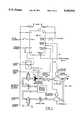
- FIG. 1is a schematic diagram of a typical fluid network employing the present monitoring system
- FIG. 2Ais a schematic diagram of pressure signal timing wave forms
- FIG. 2Bis a schematic diagram of time-dependent pressure signal
- FIG. 3is a schematic diagram illustrating transducer signal conditioning and alarm generation circuitry
- FIG. 4is a schematic LCM-20 System Block Diagram.
- the systemincorporates a captive column 10 of lubricant oil 11 which is pumped by a positive displacement injector 12. Air from line 13 is used to disburse the oil out of the nozzle of assembly 14. The air is low in velocity and employed for momentum transfer to the oil not as a shearing process. Two pressure transducers are employed for each lubrication point--an AIR PRESSURE TRANSDUCER for air line 13 and an OIL PRESSURE TRANSDUCER for captive column 10 of lubricant oil.
- Transducer output signalsare respectively fed by line 15, carrying a voltage proportional to air pressure in line 13 and by line 16, carrying a voltage proportional to oil pressure in captive column 10, into a control module 17 designated "LCM-20", where the signals are processed as hereinafter described.
- the OIL PRESSURE TRANSDUCERis incorporated in the fluid network between the two check valves designated as INTEGRAL CHECK VALVE (Pc1), and INTEGRAL CHECK VALVE (Pc2), and thus measures the captive oil pressure in column 10.
- Pressure spike detectionis derived from the oil pressure signal in order to verify actual delivery of lubricant.
- the injector firingis controlled directly by CYCLE TIMER circuitry within the control module LCM-20 as indicated in FIG. 4.
- the injectoris a positive displacement pump air actuated with a typical INJECTOR AIR REGULATOR pressure of 50 PSI, and a 20:1 piston/piston head ratio producing a maximum achievable pressure head, with a dead-ended gauge, of 1000 PSI.
- nozzle cavity 14which opens almost instantaneously after the introduction of fluid into captive column 10.
- the rate at which the injector is cycled by clock signal within the CYCLE TIMER control modulethus determines the total volume of oil delivered to the nozzle cavity per unit time and subsequently the rate of lubricant delivered to the process part.
- the captive oil columndevelops a characteristic pressure which is comprised of a static (or steady-state) component, Pss, and a transient component, Pt, which is superimposed on the pressure waveform during the injector pulse.
- Pssa static (or steady-state) component
- Pta transient component
- the right side of FIG. 2illustrates waveforms having a higher transient spike, Pt1, and higher steady-state, Pss1 incident to higher injection frequency than Pt2 and Pss2 for lower time frequency.
- a similar higher transient spike and steady-statewill result from an adjustable higher volume stroke of the injector piston so that the resultant pressure waveform reflects the combination of stroke and frequency.
- Pressure variations in the oil column 10are further complicated by the effects of cavitation, compressibility of the process fluid, and the nozzle back pressure induced by the air during oil flow. Variation in steady-state pressure is overcome by utilizing the spike-detect feature of the present system which enables a 100% positive detection of fluid delivery to the nozzle.
- Utilization of pressure transducers, along with LCM-20 monitoringallows the end user to detect blockages in the system (through high pressure detect) leaks, or breakage of fluid lines (through low pressure detect) and transient flow to the nozzle (through the spike detect feature).
- High and low pressure detectionis limited in the CYCLE TIMER to that portion of the CYCLE TIME, t cyc, between DWELL TIME to FIRE INJECTOR, t dwell, while the spike detect feature is limited to each t dwell period. This provides for a much more reliable and fault-free lubrication process than has been possible with other systems.
- Pressure transducers(of the F.W. Bridge configuration utilizing either silicon micro-electronic sensors or piezo electric crystals) are employed to measure the pressure of the air and oil lines.
- Commercially available Series 300, Transamerica - Delaval, Barksdale Div. pressure transducershave been employed and are satisfactory for the purpose.
- Electric signalswhich are sent to the control module, LCM-20, are processed to generate "fault" conditions based upon these signals.
- FIG. 3illustrating schematically the processing circuits to accommodate the transducers
- electronic differentiating of the signal condition transducer outputis accomplished by imposition upon a HIGH PASS FILTER, rendering it independent of any base line or steady state component.
- the resultant signalis fed into a comparator circuit used to discriminate rates of pressure increase or decrease against a preset reference level.
- a commercial comparator which has been employed in such circuitis produced by National Semiconductor Corporation under the designation LM339 which is combined with Texas Instruments dual D-type positive edge triggered transparent latch "flip-flops" designated 74LS74 which signal high and low alarms detected by the comparators.
- the OIL PRESSURE TRANSDUCERproduces a voltage ⁇ V directly proportional to pressure ⁇ P in oil column 10 which is amplified by TRANSDUCER DIFFERENTIAL AMPLIFIER to provide, for example, 15 for 300 PSI.
- the TTL HIGH P ALARM, TTL 74LS74is employed with comparator LM339 to monitor a high set point, such as 10 V/200 PSI, while the corresponding TTL LOW P ALARM monitors a low set point, such as 5 V/100 PSI, each limited to the steady-state time between injections.
- Such high and low alarmswill indicate respectively, faults such as downstream blockage interfering with nozzle delivery from captive column 10, but will not detect loss of the injector signal or a malfunction of subsequent fluid delivery.
- THE HIGH PASS FILTER circuittimed to operate only during the pressure spike DWELL TIME TO FIRE INJECTOR, t dwell, detects rate of change of pressure, independent of steady-state base line pressure, rather than a high or low fixed set point, and therefore can verify effective injector pumping and fluid delivery adjustments.
- rate of change of pressureindependent of steady-state base line pressure, rather than a high or low fixed set point, and therefore can verify effective injector pumping and fluid delivery adjustments.
- the systememploys the technique of time-differentiating the output of a single nondifferential pressure transducer to detect transient pressure changes in an injector-pumped captive column of oil, thereby discerning the transient or time dependent flow rate.
- the excitation circuitswithin the LCM-20, are the excitation circuits, signal conditioning circuits, and comparator-logic/signal conditioning circuits to accommodate these transducers.
- the reference level settingswhich determine lubrication system fault conditions, as well as an analog-to-digital conversion circuit which can display the reference levels and actual pressure readings.
- Such LCM-20 Injection Lubrication Control Systemin a typical installation comprise primary subsystems as schematically illustrated in the block diagram of FIG. 4. These include:
- This subsystemdecodes and multiplexes the digital alarm signals from the various systems in the LCM-20 and communicates these signals with the Display Drivers, AC logic Outputs, TTL Interface Port and Expansion Port. It also comprises the LED Alarm Indicator Lamps and driver circuitry.
- the Expansion Portaccommodates 15 volt and TTL level (5 volt) digital signals which communicate status information between the Main Unit and the LCM-20E Expansion Units. In addition, the Cycle Timer signal and multiplexed analog signals (from the Expansion Units) are available at this interface.
- the TTL Interfaceis used to receive a polled address from an external controller module and read out the multiplexed alarm status signal.
- This circuitryhandles communication with a 110 VAC Ladder Logic which is usually employed in standard process control, robotic or factory automation applications. Control switches and relay contacts can be used to generate alarm signals which are subsequently multiplexed into the system alarm logic.
- These inputscomprise opto-isolator circuits with high noise immunity to industrial environments where motors, power lines, arcing equipment, lightning and other sources of interference can distort the internal low-level signals of a process controller.
- the outputsalso incorporate optically-isolated SSRS (solid-state relays) and are used to generate 110 VAC alarm signals based upon the system status.
- the LCM-20accommodates transducers of the balanced impedance 4-wire configuration (Wheatstone-bridge). These include most types of pressure and torque transducers, load cells, strain gauges, accelorometers, Hall effect sensors and 4-wire temperature sensors.
- sensors of the 2-wire configuration, RTDs, thermocouples, thermistors (NPTs and RPTs), photoemissive, photoconductive and semiconductor diode and transistor sensorscan be utilized by the appropriate calibration and wiring of the device.
- the unitprovides a precision 10.00 volt excitation (this can be changed internally, for example to 5 volt excitation depending upon the type of transducer).
- the input amplifierscomprise a high input-impedance instrumentation amplifier configuration with high common-mode rejection ratio and tunable gain and offset adjustments.
- the output signalsare fed into the Reference Comparators whose reference values are preset by the multi-turn Alarm Set Point Potentiometers. These signals represent the High, Low and Spike Alarm conditions associated with each Transducer.
- the resultant digital signalis then latched time-correlated with the Cycle Timer/Injector Signal, and sent to the Alarm Decoding Logic.
- This circuitryis responsible for routing of the analog signals from the Transducer Signal Conditioning Circuits to the A/D (Analog-to-Digital) Converter and producing the digit-multiplexed BCD signals which are sent to the LCD display.
- These analog signalsinclude the "real-time" Transducer readings, the analog reference levels (Alarm Set-Points) and the corresponding analog signals from the Expansion Units.
- the A/D Converteruses the Dual-Slope Integrating convention and refreshes about 3 times a second. With the Dual-Slope Integrator, the input voltage is time-integrated (in time T1) and compared against a time-integrated reference, Vref (in time T2).
- the resultis recalibrated to read out in units of the process variable (for example PSI) on the LCD display by the display driver circuitry.
- the parameter selectionis determined by the action of the Function Select and XDCR Select Binary Switches upon the analog multiplexer circuit.
- the Cycle Timergenerates a 10 Hz to 0.001 Hz output which is set via the Cycle Time Set Switches.
- a 110 VAC output control signal(to fire the Injector or other electric, pneumatic, hydraulic control components) is provided through an optically isolated SSR as shown. This signal is also used to time-correlate the transparent latches associated with the Transducer generated alarm signals.
- Dwell Timeis internally settable from 0.1 sec. to 1.6 sec.
- the Enable inputstarts and stops the Cycle Timer and resets the timing cycle upon activation by a 110 VAC control signal.
- the LCM-20has a "first-fire" option which resets the cycle timer in the event that it is disabled and subsequently re-enabled. Timing can be displayed on the integral LCD display via the FUNCTION Select switch.
- the present inventionis primarily directed to the development of a dependable "fault" signal per se which verifies normal pressure variations, such as incident to injection frequency and stroke adjustments, while detecting abnormal pressure irregularities with a discriminating signal which may be used to produce any desired control function.
Landscapes
- Engineering & Computer Science (AREA)
- General Engineering & Computer Science (AREA)
- Mechanical Engineering (AREA)
- Examining Or Testing Airtightness (AREA)
- Fluid-Pressure Circuits (AREA)
- Testing Of Devices, Machine Parts, Or Other Structures Thereof (AREA)
Abstract
Description
Claims (11)
Priority Applications (4)
| Application Number | Priority Date | Filing Date | Title |
|---|---|---|---|
| US07/411,678US5038893A (en) | 1989-09-25 | 1989-09-25 | Lubrication monitoring system |
| DE69017993TDE69017993T2 (en) | 1989-09-25 | 1990-08-20 | Monitoring system for lubrication. |
| EP90115882AEP0419835B1 (en) | 1989-09-25 | 1990-08-20 | Lubrication monitoring system |
| JP2250436AJPH03125098A (en) | 1989-09-25 | 1990-09-21 | Lubrication monitoring system |
Applications Claiming Priority (1)
| Application Number | Priority Date | Filing Date | Title |
|---|---|---|---|
| US07/411,678US5038893A (en) | 1989-09-25 | 1989-09-25 | Lubrication monitoring system |
Publications (1)
| Publication Number | Publication Date |
|---|---|
| US5038893Atrue US5038893A (en) | 1991-08-13 |
Family
ID=23629878
Family Applications (1)
| Application Number | Title | Priority Date | Filing Date |
|---|---|---|---|
| US07/411,678Expired - LifetimeUS5038893A (en) | 1989-09-25 | 1989-09-25 | Lubrication monitoring system |
Country Status (4)
| Country | Link |
|---|---|
| US (1) | US5038893A (en) |
| EP (1) | EP0419835B1 (en) |
| JP (1) | JPH03125098A (en) |
| DE (1) | DE69017993T2 (en) |
Cited By (45)
| Publication number | Priority date | Publication date | Assignee | Title |
|---|---|---|---|---|
| US5310020A (en)* | 1993-06-09 | 1994-05-10 | Ingersoll-Rand Company | Self contained lubricating oil system for a centrifugal compressor |
| US5485491A (en)* | 1994-03-31 | 1996-01-16 | Westinghouse Electric Corporation | Online diagnostic system for rotating electrical apparatus |
| US5495917A (en)* | 1995-01-03 | 1996-03-05 | Pax Products, Inc. | Liquid distributing apparatus for lubricating parts |
| US5788012A (en)* | 1996-05-06 | 1998-08-04 | Korea Lube-Tech Co., Ltd. | Method and apparatus for automatically feeding lubricating oil using microcomputer |
| US5796262A (en)* | 1996-02-14 | 1998-08-18 | Westinghouse Electric Corporation | Method and apparatus for diagnosing bearing insulation impedance of a rotating electrical apparatus |
| US6023961A (en)* | 1998-04-02 | 2000-02-15 | Reliance Electric Industrial Company | Micro-viscosity sensor and lubrication analysis system employing the same |
| US6053285A (en)* | 1998-01-14 | 2000-04-25 | G.P. Reeves, Inc. | Apparatus for dispensing measured quantities of lubricant |
| US6161515A (en)* | 1998-07-29 | 2000-12-19 | Borgwarner Inc. | Method for controlling output pressure of an engine oil pump |
| US6167318A (en)* | 1997-12-22 | 2000-12-26 | Alemite Corporation | Oil mist generating system and method |
| US6196057B1 (en) | 1998-04-02 | 2001-03-06 | Reliance Electric Technologies, Llc | Integrated multi-element lubrication sensor and lubricant health assessment |
| US6212958B1 (en) | 1998-07-16 | 2001-04-10 | Lincoln Industrial Corporation | Flow sensing assembly and method |
| US6286627B1 (en) | 1999-08-25 | 2001-09-11 | Lincoln Industrial Corporation | Fluid dispensing apparatus |
| US6324899B1 (en) | 1998-04-02 | 2001-12-04 | Reliance Electric Technologies, Llc | Bearing-sensor integration for a lubrication analysis system |
| US20020112759A1 (en)* | 2001-02-17 | 2002-08-22 | Lindauer Dornier Gesellschaft Mbh | Apparatus for dosing lubricant into an air line |
| US20030000773A1 (en)* | 2000-01-21 | 2003-01-02 | Wolfgang Engler | Additive nebulising device |
| DE4344788C2 (en)* | 1992-12-28 | 2003-02-20 | Nsk Ltd | lubricator |
| US6545610B2 (en)* | 1999-05-25 | 2003-04-08 | Kulite Semiconductor Products, Inc. | Pressure transducer and switch combination |
| US6546785B1 (en) | 1998-04-02 | 2003-04-15 | Rockwell Automation Technologies, Inc. | System and method for dynamic lubrication adjustment for a lubrication analysis system |
| US6622824B2 (en)* | 2001-03-07 | 2003-09-23 | Daniel H. Roehrborn | Lubrication supply system for a machine |
| US20040065511A1 (en)* | 2000-11-15 | 2004-04-08 | Christian Javelly | System for lubricating and monitoring a lubricatable element |
| US20050025631A1 (en)* | 2003-07-30 | 2005-02-03 | Equistar Chemicals L.P. | System and method for monitoring the mechanical condition of a reciprocating compressor |
| US20050087560A1 (en)* | 2003-09-11 | 2005-04-28 | Markus Urban | Lubricating tool for feeding a lubricating mixture to a cutter |
| US7134323B1 (en) | 1998-04-02 | 2006-11-14 | Rockwell Automation Technologies, Inc. | System and method for dynamic lubrication adjustment for a lubrication analysis system |
| US20080046196A1 (en)* | 2006-08-15 | 2008-02-21 | General Electric Company | System and method for monitoring a reciprocating compressor |
| US20080054727A1 (en)* | 2006-08-30 | 2008-03-06 | Landmann Wolf S | Solid state pressure switch |
| US20090100913A1 (en)* | 2006-04-28 | 2009-04-23 | Diesel United Ltd | Conductive material concentration measuring device and magnetic material concentration measuring device |
| US7581434B1 (en) | 2003-09-25 | 2009-09-01 | Rockwell Automation Technologies, Inc. | Intelligent fluid sensor for machinery diagnostics, prognostics, and control |
| US20100243070A1 (en)* | 2007-10-17 | 2010-09-30 | Atlas Copco Rock Drills Ab | Device and method for controlling supply of lubricant at a work vehicle |
| US20110296902A1 (en)* | 2009-03-05 | 2011-12-08 | Egon Eisenbacher | Method for metered dispensing of lubricant |
| US20110303491A1 (en)* | 2010-06-11 | 2011-12-15 | Jenkins Maurice A | Backup Lubrication System For A Rotor Bearing |
| WO2012074626A1 (en)* | 2010-11-29 | 2012-06-07 | Lincoln Industrial Corporation | Pump system |
| US20130008745A1 (en)* | 2011-07-05 | 2013-01-10 | Honeywell International Inc. | Lubrication systems with nozzle blockage detection systems |
| US20130277148A1 (en)* | 2012-04-20 | 2013-10-24 | Aktiebolaget Skf | Lubrication system and controller |
| TWI461624B (en)* | 2011-11-04 | 2014-11-21 | ||
| CN104732052A (en)* | 2013-12-23 | 2015-06-24 | 上银科技股份有限公司 | Method for judging oil injection time of linear transmission element |
| US9086186B2 (en) | 2011-10-14 | 2015-07-21 | Lincoln Industrial Corporation | System having removable lubricant reservoir and lubricant refilling station |
| US9222618B2 (en) | 2010-11-29 | 2015-12-29 | Lincoln Industrial Corporation | Stepper motor driving a lubrication pump providing uninterrupted lubricant flow |
| US9388940B2 (en) | 2010-11-29 | 2016-07-12 | Lincoln Industrial Corporation | Variable speed stepper motor driving a lubrication pump system |
| US9429452B2 (en) | 2012-02-15 | 2016-08-30 | Wave Control Systems Ltd. | Method and apparatus for continuous online monitoring of a pulsating pump |
| US20170015426A1 (en)* | 2015-07-13 | 2017-01-19 | Hamilton Sundstrand Corporation | Raf bit for surge detection |
| US9671065B2 (en) | 2013-10-17 | 2017-06-06 | Lincoln Industrial Corporation | Pump having wear and wear rate detection |
| CN114054542A (en)* | 2021-11-08 | 2022-02-18 | 泰尔重工股份有限公司 | Intelligent monitoring and analyzing system and algorithm for hot-rolling drum lubricating oil circuit |
| US20220282832A1 (en)* | 2021-03-07 | 2022-09-08 | Guo-Wei Wang | Lubrication system |
| EP4299968A1 (en)* | 2022-07-01 | 2024-01-03 | Durable Devices AB | Monitoring the operation of a lubrication apparatus |
| US20240288117A1 (en)* | 2021-06-21 | 2024-08-29 | Safran Aircraft Engines | Device for detecting leaks in an aircraft engine lubricating oil circuit |
Families Citing this family (5)
| Publication number | Priority date | Publication date | Assignee | Title |
|---|---|---|---|---|
| US5332064A (en)* | 1993-06-03 | 1994-07-26 | Liu Jung Hsun | Control apparatus for lubrication pump |
| DE19857289C1 (en)* | 1998-12-13 | 2000-05-04 | Brueckner Maschbau | Method of lubricating a transport system or parts of it such as guide ways or rails and corresponding lubricating appliances |
| EP2226547B1 (en)* | 2009-03-04 | 2013-01-09 | Delimon GmbH | Lubricant spraying device |
| CN103422933A (en)* | 2012-05-14 | 2013-12-04 | 瓦锡兰瑞士公司 | Method for lubricating a piston-in-cylinder arrangement of a reciprocating piston combustion engine and cylinder lubricating arrangement |
| TWI564500B (en)* | 2015-05-22 | 2017-01-01 | 普陽商貿有限公司 | Intelligent oil-gas mixing lubrication system |
Citations (14)
| Publication number | Priority date | Publication date | Assignee | Title |
|---|---|---|---|---|
| US3007414A (en)* | 1956-11-07 | 1961-11-07 | Long | Control system for pressurized conduits |
| US4072934A (en)* | 1977-01-19 | 1978-02-07 | Wylain, Inc. | Method and apparatus for detecting a blockage in a vapor flow line |
| US4292841A (en)* | 1979-07-11 | 1981-10-06 | Creative Tool Company | Compression rate analyzer |
| US4444292A (en)* | 1981-08-12 | 1984-04-24 | Standard Oil Company (Indiana) | Method and apparatus for lubricating a machine |
| US4448063A (en)* | 1983-02-03 | 1984-05-15 | Ingersoll-Rand Company | Engine cold testing |
| US4613059A (en)* | 1985-05-15 | 1986-09-23 | Nordson Corporation | Pressure pulse masking circuit for a pressure monitor in a dispensing system |
| US4668948A (en)* | 1983-03-10 | 1987-05-26 | Nordson Corporation | Dispenser malfunction detector |
| US4712736A (en)* | 1981-03-27 | 1987-12-15 | Gaydon Technology Limited | Method and system for maintaining a spray pattern |
| US4735286A (en)* | 1985-04-19 | 1988-04-05 | Koyo Seiko Co., Ltd. | Detector for detecting malfunction of lubricating oil feeder |
| US4800367A (en)* | 1985-12-13 | 1989-01-24 | Alfa-Laval Separation Ab | Method of sensing and indicating errors in a dosing circuit |
| US4840148A (en)* | 1987-09-10 | 1989-06-20 | Brunswick Corporation | Two cycle engine with low pressure crankcase fuel injection |
| US4846831A (en)* | 1988-04-27 | 1989-07-11 | Skillin David E | Manual back-up drive for artificial heart |
| US4858645A (en)* | 1988-10-24 | 1989-08-22 | G. P. Reeves In. | Lubricant delivery system including flow measuring |
| US4862393A (en)* | 1988-01-12 | 1989-08-29 | Cummins Engine Company, Inc. | Oil change interval monitor |
Family Cites Families (5)
| Publication number | Priority date | Publication date | Assignee | Title |
|---|---|---|---|---|
| GB2046371A (en)* | 1979-01-30 | 1980-11-12 | Cincinnati Milacron Inc | Lubricating system |
| DE3244738A1 (en)* | 1982-12-03 | 1984-06-07 | Uraca Pumpenfabrik GmbH & Co KG, 7432 Urach | Device for monitoring valves in an intermittently operating machine |
| US4785913A (en)* | 1986-11-19 | 1988-11-22 | Orsco Incorporated | Spindle lubricating system |
| US4823552A (en)* | 1987-04-29 | 1989-04-25 | Vickers, Incorporated | Failsafe electrohydraulic control system for variable displacement pump |
| US4886422A (en)* | 1987-07-09 | 1989-12-12 | Tokyo Keiki Company Ltd. | Control apparatus of variable delivery pump |
- 1989
- 1989-09-25USUS07/411,678patent/US5038893A/ennot_activeExpired - Lifetime
- 1990
- 1990-08-20EPEP90115882Apatent/EP0419835B1/ennot_activeExpired - Lifetime
- 1990-08-20DEDE69017993Tpatent/DE69017993T2/ennot_activeExpired - Fee Related
- 1990-09-21JPJP2250436Apatent/JPH03125098A/enactivePending
Patent Citations (14)
| Publication number | Priority date | Publication date | Assignee | Title |
|---|---|---|---|---|
| US3007414A (en)* | 1956-11-07 | 1961-11-07 | Long | Control system for pressurized conduits |
| US4072934A (en)* | 1977-01-19 | 1978-02-07 | Wylain, Inc. | Method and apparatus for detecting a blockage in a vapor flow line |
| US4292841A (en)* | 1979-07-11 | 1981-10-06 | Creative Tool Company | Compression rate analyzer |
| US4712736A (en)* | 1981-03-27 | 1987-12-15 | Gaydon Technology Limited | Method and system for maintaining a spray pattern |
| US4444292A (en)* | 1981-08-12 | 1984-04-24 | Standard Oil Company (Indiana) | Method and apparatus for lubricating a machine |
| US4448063A (en)* | 1983-02-03 | 1984-05-15 | Ingersoll-Rand Company | Engine cold testing |
| US4668948A (en)* | 1983-03-10 | 1987-05-26 | Nordson Corporation | Dispenser malfunction detector |
| US4735286A (en)* | 1985-04-19 | 1988-04-05 | Koyo Seiko Co., Ltd. | Detector for detecting malfunction of lubricating oil feeder |
| US4613059A (en)* | 1985-05-15 | 1986-09-23 | Nordson Corporation | Pressure pulse masking circuit for a pressure monitor in a dispensing system |
| US4800367A (en)* | 1985-12-13 | 1989-01-24 | Alfa-Laval Separation Ab | Method of sensing and indicating errors in a dosing circuit |
| US4840148A (en)* | 1987-09-10 | 1989-06-20 | Brunswick Corporation | Two cycle engine with low pressure crankcase fuel injection |
| US4862393A (en)* | 1988-01-12 | 1989-08-29 | Cummins Engine Company, Inc. | Oil change interval monitor |
| US4846831A (en)* | 1988-04-27 | 1989-07-11 | Skillin David E | Manual back-up drive for artificial heart |
| US4858645A (en)* | 1988-10-24 | 1989-08-22 | G. P. Reeves In. | Lubricant delivery system including flow measuring |
Cited By (79)
| Publication number | Priority date | Publication date | Assignee | Title |
|---|---|---|---|---|
| DE4344788C2 (en)* | 1992-12-28 | 2003-02-20 | Nsk Ltd | lubricator |
| US5310020A (en)* | 1993-06-09 | 1994-05-10 | Ingersoll-Rand Company | Self contained lubricating oil system for a centrifugal compressor |
| US5485491A (en)* | 1994-03-31 | 1996-01-16 | Westinghouse Electric Corporation | Online diagnostic system for rotating electrical apparatus |
| US5495917A (en)* | 1995-01-03 | 1996-03-05 | Pax Products, Inc. | Liquid distributing apparatus for lubricating parts |
| US5796262A (en)* | 1996-02-14 | 1998-08-18 | Westinghouse Electric Corporation | Method and apparatus for diagnosing bearing insulation impedance of a rotating electrical apparatus |
| US5788012A (en)* | 1996-05-06 | 1998-08-04 | Korea Lube-Tech Co., Ltd. | Method and apparatus for automatically feeding lubricating oil using microcomputer |
| US6167318A (en)* | 1997-12-22 | 2000-12-26 | Alemite Corporation | Oil mist generating system and method |
| US6053285A (en)* | 1998-01-14 | 2000-04-25 | G.P. Reeves, Inc. | Apparatus for dispensing measured quantities of lubricant |
| US6546785B1 (en) | 1998-04-02 | 2003-04-15 | Rockwell Automation Technologies, Inc. | System and method for dynamic lubrication adjustment for a lubrication analysis system |
| US6877360B1 (en)* | 1998-04-02 | 2005-04-12 | Rockwell Automation Technologies, Inc. | System and method for dynamic lubrication adjustment for a lubrication analysis system |
| US6023961A (en)* | 1998-04-02 | 2000-02-15 | Reliance Electric Industrial Company | Micro-viscosity sensor and lubrication analysis system employing the same |
| US6324899B1 (en) | 1998-04-02 | 2001-12-04 | Reliance Electric Technologies, Llc | Bearing-sensor integration for a lubrication analysis system |
| US7690246B1 (en) | 1998-04-02 | 2010-04-06 | Rockwell Automation Technologies, Inc. | System and method for dynamic lubrication adjustment for a lubrication analysis system |
| US7493799B1 (en) | 1998-04-02 | 2009-02-24 | Rockwell Automation Technologies, Inc. | System and method for dynamic lubrication adjustment for a lubrication analysis system |
| US7134323B1 (en) | 1998-04-02 | 2006-11-14 | Rockwell Automation Technologies, Inc. | System and method for dynamic lubrication adjustment for a lubrication analysis system |
| US6196057B1 (en) | 1998-04-02 | 2001-03-06 | Reliance Electric Technologies, Llc | Integrated multi-element lubrication sensor and lubricant health assessment |
| US6212958B1 (en) | 1998-07-16 | 2001-04-10 | Lincoln Industrial Corporation | Flow sensing assembly and method |
| US6161515A (en)* | 1998-07-29 | 2000-12-19 | Borgwarner Inc. | Method for controlling output pressure of an engine oil pump |
| US6545610B2 (en)* | 1999-05-25 | 2003-04-08 | Kulite Semiconductor Products, Inc. | Pressure transducer and switch combination |
| US6405810B1 (en) | 1999-08-25 | 2002-06-18 | Lincoln Industrial Corporation | Method of lubricating and lubricant spraying apparatus |
| US6286627B1 (en) | 1999-08-25 | 2001-09-11 | Lincoln Industrial Corporation | Fluid dispensing apparatus |
| US20030000773A1 (en)* | 2000-01-21 | 2003-01-02 | Wolfgang Engler | Additive nebulising device |
| US7665577B2 (en)* | 2000-11-15 | 2010-02-23 | Willy Vogel Ag | System for lubricating and monitoring a lubricatable element |
| US20040065511A1 (en)* | 2000-11-15 | 2004-04-08 | Christian Javelly | System for lubricating and monitoring a lubricatable element |
| US6832620B2 (en)* | 2001-02-17 | 2004-12-21 | Lindauer Dornier Gesellschaft Mbh | Apparatus for dosing lubricant into an air line |
| US20020112759A1 (en)* | 2001-02-17 | 2002-08-22 | Lindauer Dornier Gesellschaft Mbh | Apparatus for dosing lubricant into an air line |
| US6622824B2 (en)* | 2001-03-07 | 2003-09-23 | Daniel H. Roehrborn | Lubrication supply system for a machine |
| US7056097B2 (en)* | 2003-07-30 | 2006-06-06 | Equistar Chemicals L.P. | System and method for monitoring the mechanical condition of a reciprocating compressor |
| US20050025631A1 (en)* | 2003-07-30 | 2005-02-03 | Equistar Chemicals L.P. | System and method for monitoring the mechanical condition of a reciprocating compressor |
| US20050087560A1 (en)* | 2003-09-11 | 2005-04-28 | Markus Urban | Lubricating tool for feeding a lubricating mixture to a cutter |
| US7493988B2 (en) | 2003-09-11 | 2009-02-24 | Airbus Deutschland Gmbh | Lubricating tool for feeding a lubricating mixture to a cutter |
| US7581434B1 (en) | 2003-09-25 | 2009-09-01 | Rockwell Automation Technologies, Inc. | Intelligent fluid sensor for machinery diagnostics, prognostics, and control |
| US20090100913A1 (en)* | 2006-04-28 | 2009-04-23 | Diesel United Ltd | Conductive material concentration measuring device and magnetic material concentration measuring device |
| US8037740B2 (en)* | 2006-04-28 | 2011-10-18 | Diesel United, Ltd. | Conductive material concentration measuring device and magnetic material concentration measuring device |
| US8348628B2 (en) | 2006-08-15 | 2013-01-08 | General Electric Company | System and method for monitoring a reciprocating compressor |
| JP2008045547A (en)* | 2006-08-15 | 2008-02-28 | General Electric Co <Ge> | System and method for monitoring reciprocating compressor |
| US20080046196A1 (en)* | 2006-08-15 | 2008-02-21 | General Electric Company | System and method for monitoring a reciprocating compressor |
| US7595570B2 (en) | 2006-08-30 | 2009-09-29 | Kulite Semiconductor Products, Inc. | Solid state pressure switch |
| US20080054727A1 (en)* | 2006-08-30 | 2008-03-06 | Landmann Wolf S | Solid state pressure switch |
| US20100243070A1 (en)* | 2007-10-17 | 2010-09-30 | Atlas Copco Rock Drills Ab | Device and method for controlling supply of lubricant at a work vehicle |
| US8464837B2 (en)* | 2007-10-17 | 2013-06-18 | Atlas Copco Rock Drills Ab | Device and method for controlling supply of lubricant at a work vehicle |
| US8978828B2 (en)* | 2009-03-05 | 2015-03-17 | Perma-Tec Gmbh & Co. Kg | Method for metered dispensing of lubricant |
| US20110296902A1 (en)* | 2009-03-05 | 2011-12-08 | Egon Eisenbacher | Method for metered dispensing of lubricant |
| US20110303491A1 (en)* | 2010-06-11 | 2011-12-15 | Jenkins Maurice A | Backup Lubrication System For A Rotor Bearing |
| US9151327B2 (en)* | 2010-06-11 | 2015-10-06 | Siemens Aktiengesellschaft | Backup lubrication system for a rotor bearing |
| CN103429946A (en)* | 2010-11-29 | 2013-12-04 | 林肯工业公司 | Pump system |
| US8936135B2 (en) | 2010-11-29 | 2015-01-20 | Lincoln Industrial Corporation | Pump having heated reservoir |
| WO2012074626A1 (en)* | 2010-11-29 | 2012-06-07 | Lincoln Industrial Corporation | Pump system |
| TWI447325B (en)* | 2010-11-29 | 2014-08-01 | Lincoln Ind Corp | Pump having diagnostic system |
| US8844679B2 (en) | 2010-11-29 | 2014-09-30 | Lincoln Industrial Corporation | Pump having venting and non-venting piston return |
| TWI454629B (en)* | 2010-11-29 | 2014-10-01 | Lincoln Ind Corp | Pump having venting and non-venting piston return |
| US9222618B2 (en) | 2010-11-29 | 2015-12-29 | Lincoln Industrial Corporation | Stepper motor driving a lubrication pump providing uninterrupted lubricant flow |
| TWI463091B (en)* | 2010-11-29 | 2014-12-01 | Lincoln Ind Corp | Pump having heated reservoir |
| TWI463092B (en)* | 2010-11-29 | 2014-12-01 | Lincoln Ind Corp | Pump having stirrer and direct feed |
| US9388940B2 (en) | 2010-11-29 | 2016-07-12 | Lincoln Industrial Corporation | Variable speed stepper motor driving a lubrication pump system |
| TWI471499B (en)* | 2010-11-29 | 2015-02-01 | Lincoln Ind Corp | Pump having stepper motor and overdrive control |
| US10851940B2 (en) | 2010-11-29 | 2020-12-01 | Lincoln Industrial Corporation | Pump having diagnostic system |
| US9022177B2 (en) | 2010-11-29 | 2015-05-05 | Lincoln Industrial Corporation | Pump having stepper motor and overdrive control |
| US12025269B2 (en) | 2010-11-29 | 2024-07-02 | Lincoln Industrial Corporation | Pump having diagnostic system |
| US9212779B2 (en) | 2010-11-29 | 2015-12-15 | Lincoln Industrial Corporation | Pump having diagnostic system |
| US9140407B2 (en) | 2010-11-29 | 2015-09-22 | Lincoln Industrial Corporation | Pump having stirrer and direct feed |
| US20130008745A1 (en)* | 2011-07-05 | 2013-01-10 | Honeywell International Inc. | Lubrication systems with nozzle blockage detection systems |
| US8596417B2 (en)* | 2011-07-05 | 2013-12-03 | Honeywell International Inc. | Lubrication systems with nozzle blockage detection systems |
| US9086186B2 (en) | 2011-10-14 | 2015-07-21 | Lincoln Industrial Corporation | System having removable lubricant reservoir and lubricant refilling station |
| TWI461624B (en)* | 2011-11-04 | 2014-11-21 | ||
| US9429452B2 (en) | 2012-02-15 | 2016-08-30 | Wave Control Systems Ltd. | Method and apparatus for continuous online monitoring of a pulsating pump |
| US20130277148A1 (en)* | 2012-04-20 | 2013-10-24 | Aktiebolaget Skf | Lubrication system and controller |
| US9920878B2 (en)* | 2012-04-20 | 2018-03-20 | Lincoln Industrial Corporation | Lubrication system and controller |
| US9671065B2 (en) | 2013-10-17 | 2017-06-06 | Lincoln Industrial Corporation | Pump having wear and wear rate detection |
| CN104732052B (en)* | 2013-12-23 | 2018-09-11 | 上银科技股份有限公司 | Method for judging oil injection time of linear transmission element |
| CN104732052A (en)* | 2013-12-23 | 2015-06-24 | 上银科技股份有限公司 | Method for judging oil injection time of linear transmission element |
| US9988153B2 (en)* | 2015-07-13 | 2018-06-05 | Hamilton Sundstrand Space Systems | RAF bit for surge detection |
| US20170015426A1 (en)* | 2015-07-13 | 2017-01-19 | Hamilton Sundstrand Corporation | Raf bit for surge detection |
| US20220282832A1 (en)* | 2021-03-07 | 2022-09-08 | Guo-Wei Wang | Lubrication system |
| US11619348B2 (en)* | 2021-03-07 | 2023-04-04 | Guo-Wei Wang | Lubrication system |
| US20240288117A1 (en)* | 2021-06-21 | 2024-08-29 | Safran Aircraft Engines | Device for detecting leaks in an aircraft engine lubricating oil circuit |
| US12228245B2 (en)* | 2021-06-21 | 2025-02-18 | Safran Aircraft Engines | Device for detecting leaks in an aircraft engine lubricating oil circuit |
| CN114054542A (en)* | 2021-11-08 | 2022-02-18 | 泰尔重工股份有限公司 | Intelligent monitoring and analyzing system and algorithm for hot-rolling drum lubricating oil circuit |
| EP4299968A1 (en)* | 2022-07-01 | 2024-01-03 | Durable Devices AB | Monitoring the operation of a lubrication apparatus |
Also Published As
| Publication number | Publication date |
|---|---|
| EP0419835B1 (en) | 1995-03-22 |
| DE69017993T2 (en) | 1995-07-20 |
| JPH03125098A (en) | 1991-05-28 |
| EP0419835A1 (en) | 1991-04-03 |
| DE69017993D1 (en) | 1995-04-27 |
Similar Documents
| Publication | Publication Date | Title |
|---|---|---|
| US5038893A (en) | Lubrication monitoring system | |
| US4096746A (en) | Flow controller-flow sensor assembly for gas chromatographs and the like | |
| US4778450A (en) | Fluid flow control system | |
| US3748656A (en) | Apparatus for monitoring pressure variations in a fluid pressure system | |
| EP0110325A1 (en) | Flow rate control system | |
| EP2062021A1 (en) | Method and apparatus for the diagnosis of losses of liquid in pressure measuring sensors filled with pressure-transmitting liquids | |
| US4318674A (en) | Automatic liquid level controller | |
| Lodge et al. | Positive hole pressures and negative exit pressures generated by molten polyethylene flowing through a slit die | |
| US3375845A (en) | Fluid flow device | |
| CN105387328A (en) | Lubricating point terminal detecting device and lubricating system with the same | |
| EP0670476B1 (en) | A fluid sensor | |
| US3782168A (en) | Method and apparatus for calibrating and testing pressure responsive apparatus | |
| US20030223882A1 (en) | Flow measurement and control system for positive displacement pumps | |
| US4389164A (en) | Automatic liquid level controller | |
| JPH02213729A (en) | Flow meter for constant flow pump | |
| Karim et al. | Compensated mass balance method for oil pipeline leakage detection using SCADA | |
| EP0412929A2 (en) | Fuel control utilizing a multifunction valve | |
| WO1998036339A1 (en) | A self-regulating computerized proportional control device for a water pump | |
| US5811674A (en) | Coolant safety system for welding apparatus | |
| JPH026296A (en) | Fluid flow self-adjusting system | |
| US3300769A (en) | Oil deficiency indicator | |
| US2446740A (en) | Apparatus for calibrating fluid pressure gauges | |
| US1641673A (en) | Means for measuring the viscosity of fluids | |
| GB1086628A (en) | Improvements in or relating to the measurement of mass flow rate of gases | |
| JP2693481B2 (en) | Lubricant deterioration detector |
Legal Events
| Date | Code | Title | Description |
|---|---|---|---|
| AS | Assignment | Owner name:ORSCO INCORPORATED,, MICHIGAN Free format text:ASSIGNMENT OF ASSIGNORS INTEREST.;ASSIGNORS:WILLNER, CLIFFORD S.;WILLNER, CHRISTOPHER A.;REEL/FRAME:005195/0454 Effective date:19891017 | |
| STCF | Information on status: patent grant | Free format text:PATENTED CASE | |
| FPAY | Fee payment | Year of fee payment:4 | |
| SULP | Surcharge for late payment | ||
| REMI | Maintenance fee reminder mailed | ||
| FPAY | Fee payment | Year of fee payment:8 | |
| SULP | Surcharge for late payment | ||
| AS | Assignment | Owner name:HELLER FINANCIAL, INC., AS AGENT, ILLINOIS Free format text:(ASSIGNMENT OF ASSIGNOR'S INTEREST) RE-RECORD TO CORRECT THE NUMBER OF MICROFILM PAGES FROM 32 TO 14 AT REEL 012520, FRAME 0001.;ASSIGNORS:LINCOLN INDUSTRIAL CORPORATION;ORSCO, INC.;LN ACQUISITION CORP.;REEL/FRAME:012631/0582 Effective date:20011221 Owner name:HELLER FINANCIAL, INC., AS AGENT, ILLINOIS Free format text:INVALID RECORDING;ASSIGNORS:LINCOLN INDUSTRIAL CORPORATION;ORSCO, INC.;LN ACQUISITION CORP.;REEL/FRAME:012520/0001 Effective date:20011221 | |
| FPAY | Fee payment | Year of fee payment:12 | |
| AS | Assignment | Owner name:GENERAL ELECTRIC CAPITAL CORPORATION, AS US AGENT, Free format text:SECURITY AGREEMENT;ASSIGNOR:ORSOC, INC.;REEL/FRAME:015953/0046 Effective date:20050408 | |
| AS | Assignment | Owner name:ORSCO, INC., MISSOURI Free format text:RELEASE BY SECURED PARTY;ASSIGNOR:GENERAL ELECTRIC CAPITAL CORPORATION;REEL/FRAME:019605/0235 Effective date:20070711 | |
| AS | Assignment | Owner name:JPMORGAN CHASE BANK, N.A., AS COLLATERAL AGENT, NE Free format text:SECURITY AGREEMENT;ASSIGNORS:LINCOLN INDUSTRIAL CORPORATION;ORSCO, INC.;ALEMITE, LLC;REEL/FRAME:019773/0907 Effective date:20070711 | |
| AS | Assignment | Owner name:CAPITALSOURCE FINANCE LLC, AS COLLATERAL AGENT, MA Free format text:SECURITY AGREEMENT;ASSIGNORS:LINCOLN INDUSTRIAL CORPORATION;ORSCO, INC.;ALEMITE, LLC;REEL/FRAME:019781/0232 Effective date:20070711 | |
| AS | Assignment | Owner name:LN ACQUISITION CORP.,NEW YORK Free format text:RELEASE BY SECURED PARTY;ASSIGNOR:HELLER FINANCIAL, INC.;REEL/FRAME:024523/0473 Effective date:20050408 Owner name:ORSCO, INC.,MISSOURI Free format text:RELEASE BY SECURED PARTY;ASSIGNOR:HELLER FINANCIAL, INC.;REEL/FRAME:024523/0473 Effective date:20050408 Owner name:LINCOLN INDUSTRIAL CORPORATION,MISSOURI Free format text:RELEASE BY SECURED PARTY;ASSIGNOR:HELLER FINANCIAL, INC.;REEL/FRAME:024523/0473 Effective date:20050408 |