US5038456A - Fire resistant tank construction method - Google Patents
Fire resistant tank construction methodDownload PDFInfo
- Publication number
- US5038456A US5038456AUS07/514,544US51454490AUS5038456AUS 5038456 AUS5038456 AUS 5038456AUS 51454490 AUS51454490 AUS 51454490AUS 5038456 AUS5038456 AUS 5038456A
- Authority
- US
- United States
- Prior art keywords
- tank
- wall means
- shell
- providing
- space
- Prior art date
- Legal status (The legal status is an assumption and is not a legal conclusion. Google has not performed a legal analysis and makes no representation as to the accuracy of the status listed.)
- Expired - Lifetime
Links
Images

Classifications
- B—PERFORMING OPERATIONS; TRANSPORTING
- B65—CONVEYING; PACKING; STORING; HANDLING THIN OR FILAMENTARY MATERIAL
- B65D—CONTAINERS FOR STORAGE OR TRANSPORT OF ARTICLES OR MATERIALS, e.g. BAGS, BARRELS, BOTTLES, BOXES, CANS, CARTONS, CRATES, DRUMS, JARS, TANKS, HOPPERS, FORWARDING CONTAINERS; ACCESSORIES, CLOSURES, OR FITTINGS THEREFOR; PACKAGING ELEMENTS; PACKAGES
- B65D90/00—Component parts, details or accessories for large containers
- B65D90/48—Arrangements of indicating or measuring devices
- B65D90/50—Arrangements of indicating or measuring devices of leakage-indicating devices
- B65D90/501—Arrangements of indicating or measuring devices of leakage-indicating devices comprising hollow spaces within walls
- Y—GENERAL TAGGING OF NEW TECHNOLOGICAL DEVELOPMENTS; GENERAL TAGGING OF CROSS-SECTIONAL TECHNOLOGIES SPANNING OVER SEVERAL SECTIONS OF THE IPC; TECHNICAL SUBJECTS COVERED BY FORMER USPC CROSS-REFERENCE ART COLLECTIONS [XRACs] AND DIGESTS
- Y10—TECHNICAL SUBJECTS COVERED BY FORMER USPC
- Y10S—TECHNICAL SUBJECTS COVERED BY FORMER USPC CROSS-REFERENCE ART COLLECTIONS [XRACs] AND DIGESTS
- Y10S220/00—Receptacles
- Y10S220/901—Liquified gas content, cryogenic
- Y—GENERAL TAGGING OF NEW TECHNOLOGICAL DEVELOPMENTS; GENERAL TAGGING OF CROSS-SECTIONAL TECHNOLOGIES SPANNING OVER SEVERAL SECTIONS OF THE IPC; TECHNICAL SUBJECTS COVERED BY FORMER USPC CROSS-REFERENCE ART COLLECTIONS [XRACs] AND DIGESTS
- Y10—TECHNICAL SUBJECTS COVERED BY FORMER USPC
- Y10T—TECHNICAL SUBJECTS COVERED BY FORMER US CLASSIFICATION
- Y10T29/00—Metal working
- Y10T29/49—Method of mechanical manufacture
- Y10T29/49826—Assembling or joining
- Y10T29/49888—Subsequently coating
- Y—GENERAL TAGGING OF NEW TECHNOLOGICAL DEVELOPMENTS; GENERAL TAGGING OF CROSS-SECTIONAL TECHNOLOGIES SPANNING OVER SEVERAL SECTIONS OF THE IPC; TECHNICAL SUBJECTS COVERED BY FORMER USPC CROSS-REFERENCE ART COLLECTIONS [XRACs] AND DIGESTS
- Y10—TECHNICAL SUBJECTS COVERED BY FORMER USPC
- Y10T—TECHNICAL SUBJECTS COVERED BY FORMER US CLASSIFICATION
- Y10T29/00—Metal working
- Y10T29/49—Method of mechanical manufacture
- Y10T29/4998—Combined manufacture including applying or shaping of fluent material
Definitions
- This inventionrelates generally to tanks for flammable and combustible liquids, and more particularly concerns methods and means for making such tanks fire resistant in above-ground installation environments.
- Tanks holding flammable or combustible liquidscan be dangerous if not "fireproofed", i.e., made “fire resistant".
- fireproofedi.e., made "fire resistant”.
- the tanksleak flammable liquid, a fire danger will exist. Fire can weaken the lightweight tank walls and lead to tank collapse and spillage of tank contents. Also, prior tanks were not, in general, bullet resistant.
- the method of the inventionconcerns forming of tank apparatus adapted for transportation for installation above-ground to receive and dispense a liquid hydrocarbon or hydrocarbons, and includes the following steps:
- the thermal barrier materialmay be filled into the second space, i.e., the space between the intermediate and outer walls of the assembly; and that barrier may be allowed to expand as a foam to enclose the tank interior at the top, bottom and sides thereof.
- the first space closer to the liquids containing tank interior,may be maintained free of the barrier material.
- Another objectis to fabricate the inner wall means to define an inner tank forming the tank interior, and fabricating the intermediate wall means to define an intermediate tank extending about the inner tank; and also to fabricate the outer wall means to define an outer tank extending about the intermediate tank.
- Yet another objectis to provide the thermal barrier to include:
- fire-resistant materialmay be applied to an outer tank of the assembly defined by the outer wall means, with the thermal barrier means filling the space between the outer tank and an intermediate tank formed by the intermediate wall means.
- the fire-resistant materialmay be allowed to harden in situ to form a shell or shells, as will be explained.
- access portingmay be provided at the top of the three wall tank assembly to enable access to the inner tank interior; the bottom wall of the inner tank may be supported by the bottom wall of the intermediate tank; and the latter may be supported by thermal barrier structure in the space between the bottom wall of the intermediate and the outer tanks.
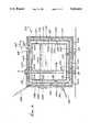
- FIG. 1is a perspective view of a metallic, three-wall tank assembly
- FIG. 2is a fragmentary section showing multiple sub-shells of fire-resistant material applied to the outer tank of FIG. 1;
- FIG. 3is a side elevation showing the fireproofed tank supported in a shallow receptacle at an installation site;
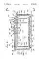
- FIG. 4is a view of modified triple-hulled tank apparatus
- FIG. 5is an end view of the FIG. 4 apparatus.
- FIG. 1shows a tank assembly 210 having lightweight wall means defining inner wall means 211, intermediate wall means 214 and outer wall means 216.
- the inner wall means 211typically forms an inner tank having a side wall or walls 211a, top wall 211b, and bottom wall 211c whereby an inner tank interior is formed at 212 for containing liquid hydrocarbon indicated at 213, or hydrocarbons, or the like.
- the intermediate wall meanstypically form an intermediate tank having a side wall or walls 214a, a top wall 214b, and bottom wall 214c whereby the intermediate tank encloses the inner tank, and a first space or spacing 215 is formed between the inner and intermediate tanks. See space 215a, 215b and 215c.
- the outer wall meanstypically forms an outer tank having side wall or walls 216a, top wall 216b and bottom wall 216c whereby the outer tank encloses the intermediate tank, and a second space or spacing 217 is formed between the outer and intermediate tanks. See space 217a, 217b and 217c.
- the three tanksmay be cylindrical, or may have multiple flat, parallel side walls. Side walls 211a, 214a and 216a may be parallel, as shown; top walls 211b, 214b and 216b may be parallel, as shown; and hollow walls 211c, 214c and 216c may be parallel, as indicated.
- Such wallsmay consist of steel and be less than one inch thick, for lightweight tank construction enhancing portability, for installation above ground at different sites, as desired. Glass fiber walls, or reinforced walls, resin impregnated, are also contemplated. Typically, steel walls are used and are about 10 gauge (1/8 to 1/4 inch thick).
- the tank lengthmay typically be about 5-20 feet.
- the wallsare typically interconnected by welds at their junctions, and internal braces may be provided.
- the overall tank wall thicknessis at least about two inches and is bullet (small caliber) resistant.
- the weight of the inner tank and its liquid contentsare transmitted to the intermediate tank, as via steel struts 219 in space 215c between bottom walls 211c and 214c.
- Such weight, together with the weight of the intermediate tankis transmitted to the bottom wall 216c of the outer tank, as via thermal barrier blocks 220 assembled or positioned in second space 217c, as shown, when the tanks are being assembled.
- Side spacer strutsmay be provided, locally, as at 208.
- the barrier indicated at 221a, 221b and 221cfills the bottom space 217c about the thermal barrier (insulative) blocks 270, all such barrier means then blocking inwardly directed heat transmission to the intermediate steel tank.
- the barrier materialcures in situ, after its injection and expansion.
- Usable thermal barrier materialsinclude polyurethane foam, VERMICULITE, and the like.
- the final thermal barrierconsists of the air and other gas in first space 215a, 215b and 215c, and prevents transmission to the contents of the inner tank of fire-generated heat which may for some reason have penetrated barrier foam 221a, 221b or 221c.
- FIG. 1also shows the provision of one or more pipe stubs 225 via which access may be gained to the tank assembly interior 212.
- the pipe 225is connected to top walls 211b, 214b and 216b to extend through them, and above wall 211b.
- the pipemay be downwardly extended at 225b into the inner tank interior for remaining liquid from that interior, as well as filling liquid into that interior.
- One or more access portsmay be provided to the spaces 215b, 217b, and to the interior space 212. Dipsticks may be inserted into the tank to measure the level of liquid hydrocarbon, i.e., flammable or combustible liquid (such as fuel) in the tank.
- Monitor meansmay be installed in the tank via one of the access ports to sense liquid level and transmit corresponding electrical signals to external apparatus that registers the liquid level for ready viewing.
- Fire-resistant materialis typically sprayed at 243, via a nozzle 242, onto the outermost tank walls 216a, 216b and 216c to form a first layer 250a which is allowed to harden or cure in situ. Then, if desired, a second nozzle, or the same nozzle, may be employed to spray the material onto layer 250a, forming a second layer 250b, also allowed to harden in situ.
- the combination of thus formed fire resistant sub-shellsform a composite shell, leak resistant, fire resistant, and projectile resistant, typically having a thickness between 1/4 inch and 1 inch, and which chars when heated to elevated temperatures (1,000° F. to 2,000° F.) as by intense flames.
- FIG. 2shows a wire mesh 267 applied between layers or shells 250a and 250b for strengthening purposes.
- the application of fire-resistant materialis preferably such as to coat the exposed pipe stub 225, and the supports 300 under the outer tank bottom wall 216c, as shown.
- An additional sub-shell of fire-resistant materialmay be used, as at 250c.
- the material 243 being sprayed onmay cling to the upright metal walls without sagging out of position, and also to have optimum fireproofing effect, it typically has an epoxide resin base, and chars when exposed to flame.
- CHARTEKsprayable two component intumescent epoxy fireproofing system
- the primer coatmay, for example, consist of polyamide epoxy resin, such as AMERON 71, SUBOX A8051, or VAL-CHEM 13-R-56, or ethyl silicate inorganic zinc (such as DIMETCOTE 6).
- the tank assemblyis supported by tank supports 300 beneath bottom wall 216a and supported by exterior surface 301.
- the supportshave lateral sides which are covered by the fire-resistant material, as at 250a'.
- any fluid leaking from inner tank 211 via inner wall or walls 211a, 211b, 211c, or 211dpasses first to space 215.
- Such leakagemay be detected, as by a sensor 363 sensing volatile gases emitted, or liquids accumulating in space 215, as from a flammable hydrocarbon.
- the sensoris connected at 364 to an external monitoring device 365, as shown.
- FIG. 3shows a fireproof material coated tank, stub pipes, and supports, installed at a work site, in a basin 170 supported on the ground 171.
- the basinforms a collection zone 173 beneath the tank to collect any possible leakage of flammable liquid.
- a hood 176may be provided over the tank and basin to prevent rainwater accumulation in the basin.
- FIGS. 4 and 5show a multiple wall tank assembly 310 having steel wall means defining an inner tank 311, intermediate tank 314, and outer tank 316.
- Tanks 311 and 314are cylindrical and horizontally elongated, having a common axis 320. They have concentric side walls 311a and 314a, parallel vertical end walls 311b and 314b at one end, and parallel vertical end walls 311c and 314c at their opposite ends.
- the two tanks 311 and 314are spaced apart at 315a, 315b and 315c.
- Metal struts 321 in lower extent of space 315asupport the inner tank and its contents on the side wall 314a of the intermediate tank.
- the outer tank 316is rectangular, not cylindrical, but is horizontally elongated in the direction of axis 320. It has a bottom steel wall 316a elongated upright side walls 316b and 316c, upright ends walls 316d and 316e, and top wall 316f is tapered from level 316g to level 316h.
- the three tanksserve the same purposes and functions, as referenced in FIGS. 1 and 2. However, the two cylindrical tanks 311 and 314 are assembled as a unit into outer tank 316, as by lowering onto a saddle 324 formed as by thermal barrier material 370 (corresponding to blocks 270 in FIGS.
- thermal barrier materialis filled into space 317 between tanks 314 and 316 to fill that space at the sides and top of tank 314.
- thermal barrier materialcorresponds to that at 221a, 221b and 221c in FIGS. 1 and 2.
- the thermal barrier materialis thickened due to top wall taper at 316f. Fire-resistant material is added in layers at 350a and 350b, corresponding to sub-shells 250a and 250b in FIG. 1.
- Equipment located at the top of the tank assemblyis as shown, and includes
- tank gauge unit 382accessing inner space 312, via duct 382a
- monitor port 390via which fluid leaking into open (unfilled) space 315 may be monitored, i.e., detected, as by a sensor 363
- Tank supportsappear at 399.
- Space 315 in FIG. 4 and space 215 in FIG. 8may contain, or be filled, with a non-oxidizable inert gas, such as N 2 for enhanced protection in case of leakage of hydrocarbon into the space.
- the space 317may contain a barrier layer, such as silica, adjacent side walls of outer tank 316, and which does not foam or bubble when heated to 1,200° F., for example.
- the assemblyas described, provides protection for the hydrocarbon contents such that up to 2,000° F. flame applied for a considerable period of time (1 to 2 hours) to the fire resistant outer shell 00 on the assembly will not result in heating of the hydrocarbon contents in space 312 (or space 212 in FIG. 1) above about 10% of ambient temperature.
- Elongated duct 380ais usable as an additional reservoir for heat expanded tank (in space 302) if needed.
- the thermal barrier material(in space 217, 220, 371, and 321) may for example consist of the following: Insta-Foam Products, Inc. two components ("A"--activator and "B"--resin) combinable system, further identified as follows:
Landscapes
- Engineering & Computer Science (AREA)
- Mechanical Engineering (AREA)
- Filling Or Discharging Of Gas Storage Vessels (AREA)
Abstract
Description
TABLE 1 ______________________________________ CHARTEK MECHANICAL PROPERTIES ASTM Property Reference Value Conditions ______________________________________ Tensile Strength D638 2750 psi Room Temp. 19.0 × 10.sup.6 PA Modulus 3.42 × 10.sup.5 psi Room Temp. 2.36 × 10.sup.9 PA Compressive D659 6342 psi Room Temp. Strength 43.7 × 10.sup.6 PA Modulus 1.89 × 10.sup.5 psi Room Temp. 1.3 × 10.sup.9 PA Impact Strength D256 0.42 ft lbs/in Room Temp. (unsupported, 0.22 J/cm notched unmeshed) 0.71 ft lbs/in Room Temp. 0.38 J/cm unnotched Flexural Strength D790 4290 psi Room Temp. 29.6 × 10.sup.6 PA Modulus 3.32 × 10.sup.5 psi Room Temp. 2.3 × 10.sup.9 PA Hardness Shore D 83 D Scale Bond Strength D1002 1578 psi Primed, 10.9 × 10.sup.9 PA room temp. ______________________________________
TABLE II __________________________________________________________________________PHYSICAL PROPERTIES ASTM Property Reference Value Conditions __________________________________________________________________________Density D792 79 lbs/ft.sup.3 After 1.27 g/cc spraying Thermal C177 2.10 BTU in/ft.sup.2 hr °F. At 68° F. Conductivity 0.302 W/m °C. At 20° C. 1.96 BTU in/ft.sup.2 hr °F. At 154° F. 0.283 W/m °C. At 68° C. Thermal Expansion D696 20.5 × 10.sup.-6 in/in °F. From -70° F. With Mesh 36.9 × 10.sup.-6 cm/cm °C. (-57° C.) to Thermal Expansion 36.4 × 10.sup.-6 in/in °F. 150° F. Without Mesh 65.5 × 10.sup.-6 cm/cm °C. (66° C.) Specific Heat Differential 0.33 BTU/lbm °F. At 86° F. Scanning 1.38 J/Kg °C. At 30° C. Calorimetry 0.23 BTU/lbm °F. At 500° F. 0.96 J/Kg °C. At 260° C. Oxygen D2863 32 Index Flash Point D92 Component I Over 200° F. (93° C.) Open cup Component II Over 200° F. (93° C.) Open cup Viscosity Component I 285000 CPS At 100° F. (37.8° C.) Component II 60000 CPS At 100° F. (37.8° C.) Gas (Nitrogen) Permeability D1434 ##STR1## At 68° F., 1.51 Atm At 20° C., 1.53 Bar Water Vapor E96 1.013 × 10.sup.-3 gr/hr ft.sup.2 At 73° F. (22.8° C.) Transmittance Procedure 4.07 × 10.sup.-1 g/hr m.sup.2 and 50% RH B Pot Life 55 minutes At 70° F. (21° C.) Gel Time 8 hours At 60° F. (16° C.) 4 hours At 80° F. (27° C.) Cure Time to 18 hours At 60° F. Shore A of 85 (16° C.) 8 hours At 80° F. (27° C.) Color Grey Maximum Service 150° F. Continuous Temperature (66° C.) Use __________________________________________________________________________
______________________________________ IDENTIFICATION (A COMPONENT) Product: "A" components for froth refill. Chemical Family: Aromatic isocyanate with halogenated hydrocarbon Chemical Name: Product is a mixture of polymeric diphenylmethane diisocyanate (MDI), dichlorodifluoromethane (R-12) and nitrogen. Synonyms: Urethane "A" component, iso, isocyanate, activator DOT Class: Compressed gas N.O.S., non- flammable gas UN 1956 INGREDIENTS: % 4,4' Diphenylmethane Diisocyanate (MDI) <50 CAS #101-68-8 Higher oligomers of MDI <50 CAS #9016-87-9 Dichlorodifluoromethane (R-12) <20 CAS #75-71-8 PHYSICAL DATA: Appearance: Liquid and gasses under pressure - frothy liquid upon release from the tank. Color: Dark brown to amber. Odor: Mild fluorocarbon odor. Boiling Point: R-12 is present as a liquified gas and at one atmosphere boils at -21.6° F. or -30° C. MDI is present as a viscous liquid and boils at 406° F. (208° C.) at 5 mm Hg. Vapor Pressure: Before the addition of nitrogen, the vapor pressure of the mixture is about 2700 mm Hg. Vapor Density (Air = 1): 8.5 (MDI) Solubility in Water: Reacts slowly with water to liberate carbon dioxide. Specific Gravity 1.3 (Water = 1): % Volatile by Weight: Less than 20%. IDENTIFICATION (B COMPONENT) Product: "B" Components for froth refill (densities 1.5 pcf through 4.0 pcf) Chemical Family: Urethane Resin Chemical Name: Product is a mixture of polyols, urethane catalysts, silicone surfactant, fluorocarbons (R-11 and R-12), flame retardants, and nitrogen. Synonyms: Urethane "B" Component, Resin DOT Class: Compressed gas N.O.S., non- flammable gas UN 1956. INGREDIENTS: % Polyol <70 Silicone Surfactant <2 Flame Retardants <30 Catalyst <10 Trichlorofluoromethane (R-11) <30 (CAS #73-69-4) Dichlorodifluoromethane (R-12) <15 (CAS #75-71-8) PHYSICAL DATA: Appearance: Liquid and gasses under pressure - frothy liquid upon release from the tank. Color: Brown to light yellow. Odor: Mild fluorocarbon odor. Boiling Point: R-12 is present as a liquified gas and at one atmosphere boils at -21.6° F. or -30° C. Vapor Pressure: Before the addition of nitrogen, the vapor pressure of the mixture is about 2500 mm Hg. Vapor Density (Air = 1): Greater than 1 (fluorocarbon). Solubility in Water: Partly soluble; does not react. Specific Gravity 1.2 (Water = 1): % Volatile by Weight: Less than 35. ______________________________________
Claims (29)
Priority Applications (2)
| Application Number | Priority Date | Filing Date | Title |
|---|---|---|---|
| US07/514,544US5038456A (en) | 1990-04-26 | 1990-04-26 | Fire resistant tank construction method |
| US07/683,856US5092024A (en) | 1990-04-26 | 1991-04-11 | Fire resistant tank construction method |
Applications Claiming Priority (1)
| Application Number | Priority Date | Filing Date | Title |
|---|---|---|---|
| US07/514,544US5038456A (en) | 1990-04-26 | 1990-04-26 | Fire resistant tank construction method |
Related Child Applications (1)
| Application Number | Title | Priority Date | Filing Date |
|---|---|---|---|
| US07/683,856ContinuationUS5092024A (en) | 1990-04-26 | 1991-04-11 | Fire resistant tank construction method |
Publications (1)
| Publication Number | Publication Date |
|---|---|
| US5038456Atrue US5038456A (en) | 1991-08-13 |
Family
ID=24047652
Family Applications (1)
| Application Number | Title | Priority Date | Filing Date |
|---|---|---|---|
| US07/514,544Expired - LifetimeUS5038456A (en) | 1990-04-26 | 1990-04-26 | Fire resistant tank construction method |
Country Status (1)
| Country | Link |
|---|---|
| US (1) | US5038456A (en) |
Cited By (32)
| Publication number | Priority date | Publication date | Assignee | Title |
|---|---|---|---|---|
| US5251473A (en)* | 1990-09-21 | 1993-10-12 | Ace Tank & Equipment Company | Method and storage tank system for aboveground storage of flammable liquids |
| US5285920A (en)* | 1989-03-31 | 1994-02-15 | Lrs, Inc. | Fire resistant tank assembly and liquid hydrocarbon dispensing |
| US5305926A (en)* | 1989-03-30 | 1994-04-26 | U-Fuel, Inc. | Portable fueling facility having fire-retardant material |
| US5474202A (en)* | 1993-09-01 | 1995-12-12 | Sabh (U.S.) Water Heater Group, Inc. | Method of making a water heater and an improved water heater structure |
| US5533648A (en)* | 1994-01-10 | 1996-07-09 | Novus International, Inc. | Portable storage and dispensing system |
| US5562162A (en)* | 1989-03-30 | 1996-10-08 | U-Fuel, Inc. | Portable fueling facility |
| US5564588A (en)* | 1990-09-21 | 1996-10-15 | Ace Tank & Equipment Company | Method and storage tank system for aboveground storage of flammable liquids |
| US5570714A (en)* | 1993-03-18 | 1996-11-05 | Liquid Management Products, Inc. | Explosion-retardant containment vessel for storage of flammable liquids |
| US5601204A (en)* | 1989-12-19 | 1997-02-11 | Hall; William Y. | Tank vault with sealed liner |
| US5657788A (en)* | 1995-08-10 | 1997-08-19 | We-Mac Manufacturing | Liquid storage container with insulated casing enclosing emergency relief vent |
| US5695089A (en)* | 1995-01-27 | 1997-12-09 | Steel Tank Institute | Lightweight double wall storage tank |
| US5950872A (en)* | 1989-03-30 | 1999-09-14 | U-Fuel, Inc. | Portable fueling facility |
| US6026975A (en)* | 1998-12-17 | 2000-02-22 | Slater; Electus P. | Above ground storage tank for holding combustible material and supporting equipment thereon |
| US6257437B1 (en) | 1998-12-17 | 2001-07-10 | Electus P. Slater | Above ground storage tank for holding combustible material and supporting equipment thereon |
| US6286707B1 (en) | 1989-12-19 | 2001-09-11 | William Y. Hall | Container for above-ground storage |
| EP1123878A3 (en)* | 2000-02-09 | 2002-06-26 | Roth Werke GmbH | Storage tank especially for inflammable fluid |
| US6422413B1 (en) | 1989-12-19 | 2002-07-23 | William Y. Hall | Tank vault |
| ES2186523A1 (en)* | 2000-02-09 | 2003-05-01 | Roth Weke Gmbh | Storage tank for combustible fluid media, comprises a container whose walls consist of an inner plastic layer and an outer fire protection layer. |
| US6595383B2 (en)* | 2000-02-22 | 2003-07-22 | Scott Technologies, Inc. | Packaging for shipping compressed gas cylinders |
| US20050035121A1 (en)* | 2002-09-12 | 2005-02-17 | Power Generation & Engineering, Inc. | Fire resistant base tank for mounting a generator |
| US20060118563A1 (en)* | 2004-12-03 | 2006-06-08 | Travis John R Ii | Storage tank |
| US20080135264A1 (en)* | 2004-12-20 | 2008-06-12 | Mathieu Neumann | Device for Limiting the Ultimate Consequences of a Failure to Bring Under Control a Mass Fire in a Storage Bin for Hazardous Materials |
| US20090026212A1 (en)* | 2007-07-25 | 2009-01-29 | Robbins Jess A | Underground storage tank for flammable liquids |
| US20110168704A1 (en)* | 2009-09-22 | 2011-07-14 | Pearl Point Holdings Ltd. | Double walled tanks with internal containment chambers |
| USD646635S1 (en) | 2010-09-17 | 2011-10-11 | Bhp, Llc | Generator body |
| US20120180905A1 (en)* | 2011-01-18 | 2012-07-19 | Ronald Michael Webb | Box station |
| US20120261415A1 (en)* | 2011-04-12 | 2012-10-18 | Conocophillips Company | Cold box design providing secondary containment |
| USD700272S1 (en) | 2012-07-27 | 2014-02-25 | Bhp, Llc | Combined urea and fuel tank with frame |
| US8915265B2 (en) | 2009-09-22 | 2014-12-23 | Envirovault Corporation | Double walled tanks with internal containment chambers |
| US20180100622A1 (en)* | 2016-10-11 | 2018-04-12 | Jose A Cajiga | System and method for storing liquid and gaseous fuels |
| EP3889073A1 (en)* | 2020-03-30 | 2021-10-06 | Hamilton Sundstrand Corporation | Additively manufactured permeable barrier layer and method of manufacture |
| US11312340B2 (en)* | 2011-06-20 | 2022-04-26 | Capat Llc | Mobile fuel distribution station |
Citations (24)
| Publication number | Priority date | Publication date | Assignee | Title |
|---|---|---|---|---|
| US1114019A (en)* | 1911-09-09 | 1914-10-20 | Sf Bowser & Co Inc | Automatic valve. |
| US1273195A (en)* | 1917-07-17 | 1918-07-23 | Harrison B Snyder | Fluid-control apparatus. |
| US1625765A (en)* | 1926-05-10 | 1927-04-19 | Cresco Creamery Supply Co | Valved outlet for pasteurizers |
| US1724582A (en)* | 1927-12-31 | 1929-08-13 | William E Hart | Liquid-fuel-elevating device for motor vehicles |
| US2460054A (en)* | 1945-11-26 | 1949-01-25 | John H Wiggins | Tank bottoms equipped with improved means for testing seams and recovering leakage from same |
| US2558694A (en)* | 1949-08-26 | 1951-06-26 | Karl M Speig | Storage tank |
| US2772834A (en)* | 1952-10-22 | 1956-12-04 | Otto Wanek | Steam turbine operated centrifugal pump mechanisms |
| US2864527A (en)* | 1956-12-10 | 1958-12-16 | Herrick L Johnston Inc | Container for liquefied gas |
| US2869751A (en)* | 1954-09-03 | 1959-01-20 | Pfauder Permutit Inc | Insulated storage tank and method of making a storage tank |
| US2931211A (en)* | 1953-11-18 | 1960-04-05 | Babcock & Wilcox Co | Storage tank exposure protection covering |
| US3595424A (en)* | 1969-02-24 | 1971-07-27 | Conch Int Methane Ltd | Containers for liquefied gases |
| US3666132A (en)* | 1970-01-14 | 1972-05-30 | Bridgestone Liquified Gas Co L | Membrane container construction for storing low-temperature liquified gas |
| US3702592A (en)* | 1970-11-18 | 1972-11-14 | American Air Filter Co | Fire retardant container |
| US3827455A (en)* | 1973-09-06 | 1974-08-06 | Dow Chemical Co | Self-sealing system for storing and dispensing a fluid material |
| US3952907A (en)* | 1973-11-24 | 1976-04-27 | British Industrial Plastics Limited | Liquid storage installations |
| US3969563A (en)* | 1969-08-28 | 1976-07-13 | Hollis Sr Russell E | Protective wall structure |
| US4376489A (en)* | 1981-02-23 | 1983-03-15 | Bethlehem Steel Corporation | Container for hazardous material |
| US4651893A (en)* | 1985-03-21 | 1987-03-24 | Mooney Joseph R | Liquid storage tank assembly |
| US4685327A (en)* | 1983-10-21 | 1987-08-11 | Sharp Bruce R | Total containment storage tank system |
| US4697618A (en)* | 1985-01-07 | 1987-10-06 | The American Tank & Fabricating Co. | Container structure for dangerous material |
| US4815621A (en)* | 1987-12-18 | 1989-03-28 | Bartis Peter A | Above-ground portable storage tank |
| US4826644A (en)* | 1986-12-01 | 1989-05-02 | Convault, Inc. | Method for entombment of tanks in concrete |
| US4844287A (en)* | 1987-11-13 | 1989-07-04 | Long Delmar D | Leak containment system for underground storage tanks |
| US4890983A (en)* | 1988-08-17 | 1990-01-02 | Pacific Environmental Industries | Above-ground storage system |
- 1990
- 1990-04-26USUS07/514,544patent/US5038456A/ennot_activeExpired - Lifetime
Patent Citations (24)
| Publication number | Priority date | Publication date | Assignee | Title |
|---|---|---|---|---|
| US1114019A (en)* | 1911-09-09 | 1914-10-20 | Sf Bowser & Co Inc | Automatic valve. |
| US1273195A (en)* | 1917-07-17 | 1918-07-23 | Harrison B Snyder | Fluid-control apparatus. |
| US1625765A (en)* | 1926-05-10 | 1927-04-19 | Cresco Creamery Supply Co | Valved outlet for pasteurizers |
| US1724582A (en)* | 1927-12-31 | 1929-08-13 | William E Hart | Liquid-fuel-elevating device for motor vehicles |
| US2460054A (en)* | 1945-11-26 | 1949-01-25 | John H Wiggins | Tank bottoms equipped with improved means for testing seams and recovering leakage from same |
| US2558694A (en)* | 1949-08-26 | 1951-06-26 | Karl M Speig | Storage tank |
| US2772834A (en)* | 1952-10-22 | 1956-12-04 | Otto Wanek | Steam turbine operated centrifugal pump mechanisms |
| US2931211A (en)* | 1953-11-18 | 1960-04-05 | Babcock & Wilcox Co | Storage tank exposure protection covering |
| US2869751A (en)* | 1954-09-03 | 1959-01-20 | Pfauder Permutit Inc | Insulated storage tank and method of making a storage tank |
| US2864527A (en)* | 1956-12-10 | 1958-12-16 | Herrick L Johnston Inc | Container for liquefied gas |
| US3595424A (en)* | 1969-02-24 | 1971-07-27 | Conch Int Methane Ltd | Containers for liquefied gases |
| US3969563A (en)* | 1969-08-28 | 1976-07-13 | Hollis Sr Russell E | Protective wall structure |
| US3666132A (en)* | 1970-01-14 | 1972-05-30 | Bridgestone Liquified Gas Co L | Membrane container construction for storing low-temperature liquified gas |
| US3702592A (en)* | 1970-11-18 | 1972-11-14 | American Air Filter Co | Fire retardant container |
| US3827455A (en)* | 1973-09-06 | 1974-08-06 | Dow Chemical Co | Self-sealing system for storing and dispensing a fluid material |
| US3952907A (en)* | 1973-11-24 | 1976-04-27 | British Industrial Plastics Limited | Liquid storage installations |
| US4376489A (en)* | 1981-02-23 | 1983-03-15 | Bethlehem Steel Corporation | Container for hazardous material |
| US4685327A (en)* | 1983-10-21 | 1987-08-11 | Sharp Bruce R | Total containment storage tank system |
| US4697618A (en)* | 1985-01-07 | 1987-10-06 | The American Tank & Fabricating Co. | Container structure for dangerous material |
| US4651893A (en)* | 1985-03-21 | 1987-03-24 | Mooney Joseph R | Liquid storage tank assembly |
| US4826644A (en)* | 1986-12-01 | 1989-05-02 | Convault, Inc. | Method for entombment of tanks in concrete |
| US4844287A (en)* | 1987-11-13 | 1989-07-04 | Long Delmar D | Leak containment system for underground storage tanks |
| US4815621A (en)* | 1987-12-18 | 1989-03-28 | Bartis Peter A | Above-ground portable storage tank |
| US4890983A (en)* | 1988-08-17 | 1990-01-02 | Pacific Environmental Industries | Above-ground storage system |
Non-Patent Citations (22)
| Title |
|---|
| "1/2" Waste Oil Evacuation System (drawing dated Mar. 15, 1987). |
| "Aro Air Operated Diaphragm Pumps", (1986). |
| "Aro Lubrication Equipment", (1989) pp. 31 and 33. |
| "Oil Evacuation System", Aro Corp., (1982). |
| Agape Tank sales materials (dated by postmark Jun. 7, 1989).* |
| Aro Air Operated Diaphragm Pumps , (1986).* |
| Aro Lubrication Equipment , (1989) pp. 31 and 33.* |
| Brochure Underwriters Laboratory Listed Tank , Air Boy Sales and Manufacturing Company.* |
| Brochure--"Underwriters Laboratory Listed Tank", Air Boy Sales and Manufacturing Company. |
| Cla val Co. float control parts list (1977).* |
| Cla-val Co. float control parts list (1977). |
| Doehrman, Inc. facsimile dated May 9, 1989.* |
| Doehrman, Inc.--facsimile dated May 9, 1989. |
| Husky 1030 Double Diaphragm Pump (1987) instructions and parts list.* |
| Oil Evacuation System , Aro Corp., (1982).* |
| Reliance Tank sales materials (undated) price list date 1 20 89.* |
| Reliance Tank sales materials (undated)--price list date 1-20-89. |
| Safe T Tank Corp. sales materials dated 1987 Sales materials from Air Boy (Jun. 1988) advertisement dated Feb., 1987 from Keesee, Lube Cube sales materials dated Jul. 1, 1988.* |
| Safe-T-Tank Corp. sales materials dated 1987--Sales materials from Air Boy (Jun. 1988)--advertisement dated Feb., 1987 from Keesee, "Lube Cube" sales materials dated Jul. 1, 1988. |
| UL 142 Standard for Safety, Steel Aboveground Tanks (1987).* |
| Uniform Fire Code, 1985, Ed., pp. 203 278.* |
| Uniform Fire Code, 1985, Ed., pp. 203-278. |
Cited By (47)
| Publication number | Priority date | Publication date | Assignee | Title |
|---|---|---|---|---|
| US6182710B1 (en) | 1989-03-30 | 2001-02-06 | U-Fuel, Inc. (Nv) | Method for dispensing fuel |
| US5305926A (en)* | 1989-03-30 | 1994-04-26 | U-Fuel, Inc. | Portable fueling facility having fire-retardant material |
| US6216790B1 (en) | 1989-03-30 | 2001-04-17 | U-Fuel, Inc. (Nv) | Above-ground fuel storage system |
| US5562162A (en)* | 1989-03-30 | 1996-10-08 | U-Fuel, Inc. | Portable fueling facility |
| US5950872A (en)* | 1989-03-30 | 1999-09-14 | U-Fuel, Inc. | Portable fueling facility |
| US6039123A (en)* | 1989-03-30 | 2000-03-21 | Webb; R. Michael | Above-ground fuel storage system |
| US5285920A (en)* | 1989-03-31 | 1994-02-15 | Lrs, Inc. | Fire resistant tank assembly and liquid hydrocarbon dispensing |
| US6286707B1 (en) | 1989-12-19 | 2001-09-11 | William Y. Hall | Container for above-ground storage |
| US6422413B1 (en) | 1989-12-19 | 2002-07-23 | William Y. Hall | Tank vault |
| US5601204A (en)* | 1989-12-19 | 1997-02-11 | Hall; William Y. | Tank vault with sealed liner |
| US5564588A (en)* | 1990-09-21 | 1996-10-15 | Ace Tank & Equipment Company | Method and storage tank system for aboveground storage of flammable liquids |
| US5251473A (en)* | 1990-09-21 | 1993-10-12 | Ace Tank & Equipment Company | Method and storage tank system for aboveground storage of flammable liquids |
| US5570714A (en)* | 1993-03-18 | 1996-11-05 | Liquid Management Products, Inc. | Explosion-retardant containment vessel for storage of flammable liquids |
| US5474202A (en)* | 1993-09-01 | 1995-12-12 | Sabh (U.S.) Water Heater Group, Inc. | Method of making a water heater and an improved water heater structure |
| US5533648A (en)* | 1994-01-10 | 1996-07-09 | Novus International, Inc. | Portable storage and dispensing system |
| US5809650A (en)* | 1995-01-27 | 1998-09-22 | Steel Tank Institute | Lightweight double wall storge tank |
| US5695089A (en)* | 1995-01-27 | 1997-12-09 | Steel Tank Institute | Lightweight double wall storage tank |
| US5657788A (en)* | 1995-08-10 | 1997-08-19 | We-Mac Manufacturing | Liquid storage container with insulated casing enclosing emergency relief vent |
| US6026975A (en)* | 1998-12-17 | 2000-02-22 | Slater; Electus P. | Above ground storage tank for holding combustible material and supporting equipment thereon |
| US6257437B1 (en) | 1998-12-17 | 2001-07-10 | Electus P. Slater | Above ground storage tank for holding combustible material and supporting equipment thereon |
| US6349873B1 (en) | 1998-12-17 | 2002-02-26 | Electus P. Slater | Above ground storage tank for holding combustible material and supporting equipment thereon |
| ES2186523A1 (en)* | 2000-02-09 | 2003-05-01 | Roth Weke Gmbh | Storage tank for combustible fluid media, comprises a container whose walls consist of an inner plastic layer and an outer fire protection layer. |
| EP1123878A3 (en)* | 2000-02-09 | 2002-06-26 | Roth Werke GmbH | Storage tank especially for inflammable fluid |
| ES2186522A1 (en)* | 2000-02-09 | 2003-05-01 | Roth Weke Gmbh | Storage tank especially for inflammable fluid |
| US6595383B2 (en)* | 2000-02-22 | 2003-07-22 | Scott Technologies, Inc. | Packaging for shipping compressed gas cylinders |
| US20050035121A1 (en)* | 2002-09-12 | 2005-02-17 | Power Generation & Engineering, Inc. | Fire resistant base tank for mounting a generator |
| US7246717B2 (en) | 2002-09-12 | 2007-07-24 | Power Generation & Engineering, Inc. | Fire resistant base tank for mounting a generator |
| US20060118563A1 (en)* | 2004-12-03 | 2006-06-08 | Travis John R Ii | Storage tank |
| US20080135264A1 (en)* | 2004-12-20 | 2008-06-12 | Mathieu Neumann | Device for Limiting the Ultimate Consequences of a Failure to Bring Under Control a Mass Fire in a Storage Bin for Hazardous Materials |
| US7882897B2 (en)* | 2004-12-20 | 2011-02-08 | Commissariat a l'energie atomique etaux energies alternatives | Device for limiting the ultimate consequences of a failure to bring under control a mass fire in a storage bin for hazardous materials |
| US20090026212A1 (en)* | 2007-07-25 | 2009-01-29 | Robbins Jess A | Underground storage tank for flammable liquids |
| US20110168704A1 (en)* | 2009-09-22 | 2011-07-14 | Pearl Point Holdings Ltd. | Double walled tanks with internal containment chambers |
| US8915265B2 (en) | 2009-09-22 | 2014-12-23 | Envirovault Corporation | Double walled tanks with internal containment chambers |
| US8418718B2 (en)* | 2009-09-22 | 2013-04-16 | Enviro Vault Inc. | Double walled tanks with internal containment chambers |
| USD646635S1 (en) | 2010-09-17 | 2011-10-11 | Bhp, Llc | Generator body |
| US20120180905A1 (en)* | 2011-01-18 | 2012-07-19 | Ronald Michael Webb | Box station |
| US20120261415A1 (en)* | 2011-04-12 | 2012-10-18 | Conocophillips Company | Cold box design providing secondary containment |
| US8727159B2 (en)* | 2011-04-12 | 2014-05-20 | Conocophillips Company | Cold box design providing secondary containment |
| EP2699836A4 (en)* | 2011-04-12 | 2016-01-20 | Conocophillips Co | COLD BOX DESIGN PROVIDING A SECONDARY SPEAKER |
| AU2012363096B2 (en)* | 2011-04-12 | 2016-11-24 | Conocophillips Company | Cold box design providing secondary containment |
| US11312340B2 (en)* | 2011-06-20 | 2022-04-26 | Capat Llc | Mobile fuel distribution station |
| USD700272S1 (en) | 2012-07-27 | 2014-02-25 | Bhp, Llc | Combined urea and fuel tank with frame |
| US20180100622A1 (en)* | 2016-10-11 | 2018-04-12 | Jose A Cajiga | System and method for storing liquid and gaseous fuels |
| US10774993B2 (en)* | 2016-10-11 | 2020-09-15 | Capat, Llc | System and method for storing liquid and gaseous fuels |
| US11415271B2 (en) | 2016-10-11 | 2022-08-16 | Capat Llc | System and method for storing liquid and gaseous fuels |
| EP3889073A1 (en)* | 2020-03-30 | 2021-10-06 | Hamilton Sundstrand Corporation | Additively manufactured permeable barrier layer and method of manufacture |
| US11988469B2 (en) | 2020-03-30 | 2024-05-21 | Hamilton Sundstrand Corporation | Additively manufactured permeable barrier layer and method of manufacture |
Similar Documents
| Publication | Publication Date | Title |
|---|---|---|
| US5038456A (en) | Fire resistant tank construction method | |
| US4989750A (en) | Fire resistant tank construction | |
| US5092024A (en) | Fire resistant tank construction method | |
| US5082138A (en) | Fire resistant tank construction | |
| US5103996A (en) | Fire resistant tank construction | |
| US5012949A (en) | Fire resistant tank construction | |
| US5809650A (en) | Lightweight double wall storge tank | |
| US5004632A (en) | Fire resistant tank construction | |
| US6926040B1 (en) | Thermally insulated pipelines | |
| US6058979A (en) | Subsea pipeline insulation | |
| CN100567788C (en) | Insulated piping and application thereof and be used for the sea terminal of transport liquefied gases | |
| US5251473A (en) | Method and storage tank system for aboveground storage of flammable liquids | |
| US5368670A (en) | Method of making multi-walled pipes and storage tanks for toxic and corrosive fluids | |
| KR20010074448A (en) | Apparatus and method for use with a container for storing a substance | |
| US4871078A (en) | Storage tanks with formed jacket for secondary containment | |
| US5659941A (en) | Process for manufacturing a light structure through the expansion of a metallic tank in an armored corrugated pipe | |
| US4426817A (en) | Double-walled tank for low-temperature liquids | |
| CN109827067A (en) | A kind of Large LNG bimetallic full-capacity tank | |
| US20170299275A1 (en) | Systems and methods to insulate components of industrial infrastructure | |
| EP0521582B1 (en) | Insulated flowline system | |
| US6026975A (en) | Above ground storage tank for holding combustible material and supporting equipment thereon | |
| CA1318263C (en) | Coated pipes | |
| US7581432B2 (en) | Systems and methods for monitoring the integrity of a tank | |
| NO141483B (en) | INTERIOR THERMAL INSULATION STRUCTURE FOR CONTAINERS WITH LOW TEMPERATURES | |
| US5308423A (en) | Method of making multi-walled pipes and storage tanks for toxic and corrosive fluids |
Legal Events
| Date | Code | Title | Description |
|---|---|---|---|
| AS | Assignment | Owner name:LRS., INC., CALIFORNIA Free format text:ASSIGNMENT OF ASSIGNORS INTEREST.;ASSIGNOR:MC GARVEY, DAVID C.;REEL/FRAME:005298/0176 Effective date:19900403 | |
| STCF | Information on status: patent grant | Free format text:PATENTED CASE | |
| FEPP | Fee payment procedure | Free format text:PAYOR NUMBER ASSIGNED (ORIGINAL EVENT CODE: ASPN); ENTITY STATUS OF PATENT OWNER: LARGE ENTITY | |
| AS | Assignment | Owner name:HOOVER CONTAINMENT SYSTEMS, INC., MARYLAND Free format text:ASSIGNMENT OF ASSIGNORS INTEREST;ASSIGNOR:LRS, INC.;REEL/FRAME:007095/0585 Effective date:19940831 | |
| FEPP | Fee payment procedure | Free format text:PAT HLDR NO LONGER CLAIMS SMALL ENT STAT AS SMALL BUSINESS (ORIGINAL EVENT CODE: LSM2); ENTITY STATUS OF PATENT OWNER: LARGE ENTITY | |
| FPAY | Fee payment | Year of fee payment:4 | |
| AS | Assignment | Owner name:FLEET CAPITAL CORPORATION, CALIFORNIA Free format text:GRANT OF SECURITY INTEREST;ASSIGNOR:HOOVER CONTAINMENT, INC.;REEL/FRAME:007773/0563 Effective date:19951027 | |
| AS | Assignment | Owner name:HOOVER CONTAINMENT, INC., MARYLAND Free format text:ASSIGNMENT OF ASSIGNORS INTEREST;ASSIGNOR:HOOVER CONTAINMENT SYSTEMS, INC.;REEL/FRAME:008354/0731 Effective date:19951012 | |
| FPAY | Fee payment | Year of fee payment:8 | |
| AS | Assignment | Owner name:CANADIAN IMPERIAL BANK OF COMMERCE, AS ADMINISTRAT Free format text:NOTICE OF SECURITY INTEREST IN PATENTS;ASSIGNOR:CONTAINMENT SOLUTION, INC. (SUCCESSOR BY MERGER TO HOOVER CONTAINMENT, INC.);REEL/FRAME:009935/0054 Effective date:19990112 | |
| FEPP | Fee payment procedure | Free format text:PAYER NUMBER DE-ASSIGNED (ORIGINAL EVENT CODE: RMPN); ENTITY STATUS OF PATENT OWNER: LARGE ENTITY Free format text:PAYOR NUMBER ASSIGNED (ORIGINAL EVENT CODE: ASPN); ENTITY STATUS OF PATENT OWNER: LARGE ENTITY | |
| AS | Assignment | Owner name:STATE STREET BANK AND TRUST COMPANY, MASSACHUSETTS Free format text:ASSIGNMENT OF ASSIGNORS INTEREST;ASSIGNOR:ING (U.S.) CAPITAL LLC;REEL/FRAME:013475/0005 Effective date:20020614 | |
| FPAY | Fee payment | Year of fee payment:12 | |
| AS | Assignment | Owner name:PATRIARCH PARTNERS AGENCY SERVICE, LLC, NORTH CARO Free format text:ASSIGNMENT OF ASSIGNORS INTEREST;ASSIGNOR:STATE STREET BANK AND TRUST COMPANY;REEL/FRAME:015942/0625 Effective date:20030930 | |
| AS | Assignment | Owner name:CONTAINMENT SOLUTIONS, INC. (SUCCESSOR BY MERGER T Free format text:RELEASE OF PATENT SECURITY INTEREST;ASSIGNOR:FLEET CAPITAL CORPORATION (F/K/A SHAWMUT CAPITAL CORPORATION);REEL/FRAME:014926/0543 Effective date:20040719 | |
| AS | Assignment | Owner name:PATRIARCH PARTNERS AGENCY SERVICES,LLC, NORTH CARO Free format text:SECURITY AGREEMENT;ASSIGNORS:DENALI INCORPORATED;CONTAINMENT SOLUTIONS, INC.;REEL/FRAME:016500/0802 Effective date:20021210 | |
| AS | Assignment | Owner name:HALL PATENT GROUP, LLC, TEXAS Free format text:ASSIGNMENT OF ASSIGNORS INTEREST;ASSIGNOR:CONTAINMENT SOLUTIONS, INC.;REEL/FRAME:016127/0792 Effective date:20050608 | |
| AS | Assignment | Owner name:DENALI INCORPORATED, TEXAS Free format text:RELEASE OF SECURITY INTEREST IN PATENTS AS RECORDED ON 05/02/2005 AT REEL 016500, FRAME 0802;ASSIGNOR:PATRIARCH PARTNERS AGENCY SERVICES, LLC;REEL/FRAME:018606/0565 Effective date:20061130 Owner name:CONTAINMENT SOLUTIONS, INC., TEXAS Free format text:RELEASE OF SECURITY INTEREST IN PATENTS AS RECORDED ON 05/02/2005 AT REEL 016500, FRAME 0802;ASSIGNOR:PATRIARCH PARTNERS AGENCY SERVICES, LLC;REEL/FRAME:018606/0565 Effective date:20061130 | |
| AS | Assignment | Owner name:PATRIARCH PARTNERS AGENCY SERVICES, LLC, NEW YORK Free format text:SECURITY AGREEMENT;ASSIGNOR:CONTAINMENT SOLUTIONS, INC.;REEL/FRAME:026630/0570 Effective date:20090305 |