US5038433A - Anatomically conformable foam support pad - Google Patents
Anatomically conformable foam support padDownload PDFInfo
- Publication number
- US5038433A US5038433AUS07/328,236US32823689AUS5038433AUS 5038433 AUS5038433 AUS 5038433AUS 32823689 AUS32823689 AUS 32823689AUS 5038433 AUS5038433 AUS 5038433A
- Authority
- US
- United States
- Prior art keywords
- support area
- peaks
- peak
- pad
- valley
- Prior art date
- Legal status (The legal status is an assumption and is not a legal conclusion. Google has not performed a legal analysis and makes no representation as to the accuracy of the status listed.)
- Expired - Lifetime
Links
- 239000006260foamSubstances0.000titleclaimsabstractdescription76
- 239000007787solidSubstances0.000claimsdescription7
- 230000003247decreasing effectEffects0.000claimsdescription5
- 229920005830Polyurethane FoamPolymers0.000claimsdescription3
- 239000011496polyurethane foamSubstances0.000claimsdescription3
- 238000004519manufacturing processMethods0.000abstractdescription15
- 238000005520cutting processMethods0.000abstractdescription9
- 239000003570airSubstances0.000description21
- XLYOFNOQVPJJNP-UHFFFAOYSA-NwaterSubstancesOXLYOFNOQVPJJNP-UHFFFAOYSA-N0.000description17
- 210000002414legAnatomy0.000description13
- 230000003068static effectEffects0.000description13
- 208000004210Pressure UlcerDiseases0.000description8
- 230000000694effectsEffects0.000description8
- 210000002683footAnatomy0.000description8
- 210000001217buttockAnatomy0.000description7
- 230000009467reductionEffects0.000description7
- 210000000689upper legAnatomy0.000description7
- 238000000034methodMethods0.000description6
- 230000015572biosynthetic processEffects0.000description4
- 230000008901benefitEffects0.000description3
- 238000003780insertionMethods0.000description3
- 230000037431insertionEffects0.000description3
- 230000001360synchronised effectEffects0.000description3
- 235000001674Agaricus brunnescensNutrition0.000description2
- 235000006508Nelumbo nuciferaNutrition0.000description2
- 240000002853Nelumbo nuciferaSpecies0.000description2
- 235000006510Nelumbo pentapetalaNutrition0.000description2
- 230000037396body weightEffects0.000description2
- 210000000988bone and boneAnatomy0.000description2
- 210000004027cellAnatomy0.000description2
- 230000003467diminishing effectEffects0.000description2
- 230000036541healthEffects0.000description2
- 229920003023plasticPolymers0.000description2
- 239000004033plasticSubstances0.000description2
- 238000009827uniform distributionMethods0.000description2
- 208000025865UlcerDiseases0.000description1
- 208000027418Wounds and injuryDiseases0.000description1
- 238000005273aerationMethods0.000description1
- 210000003484anatomyAnatomy0.000description1
- 210000003423ankleAnatomy0.000description1
- QVGXLLKOCUKJST-UHFFFAOYSA-Natomic oxygenChemical compound[O]QVGXLLKOCUKJST-UHFFFAOYSA-N0.000description1
- 230000009286beneficial effectEffects0.000description1
- 230000008859changeEffects0.000description1
- 230000006378damageEffects0.000description1
- 230000003292diminished effectEffects0.000description1
- 230000009977dual effectEffects0.000description1
- 210000003414extremityAnatomy0.000description1
- 230000005484gravityEffects0.000description1
- 230000017525heat dissipationEffects0.000description1
- 208000014674injuryDiseases0.000description1
- 210000003127kneeAnatomy0.000description1
- 210000002751lymphAnatomy0.000description1
- 239000000463materialSubstances0.000description1
- 230000004048modificationEffects0.000description1
- 238000012986modificationMethods0.000description1
- 235000015097nutrientsNutrition0.000description1
- 229910052760oxygenInorganic materials0.000description1
- 239000001301oxygenSubstances0.000description1
- 230000004044responseEffects0.000description1
- 230000001225therapeutic effectEffects0.000description1
- WJCNZQLZVWNLKY-UHFFFAOYSA-NthiabendazoleChemical compoundS1C=NC(C=2NC3=CC=CC=C3N=2)=C1WJCNZQLZVWNLKY-UHFFFAOYSA-N0.000description1
- 231100000397ulcerToxicity0.000description1
- 230000002792vascularEffects0.000description1
- 239000002699waste materialSubstances0.000description1
Images


Classifications
- A—HUMAN NECESSITIES
- A47—FURNITURE; DOMESTIC ARTICLES OR APPLIANCES; COFFEE MILLS; SPICE MILLS; SUCTION CLEANERS IN GENERAL
- A47C—CHAIRS; SOFAS; BEDS
- A47C27/00—Spring, stuffed or fluid mattresses or cushions specially adapted for chairs, beds or sofas
- A47C27/14—Spring, stuffed or fluid mattresses or cushions specially adapted for chairs, beds or sofas with foamed material inlays
- A47C27/142—Spring, stuffed or fluid mattresses or cushions specially adapted for chairs, beds or sofas with foamed material inlays with projections, depressions or cavities
- A47C27/146—Spring, stuffed or fluid mattresses or cushions specially adapted for chairs, beds or sofas with foamed material inlays with projections, depressions or cavities on the outside surface of the mattress or cushion
- A—HUMAN NECESSITIES
- A47—FURNITURE; DOMESTIC ARTICLES OR APPLIANCES; COFFEE MILLS; SPICE MILLS; SUCTION CLEANERS IN GENERAL
- A47C—CHAIRS; SOFAS; BEDS
- A47C27/00—Spring, stuffed or fluid mattresses or cushions specially adapted for chairs, beds or sofas
- A47C27/14—Spring, stuffed or fluid mattresses or cushions specially adapted for chairs, beds or sofas with foamed material inlays
- A47C27/148—Spring, stuffed or fluid mattresses or cushions specially adapted for chairs, beds or sofas with foamed material inlays of different resilience
- B—PERFORMING OPERATIONS; TRANSPORTING
- B29—WORKING OF PLASTICS; WORKING OF SUBSTANCES IN A PLASTIC STATE IN GENERAL
- B29C—SHAPING OR JOINING OF PLASTICS; SHAPING OF MATERIAL IN A PLASTIC STATE, NOT OTHERWISE PROVIDED FOR; AFTER-TREATMENT OF THE SHAPED PRODUCTS, e.g. REPAIRING
- B29C44/00—Shaping by internal pressure generated in the material, e.g. swelling or foaming ; Producing porous or cellular expanded plastics articles
- B29C44/34—Auxiliary operations
- B29C44/56—After-treatment of articles, e.g. for altering the shape
- B29C44/5627—After-treatment of articles, e.g. for altering the shape by mechanical deformation, e.g. crushing, embossing, stretching
- B29C44/5654—Subdividing foamed articles to obtain particular surface properties, e.g. on multiple modules
- A—HUMAN NECESSITIES
- A41—WEARING APPAREL
- A41D—OUTERWEAR; PROTECTIVE GARMENTS; ACCESSORIES
- A41D13/00—Professional, industrial or sporting protective garments, e.g. surgeons' gowns or garments protecting against blows or punches
- A41D13/015—Professional, industrial or sporting protective garments, e.g. surgeons' gowns or garments protecting against blows or punches with shock-absorbing means
- A41D13/0156—Professional, industrial or sporting protective garments, e.g. surgeons' gowns or garments protecting against blows or punches with shock-absorbing means having projecting patterns
Definitions
- This inventionrelates to pads for supporting the seated and recumbent human body which redistribute body weight away from bony prominent areas, which areas are the most susceptible to the formation of pressure ulcers and, in particular, to convoluted foam pads used for this purpose.
- pressure and moistureTwo of the primary causes of pressure ulcers are pressure and moisture.
- the pressureresults from the supporting surface resisting the force of gravity on the body.
- this pressureis typically the highest beneath the shoulder (the scapulae) and tail (the sacrum and trochanter), generally the areas of greatest mass and projection.
- the pressure against the bodycan be sufficient to occlude the capillaries and lymph vessels, thereby preventing the circulation of oxygen and nutrients to the skin.
- greater amounts of moistureare excreted for the dissipation of heat and waste. Over a sufficient period of time, the combination of high pressure and moisture will lead to the formation of pressure ulcers.
- static air and water support padsprovide superior high pressure reduction capabilities at the bony prominences, but permit only limited air flow and heat dissipation.
- both static air and water support padsrequire filling, are susceptible to leaks and tend to "bottom out” (i.e., permit the weight of the user to displace the air or water in the pad to the extent that the user is supported by the mattress, rather than by the air or water cushion).
- Static water support padsalso are undesirable in that they are heavy and unwieldy to transport. While pumps and valves can be used to vary the pressure resistance of the static air and water pads over time, these features render the pad both expensive and difficult to install and transport.
- Convoluted foam padsare generally relatively inexpensive and easily transported, while providing superior air flow potential and moisture reduction capabilities. Unfortunately, despite considerable study and effort, it has proved exceedingly difficult to develop an easily manufactured convoluted foam pad which is capable of providing pressure reduction characteristics comparable to static air and water support pads.
- the padis comprises alternating columns of peaks and valleys in checkerboard fashion. Air channels are stamped, press cut or laser cut through the floor of the valleys to the bottom face of the pad, leaving removable plugs used to selectively control the amount of aeration and dissipation of body heat permitted by the pad.
- the peaks of the padare "topped off" to create a broken flat surface, interposed with valleys, with the distance between the floor of each valley and the bottom surface of the pad being constant. Within each valley is a channel extending from the valley floor to the flat bottom face of the pad.
- the patentteaches that a skin area of 1.25 inches in diameter or less, even though denied air circulation, can sustain itself from air circulating in an adjacent area. Therefore, by limiting each peak top to a diameter of 1.25 inches or less, the occurrence of decubitus ulcers can, according to the patent, be virtually eliminated.
- the use of this uniform pad with its removable plugshas found little acceptance in practice, perhaps because the removal and replacement of the individual plugs is relatively difficult and time consuming.
- a second convoluted foam padis disclosed in U.S. Pat. No. 4,620,337.
- the padis designed to prevent the formation of decubitus ulcers by minimizing the amount of pressure exerted on the body.
- the padhas three distinct sections: a convoluted head supporting section; a ribbed torso supporting section; and a convoluted foot and leg supporting section.
- the sum of the distance from the bottom face of the pad to the top of any peak (the "peak height") and the distance from the bottom face of the pad to the floor of any valley (the “base height” or “valley floor height”)remains constant. This arises from the fact that although the height of the undulating surface of the paired cylinders varies along their length, the opposing undulating surfaces are of an equal height.
- the padis designed on the premise that heavier portions of the body are less likely to develop pressure ulcers when they are supported by a portion of the pad with a lower peak to base ratio, and that lighter portions of the body are less likely to develop pressure ulcers when they are supported by a portion of the pad with a higher peak to base ratio. Accordingly, the ribs of the torso supporting section are shorter than the average height of the peaks of the head or leg supporting sections, and the floors of the valleys of the torso supporting section are higher than the average height of the floors of the valleys of the head or leg supporting sections. Unfortunately, however, the pressure reduction capabilities of this pad are significantly lower than the pressure reduction capabilities of static air or water support pads.
- the present inventionsolves these problems by providing an easily manufactured convoluted foam pad having pressure redistribution capabilities comparable to the static air and water support pads and a method of manufacturing the same.
- One embodiment of the inventionis a convoluted foam pad for supporting at least part of a human body having a solid flat lower face and a flat upper surface wherein at least one area of the pad provides less resistance to the weight of the body than other areas of the pad. Desirably, the area providing this decreased resistance corresponds to a protruding portion of the body, thereby allowing the body to sink farther into the pad.
- Another embodiment of the inventionis an elongate convoluted foam pad for supporting a reclining human body on a bed.
- the padincludes an area for supporting the shoulders of a body, an area for supporting the tail portion of the body and a general support area surrounding the shoulder and tail support areas for supporting the remainder of the body.
- Each support areais formed by flat-topped peaks arranged in rows, wherein each peak in the same row is spaced from any adjacent peak by a valley.
- the average valley thicknessi.e., the average vertical distance between the valley floors and the bottom of the portion of the pad directly beneath the respective valley floors
- This diminished valley thicknesshas the dual effect of reducing the resistance of the pad to the weight of the tail and shoulder portions of the body and permitting the tail and shoulder areas of the body to sink farther into the pad.
- the increased deformation of the padis significant in that, as the tail and shoulders of the body sink further into the pad, the middle back and extremities exert greater pressure against the general support area of the pad.
- the padhas a flat upper face formed by the flat tops of the peaks of the pad which all lie substantially in a single plane and a solid flat lower face, without holes or cavities.
- the padis desirably made from an open cell expanded plastic polyurethane foam with a density of between 1-3 pounds per cubic foot, and has a peak thickness of one inch or greater.
- Another aspect of the inventionis a method of manufacturing convoluted foam pads.
- the methodincludes compressing a foam block between two rollers having radially extended fingers of varying effective heights.
- the compressed blockis then cut into two halves to form peaks and valleys.
- the peakswill have varying peak heights and the valleys will have varying valley floor heights.
- the tops of the peaksare then cut off to create areas having lower volumes of foam than other areas. These low foam volume areas will tend to provide less resistance to pressure than the areas of the pad having a higher volume of foam.
- the tops of the peaksare cut so the top of each peak will be in substantially the same plane.
- the methodmay also include the separating some of the peaks connected by webbing to decrease the resistance of the locale including the separated peaks to pressure.
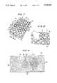
- FIG. 1is a perspective view illustrating a foam block being inserted between a pair of cylindrical rollers
- FIG. 2is an enlarged partial perspective view illustrating the fingers of the rollers of FIG. 1;
- FIG. 3is an enlarged exploded perspective view of one of the fingers of FIG. 2;
- FIG. 4is an illustration of two convoluted halves of a block after insertion into the apparatus of FIG. 1;
- FIG. 5illustrates the fit between the halves of the block of FIG. 4
- FIG. 6illustrates the topping-off of the peaks of one of the halves of FIG. 4
- FIG. 7illustrates the half of FIG. 6 after being saw cut
- FIG. 8illustrates the clip cutting of the half of FIG. 7
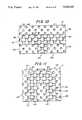
- FIG. 9is a schematic plan view illustrating the general spacing of the tail and shoulder regions of a bed pad made in accordance with the principles of the present invention.
- FIG. 10is a schematic plan view of a pillow made in accordance with the principles of the present invention illustrating the shape of the head and neck support area in phantom;
- FIG. 11is a schematic plan view of a wheelchair pad made in accordance with the principles of the present invention illustrating the shape of the buttock and thigh support area in phantom;
- FIG. 12is a perspective view of the pillow of FIG. 10;
- FIG. 13is a perspective view of the wheelchair pad of FIG. 11;
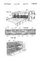
- FIG. 14is a perspective view of the bed of FIG. 9;
- FIG. 15is a sectional view taken along line 15--15 of FIG. 14 illustrating the varying valley thicknesses of the different areas of the bed pad;
- FIG. 16is a perspective view illustrating a foam block being inserted between a pair of cylindrical rollers of an alternative configuration
- FIG. 17is an enlarged partial perspective view illustrating, the fingers of the rollers of FIG. 16;
- FIG. 18is an illustration of two convoluted halves of a block after insertion into the apparatus of FIG. 16;
- FIG. 19is a perspective view of one of the halves of FIG. 18 after being saw-cut;
- FIG. 20is a sectional view taken along line 20--20 of FIG. 19 illustrating the varying valley thicknesses of the different areas of the mattress;
- FIG. 21is a perspective view illustrating a foam block being inserted between a pair of cylindrical rollers of a second alternative configuration
- FIG. 22is an enlarged partial perspective view illustrating the fingers of the rollers of FIG. 21;
- FIG. 23is an illustration of two convoluted halves of a block after insertion into the apparatus of FIG. 21;
- FIG. 24is a perspective view of one of the halves of FIG. 23 after being saw-cut.
- FIG. 25is a sectional view taken along line 25--25 of FIG. 24 illustrating the varying valley thicknesses of the different areas of the pad.
- FIG. 1shows an apparatus 11 for manufacturing convoluted foam pads.
- the apparatus 11includes a pair of cooperating parallel rollers, 13 and 14, each of which has a cylindrical body and an undulated surface.
- the undulated surface of each rolleris formed by a plurality of fingers 15 of generally rectangular cross section extending radially from its cylindrical body.
- the fingers 15are arranged in vertical and horizontal rows. Fingers in vertically adjacent rows are staggered vertically a circumferential distance approximately equal to the vertical width of the fingers. Fingers in horizontally adjacent rows are staggered horizontally a circumferential distance approximately equal to the horizontal width of the fingers.
- the rotating rollers, 13 and 14,compress and drive the foam block 19 against a cutter (a guard 17 for which is shown in FIG. 4).
- a cuttera guard 17 for which is shown in FIG. 4
- the upper rollerrotates counterclockwise and the lower rotates clockwise.
- This rotationis synchronized so the fingers 15 of the respective rollers are opposed by the spaces 21 between the fingers of the opposite roller, rather than directly by its fingers 15.
- all fingers 15 on a given side of, and vertically adjacent to, the spaces of one rollerhave an effective height equal to the effective height of the finger of the opposing roller which opposes the space.
- each of the fingers 15is equal. Selected fingers, however, have a greater effective radial height as a result of one or more flat rectangular caps 23 or plates being secured to the radial outer end of the finger by a bolt 25 threadably secured within a tapped bore 27 extending radially through the center of the finger.
- the thickness of the caps 23can be varied depending upon the given application.
- a countersink 29may be provided around the bore 27 of the outer cap, so that the head of the bolt 25 is flush with the outer face 31 of the cap.
- the foam block 19is compressed between the rollers, it is driven against the cutter (not shown) which slices the block 19 into halves 33.
- the resulting halves 33are virtually a perfect mirror image of one another, with each peak 35 of one half corresponding to an adjacent peak 37 of equal size on the other half.
- the variance in the effective height of the fingers 15results both in peaks with varying peak heights P, and valleys with varying valley floor heights V. Because the pad is cut from a single block 19, however, the sum of the valley floor height and the corresponding peak height will equal a constant, so long as the block being cut is of uniform thickness.
- the heights of the peaks 42 of the resulting foam halves 33can be varied 3-4 inches.
- the base height of the corresponding valleys 44will vary an equal amount.
- the peak to base ratio of the padcan be made to vary widely, essentially the same volume of foam is present to resist the weight of a given area of the body supported by the pad.
- the tops 39 of the peaks 42are then removed with a band saw 41 or other suitable cutting device, thereby leaving a rectangular pad 43 with a flat solid lower face 45 and a substantially flat upper face 47 comprised of the flat tops 49 of the peaks 42.
- the pad 43comprises adjacent rows of peaks 42 of generally rectangular cross section, each of which are separated by valleys 44, also of generally rectangular cross section. Since the peaks 42 in adjacent rows are staggered, the overall effect is a checkerboard pattern, with the corners of the peaks 42 in adjacent rows connected by webbing 51 extending between the peaks 42 to the floor of the valleys 44. The webbing 51 between some peaks 42 will extend from the top of the peak downward to the floor of the valley between them.
- a peak 57in a row of peaks 59 between a second and third row of peaks, 61 and 63, respectively, has a first corner 65 connected by webbing 51 to a corner of a first peak 67 in the second row 61 and a second corner 69 which is connected by webbing 51 to a corner of a second peak 71 in the second row 61.
- the peak 57has a third corner 73 which is connected by webbing 51 to a corner of a first peak 75 in the third row 63 and a fourth corner 77 which is connected by webbing 51 to a second peak 79 in the third row 63.
- the tops of the peaks 42are cut off at a point midway between the tops of the peaks 42 and the floor of the valleys 44.
- each of the remaining flat-topped peaks 42will have a uniform peak height, the base height of the valley floors varies in proportion to the effective height of the finger which created it.
- the pad 43has a flat lower face 45, the peak height of each peak is equal to its peak thickness (i.e., the vertical distance between the top of the peak and the bottom of the portion of the pad 43 directly beneath the peak).
- the lower face of the pad 43included an opening beneath the peak, this would not be the case.
- each valley of the illustrated pad 43is equal to its valley thickness (i.e., the vertical distance between the valley floor and the bottom of the portion of the pad 43 directly beneath the valley floor). If the lower face 45 of the pad 43 included an opening beneath the valley floor, however, this would not be the case.
- the pad of the present inventioncan be made from a wide variety of types of foam of varying density and thickness. It has been found, however, that the desired combination of cushioning and support is obtained from an open cell expanded plastic polyurethane foam with a density of between one and three pounds per cubic foot, preferably 1.5 pounds.
- the peak and valley thickness of the pad 43is desirably sufficient to ensure that the body supported by the pad does not bottom out. For a bed pad 43 having a density of between 1-3 pounds, a peak thickness of between 3-5 inches, and a valley thickness of approximately one half of an inch has been found to be sufficient to prevent bottoming out in most instances.
- FIG. 9there is shown a schematic view of a bed pad 43 manufactured in accordance with the principles of the present invention.
- the bed pad 43will generally have an overall length of between 60-90 inches and a width of between 25-40 inches, depending upon the length and width of the mattress being covered. For specialty beds, the length could vary between 30-90 inches and the width could vary between 20-90 inches.
- the illustrated pad 43has a length of approximately 72 inches and a width of approximately 35 inches.
- the shoulder support area 81 and tail support area 83 of the pad 43are positioned to correspond to the normal position of the shoulder and tail portions of the body of the intended user and are surrounded by the general support area 84 of the pad 43.
- the shoulder support area 81 of the illustrated pad 43is spaced twelve inches from one end 85 of the pad, is centered between the sides 87 of the pad and has a width of 28.35 inches and a length of 14.85 inches.
- the width and length of the shoulder support area 81, as well as its shapemay vary, but preferably the width is between 25 and 33 inches, the length is between 12 and 17 inches and the shape is generally that of a mushroom.
- the tail support area 83 of the illustrated pad 43is elliptical in shape, is centered between the sides of the pad, has a width of 17.55 inches and a length of 12.15 inches. This spaces the tail support area 27 inches from the other end 89 of the pad.
- the width and length of the tail support area 83may vary, but preferably, the width is between 15 and 20 inches, the length is between 10 and 17 inches, and the area is generally elliptical or circular in shape. Naturally, an additional support area could be added for the heels, if desired.
- the illustrated padhas a uniform distribution of peaks of square cross section.
- the peaks 42 of the general support area, the shoulder support area 81 and the tail support area 83all have a peak thickness of 4 inches and a square cross section with a width of 1.35 inches.
- the valley thicknesses of the shoulder and tail support sections of the padare less than the valley thicknesses of the general support area of the pad.
- the valley thickness for both the shoulder support area 81 and the tail support area 83is one half of one inch, while the valley thickness for the general support area is 3 inches.
- the bed pad 43is formed by means of inserting a block 19 of foam lengthwise through a roller having a circumference equal to the length of the bed pad 43, so that a pair of pads is formed by a single turn of the roller.
- the illustrated pad 43would be formed with two rollers each having a circumference of 72 inches.
- the fingers 15 of each roller corresponding to the general support area of the pad 43advantageously extend radially 2.5 inches from the cylindrical core of the roller and have a square cross section with a width of 0.9 inches. This width may vary, but is preferably between 1.25 and 2.0 inches.
- the space between the opposing rollers, 13 and 14,is roughly one quarter of an inch, with this distance being shortened where the rollers are provided with caps.
- the fingers 15 of the roller corresponding to the shoulder support area 81 and the tail support area 83are advantageously formed by fingers 15 with an effective finger height of 2.6875 inches, resulting from the placing of caps 23 having a combined thickness of 3/16 of an inch onto the end of the fingers 15.
- the resulting bed pad 43is 4 inches thick with a valley thickness of 0.5 inches which is sufficient to prevent bottoming out in most cases.
- the bed pad of the present inventionIn a test comparing a bed pad, generally conforming to the specifications set forth above, with static water, static air and other convoluted foam support pads, the bed pad of the present invention not only demonstrated pressure relief capabilities, in the scapulae, sacrum and trochanter areas, superior to the other convoluted foam bed pads tested, but demonstrated pressure redistribution capabilities in these areas comparable to the static air and water support pads tested.
- the pads testedare as follows:
- the method and teachings of the present inventioncan be used to manufacture pads of a wide variety of shapes and sizes. Specifically, the method of the present invention can be used to manufacture pillows and wheelchair pads which conform to the shape of the body, thereby increasing the total surface area of the pad resisting the body weight of the user.
- FIGS. 10 and 12show a pillow 93 having a generally T-shaped head and neck support area 95 and a general support area 97.
- the pillow 93is formed by peaks 99 arranged in rows, wherein each peak has a flat top, is spaced from any adjacent peak in the same row by a valley 101 and has generally identical peak thicknesses.
- the tops of the peaksare all in substantially the same plane, thereby providing a pillow 93 of pleasing appearance which can be used with standard pillow covers.
- the average valley thickness of the head and neck support area 95is less than the average valley thickness of the general support area 97.
- the illustrated pillow 93has a width of 21 inches and a depth of 14 inches, with a uniform peak thickness of 4 inches.
- the truncated stem 103 of the T-shaped head and neck support area 95extends toward the center of the pillow 93 from one end 105, is centered between the sides 106 of the pillow and has a width of 4.05 inches.
- the crossbar 107 of the T-shaped head and neck support area 95extends from one side of the pillow to the other, is spaced 4.05 inches from the end of the pillow from which the stem portion extends, and has a depth of 4.05 inches. This spaces the stem portion 5.90 inches from the opposite end 111 of the pillow.
- the desired contouring effectmay be obtained from a T-shaped head and neck support area 95 with an average valley thickness of 1/2 an inch and the general support area 97 with a uniform valley thickness of 3 inches.
- FIGS. 11 and 13show a wheelchair pad 113 having a generally U-shaped buttock and thigh support area 115 and a general support area 117.
- the wheelchair pad 113is formed by peaks 119 arranged in rows, wherein each peak has a flat top, is spaced from any adjacent peak in the same row by a valley 121 and has generally identical peak thickness.
- the tops of the peaksare also all in substantially the same plane, thereby providing a wheelchair pad 113 of pleasing appearance.
- the average valley thickness of the buttock and thigh support area 115is less than the average valley thickness of the general support area 117.
- the illustrated wheelchair pad 113has a width of 18 inches and a depth of 16 inches, with a uniform peak thickness of 41/2 inches.
- the legs 123 of the T-shaped buttock and thigh support area 115extend toward the opposite end of the wheelchair pad from one end, are spaced 2.295 inches from the sides of the wheelchair pad and have a width of 4.05 inches.
- An arcuate connecting portion 125connects the two legs of the U-shaped buttock and thigh support area 115, is spaced 11/4 inches from the opposite end of the wheelchair pad, and has a width of 4.05 inches.
- the desired contouring effectmay be obtained from a U-shaped buttock and thigh support area 115 with an average valley thickness of 3/4 inches and the general support area 117 with a uniform valley thickness of 31/2 inches.
- the method and teachings of the present inventioncan be used to manufacture an anatomically, conformable convoluted foam pad, particularly adapted to be used as a mattress, rather than a mattress overlay.
- FIG. 16shows an apparatus 126 for manufacturing convoluted foam mattresses.
- the apparatus 127includes a pair of cooperating parallel rollers 127 and 129, each of which has a central undulated surface 131 and a cylindrical body 133, including a pair of ends, 135 and 137. As shown in FIGS. 16 and 17, at each end of the roller is an exposed cylindrical surface 139.
- the undulated surface 131 of each rolleris formed by a plurality of fingers 141 of generally rectangular cross-section extending radially from its cylindrical body 133.
- the fingers 141 in vertically adjacent rowsare staggered vertically a circumferential distance approximately equal to the vertical width of the fingers 141, and fingers 141 in horizontally adjacent rows are staggered horizontally a circumferential distance approximately equal to the horizontal width of the fingers 141.
- the rotating rollers, 127 and 129compress and drive a foam block 143 against the cutter (a guard 144 for which is shown in FIG. 18).
- the upper roller 127rotates counterclockwise and the lower roller 129 rotates clockwise in a synchronized manner so that the fingers 141 of the respective rollers are opposed by the spaces between the fingers of the opposite roller.
- the cylindrical surfaces 139 of the ends, 135 and 137 of the upper roller 127are opposed by the cylindrical surfaces 139 of the respective ends, 135 and 137, of the opposite roller 129.
- All fingers 141 on a given side of, and vertically adjacent to, the spaces of one rollerhave an effective height equal to the effective height of the finger of the opposing roller which opposes the space. As shown in FIG. 17, the radial height of most of the fingers 141 is equal. Selected fingers 141, however, have a greater effective radial height as a result of one or more flat, rectangular caps 145 or plates being secured to the outer end of the finger.
- each rollercompress the foam in identical amount, so that the portion of the block 143 compressed between the cylindrical surfaces 139 of the rollers is flat, with each portion of the mattress corresponding to the cylindrical surface of the ends of the rollers forming an elongate rail 153 of identical thickness extending the length of the mattress.
- tops of the peaks formed by the cooperating undulating surfacesare then removed with a band saw or other suitable cutting device at a point midway between the tops of the peaks and the floor of the valleys, in the manner illustrated in FIG. 6, leaving an elongate rectangular mattress 155 (FIG. 19-20) with a flat, solid, lower face 157 and a substantially flat, upper face 159 comprised of the flat tops of a plurality of peaks 161 and a pair of elongate rails 153 extending the length of the mattress.
- the portion of the mattress between the rails 153comprises adjacent rows of peaks 161 of generally rectangular cross-section, each of which are separated by a plurality of valleys 162, also generally rectangular cross-section. Since the peaks 161 in adjacent rows are staggered, the overall effect is a checker-board pattern with two flat elongate borders formed by the mattress' two rails 153.
- the mattress 155 manufactured in accordance with the principles of the present inventiondesirably has a thickness in excess of 5 inches, an overall length of between 30 and 90 inches and an overall width of between 20 and 90 inches, depending upon the length and width of the bed frame, and the length and width of the box springs being utilized.
- the lengthcould vary between 30-90 inches and the width could vary between 20-90 inches.
- the flat rails 153 of the mattress 155desirably have a width of between 2 and 6 inches and may extend over any portion of the length of the mattress, but desirably at least half of the mattress' length and, preferably, the entire length of the mattress.
- the rails 153have a greater volume of foam per unit area, and provide an area of increased resistance, to provide support when getting on to or off of the mattress.
- the rails 153have a width of 3 inches and extend the length of the mattress.
- the illustrated mattresshas a length of approximately 72 inches and a width of approximately 35 inches.
- a mattress manufactured in accordance with the principles of the present inventioncan alternatively be designed so that breaks in the flat rails are positioned to correspond with the hinge points about which most hospital beds are bendable. Such breaks in the flat rails, if configured to the same peak and valley dimensions of the general support area of the mattress make the mattress easier to bend with the hinged bed at that point.
- the general support area 163Between the mattress rails 153 is a general support area 163.
- the general support areasurrounds a shoulder support area 165 and a tail support area 167 which are positioned to correspond to the normal position of the shoulder and tail portions of the body of the intended user.
- the shoulder support area 165 of the illustrated mattressis spaced 12 inches from one end of the pad, it is centered between the sides of the mattress and has a width of 28.35 inches and a length of 14.85 inches.
- the width and length of the shoulder support area 165, as well as its shapemay vary, but preferably the width is between 25 and 33 inches, the length is between 12 and 17 inches and the shape is generally that of a mushroom.
- the tail support area 167 of the illustrated mattressis elliptical in shape, it is centered between the sides of the mattress and has a width of between 17.55 inches and a length of 12.15 inches This spaces the tail support area 167 27 inches from the other end of the mattress.
- the width and length of the tail support area 167, as well as its shape,may vary, but preferably, the width is between 15 and 20 inches, the length is between 10 and 17 inches, and the area is generally elliptical or circular in shape.
- a longer foam blockin manufacturing the mattress, so as to take advantage of the difference between the circumference of the rollers, 127 and 129, and the length of the block. As will be readily appreciated, this will result in a greater angular rotation of the rollers, 127 and 129, to cause, for example, a repeat of the shoulder support area pattern.
- a portion of the shoulder support areacan be designed to provide for an additional heel support area running approximately 2/3 of the distance across the pad involving up to the last 12" of the pad. Such a heel support area would provide a general softening of this portion of the pad and accommodate the heels and bones of the lower leg.
- the illustrated mattresspossesses a flat, rectangular overall configuration, it may be difficult to determine its correct head-to-foot end orientation if covered in a permanent upholstered cover. To mitigate this potential problem, in such instances, it may be desirable to use the principles of the present invention to provide a second shoulder support area at the opposite end of the block from the first shoulder support area, so that the first and second shoulder support areas are symmetrical about the tail support area.
- This modificationprovides the same general shoulder and tail support for the body without regard for head-to-foot end orientation.
- This modificationprovides the same general shoulder and tail support for the body without regard for head-to-foot end orientation.
- because of the lack of body mass and projection in the general area of the back or side of the kneesthere is very little increased deformation in the area of the unused shoulder support area and, no significant change in the pressures recorded at the primary bony prominent areas of the body.
- the convoluted portion of the illustrated mattresshas a uniform distribution of peaks of square cross-section.
- the peaks 161 of the general support area 163, the shoulder support area 165 and the tail support area 167all have a peak thickness of 6 inches in a square cross-section with a width of 1.35 inches.
- the valley thicknesses of the shoulder and tail support sections, 165 and 167, of the mattressare less than the valley thicknesses of the general support area 163 of the mattress.
- the valley thickness for both the shoulder support area 165 and the tail support area 167is 1/2 of one inch while the valley thickness for the general support area is 3 inches.
- the principles of the present inventioncan be used to manufacture an anatomically conforming bed overlay or posturizer for home health care applications.
- FIG. 21shows an apparatus 169 for manufacturing convoluted foam posturizers.
- the apparatusincludes a pair of cooperating rollers, 171 and 173, each of which has a cylindrical body 175.
- Each rollerincludes three sections 176 having an undulated surface and a pair of sections 177 formed by rows of ribs.
- the undulated surface of each rolleris formed by a plurality of fingers 179 of generally rectangular cross-section extending radially from its cylindrical body 175.
- the fingers 179are arranged in vertical and horizontal rows.
- the fingers 179 in vertically adjacent rowsare staggered vertically a circumferential distance approximately equal to the vertical width of the fingers.
- Fingers 179 in horizontally adjacent rowsare staggered horizontally a circumferential distance approximately equal to the horizontal width of the fingers.
- the ribbed sections 177are formed by vertically spaced ribs 181, each of which extends the length of the section and extends radially outward from the cylindrical body 175 of the roller.
- the ribs 181are spaced vertically from one another, a circumferential distance approximately equal to the vertical width of the ribs 181.
- the rollers 171 and 173are configured so that when the side of a foam block 183 is inserted between the rollers, the rollers, 171 and 173, form a constant pattern, regardless of the width of the block 183. This enables the same rollers to be utilized to form posturizers having a width corresponding to a twin, queen or king-size bed.
- the rotating rollers 171 and 173compress and drive the foam block 183 against a cutter (a guard 185 for which is shown in FIG. 23).
- the upper roller 171rotates counterclockwise and the lower roller 173 rotates clockwise. This rotation is synchronized so that the fingers 179 of the respective rollers are opposed by the spaces between the fingers of the opposite roller, rather than directly by its fingers 179.
- the ribs 181 of the upper roller 171are opposed by the spaces between the ribs 181 of the lower roller 173, rather than directly by its ribs 181.
- the effective height of each of the fingers 179is equal and the radial height of each of the ribs 181 is equal, although the effective height of each of the ribs 181 is greater than the effective height of each of the fingers 179.
- each peak 189 of one halfcorresponding to an adjacent peak 189 of equal size on the other half
- each rib 191 of one halfcorresponding to an adjacent rib 191 of equal size on the other half. Since the effective height of each of the fingers 179 is equal, each peak 189 has an identical peak height and each valley 193 has an identical valley thickness. Likewise, since the effective height of each of the ribs 177 is equal, each rib 191 of the posturizer has an identical peak height and each valley has an identical valley thickness.
- tops of the peaks and ribsare removed with a band saw or other suitable cutting device at a point midway between the tops of the peaks and the floor of the valleys leaving an elongate rectangular posturizer 195 (FIG. 24-25) with a flat, solid, lower surface 197 and a substantially flat, upper surface 199 comprised of the flat tops of the peaks 189 and the flat tops of the ribs 191. As shown in FIG.
- the posturizeris formed by a head support area 201 adjacent one of the ends of the posturizer for supporting the head of a body, a shoulder support area 203 adjacent the head support area 201 for supporting the shoulder portion of a body, a middle back support area 205 adjacent the shoulder support area 203 for supporting the middle back portion of a body, a tail support area 207 adjacent the middle back support area 205 for supporting the tail section of a body and a leg and feet support area 209 adjacent the tail support area 207 and the other end of the posturizer for supporting the legs and feet of a body.
- the head support area 201, the middle back support area 205 and the leg and feet support area 209are formed by adjacent rows of peaks 213 of generally rectangular cross-section, each of which are separated by valleys 215, also of generally rectangular cross-section.
- the overall affect of the peaks and valleysis a checkerboard pattern, with the corners of the peaks 213 in adjacent rows connected by webbing extending between the peaks to the floor of the valleys 215.
- the shoulder support area 203 and the tail support area 207are formed by rows of horizontally spaced longitudinally extending ribs 217, wherein each rib is separated from the adjacent rib 217 by a longitudinally extending valley 219.
- the overall affect of the ribs and valleysis a corrugated pattern.
- the effective height of the fingers which corresponded to the areas of the pad supporting the shoulder and tail sections of the bodyhave been increased to form taller peaks and lower valleys in those areas of the pad.
- topping off the peaks at a certain heightone was left with a smaller volume of foam to resist the weight of that portion of the body.
- the ribs 181 of the rollersSince the effective height of the ribs 181 of the rollers is greater than the effective height of the fingers 179, the ribs have a greater peak height and valleys of lower valley thickness than the peaks and valleys formed by the fingers.
- the shoulder and tail support areas, formed by the rows of ribs 217 and valleys 219After the tops of the ribs and peaks are removed, the shoulder and tail support areas, formed by the rows of ribs 217 and valleys 219, have a lower foam content (i.e., a smaller amount of foam of uniform density per unit volume) than the head, middle back and leg and feet support areas 201, 205, and 209, respectively, formed by the adjacent rows of peaks 213 and valleys 215.
- the shoulder and tail portions of the bodyare more able to overcome the resistance of the posturizer and sink into the shoulder and tail support areas 203 and 207, thereby increasing the surface area of the posturizer in contact with the shoulder and tail portion of the body and diminishing the level of pressure exerted on the skin per unit area.
- the shoulder and tail portion of the bodyprotrude farther into the shoulder and tail support areas, 203 and 207, of the pad, the pressure of the head, middle back and leg and feet support areas 201, 205 and 209 on the less protruding portions (e.g., the side) will increase, thereby relieving pressure from the tail and shoulder portions of the body.
- the anatomically conforming posturizer 195will generally have an overall length of between 60-90 inches and a width of between 25-40 inches, depending upon the length and width of the mattress being covered, and a thickness of between 1-3 inches. Further, for specialty beds, the length may vary between 30-90 inches and the width may vary between 20-90 inches.
- the illustrated posturizer 195has a length of approximately 72 inches and a width of approximately 35 inches.
- the leg and feet support area 209has a length of approximately 29 inches.
- the tail support area 207has a length of approximately 11 inches.
- the middle back support area 205has a length of approximately 9 inches.
- the shoulder support area 203has a length of approximately 15 inches, and the head support area 201 has a length of approximately 9 inches.
- the posturizerhas a thickness of 2 inches and, therefore, a uniform peak height of 2 inches, a valley thickness of 1/4 inch in the shoulder and tail support areas 203 and 207, and a valley thickness of 11/4 inches in the head, middle back and leg and feet support areas 201, 205 and 209.
- the length and thickness of the support areasmay vary depending upon the average size of the body to be supported.
Landscapes
- Engineering & Computer Science (AREA)
- Mechanical Engineering (AREA)
- Mattresses And Other Support Structures For Chairs And Beds (AREA)
- Invalid Beds And Related Equipment (AREA)
Abstract
Description
______________________________________ Model Designation Manufacturer Trademark No. Type ______________________________________ Foam #1* Pre-Foam, Inc. HIGHFLOAT 5095020 foam Water Lotus Health- LOTUS HM3666 water care Products Air Gaymar SOF.CARE SC-402 air Industries, Inc. Foam #2 Bio Clinic BIOGARD 669030 foam Company Foam #3 Span America GEO-MATT 50960-581 foam Medical Systems, Inc. Foam #4 Pre-Foam, Inc. PREVENT P141 foam ______________________________________ *Foam Pad #1 is a pad made in accordance with the principles of the present invention.
______________________________________ Pressure Level Pad Scapulae Sacrum Trochanter Designation (mm Hg) (mm Hg) (mm Hg) ______________________________________ Foam #1* 24.02 28.28 44.22 Water 22.44 25.96 46.74 Air 32.36 33.15 40.57 Foam #2 29.26 34.40 47.17 Foam #3 23.04 31.97 49.73 Foam #4 28.04 36.88 45.97 ______________________________________
Claims (13)
Priority Applications (6)
| Application Number | Priority Date | Filing Date | Title |
|---|---|---|---|
| US07/176,925US4879776A (en) | 1988-04-04 | 1988-04-04 | Anatomically conformable foam support pad |
| US07/328,236US5038433A (en) | 1988-04-04 | 1989-03-24 | Anatomically conformable foam support pad |
| CA000595514ACA1322424C (en) | 1988-04-04 | 1989-04-03 | Anatomically conformable foam support pad |
| US07/411,051US5010609A (en) | 1988-04-04 | 1989-09-22 | Anatomically conformable foam support pad |
| US07/641,447US5178811A (en) | 1988-04-04 | 1991-01-14 | Method of forming an anatomically conformable foam support pad |
| US07/691,480US5077849A (en) | 1988-04-04 | 1991-04-24 | Anatomically conformable foam support pad |
Applications Claiming Priority (6)
| Application Number | Priority Date | Filing Date | Title |
|---|---|---|---|
| US07/176,925US4879776A (en) | 1988-04-04 | 1988-04-04 | Anatomically conformable foam support pad |
| US07/328,236US5038433A (en) | 1988-04-04 | 1989-03-24 | Anatomically conformable foam support pad |
| US38464189A | 1989-07-21 | 1989-07-21 | |
| US07/411,051US5010609A (en) | 1988-04-04 | 1989-09-22 | Anatomically conformable foam support pad |
| US07/641,447US5178811A (en) | 1988-04-04 | 1991-01-14 | Method of forming an anatomically conformable foam support pad |
| US07/691,480US5077849A (en) | 1988-04-04 | 1991-04-24 | Anatomically conformable foam support pad |
Related Child Applications (1)
| Application Number | Title | Priority Date | Filing Date |
|---|---|---|---|
| US07/691,480DivisionUS5077849A (en) | 1988-04-04 | 1991-04-24 | Anatomically conformable foam support pad |
Publications (1)
| Publication Number | Publication Date |
|---|---|
| US5038433Atrue US5038433A (en) | 1991-08-13 |
Family
ID=43379018
Family Applications (5)
| Application Number | Title | Priority Date | Filing Date |
|---|---|---|---|
| US07/176,925Expired - LifetimeUS4879776A (en) | 1988-04-04 | 1988-04-04 | Anatomically conformable foam support pad |
| US07/328,236Expired - LifetimeUS5038433A (en) | 1988-04-04 | 1989-03-24 | Anatomically conformable foam support pad |
| US07/411,051Expired - LifetimeUS5010609A (en) | 1988-04-04 | 1989-09-22 | Anatomically conformable foam support pad |
| US07/641,447Expired - LifetimeUS5178811A (en) | 1988-04-04 | 1991-01-14 | Method of forming an anatomically conformable foam support pad |
| US07/691,480Expired - LifetimeUS5077849A (en) | 1988-04-04 | 1991-04-24 | Anatomically conformable foam support pad |
Family Applications Before (1)
| Application Number | Title | Priority Date | Filing Date |
|---|---|---|---|
| US07/176,925Expired - LifetimeUS4879776A (en) | 1988-04-04 | 1988-04-04 | Anatomically conformable foam support pad |
Family Applications After (3)
| Application Number | Title | Priority Date | Filing Date |
|---|---|---|---|
| US07/411,051Expired - LifetimeUS5010609A (en) | 1988-04-04 | 1989-09-22 | Anatomically conformable foam support pad |
| US07/641,447Expired - LifetimeUS5178811A (en) | 1988-04-04 | 1991-01-14 | Method of forming an anatomically conformable foam support pad |
| US07/691,480Expired - LifetimeUS5077849A (en) | 1988-04-04 | 1991-04-24 | Anatomically conformable foam support pad |
Country Status (1)
| Country | Link |
|---|---|
| US (5) | US4879776A (en) |
Cited By (53)
| Publication number | Priority date | Publication date | Assignee | Title |
|---|---|---|---|---|
| US5134735A (en)* | 1990-11-05 | 1992-08-04 | E. R. Carpenter Company, Inc. | Mattress cushion with multiple zones |
| FR2684530A1 (en)* | 1991-12-04 | 1993-06-11 | Wine Douglas | MATTRESSES INTENDED TO BE LAID ON EXISTING BEDDING. |
| USD337913S (en) | 1992-06-18 | 1993-08-03 | E. R. Carpenter Company, Inc. | Mattress cushion |
| DE4305177A1 (en)* | 1993-02-19 | 1994-08-25 | Kirchhoff Guenther | Anatomically designed mattress |
| USD352858S (en) | 1993-05-10 | 1994-11-29 | Farley David L | Anatomically conformable support pad |
| US5430901A (en)* | 1993-06-10 | 1995-07-11 | Farley; David L. | Anatomically conformable therapeutic mattress overlay |
| WO1997019619A1 (en) | 1995-11-30 | 1997-06-05 | Sleep Options, Inc. | Mattress structure |
| USD381543S (en)* | 1994-10-27 | 1997-07-29 | Farley David L | Foam pad |
| USD383349S (en)* | 1996-07-12 | 1997-09-09 | Carpenter Company | Cushion pad |
| WO1997043927A1 (en) | 1996-05-24 | 1997-11-27 | Hill-Rom, Inc. | Mattress structure having a foam mattress core |
| US5974609A (en)* | 1998-06-29 | 1999-11-02 | The Spring Air Company | Quilt top mattress with convoluted foam cushion |
| US6003179A (en)* | 1997-11-18 | 1999-12-21 | Farley; David L. | Inclined anatomic support surface |
| US6041459A (en)* | 1997-10-03 | 2000-03-28 | The Spring Air Company | Convoluted foam cushion |
| US6115861A (en)* | 1997-10-09 | 2000-09-12 | Patmark Company, Inc. | Mattress structure |
| USD433861S (en)* | 1999-08-31 | 2000-11-21 | Carpenter Co. | Support pad |
| US20030150061A1 (en)* | 2001-12-20 | 2003-08-14 | Farley David L. | Independent foam cell surface and method of making same |
| US6701557B2 (en)* | 2001-11-29 | 2004-03-09 | Sealy Technology Llc | Single piece foam toppers with perimeter areas having variable support and firmness properties |
| US7690096B1 (en) | 2008-09-19 | 2010-04-06 | Dreamwell, Ltd. | Method of manufacturing an aged mattress assembly |
| US20100269262A1 (en)* | 2009-04-24 | 2010-10-28 | Foamex L.P. | Mattress adapted for supporting heavy weight persons |
| US20100330316A1 (en)* | 2009-06-25 | 2010-12-30 | Nomaco Inc. | Self-adjusting insulation, including insulation particularly suited for pipe or duct |
| US20110072587A1 (en)* | 2009-09-29 | 2011-03-31 | Nomaco Inc. | Foam cushion having reduced cross-section area foam profiles forming hollow portion(s) for deformation |
| US7941883B2 (en)* | 2005-06-29 | 2011-05-17 | Seating Design and Development Limited | Therapeutic mattress |
| US20110154576A1 (en)* | 2009-04-24 | 2011-06-30 | Foamex Innovations Operating Company | Mattress adapted for supporting heavy weight persons |
| USD688069S1 (en) | 2012-09-28 | 2013-08-20 | Noel Group Llc | Mattress bed cushion |
| USD688492S1 (en) | 2010-03-03 | 2013-08-27 | Noel Group Llc | Mattress bed cushion |
| USD690536S1 (en) | 2012-07-26 | 2013-10-01 | Nomaco Inc. | Motion isolation insulator pad |
| USD691401S1 (en) | 2009-03-06 | 2013-10-15 | Noel Group, Llc | Mattress bed cushion |
| USD691400S1 (en) | 2012-02-10 | 2013-10-15 | Nomaco Inc. | Stackable base for mattress assembly |
| USD692692S1 (en) | 2011-04-29 | 2013-11-05 | Noel Group Llc | Mattress bed cushion |
| USD692693S1 (en) | 2012-04-27 | 2013-11-05 | Noel Group Llc | Mattress bed cushion |
| USD692694S1 (en) | 2012-09-28 | 2013-11-05 | Noel Group Llc | Mattress bed cushion |
| USD693147S1 (en) | 2012-04-27 | 2013-11-12 | Noel Group Llc | Mattress bed cushion |
| USD693145S1 (en) | 2010-03-03 | 2013-11-12 | Noel Group Llc | Mattress bed cushion |
| USD693146S1 (en) | 2012-04-27 | 2013-11-12 | Noel Group Llc | Mattress bed cushion |
| USD693144S1 (en) | 2010-03-03 | 2013-11-12 | Noel Group Llc | Mattress bed cushion |
| USD693149S1 (en) | 2012-04-27 | 2013-11-12 | Noel Group Llc | Mattress bed cushion |
| USD693148S1 (en) | 2010-03-03 | 2013-11-12 | Noel Group Llc | Mattress bed cushion |
| US8584286B2 (en) | 2010-04-27 | 2013-11-19 | Ec Service Inc. | Systems and methods for providing a self deflating cushion |
| USD694041S1 (en) | 2012-09-28 | 2013-11-26 | Noel Group Llc | Mattress bed cushion |
| USD694553S1 (en) | 2010-03-03 | 2013-12-03 | Noel Group Llc | Mattress bed cushion |
| USD694552S1 (en) | 2012-04-27 | 2013-12-03 | Noel Group Llc | Mattress bed cushion |
| USD697337S1 (en) | 2012-07-03 | 2014-01-14 | Nomaco, Inc. | Stackable base for mattress assembly |
| USD701713S1 (en) | 2012-11-09 | 2014-04-01 | Noel Group, Llc | Mattress bed cushion |
| USD704962S1 (en) | 2013-09-09 | 2014-05-20 | Noel Group Llc | Mattress bed cushion |
| USD707467S1 (en) | 2012-11-09 | 2014-06-24 | Noel Group Llc | Mattress bed cushion |
| USD707468S1 (en) | 2012-11-09 | 2014-06-24 | Noel Group Llc | Mattress bed cushion |
| USD709301S1 (en) | 2012-11-09 | 2014-07-22 | Noel Group Llc | Mattress bed cushion |
| US8789224B2 (en) | 2000-11-07 | 2014-07-29 | Tempur-Pedic Managemant, LLC | Therapeutic mattress assembly |
| US9157566B2 (en) | 2012-05-11 | 2015-10-13 | Nomaco Inc. | Insulation systems employing expansion features to insulate elongated containers subject to extreme temperature fluctuations, and related components and methods |
| US20160338499A1 (en)* | 2015-05-21 | 2016-11-24 | Global Medical Foam, Inc. | Customizable Pressure Offloading Cushioning Device |
| US10045633B2 (en) | 2013-04-26 | 2018-08-14 | Noel Group Llc | Cushioning assemblies with thermoplastic elements encapsulated in thermoset providing customizable support and airflow, and related methods |
| US11311438B2 (en) | 2015-05-21 | 2022-04-26 | Global Medical Foam, Inc. | Customizable pressure offloading cushioning device |
| US11583100B2 (en) | 2019-09-11 | 2023-02-21 | Global Medical Foam, Inc. | Customizable pressure offloading cushioning device with variable flexibility |
Families Citing this family (89)
| Publication number | Priority date | Publication date | Assignee | Title |
|---|---|---|---|---|
| US4835802A (en)* | 1988-02-22 | 1989-06-06 | The Kmw Group, Inc. | Fluidization patient support control system |
| US4879776A (en)* | 1988-04-04 | 1989-11-14 | Farley David L | Anatomically conformable foam support pad |
| US5111542A (en)* | 1988-04-04 | 1992-05-12 | Farley David L | Anatomically conformable foam support pad |
| USD326204S (en) | 1989-01-11 | 1992-05-19 | Main Ewan J | Mattress pad |
| USD323092S (en) | 1989-07-05 | 1992-01-14 | E. R. Carpenter Company, Inc. | Mattress overlay |
| US5031261A (en)* | 1990-03-15 | 1991-07-16 | E. R. Carpenter Company, Inc. | Mattress overlay for avoidance of decubitus ulcers |
| US4999868A (en)* | 1990-05-11 | 1991-03-19 | Eugene Kraft | Varying firmness mattress |
| AU8664891A (en)* | 1990-11-13 | 1992-06-11 | Leggett & Platt, Incorporated | Bedding system |
| USD329566S (en) | 1991-06-11 | 1992-09-22 | E.R. Carpenter Company, Inc. | Pillow |
| US5160785A (en)* | 1991-06-11 | 1992-11-03 | E. R. Carpenter Company, Inc. | Padding body |
| US5179742A (en)* | 1991-11-01 | 1993-01-19 | Stryker Corporation | Pressure reduction mattress |
| US5294181A (en)* | 1992-01-07 | 1994-03-15 | E. R. Carpenter Company, Inc. | Seat cushion |
| USD345072S (en) | 1992-01-07 | 1994-03-15 | E. R. Carpenter Company, Inc. | Seat cushion |
| US5327597A (en)* | 1992-07-02 | 1994-07-12 | Michael Rothbard | Convoluted mattress pad having multiple proximate peaks |
| US5523144A (en)* | 1992-10-07 | 1996-06-04 | Valwhat Enterprises, Inc. | Bedding structure with quilted-in lumbar support |
| US5599290A (en) | 1992-11-20 | 1997-02-04 | Beth Israel Hospital | Bone fracture prevention garment and method |
| AU715211B2 (en)* | 1993-06-10 | 2000-01-20 | David L. Farley | Anatomically conformable therapeutic mattress overlay |
| US8025964B2 (en)* | 1994-06-03 | 2011-09-27 | Tempur World, Llc | Laminated visco-elastic support |
| US5705252A (en)* | 1995-01-05 | 1998-01-06 | Cascade Designs, Inc. | Expanded foam products and methods for producing the same |
| US5642546A (en)* | 1995-09-19 | 1997-07-01 | Select Comfort Corporation | Inflatable mattress with improved border support wall |
| US6052851A (en)* | 1996-02-08 | 2000-04-25 | Kohnle; Robert C. | Mattress for minimizing decubitus ulcers |
| US6099776A (en)* | 1996-05-18 | 2000-08-08 | Firma Carl Freudenberg | Method of forming a flexible, open-pored cleaning body |
| DE29700100U1 (en)* | 1997-01-07 | 1997-03-13 | Dunlop GmbH Div. Dunlopillo, 63450 Hanau | Mattress made of elastic material |
| US6093468A (en) | 1997-03-14 | 2000-07-25 | The Procter & Gamble Company | Flexible lightweight protective pad with energy absorbing inserts |
| NL1007212C2 (en) | 1997-10-06 | 1999-04-08 | Recticel Nederland Bv | A method of manufacturing a body supporting element and such a body supporting element. |
| US6579158B2 (en) | 1997-11-04 | 2003-06-17 | Firma Carl Freudenberg | Flexible, open-pored cleaning body |
| US6422933B1 (en) | 1997-11-04 | 2002-07-23 | Firma Carl Freudenberg | Flexible, open-pored cleaning body |
| USD400385S (en) | 1998-02-09 | 1998-11-03 | Hudson Gary C | Varicolored convoluted mattress pad |
| USD416426S (en) | 1998-10-16 | 1999-11-16 | Foamex L.P. | Mattress overlay |
| USD416740S (en)* | 1998-10-16 | 1999-11-23 | Foamex L.P. | Mattress overlay |
| USD416739S (en)* | 1998-10-16 | 1999-11-23 | Foamex L.P. | Mattress overlay |
| USD416741S (en)* | 1998-10-16 | 1999-11-23 | Foamex L.P. | Mattress overlay |
| USD419356S (en)* | 1998-10-16 | 2000-01-25 | Foamex L.P. | Mattress overlay |
| USD417355S (en) | 1998-10-16 | 1999-12-07 | Foamex L.P. | Mattress overlay |
| USD426739S (en)* | 1999-03-12 | 2000-06-20 | Federal Foam Technologies, Inc. | Futon mattress |
| US6450886B1 (en)* | 1999-04-09 | 2002-09-17 | Konami Co., Ltd. | Foot switcher, foot switch sheet and mat for use in the same |
| US6866915B2 (en)* | 2000-01-11 | 2005-03-15 | Tempur World, Llc | Cushion |
| US6574814B2 (en) | 2000-03-14 | 2003-06-10 | L&P Property Management Company | Bedding or seating product having filled tube topper |
| IES20010867A2 (en)* | 2000-09-29 | 2002-04-17 | Lancastria Ltd | A mattress |
| US20100247856A1 (en)* | 2001-08-27 | 2010-09-30 | Vito Robert A | Vibration dampening material and method of making same |
| US8545966B2 (en)* | 2001-08-27 | 2013-10-01 | Matscitechno Licensing Company | Vibration dampening material and uses for same |
| US6829799B2 (en) | 2003-04-04 | 2004-12-14 | Paul J. Kuhn | Ischial tuberosity pressure relief cushion |
| US20110076663A1 (en)* | 2003-08-18 | 2011-03-31 | Retail Optimization International | Systems and methods for selecting survey questions and available responses |
| US7748066B2 (en)* | 2003-09-26 | 2010-07-06 | Dreamwell, Ltd. | Mattress center ridge compensator |
| AR046421A1 (en)* | 2003-10-14 | 2005-12-07 | Dreamwell Ltd | METHOD AND SYSTEM FOR THE MANUFACTURE OF A MATTRESS. |
| US9152624B1 (en) | 2003-12-04 | 2015-10-06 | Retail Optimization International, Inc. | Systems and methods for visual presentation and navigation of content using data-based image analysis |
| USD527564S1 (en)* | 2004-02-13 | 2006-09-05 | Foamex L.P. | Mattress pad |
| USD523277S1 (en)* | 2004-02-13 | 2006-06-20 | Foamex L.P. | Mattress topper |
| US7293311B2 (en)* | 2004-03-04 | 2007-11-13 | Spring Air West, L.L.C. | Method of making a multilayered mattress component |
| USD517848S1 (en)* | 2004-03-25 | 2006-03-28 | Foamex L.P. | Mattress topper or pad |
| GB0422449D0 (en)* | 2004-10-08 | 2004-11-10 | Way To Win The Ltd | A seat portion for a seat |
| NO324518B1 (en)* | 2005-10-31 | 2007-11-05 | Ekornes Asa | Upholstery for mobile |
| US7631941B2 (en) | 2006-03-15 | 2009-12-15 | Chang James L | Apparatus for supporting a person and method of forming thereof |
| US7484811B2 (en)* | 2006-03-15 | 2009-02-03 | Chang James L | Apparatus for supporting a person and method of forming thereof |
| US20070226911A1 (en)* | 2006-04-03 | 2007-10-04 | Dreamwell, Ltd | Mattress or mattress pad with gel section |
| US7695069B2 (en)* | 2006-07-19 | 2010-04-13 | Prust Peter C | Seat cushion |
| US8517649B2 (en)* | 2006-10-05 | 2013-08-27 | Monogram Aerospace Fasteners, Inc. | Dual-action disposable clamp |
| US8220090B2 (en)* | 2006-10-26 | 2012-07-17 | Kap Medical | Multi-chamber air distribution support surface product and method |
| US20080119774A1 (en)* | 2006-11-16 | 2008-05-22 | Mjd Innovations, L.L.C. | Bandaging structure and methodology |
| ITMI20070885A1 (en)* | 2007-05-04 | 2008-11-05 | Sapsa Bedding S R L | MATTRESS WITH QUILTED PANEL AND RELATED PROCESSING PROCEDURES |
| JP4293281B1 (en)* | 2007-07-23 | 2009-07-08 | 株式会社ブリヂストン | Vehicle seat pad and vehicle seat |
| US8096008B1 (en)* | 2008-07-29 | 2012-01-17 | Phillips Ricky R | Disposable cushioning systems |
| US20100191163A1 (en)* | 2009-01-28 | 2010-07-29 | Mjd Innovations, L.L.C. | Dynamic-response, anatomical bandaging system and methodology |
| US20100186172A1 (en)* | 2009-01-28 | 2010-07-29 | Mjd Innovations, L.L.C. | Anatomical, pressure-evenizing mattress overlay |
| US8510885B2 (en)* | 2009-01-28 | 2013-08-20 | Casey A. Dennis | Anatomical, pressure-evenizing mattress overlay and associated methodology |
| US20110072589A1 (en)* | 2009-01-28 | 2011-03-31 | Mjd Innovations, L.L.C. | Anatomical, pressure-evenizing mattress overlay with prestressed core, and baffled, lateral-edge core respiration |
| US20100251864A1 (en)* | 2009-03-09 | 2010-10-07 | Rose Robert J | Compressible Material Profile Forming Tooling, Profile Assembly With, and Method of Using Same |
| WO2011011076A1 (en)* | 2009-07-22 | 2011-01-27 | Nook Sleep Systems, Llc | Systems, components and related methods |
| US8613120B2 (en)* | 2009-09-18 | 2013-12-24 | Carpenter Co. | Cushioning device and method of manufacturing |
| US20110145996A1 (en)* | 2009-12-22 | 2011-06-23 | Kara Johan | Reversible Foam Mattress and Method of Construction |
| US9352531B2 (en) | 2010-01-22 | 2016-05-31 | Under Armour, Inc. | Padding arrangement and method of making the same |
| USD642847S1 (en)* | 2010-08-16 | 2011-08-09 | Fxi, Inc. | Mattress |
| DE102011082911A1 (en)* | 2011-09-19 | 2013-03-21 | Hilti Aktiengesellschaft | Fire protection element |
| US8898842B2 (en)* | 2011-10-08 | 2014-12-02 | Michael Dennis | Anti-decubitus ulcer mattress overlay system with selective elevation structure |
| EP2790550B1 (en) | 2012-01-31 | 2016-04-06 | Backjoy Orthotics, LLC | Seat cushion with flexible contouring |
| US9635897B2 (en) | 2012-01-31 | 2017-05-02 | Backjoy Orthotics, Llc | Cushion items with flexible contouring |
| CN104768427B (en) | 2012-07-27 | 2019-06-28 | 泰普尔-派迪克管理有限责任公司 | Body-support pad with multi-layer phase change material |
| WO2015048359A1 (en)* | 2013-09-25 | 2015-04-02 | Cascade Designs, Inc. | Channelized inflatable bodies and methods for making the same |
| US11013341B2 (en) | 2013-09-25 | 2021-05-25 | Cascade Designs, Inc. | Channelized inflatable bodies and methods for making the same |
| WO2015067974A1 (en)* | 2013-11-05 | 2015-05-14 | Dóczi András Péter | Mattress insert xxx |
| DE102014004983A1 (en)* | 2014-04-04 | 2015-10-08 | Elisana S.A.R.L. | Vehicle seat cushion with foam springs |
| US12250980B2 (en) | 2015-12-18 | 2025-03-18 | Matscitechno Licensing Company | Apparatuses, systems and methods for equipment for protecting the human body by absorbing and dissipating forces imparted to the body |
| US11864599B2 (en) | 2015-12-18 | 2024-01-09 | Matscitechno Licensing Company | Apparatuses, systems and methods for equipment for protecting the human body by absorbing and dissipating forces imparted to the body |
| US10595641B1 (en)* | 2018-09-26 | 2020-03-24 | Kim Tat | Portable head support for sleeping |
| CN111633781B (en)* | 2020-07-08 | 2022-03-04 | 北京电子科技职业学院 | High-precision military sand table rapid forming device and method |
| US20220095806A1 (en)* | 2020-08-28 | 2022-03-31 | Avocado Green Brands, LLC | Multiple zone layered mattress |
| USD1032242S1 (en)* | 2020-10-26 | 2024-06-25 | Boris Biebl | Mattress |
| US20230363549A1 (en)* | 2022-05-06 | 2023-11-16 | Thomas A. Turowski | Channel Mattress |
| KR102779714B1 (en)* | 2022-07-12 | 2025-03-12 | 주식회사 시디즈 | Seat cushion for chair |
Citations (21)
| Publication number | Priority date | Publication date | Assignee | Title |
|---|---|---|---|---|
| US2902091A (en)* | 1956-06-15 | 1959-09-01 | Wood Conversion Co | Manufacture of resilient foam with contoured face |
| US3197357A (en)* | 1955-11-21 | 1965-07-27 | Karel H N Schulpen | Yieldably deformable material having open or closed cells and at least one undulatedsurface, or object of this material |
| US3311007A (en)* | 1965-09-20 | 1967-03-28 | Vitafoam Ltd | Forming of foamed material articles |
| US3431802A (en)* | 1955-11-21 | 1969-03-11 | Karel H N Schulpen | Device for the manufacture of objects of yieldably deformable material |
| US3690203A (en)* | 1969-11-14 | 1972-09-12 | Helmut Huttemann | Cutting apparatus for foam material and the like |
| US3695128A (en)* | 1970-09-14 | 1972-10-03 | Califoam Corp Of America | Machine for forming cavities in foam pads and trimming same |
| US3730031A (en)* | 1970-10-16 | 1973-05-01 | W Huttemann | Apparatus for continually cutting blanks with tridimensional surfaces from foam or the like material |
| US3828378A (en)* | 1972-07-31 | 1974-08-13 | Johnson & Johnson | Support means for the even distribution of body pressure |
| US4042987A (en)* | 1976-04-16 | 1977-08-23 | Ronald J. P. Evans | Resilient support |
| GB1559851A (en)* | 1976-08-04 | 1980-01-30 | Evans R J P | Mattress or pad to support the human body |
| US4351211A (en)* | 1980-03-25 | 1982-09-28 | Sovra S.A. | Method and apparatus for cutting blanks from foam material |
| US4392489A (en)* | 1981-07-15 | 1983-07-12 | Bio Clinic Company | Abduction pillow |
| US4550547A (en)* | 1983-05-17 | 1985-11-05 | Bio Clinic Company | Method and apparatus for rolling and packaging convoluted foam pads |
| US4603445A (en)* | 1983-09-09 | 1986-08-05 | Span-America Medical Systems, Inc. | Support pad and method of manufacture |
| US4620337A (en)* | 1984-12-24 | 1986-11-04 | Bio Clinic Corporation | Convoluted support pad for prevention of decubitus ulcers and apparatus for making same |
| US4672700A (en)* | 1985-03-13 | 1987-06-16 | Steridyne Corporation | Antidecubitis cushion |
| US4679266A (en)* | 1986-02-18 | 1987-07-14 | Eugene Kraft | Varying firmness mattress |
| US4768251A (en)* | 1987-03-30 | 1988-09-06 | Convo Corporation | Mattress pad |
| US4862538A (en)* | 1986-10-22 | 1989-09-05 | Span-America Medical Systems, Inc. | Multi-section mattress overlay for systematized pressure dispersion |
| US4879776A (en)* | 1988-04-04 | 1989-11-14 | Farley David L | Anatomically conformable foam support pad |
| US4901387A (en)* | 1988-03-21 | 1990-02-20 | Luke John K | Mattress overlay with individual foam springs |
Family Cites Families (13)
| Publication number | Priority date | Publication date | Assignee | Title |
|---|---|---|---|---|
| US1978041A (en)* | 1933-10-31 | 1934-10-23 | Goodrich Co B F | Method of manufacturing sponge rubber strips |
| US2357513A (en)* | 1941-11-24 | 1944-09-05 | Dryden Rubber Company | Sealing strip and method of making same |
| US2705211A (en)* | 1950-12-16 | 1955-03-29 | Goodrich Co B F | Method of making skin covered rubber weatherstrip |
| DE1015240B (en)* | 1955-09-09 | 1957-09-05 | Licentia Gmbh | Arrangement for material testing by means of gamma rays |
| US2994890A (en)* | 1956-11-08 | 1961-08-08 | Dayco Corp | Spring reinforced mattresses |
| CH507799A (en)* | 1969-04-25 | 1971-05-31 | Breveteam Sa | Foam body and process for its manufacture |
| GB2044091B (en)* | 1979-03-08 | 1983-01-12 | Watkin B C | Mattress |
| US4522447A (en)* | 1980-02-02 | 1985-06-11 | Snyder William F | Foam seat and back cushions |
| US4686724A (en)* | 1983-04-22 | 1987-08-18 | Bedford Peter H | Support pad for nonambulatory persons |
| US4673452A (en)* | 1984-11-30 | 1987-06-16 | Reeves Brothers, Inc. | Method of making foam mattress |
| US4955096A (en)* | 1989-06-28 | 1990-09-11 | Bio Clinic Corporation | Anatomically contoured convoluted foam pad |
| US4972535A (en)* | 1989-08-30 | 1990-11-27 | Mannie S. Goldman | Reversible contoured body support mattress |
| US4999868A (en)* | 1990-05-11 | 1991-03-19 | Eugene Kraft | Varying firmness mattress |
- 1988
- 1988-04-04USUS07/176,925patent/US4879776A/ennot_activeExpired - Lifetime
- 1989
- 1989-03-24USUS07/328,236patent/US5038433A/ennot_activeExpired - Lifetime
- 1989-09-22USUS07/411,051patent/US5010609A/ennot_activeExpired - Lifetime
- 1991
- 1991-01-14USUS07/641,447patent/US5178811A/ennot_activeExpired - Lifetime
- 1991-04-24USUS07/691,480patent/US5077849A/ennot_activeExpired - Lifetime
Patent Citations (22)
| Publication number | Priority date | Publication date | Assignee | Title |
|---|---|---|---|---|
| US3197357A (en)* | 1955-11-21 | 1965-07-27 | Karel H N Schulpen | Yieldably deformable material having open or closed cells and at least one undulatedsurface, or object of this material |
| US3431802A (en)* | 1955-11-21 | 1969-03-11 | Karel H N Schulpen | Device for the manufacture of objects of yieldably deformable material |
| US2902091A (en)* | 1956-06-15 | 1959-09-01 | Wood Conversion Co | Manufacture of resilient foam with contoured face |
| US3311007A (en)* | 1965-09-20 | 1967-03-28 | Vitafoam Ltd | Forming of foamed material articles |
| US3690203A (en)* | 1969-11-14 | 1972-09-12 | Helmut Huttemann | Cutting apparatus for foam material and the like |
| US3695128A (en)* | 1970-09-14 | 1972-10-03 | Califoam Corp Of America | Machine for forming cavities in foam pads and trimming same |
| US3730031A (en)* | 1970-10-16 | 1973-05-01 | W Huttemann | Apparatus for continually cutting blanks with tridimensional surfaces from foam or the like material |
| US3828378A (en)* | 1972-07-31 | 1974-08-13 | Johnson & Johnson | Support means for the even distribution of body pressure |
| US4042987A (en)* | 1976-04-16 | 1977-08-23 | Ronald J. P. Evans | Resilient support |
| GB1559851A (en)* | 1976-08-04 | 1980-01-30 | Evans R J P | Mattress or pad to support the human body |
| US4351211A (en)* | 1980-03-25 | 1982-09-28 | Sovra S.A. | Method and apparatus for cutting blanks from foam material |
| US4392489A (en)* | 1981-07-15 | 1983-07-12 | Bio Clinic Company | Abduction pillow |
| US4550547A (en)* | 1983-05-17 | 1985-11-05 | Bio Clinic Company | Method and apparatus for rolling and packaging convoluted foam pads |
| US4603445A (en)* | 1983-09-09 | 1986-08-05 | Span-America Medical Systems, Inc. | Support pad and method of manufacture |
| US4700447A (en)* | 1983-09-09 | 1987-10-20 | Span America Medical Systems, Inc. | Support pad and method of manufacture |
| US4620337A (en)* | 1984-12-24 | 1986-11-04 | Bio Clinic Corporation | Convoluted support pad for prevention of decubitus ulcers and apparatus for making same |
| US4672700A (en)* | 1985-03-13 | 1987-06-16 | Steridyne Corporation | Antidecubitis cushion |
| US4679266A (en)* | 1986-02-18 | 1987-07-14 | Eugene Kraft | Varying firmness mattress |
| US4862538A (en)* | 1986-10-22 | 1989-09-05 | Span-America Medical Systems, Inc. | Multi-section mattress overlay for systematized pressure dispersion |
| US4768251A (en)* | 1987-03-30 | 1988-09-06 | Convo Corporation | Mattress pad |
| US4901387A (en)* | 1988-03-21 | 1990-02-20 | Luke John K | Mattress overlay with individual foam springs |
| US4879776A (en)* | 1988-04-04 | 1989-11-14 | Farley David L | Anatomically conformable foam support pad |
Non-Patent Citations (6)
| Title |
|---|
| Biogard Critical Care Floatation Unit Flier, pp. 1 2; Feb. 1985.* |
| Biogard Critical Care Floatation Unit Flier, pp. 1-2; Feb. 1985. |
| Med. Foam Flier, p. 1, date unknown.* |
| SpanAmerica Medical Systems Geo Matt Brochure, pp. 1 4, 1986.* |
| SpanAmerica Medical Systems Geo-Matt Brochure, pp. 1-4, 1986. |
| Two Official Gazette entries; Sep. 6, 1988.* |
Cited By (69)
| Publication number | Priority date | Publication date | Assignee | Title |
|---|---|---|---|---|
| US5134735A (en)* | 1990-11-05 | 1992-08-04 | E. R. Carpenter Company, Inc. | Mattress cushion with multiple zones |
| US5230110A (en)* | 1990-11-05 | 1993-07-27 | E. R. Carpenter Company, Inc. | Mattress cushion with multiple zones |
| FR2684530A1 (en)* | 1991-12-04 | 1993-06-11 | Wine Douglas | MATTRESSES INTENDED TO BE LAID ON EXISTING BEDDING. |
| USD337913S (en) | 1992-06-18 | 1993-08-03 | E. R. Carpenter Company, Inc. | Mattress cushion |
| DE4305177A1 (en)* | 1993-02-19 | 1994-08-25 | Kirchhoff Guenther | Anatomically designed mattress |
| USD352858S (en) | 1993-05-10 | 1994-11-29 | Farley David L | Anatomically conformable support pad |
| US5430901A (en)* | 1993-06-10 | 1995-07-11 | Farley; David L. | Anatomically conformable therapeutic mattress overlay |
| USD381543S (en)* | 1994-10-27 | 1997-07-29 | Farley David L | Foam pad |
| US6378152B1 (en) | 1995-11-30 | 2002-04-30 | Hill-Rom Services, Inc. | Mattress structure |
| WO1997019619A1 (en) | 1995-11-30 | 1997-06-05 | Sleep Options, Inc. | Mattress structure |
| US5802646A (en)* | 1995-11-30 | 1998-09-08 | Hill-Rom, Inc. | Mattress structure having a foam mattress core |
| US5815865A (en)* | 1995-11-30 | 1998-10-06 | Sleep Options, Inc. | Mattress structure |
| US6952852B2 (en) | 1995-11-30 | 2005-10-11 | Hill-Rom Services, Inc. | Mattress structure |
| US6687935B2 (en) | 1995-11-30 | 2004-02-10 | Hill-Rom Services, Inc. | Mattress structure |
| USRE38135E1 (en)* | 1995-11-30 | 2003-06-10 | Hill-Rom Services, Inc. | Mattress structure having a foam mattress core |
| US6460209B1 (en) | 1995-11-30 | 2002-10-08 | Hill-Rom Services, Inc. | Mattress structure |
| WO1997043927A1 (en) | 1996-05-24 | 1997-11-27 | Hill-Rom, Inc. | Mattress structure having a foam mattress core |
| USD383349S (en)* | 1996-07-12 | 1997-09-09 | Carpenter Company | Cushion pad |
| US6041459A (en)* | 1997-10-03 | 2000-03-28 | The Spring Air Company | Convoluted foam cushion |
| US6115861A (en)* | 1997-10-09 | 2000-09-12 | Patmark Company, Inc. | Mattress structure |
| US6003179A (en)* | 1997-11-18 | 1999-12-21 | Farley; David L. | Inclined anatomic support surface |
| US5974609A (en)* | 1998-06-29 | 1999-11-02 | The Spring Air Company | Quilt top mattress with convoluted foam cushion |
| USD433861S (en)* | 1999-08-31 | 2000-11-21 | Carpenter Co. | Support pad |
| US8789224B2 (en) | 2000-11-07 | 2014-07-29 | Tempur-Pedic Managemant, LLC | Therapeutic mattress assembly |
| US6701557B2 (en)* | 2001-11-29 | 2004-03-09 | Sealy Technology Llc | Single piece foam toppers with perimeter areas having variable support and firmness properties |
| US20030150061A1 (en)* | 2001-12-20 | 2003-08-14 | Farley David L. | Independent foam cell surface and method of making same |
| US7941883B2 (en)* | 2005-06-29 | 2011-05-17 | Seating Design and Development Limited | Therapeutic mattress |
| US7690096B1 (en) | 2008-09-19 | 2010-04-06 | Dreamwell, Ltd. | Method of manufacturing an aged mattress assembly |
| US20100180416A1 (en)* | 2008-09-19 | 2010-07-22 | Dreamwell, Ltd. | Method of manufacturing an aged mattress assembly |
| US9642472B2 (en) | 2008-09-19 | 2017-05-09 | Dreamwell, Ltd | Method of manufacturing an aged mattress assembly |
| USD691401S1 (en) | 2009-03-06 | 2013-10-15 | Noel Group, Llc | Mattress bed cushion |
| USD692690S1 (en) | 2009-03-06 | 2013-11-05 | Noel Group Llc | Mattress bed cushion |
| USD692691S1 (en) | 2009-03-06 | 2013-11-05 | Noel Group Llc | Mattress bed cushion |
| US7886388B2 (en) | 2009-04-24 | 2011-02-15 | Foamex Innovations Operating Company | Mattress adapted for supporting heavy weight persons |
| US20110154576A1 (en)* | 2009-04-24 | 2011-06-30 | Foamex Innovations Operating Company | Mattress adapted for supporting heavy weight persons |
| US20100269262A1 (en)* | 2009-04-24 | 2010-10-28 | Foamex L.P. | Mattress adapted for supporting heavy weight persons |
| US8359689B2 (en) | 2009-04-24 | 2013-01-29 | Fxi, Inc. | Mattress adapted for supporting heavy weight persons |
| US8261558B2 (en) | 2009-06-25 | 2012-09-11 | Nomaco Inc. | Self-adjusting insulation, including insulation particularly suited for pipe or duct |
| US20100330316A1 (en)* | 2009-06-25 | 2010-12-30 | Nomaco Inc. | Self-adjusting insulation, including insulation particularly suited for pipe or duct |
| US8658264B2 (en) | 2009-06-25 | 2014-02-25 | Nomaco Inc. | Self-adjusting insulation, including insulation particularly suited for pipe or duct |
| US20110072587A1 (en)* | 2009-09-29 | 2011-03-31 | Nomaco Inc. | Foam cushion having reduced cross-section area foam profiles forming hollow portion(s) for deformation |
| USD693148S1 (en) | 2010-03-03 | 2013-11-12 | Noel Group Llc | Mattress bed cushion |
| USD693145S1 (en) | 2010-03-03 | 2013-11-12 | Noel Group Llc | Mattress bed cushion |
| USD688492S1 (en) | 2010-03-03 | 2013-08-27 | Noel Group Llc | Mattress bed cushion |
| USD694553S1 (en) | 2010-03-03 | 2013-12-03 | Noel Group Llc | Mattress bed cushion |
| USD693144S1 (en) | 2010-03-03 | 2013-11-12 | Noel Group Llc | Mattress bed cushion |
| US8584286B2 (en) | 2010-04-27 | 2013-11-19 | Ec Service Inc. | Systems and methods for providing a self deflating cushion |
| USD692692S1 (en) | 2011-04-29 | 2013-11-05 | Noel Group Llc | Mattress bed cushion |
| USD691400S1 (en) | 2012-02-10 | 2013-10-15 | Nomaco Inc. | Stackable base for mattress assembly |
| USD693146S1 (en) | 2012-04-27 | 2013-11-12 | Noel Group Llc | Mattress bed cushion |
| USD693147S1 (en) | 2012-04-27 | 2013-11-12 | Noel Group Llc | Mattress bed cushion |
| USD693149S1 (en) | 2012-04-27 | 2013-11-12 | Noel Group Llc | Mattress bed cushion |
| USD692693S1 (en) | 2012-04-27 | 2013-11-05 | Noel Group Llc | Mattress bed cushion |
| USD694552S1 (en) | 2012-04-27 | 2013-12-03 | Noel Group Llc | Mattress bed cushion |
| US9157566B2 (en) | 2012-05-11 | 2015-10-13 | Nomaco Inc. | Insulation systems employing expansion features to insulate elongated containers subject to extreme temperature fluctuations, and related components and methods |
| USD697337S1 (en) | 2012-07-03 | 2014-01-14 | Nomaco, Inc. | Stackable base for mattress assembly |
| USD690536S1 (en) | 2012-07-26 | 2013-10-01 | Nomaco Inc. | Motion isolation insulator pad |
| USD694041S1 (en) | 2012-09-28 | 2013-11-26 | Noel Group Llc | Mattress bed cushion |
| USD688069S1 (en) | 2012-09-28 | 2013-08-20 | Noel Group Llc | Mattress bed cushion |
| USD692694S1 (en) | 2012-09-28 | 2013-11-05 | Noel Group Llc | Mattress bed cushion |
| USD707467S1 (en) | 2012-11-09 | 2014-06-24 | Noel Group Llc | Mattress bed cushion |
| USD707468S1 (en) | 2012-11-09 | 2014-06-24 | Noel Group Llc | Mattress bed cushion |
| USD709301S1 (en) | 2012-11-09 | 2014-07-22 | Noel Group Llc | Mattress bed cushion |
| USD701713S1 (en) | 2012-11-09 | 2014-04-01 | Noel Group, Llc | Mattress bed cushion |
| US10045633B2 (en) | 2013-04-26 | 2018-08-14 | Noel Group Llc | Cushioning assemblies with thermoplastic elements encapsulated in thermoset providing customizable support and airflow, and related methods |
| USD704962S1 (en) | 2013-09-09 | 2014-05-20 | Noel Group Llc | Mattress bed cushion |
| US20160338499A1 (en)* | 2015-05-21 | 2016-11-24 | Global Medical Foam, Inc. | Customizable Pressure Offloading Cushioning Device |
| US11311438B2 (en) | 2015-05-21 | 2022-04-26 | Global Medical Foam, Inc. | Customizable pressure offloading cushioning device |
| US11583100B2 (en) | 2019-09-11 | 2023-02-21 | Global Medical Foam, Inc. | Customizable pressure offloading cushioning device with variable flexibility |
Also Published As
| Publication number | Publication date |
|---|---|
| US4879776A (en) | 1989-11-14 |
| US5010609A (en) | 1991-04-30 |
| US5077849A (en) | 1992-01-07 |
| US5178811A (en) | 1993-01-12 |
Similar Documents
| Publication | Publication Date | Title |
|---|---|---|
| US5038433A (en) | Anatomically conformable foam support pad | |
| US5172439A (en) | Therapeutic mattress overlay and method of forming and using the same | |
| US5022111A (en) | Pressure reduction mattress | |
| US5134735A (en) | Mattress cushion with multiple zones | |
| AU682374B2 (en) | Anatomically conformable therapeutic mattress overlay | |
| US5111542A (en) | Anatomically conformable foam support pad | |
| US4955096A (en) | Anatomically contoured convoluted foam pad | |
| US6442780B1 (en) | Mattress with semi-independent pressure relieving pillars | |
| EP0109840B1 (en) | Mattress for supporting the human body | |
| US4768251A (en) | Mattress pad | |
| EP0602140B1 (en) | Anti-decubitus mattress pad | |
| US4673605A (en) | Body support pad | |
| EP0292591B1 (en) | Support pad for nonambulatory persons | |
| US4605582A (en) | Body support pad | |
| US4665573A (en) | Contoured body support structure | |
| CA2044355C (en) | Mattress with removable insert | |
| CA2378617C (en) | Apparatus and method for pressure management | |
| WO1987006442A1 (en) | Decubitus ulcer mattress | |
| US4688285A (en) | Ventilated medical cushion or pad | |
| US7100229B2 (en) | Shear reducing mattress system | |
| US20130139321A1 (en) | Resilient grid for use with cellular cushions | |
| US20230027662A1 (en) | Bedsore relieving bed | |
| CA1322424C (en) | Anatomically conformable foam support pad | |
| EP0788752B1 (en) | Mattress | |
| AU715211B2 (en) | Anatomically conformable therapeutic mattress overlay |
Legal Events
| Date | Code | Title | Description |
|---|---|---|---|
| STCF | Information on status: patent grant | Free format text:PATENTED CASE | |
| FEPP | Fee payment procedure | Free format text:PAYOR NUMBER ASSIGNED (ORIGINAL EVENT CODE: ASPN); ENTITY STATUS OF PATENT OWNER: LARGE ENTITY | |
| FPAY | Fee payment | Year of fee payment:4 | |
| FPAY | Fee payment | Year of fee payment:8 | |
| FEPP | Fee payment procedure | Free format text:PAT HOLDER NO LONGER CLAIMS SMALL ENTITY STATUS, ENTITY STATUS SET TO UNDISCOUNTED (ORIGINAL EVENT CODE: STOL); ENTITY STATUS OF PATENT OWNER: LARGE ENTITY | |
| FEPP | Fee payment procedure | Free format text:PAYER NUMBER DE-ASSIGNED (ORIGINAL EVENT CODE: RMPN); ENTITY STATUS OF PATENT OWNER: LARGE ENTITY Free format text:PAYOR NUMBER ASSIGNED (ORIGINAL EVENT CODE: ASPN); ENTITY STATUS OF PATENT OWNER: LARGE ENTITY | |
| AS | Assignment | Owner name:ANATOMIC CONCEPTS, INC., CALIFORNIA Free format text:ASSIGNMENT OF ASSIGNORS INTEREST;ASSIGNOR:FARLEY, DAVID L.;REEL/FRAME:012407/0774 Effective date:20010928 Owner name:FOAMEX L.P., PENNSYLVANIA Free format text:ASSIGNMENT OF ASSIGNORS INTEREST;ASSIGNOR:ANATOMIC CONCEPTS, INC.;REEL/FRAME:012428/0089 Effective date:20010928 | |
| AS | Assignment | Owner name:CITICORP USA, INC. AS "COLLATERAL AGENT", NEW YORK Free format text:SECURITY INTEREST;ASSIGNOR:FOAMEX L.P.;REEL/FRAME:012775/0455 Effective date:20020325 | |
| AS | Assignment | Owner name:U.S. BANK NATIONAL ASSOCIATION, AS COLLATERAL AGEN Free format text:SECURITY AGREEMENT;ASSIGNOR:FOAMEX L.P.;REEL/FRAME:013089/0529 Effective date:20020325 | |
| FPAY | Fee payment | Year of fee payment:12 | |
| AS | Assignment | Owner name:BANK OF AMERICA, N.A., AS ADMINISTRATIVE AGENT, NE Free format text:SECURITY AGREEMENT;ASSIGNOR:FOAMEX L.P.;REEL/FRAME:014384/0525 Effective date:20030818 Owner name:FOAMEX L.P., PENNSYLVANIA Free format text:RELEASE OF PATENTS;ASSIGNOR:CITICORP USA, INC.;REEL/FRAME:014462/0243 Effective date:20030818 Owner name:SILVER POINT FINANCE, LLC., AS AGENT, CONNECTICUT Free format text:SECURITY AGREEMENT;ASSIGNOR:FOAMEX L.P.;REEL/FRAME:014373/0624 Effective date:20030818 | |
| AS | Assignment | Owner name:BANK OF AMERICA, N.A., AS ADMINISRATIVE AGENT, NEW Free format text:SECURITY AGREEMENT;ASSIGNOR:FOAMEX L.P.;REEL/FRAME:015177/0754 Effective date:20030818 | |
| AS | Assignment | Owner name:BANK OF AMERICA, N.A., AS COLLATERAL AGENT, NORTH Free format text:FIRST LIEN TERM PATENT SECURITY AGREEMENT;ASSIGNOR:FOAMEX L.P.;REEL/FRAME:018951/0057 Effective date:20070212 | |
| AS | Assignment | Owner name:BANK OF AMERICA, N.A., AS COLLATERAL AGENT, NORTH Free format text:SECOND LIEN TERM PATENT SECURITY AGREEMENT;ASSIGNOR:FOAMEX L.P.;REEL/FRAME:018972/0013 Effective date:20070212 | |
| AS | Assignment | Owner name:FOAMEX L.P., PENNSYLVANIA Free format text:RELEASE BY SECURED PARTY;ASSIGNOR:BANK OF AMERICA, N.A.;REEL/FRAME:018972/0866 Effective date:20070212 Owner name:FOAMEX L.P., PENNSYLVANIA Free format text:RELEASE BY SECURED PARTY;ASSIGNOR:SILVER POINT FINANCE, LLC;REEL/FRAME:018972/0891 Effective date:20070212 Owner name:FOAMEX L.P., PENNSYLVANIA Free format text:RELEASE BY SECURED PARTY;ASSIGNOR:U.S. BANK NATIONAL ASSOCIATION;REEL/FRAME:018972/0917 Effective date:20070212 | |
| AS | Assignment | Owner name:BANK OF AMERICA, N.A., AS ADMINISTRATIVE AGENT, NE Free format text:REVOLVING CREDIT PATENT SECURITY AGREEMENT;ASSIGNOR:FOAMEX L.P.;REEL/FRAME:019019/0082 Effective date:20070212 | |
| AS | Assignment | Owner name:FOAMEX L.P., PENNSYLVANIA Free format text:RELEASE OF LIEN ON PATENTS;ASSIGNOR:BANK OF AMERICA, N.A.;REEL/FRAME:019260/0043 Effective date:20070212 Owner name:FOAMEX L.P., PENNSYLVANIA Free format text:RELEASE OF LIEN ON PATENTS;ASSIGNOR:U.S. BANK NATIONAL ASSOCIATION;REEL/FRAME:019260/0287 Effective date:20070212 Owner name:FOAMEX L.P., PENNSYLVANIA Free format text:RELEASE OF LIEN ON PATENTS;ASSIGNOR:SILVER POINT FINANCE, LLC;REEL/FRAME:019260/0261 Effective date:20070212 | |
| AS | Assignment | Owner name:WACHOVIA BANK, NATIONAL ASSOCIATION, NEW YORK Free format text:SECURITY AGREEMENT;ASSIGNOR:FOAMEX INNOVATIONS OPERATING COMPANY;REEL/FRAME:023056/0120 Effective date:20090612 Owner name:WACHOVIA BANK, NATIONAL ASSOCIATION,NEW YORK Free format text:SECURITY AGREEMENT;ASSIGNOR:FOAMEX INNOVATIONS OPERATING COMPANY;REEL/FRAME:023056/0120 Effective date:20090612 | |
| AS | Assignment | Owner name:MP FOAM DIP LLC, NEW YORK Free format text:ASSIGNMENT OF ASSIGNORS INTEREST;ASSIGNORS:FOAMEX INTERNATIONAL INC.;FOAMEX L.P.;REEL/FRAME:023015/0187 Effective date:20090611 Owner name:MP FOAM DIP LLC,NEW YORK Free format text:ASSIGNMENT OF ASSIGNORS INTEREST;ASSIGNORS:FOAMEX INTERNATIONAL INC.;FOAMEX L.P.;REEL/FRAME:023015/0187 Effective date:20090611 | |
| AS | Assignment | Owner name:FOAMEX INNOVATIONS OPERATING COMPANY, PENNSYLVANIA Free format text:ASSIGNMENT OF ASSIGNORS INTEREST;ASSIGNOR:FOAMEX INNOVATIONS, INC. (FORMERLY MP FOAM DIP LLC);REEL/FRAME:023094/0786 Effective date:20090728 Owner name:FOAMEX INNOVATIONS OPERATING COMPANY,PENNSYLVANIA Free format text:ASSIGNMENT OF ASSIGNORS INTEREST;ASSIGNOR:FOAMEX INNOVATIONS, INC. (FORMERLY MP FOAM DIP LLC);REEL/FRAME:023094/0786 Effective date:20090728 | |
| AS | Assignment | Owner name:FXI, INC., PENNSYLVANIA Free format text:RELEASE BY SECURED PARTY;ASSIGNOR:WELLS FARGO BANK, NATIONAL ASSOCIATION, SUCCESSOR BY MERGER TO WACHOVIA BANK, NATIONAL ASSOCIATION, AS AGENT;REEL/FRAME:037186/0125 Effective date:20151124 |