US5038308A - Compact system unit for personal computers - Google Patents
Compact system unit for personal computersDownload PDFInfo
- Publication number
- US5038308A US5038308AUS07/232,714US23271488AUS5038308AUS 5038308 AUS5038308 AUS 5038308AUS 23271488 AUS23271488 AUS 23271488AUS 5038308 AUS5038308 AUS 5038308A
- Authority
- US
- United States
- Prior art keywords
- mother board
- board
- system unit
- computer system
- card
- Prior art date
- Legal status (The legal status is an assumption and is not a legal conclusion. Google has not performed a legal analysis and makes no representation as to the accuracy of the status listed.)
- Expired - Lifetime
Links
Images


Classifications
- G—PHYSICS
- G06—COMPUTING OR CALCULATING; COUNTING
- G06F—ELECTRIC DIGITAL DATA PROCESSING
- G06F13/00—Interconnection of, or transfer of information or other signals between, memories, input/output devices or central processing units
- G06F13/38—Information transfer, e.g. on bus
- G06F13/40—Bus structure
- G06F13/4063—Device-to-bus coupling
- G06F13/409—Mechanical coupling
- G—PHYSICS
- G06—COMPUTING OR CALCULATING; COUNTING
- G06F—ELECTRIC DIGITAL DATA PROCESSING
- G06F1/00—Details not covered by groups G06F3/00 - G06F13/00 and G06F21/00
- G06F1/16—Constructional details or arrangements
- G06F1/18—Packaging or power distribution
- H—ELECTRICITY
- H01—ELECTRIC ELEMENTS
- H01R—ELECTRICALLY-CONDUCTIVE CONNECTIONS; STRUCTURAL ASSOCIATIONS OF A PLURALITY OF MUTUALLY-INSULATED ELECTRICAL CONNECTING ELEMENTS; COUPLING DEVICES; CURRENT COLLECTORS
- H01R12/00—Structural associations of a plurality of mutually-insulated electrical connecting elements, specially adapted for printed circuits, e.g. printed circuit boards [PCB], flat or ribbon cables, or like generally planar structures, e.g. terminal strips, terminal blocks; Coupling devices specially adapted for printed circuits, flat or ribbon cables, or like generally planar structures; Terminals specially adapted for contact with, or insertion into, printed circuits, flat or ribbon cables, or like generally planar structures
- H01R12/70—Coupling devices
- H01R12/7076—Coupling devices for connection between PCB and component, e.g. display
- H—ELECTRICITY
- H05—ELECTRIC TECHNIQUES NOT OTHERWISE PROVIDED FOR
- H05K—PRINTED CIRCUITS; CASINGS OR CONSTRUCTIONAL DETAILS OF ELECTRIC APPARATUS; MANUFACTURE OF ASSEMBLAGES OF ELECTRICAL COMPONENTS
- H05K1/00—Printed circuits
- H05K1/02—Details
- H05K1/14—Structural association of two or more printed circuits
- H05K1/141—One or more single auxiliary printed circuits mounted on a main printed circuit, e.g. modules, adapters
Definitions
- the present inventionrelates generally to digital computer systems, more particularly to microprocessor based small and business computer systems and most particularly to a compact system unit for small and business computer systems utilizing a compact arrangement of the system hardware, wherein the system hardware components are closely and firmly integrated.
- the compact integration of system hardwarethus facilitates the reduced size of the system unit.
- the improved method of integration as disclosed in the present inventionincorporates the system hardware components enumerated as follows: a hard disk, a floppy disk, a power supply, a mother board, two optional boards, a floppy controller card and an EGA monitor controller board.
- the above-listed hardwareis enclosed within a compact enclosure having considerably reduced dimensions, preferably with an estimated width of 16.04", an estimated length of 14.79" and an estimated height of 3.29" (with rubber feet the height is 3.42").
- the present inventionis directed toward a compact system unit for small and business computer systems resulting from compact integration of system hardware.
- the compact system unitadvantageously provides an increase in portability and desk top space thereby enhancing user convenience.
- Another feature facilitating such compact integrationexists in the effective utilization of space whereby the floppy controller card connects directly to the side of the mother board resulting in a co-planar arrangement.
- Still another feature facilitating such a compact integrationresides in the effective utilization of a bus expansion card which connects the optional expansion boards in parallel with the mother board.
- the bus expansion cardis inserted vertically into connectors that are placed between two brackets, aligned along the same axis as the connectors, the brackets guiding the bus expansion card into the connectors and then holding it rigidly in place.
- An additional feature contributing to the stability of the bus expansion boardis a modification in one of the horizontal ribs extending along the top of the system unit enclosure, positioned directly over the bus expansion card.
- the horizontal ribhas two identical projections with a small opening in the center. The edge of the bus expansion card is received and held in this small opening to prevent deflection of the card.
- Still another featureresides in the method of mounting a daughter board to the mother board in an effective way utilizing a minimum amount of space.
- the daughter boardis inverted and mounted directly to the mother board in a position which allows, alternatively, connectors on the mother board or the daughter board to fit through the same opening in an exterior panel of the system.
- the above-stated improvementspermit the integration of system hardware components in an effective and efficient way thereby providing a relatively compact system unit that incorporates a floppy disk drive and a hard drive with reduced dimensions.
- This configurationprovides increased portability and reduced manufacturing costs.
- the compact system unithas a width of 16.04", a length of 14.79" and a height of 3.29" (with the rubber feet the height is 3.42").
- FIG. 1is a perspective view of a digital computer system illustrating a video display monitor and a compact system unit in accordance with the present invention.
- FIG. 2.is a perspective view showing the rear of the unit of FIG. 1.
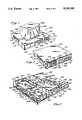
- FIG. 3is a perspective view of the compact system unit of FIG. 1 with the upper cover removed to illustrate the compact arrangement of system hardware within.
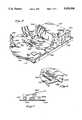
- FIG. 4is a perspective view, partially cut away, illustrating a floppy controller card connected directly to a mother board whereby the mother board and floppy controller card are co-planar.
- FIG. 5is an enlarged view illustrating a connector used for the co-planar arrangement of a floppy controller card and a mother board.
- FIG. 6is a sectional view, taken along the line 6-6 in FIG. 5.
- FIG. 7is a partial perspective view illustrating a bus expansion card mounted vertically to a mother board.
- FIG. 8is a cross sectional view of the bus expansion card of FIG. 7 mounted to a mother board.
- FIG. 9ais a detailed perspective view illustrating a rib extending from the inside of the cover of the computer system and designed to keep an expansion bus card from deflecting.
- FIG. 9bis a detailed view illustrating a rib extending from the inside of the base of the computer system and designed to support a mother board and prevent board deflection.
- FIG. 10is a partial perspective view illustrating a daughter board inverted over a mother board.
- FIG. 11is a perspective view illustrating an inverted daughter board.
- FIG. 12is a cross sectional view illustrating a daughter board inverted and mounted to a mother board.
- FIG. 13is an elevation view illustrating the rear of the system unit.
- FIG. 1illustrates generally a digital computer 100 with a new and improved compact system unit 102 as disclosed in the present invention.
- the digital computer 100comprises a video display monitor 104 having a flat base 106 and a CRT screen 108, the flat base 106 supporting the video monitor 104 on a generally flat support surface such as the compact system unit 102.
- the flat base 106is of sufficient area to enable the video monitor 104 to be stable when placed on the compact system unit 102.
- the compact system unit 102is housed within an enclosure 109.
- the enclosure 109comprises two sections 110 and 111, wherein section 110 constitutes a lower section and section 111 constitutes an upper, larger section. Both the sections 110 and 111 are engaged to form the compact enclosure 109.
- the compact system unit 102 encased within the enclosure 109further comprises an upper wall 112 and an opposing bottom wall 114.
- the flat base 106 of the video monitor 104is supported on the upper wall 112.
- the compact system unit 102further comprises identical opposing side walls 116 and 118, a front wall 120 and a rear wall 122.
- a diskette drive 124including a narrow opening 128 through which a diskette (not shown) may be inserted.
- a panel 136Located toward the right side of the front wall 120 is a panel 136, providing three indicator lights 138 oriented one below the other along a vertical axis, a key lock switch 140 and a reset button 142.
- the indicator lights 138indicate the machine speed (10 MHz or 6 Mhz) and hard disk activity.
- FIG. 2illustrates the rear wall 122 having a rear system unit panel 144.
- a power switch 145Located on the extreme upper left corner of the rear system unit panel 144 is a power switch 145 and adjacently aligned with the power switch 145 is a 3-pin power socket outlet 146. Directly below the 3-pin socket 146 is a power inlet connector 148 and adjacent to the 3-pin socket and directly below the power switch 145 is an input voltage select switch 150.
- a cooling fan frame 158covers a cooling fan 160 which is attached to the rear panel of the power supply 194 by screws 162, as best seen in FIG. 3.
- Located proximate the cooling fan 158, toward the lower end of the rear system unit panel 144are a video port 164 and a circular keyboard connection port 166.
- Proximate the keyboard connection port 166are located three horizontally aligned ports: a serial 1 port 168, a serial 2 port 170 and a parallel port 172.
- a serial 1 port 168Above the video port 164 and the keyboard connection port 166 is provided a large rectangular opening 174 used for expansion purposes.
- a relatively larger rectangular opening 176Horizontally aligned with the large rectangular opening 174 is a relatively larger rectangular opening 176; provided for I/O purposes.
- FIG. 3illustrates the system hardware components compactly integrated in a co-planar arrangement within the system unit 102 consistent with the preferred embodiment of the present invention.
- the system unit 102 as illustrated in FIG. 3comprises a hard disk 178 placed directly behind the panel 136 on the front wall 120.
- the hard disk 178is mounted within an individual housing 180 having a left wall 181, which serves as a partition as well as supports the upper wall 112.
- the system unit 102further comprises a floppy disk drive 182 which is mounted within an individual housing 186 having a left wall 188 and a right wall 190 which are parallel and horizontally aligned with the left wall 181 of the housing 180.
- the left wall 188 and the right wall 190likewise serve as supports for the upper wall 112.
- Each of the housings 180 and 186is mounted onto the lower section 110 by snapping into circular bosses.
- the system unit 102also comprises a power supply 194 which is mounted in the extreme right corner of the rear wall 122, behind the hard disk 178. Additionally, the system unit also comprises a mother board 195, placed adjacent to the power supply 194 and extending along the entire length of the system unit 102. Mounted directly behind the floppy disk drive 182 is a daughter board 196. The daughter board 196, in this case, is an EGA monitor controller board. The daughter board 196 is mounted directly to the mother board 195 in an inverted orientation. Mounted adjacent to the daughter board 196 are two brackets, a front bracket 197 and a rear bracket 198. These brackets 197,198 are directly mounted to the bottom wall 114 through the mother board 195.
- the front bracket 197includes a narrow slot 199 extending along most of the length of the bracket 197, for supporting the bus expansion card 201 in place.
- the rear bracket 198is S-shaped and has a front end 203 which includes two projections 200 (as best shown in FIG. 8) for guiding and supporting the other end of the bus expansion card 201.
- the bus expansion card 201has a front side 202 and a rear side 204.
- the front side of the bus expansion card 202has two horizontally extending parallel connectors 206 and 208 which are placed proximate each other and are vertically aligned.
- the connectors 206 and 208establish a direct electrical connection with two optional expansion boards 210 and 212 (shown in FIG. 3) which are placed in stack formation in planes parallel to the plane of the mother board 195 and directly above one another.
- the optional expansion boards 210 and 212are further vertically aligned with the mother board 195.
- a mounting boss 222projecting up from the bottom wall 114.
- two additional mounting bosses 224 and 226are located side-by-side.
- Each of the above-mentioned mounting bosses 222, 224, 226 and 228 and an identical set of bosses along the opposite side wall 118,have a threaded interior to accommodate screws which hold the upper case portion 111 to the lower portion 110.
- a holding bracket 230which has two pairs of slim projections 232 and 234, extending along the entire width of the holding bracket 230. These projections form grooves which mount the edge of the optional expansion boards 210 and 212.
- the mother board 195has a right edge 236. Adjacent the right edge 236, the upper surface of the mother board mounts a right angle wafer connector 238.
- a floppy drive connector 239connects directly to the right angle wafer connector 238, and is attached rigidly to a floppy controller card 240.
- the floppy controller card 240thus plugs directly to the right edge 236 of the mother board 195 without an intervening cable.
- the floppy controller card 240 and the mother board 195are co-planar to reduce the vertical profile of the system.
- a hard disk connector 242Positioned proximate to the right angle wafer connector 238 on the mother board 195 is a hard disk connector 242.
- a hard disk signal cable 244plugs into the hard disk connector 242.
- the expansion bus card 201slides between the projections 200 that protrude from the front end of the rear bracket 198 and the slot 199 extending vertically down the front bracket 197.
- the front bracket 197includes a base section 246 extending parallel to the mother board 195 and a vertical section 248 extending perpendicular to the base section 246.
- the vertical section 248 of the front bracket 196has a top end 252 which projects at a 45 degree angle from the vertical.
- the base section 246 of the front bracket 197further includes two apertures 254 and 256 for receiving screws 258 and 260 which securely mount the front bracket 196 through the mother board 195 to the bottom wall 114 of the system.
- the expansion bus card 201connects directly into two expansion connectors 262 and 264 placed end-to-end on the mother board 195.
- the two expansion connectors 262 and 264are centered along the same longitudinal axis as the front bracket 197 and the rear bracket 198.
- a frame bracket 266Adjacent to the rear bracket 198 and mounted to the extreme left end of the rear wall 122 is a frame bracket 266 having two horizontal openings 268 and 270 extending along its width which are oriented vertically one above the other to enable the optional boards 210 and 212 to be mounted.
- a left end 274 of the frame bracket 266has a flat extended portion 276 having an aperture 278 that is aligned with a similar aperture 280 in the rear wall 122. Through the aligned apertures 278 and 280 is received a screw 282 which mounts the frame bracket 266 to the rear wall 122.
- the parallel port 172Directly below the frame bracket 266 toward the extreme left corner of the rear wall 122.
- FIG. 7further illustrates the bottom wall 114 of the system unit 102 having latitudinal ribs 288 and lateral ribs 290 extending in orthogonal directions.
- the ribs 288 and 290support the various system components and prevent deflection.
- a rib 292(shown in phantom) extending laterally is located directly below the two expansion connectors 262 and 264 to provide support when pressure is applied to plug the bus expansion card 201 into the bus connectors 262 and 264.
- FIG. 8further illustrates the manner in which the bus expansion card 201 is securely mounted through the mother board 195 to the bottom wall 114.
- the bus expansion card 201is cradled within the slot 199 extending along the front bracket 197 and the projections 200 extending outward from the rear bracket 198.
- the bus expansion cardis electrically connected to the mother board 195 via the two adjacent bus connectors 262 and 264.
- FIGS. 9a and 9billustrate the ribs extending above and below the bus expansion cards, respectively.
- FIG. 9ashows the laterally extending rib 294 having two portions 296 that project downward from the upper wall 112 of the system enclosure, on either side of a small opening 298.
- the bus expansion card 201is mounted to the mother board 195 the two portions 296 of the rib 294 receive the bus expansion card 201 within the opening 298 and thereby provide rigid support to the bus expansion card 201.
- FIG. 9bshows the laterally extending rib 292 which extends upwardly from the bottom wall 114, having a projecting portion 300.
- the projecting portion 300is provided to support the mother board 195 and prevent the mother board from deflecting when pressure is applied to the bus expansion board 201 during the process of inserting the bus expansion card 201 into the bus expansion connectors 262 and 264.
- FIGS. 10 and 11illustrate the daughter board 196 mounted to the mother board 195.
- the daughter board 196includes an L-shaped mounting bracket 302 having a vertical section 304 and a horizontal section 306.
- the horizontal section 306 of the mounting bracket 302is attached to the daughter board 196 by screws 312 that pass through the daughter board 196.
- the vertical section 304is similarly attached to the rear wall 122 of the system unit 102.
- a connector 316that electrically connects directly to the mother board 195.
- the daughter board 196is further mounted to the mother board 195 by a standoff 318.
- FIG. 12shows a side view of the daughter board 196 mounted to the mother board 195 in an inverted orientation.
- a port connector 313 mounted on either the daughter board 196 or the mother board 195may exit the rear wall 122 through the same opening.
- FIG. 13illustrates the rear system unit panel 144 of the compact system unit 102 showing the video port 164, the serial 1 port 168, the serial 2 port 170 and parallel port 172 horizontally aligned along the same longitudinal axis.
- the keyboard connection port 166is offset from the longitudinal axis.
Landscapes
- Engineering & Computer Science (AREA)
- Theoretical Computer Science (AREA)
- General Engineering & Computer Science (AREA)
- Physics & Mathematics (AREA)
- General Physics & Mathematics (AREA)
- Power Engineering (AREA)
- Human Computer Interaction (AREA)
- Computer Hardware Design (AREA)
- Mounting Of Printed Circuit Boards And The Like (AREA)
Abstract
Description
Claims (17)
Priority Applications (1)
| Application Number | Priority Date | Filing Date | Title |
|---|---|---|---|
| US07/232,714US5038308A (en) | 1988-08-16 | 1988-08-16 | Compact system unit for personal computers |
Applications Claiming Priority (1)
| Application Number | Priority Date | Filing Date | Title |
|---|---|---|---|
| US07/232,714US5038308A (en) | 1988-08-16 | 1988-08-16 | Compact system unit for personal computers |
Publications (1)
| Publication Number | Publication Date |
|---|---|
| US5038308Atrue US5038308A (en) | 1991-08-06 |
Family
ID=22874244
Family Applications (1)
| Application Number | Title | Priority Date | Filing Date |
|---|---|---|---|
| US07/232,714Expired - LifetimeUS5038308A (en) | 1988-08-16 | 1988-08-16 | Compact system unit for personal computers |
Country Status (1)
| Country | Link |
|---|---|
| US (1) | US5038308A (en) |
Cited By (48)
| Publication number | Priority date | Publication date | Assignee | Title |
|---|---|---|---|---|
| US5242061A (en)* | 1992-09-30 | 1993-09-07 | Mitac International Corp. | Apparatus for positioning interface cards in a computer housing |
| EP0581139A1 (en)* | 1992-07-25 | 1994-02-02 | ICOS Gesellschaft für Industrielle Communications Systeme mbH | Circuit board arrangement for computer or the like |
| US5287460A (en)* | 1989-04-14 | 1994-02-15 | Digital Communications Associates, Inc. | Bus interface circuit for dual personal computer architecture peripheral adapter board |
| US5287247A (en)* | 1990-09-21 | 1994-02-15 | Lsi Logic Corporation | Computer system module assembly |
| US5311397A (en)* | 1992-08-06 | 1994-05-10 | Logistics Management Inc. | Computer with modules readily replaceable by unskilled personnel |
| US5400055A (en)* | 1993-12-06 | 1995-03-21 | Ma; Hsi K. | Expansible notebook computer |
| US5457602A (en)* | 1989-12-30 | 1995-10-10 | Hitachi, Ltd. | Desk-top information processing apparatus having a height greater than its front surface width, a first leg with a cut-out for cooling air, and a second leg with non-aligned ends |
| USD364145S (en) | 1994-06-08 | 1995-11-14 | Canon Computer Systems, Inc. | Slim profile computer housing |
| EP0684563A1 (en)* | 1994-05-25 | 1995-11-29 | Tandem Computers Incorporated | Flexible bus routing structure |
| EP0687983A1 (en)* | 1994-06-14 | 1995-12-20 | Tulip Computers International B.V. | Motherboard for a computer of the AT type, and a computer of the AT type comprising such motherboard |
| US5490038A (en)* | 1994-04-06 | 1996-02-06 | Dell Usa, L.P. | Adapter apparatus for use in connecting a printed circuit board to a computer chasis |
| US5496181A (en)* | 1993-05-14 | 1996-03-05 | International Business Machines Corporation | Serviceable data terminal structure |
| US5497495A (en)* | 1991-05-07 | 1996-03-05 | Fuji Electric Co., Ltd. | Computer electronic system having a cover for every module |
| US5510954A (en)* | 1994-05-20 | 1996-04-23 | Silent Systems, Inc. | Silent disk drive assembly |
| US5544006A (en)* | 1995-01-18 | 1996-08-06 | Dell Usa, L.P. | Computer chassis having flexible card guide for expansion card insertion and removal |
| US5552965A (en)* | 1993-04-02 | 1996-09-03 | Saia Ag | Control apparatus having a compact and accessible arrangement of printed circuit boards |
| US5564930A (en)* | 1994-11-14 | 1996-10-15 | Yu; Ben H. | Modular computer case |
| US5646820A (en)* | 1993-06-21 | 1997-07-08 | Kabushiki Kaisha Toshiba | Portable computer having a case which contains a speaker in a front wall and a keyboard in an upper wall |
| WO1997037293A1 (en)* | 1996-04-02 | 1997-10-09 | Fieldworks, Inc. | Modular field computer workstation |
| US5689400A (en)* | 1994-05-31 | 1997-11-18 | Kabushiki Kaisha Toshiba | Portable electronic apparatus including space-saving component mounting features |
| US5763985A (en)* | 1996-05-13 | 1998-06-09 | Asinovsky; Vladimir A. | Computer housing |
| US5785533A (en)* | 1993-11-15 | 1998-07-28 | Siemens Nixdorf Informationssysteme Aktiengesellschaft | Termination panel for control unit |
| US5796579A (en)* | 1994-05-31 | 1998-08-18 | Kabushiki Kaisha Toshiba | Portable electronic apparatus having expansion connector covered by pivotally mounted upper and lower covers having laterally extending guide portions |
| US5978873A (en)* | 1997-09-24 | 1999-11-02 | Intel Corporation | Computer system including right angle processor and add-on card connectors |
| US5983249A (en)* | 1992-07-15 | 1999-11-09 | Mitsubishi Denki Kabushiki Kaisha | Card driven electronic apparatus |
| US5995365A (en)* | 1997-08-04 | 1999-11-30 | Dell U.S.A. L.P. | Computer with hard disk drive carrier |
| US6246574B1 (en)* | 1996-10-22 | 2001-06-12 | OCé PRINTING SYSTEMS GMBH | Sub-assembly for an assembly system |
| US6386909B1 (en) | 1995-01-06 | 2002-05-14 | Fci Americas Technology, Inc. | Card connector |
| US6599134B1 (en)* | 2000-06-02 | 2003-07-29 | Frank Duarte | Transverse backplane |
| US20040070936A1 (en)* | 1999-10-26 | 2004-04-15 | Giovanni Coglitore | High density computer equipment storage system |
| US6738260B2 (en)* | 2002-03-25 | 2004-05-18 | American Megatrends, Inc. | Dual-card receiving device |
| US6754085B2 (en)* | 2001-09-28 | 2004-06-22 | Adc Broadband Access Systems, Inc. | Mounting circuit boards in housings |
| US6805560B1 (en)* | 2003-09-02 | 2004-10-19 | Intel Corporation | Apparatus interconnecting circuit board and mezzanine card or cards |
| US20040252464A1 (en)* | 2003-06-11 | 2004-12-16 | Hewlett-Packard Development Company, L.P. | Computer system |
| US20040252467A1 (en)* | 2003-06-11 | 2004-12-16 | Hewlett-Packard Development Company, L.P. | Multi-computer system |
| US6850408B1 (en)* | 1999-10-26 | 2005-02-01 | Rackable Systems, Inc. | High density computer equipment storage systems |
| US6884098B2 (en)* | 2001-03-27 | 2005-04-26 | Hewlett-Packard Development Company, L.P. | Compressed I/O connector layout with shared post |
| US20050168945A1 (en)* | 2003-12-29 | 2005-08-04 | Giovanni Coglitore | Computer rack cooling system with variable airflow impedance |
| US20050219812A1 (en)* | 2004-04-01 | 2005-10-06 | Strobel Larry A | Environmental control system for personal computers |
| US20050270298A1 (en)* | 2004-05-14 | 2005-12-08 | Mercury Computer Systems, Inc. | Daughter card approach to employing multiple graphics cards within a system |
| US20100046174A1 (en)* | 2008-08-20 | 2010-02-25 | Hong Fu Jin Precision Industry (Shenzhen) Co.,Ltd. | Printed circuit board fixing structure and electronic device with same |
| EP2289314A1 (en) | 2009-08-25 | 2011-03-02 | Aant Cornelis Huisman | Device for assembling a fishing equipment |
| US20120021624A1 (en)* | 2009-04-23 | 2012-01-26 | George Tuma | Adapter |
| US20160095245A1 (en)* | 2014-09-25 | 2016-03-31 | Wistron Corporation | Electronic device with quick releasing function for an interface card |
| US9426932B2 (en) | 2013-03-13 | 2016-08-23 | Silicon Graphics International Corp. | Server with heat pipe cooling |
| US9612920B2 (en) | 2013-03-15 | 2017-04-04 | Silicon Graphics International Corp. | Hierarchical system manager rollback |
| US10243287B1 (en)* | 2018-04-26 | 2019-03-26 | Quanta Computer Inc. | Riser card |
| US20240206066A1 (en)* | 2022-12-20 | 2024-06-20 | Qualcomm Incorporated | Hybrid circuit board device to support circuit reuse and method of manufacture |
Citations (5)
| Publication number | Priority date | Publication date | Assignee | Title |
|---|---|---|---|---|
| GB2143117A (en)* | 1983-07-15 | 1985-02-06 | Richard Douglas Mountford | Case for accommodating a micro computer |
| US4669053A (en)* | 1984-05-31 | 1987-05-26 | Zenith Electronics Corporation | Portable personal computer |
| US4725244A (en)* | 1987-07-02 | 1988-02-16 | Tektronix, Inc. | System for assembling an electronic work station |
| US4769764A (en)* | 1986-08-11 | 1988-09-06 | Isaac Levanon | Modular computer system with portable travel unit |
| US4862327A (en)* | 1987-02-26 | 1989-08-29 | International Business Machines Corporation | Adapter card mounting in a low profile microcomputer |
- 1988
- 1988-08-16USUS07/232,714patent/US5038308A/ennot_activeExpired - Lifetime
Patent Citations (5)
| Publication number | Priority date | Publication date | Assignee | Title |
|---|---|---|---|---|
| GB2143117A (en)* | 1983-07-15 | 1985-02-06 | Richard Douglas Mountford | Case for accommodating a micro computer |
| US4669053A (en)* | 1984-05-31 | 1987-05-26 | Zenith Electronics Corporation | Portable personal computer |
| US4769764A (en)* | 1986-08-11 | 1988-09-06 | Isaac Levanon | Modular computer system with portable travel unit |
| US4862327A (en)* | 1987-02-26 | 1989-08-29 | International Business Machines Corporation | Adapter card mounting in a low profile microcomputer |
| US4725244A (en)* | 1987-07-02 | 1988-02-16 | Tektronix, Inc. | System for assembling an electronic work station |
Non-Patent Citations (2)
| Title |
|---|
| "Industrial Personal Computer for Class C Industrial Environment", IBM Technical Disclosure Bulletin, vol. 28, No. 7, Dec. 1985, pp. 2785-2798. |
| Industrial Personal Computer for Class C Industrial Environment , IBM Technical Disclosure Bulletin, vol. 28, No. 7, Dec. 1985, pp. 2785 2798.* |
Cited By (67)
| Publication number | Priority date | Publication date | Assignee | Title |
|---|---|---|---|---|
| US5287460A (en)* | 1989-04-14 | 1994-02-15 | Digital Communications Associates, Inc. | Bus interface circuit for dual personal computer architecture peripheral adapter board |
| US5457602A (en)* | 1989-12-30 | 1995-10-10 | Hitachi, Ltd. | Desk-top information processing apparatus having a height greater than its front surface width, a first leg with a cut-out for cooling air, and a second leg with non-aligned ends |
| US5287247A (en)* | 1990-09-21 | 1994-02-15 | Lsi Logic Corporation | Computer system module assembly |
| US5432913A (en)* | 1990-09-21 | 1995-07-11 | Smits; Gerard D. | Computer system module |
| US5497495A (en)* | 1991-05-07 | 1996-03-05 | Fuji Electric Co., Ltd. | Computer electronic system having a cover for every module |
| US5983249A (en)* | 1992-07-15 | 1999-11-09 | Mitsubishi Denki Kabushiki Kaisha | Card driven electronic apparatus |
| EP0581139A1 (en)* | 1992-07-25 | 1994-02-02 | ICOS Gesellschaft für Industrielle Communications Systeme mbH | Circuit board arrangement for computer or the like |
| US5311397A (en)* | 1992-08-06 | 1994-05-10 | Logistics Management Inc. | Computer with modules readily replaceable by unskilled personnel |
| US5242061A (en)* | 1992-09-30 | 1993-09-07 | Mitac International Corp. | Apparatus for positioning interface cards in a computer housing |
| US5552965A (en)* | 1993-04-02 | 1996-09-03 | Saia Ag | Control apparatus having a compact and accessible arrangement of printed circuit boards |
| US5496181A (en)* | 1993-05-14 | 1996-03-05 | International Business Machines Corporation | Serviceable data terminal structure |
| US5663867A (en)* | 1993-06-21 | 1997-09-02 | Kabushiki Kaisha Toshiba | Portable electronic apparatus having a plurality of card storage portions for removably housing a memory card |
| US5646820A (en)* | 1993-06-21 | 1997-07-08 | Kabushiki Kaisha Toshiba | Portable computer having a case which contains a speaker in a front wall and a keyboard in an upper wall |
| US5785533A (en)* | 1993-11-15 | 1998-07-28 | Siemens Nixdorf Informationssysteme Aktiengesellschaft | Termination panel for control unit |
| US5400055A (en)* | 1993-12-06 | 1995-03-21 | Ma; Hsi K. | Expansible notebook computer |
| US5490038A (en)* | 1994-04-06 | 1996-02-06 | Dell Usa, L.P. | Adapter apparatus for use in connecting a printed circuit board to a computer chasis |
| US5510954A (en)* | 1994-05-20 | 1996-04-23 | Silent Systems, Inc. | Silent disk drive assembly |
| CN1086477C (en)* | 1994-05-20 | 2002-06-19 | 无噪音系统公司 | Silent air cooled computer |
| US5596483A (en)* | 1994-05-20 | 1997-01-21 | Silent Systems, Inc. | Silent air cooled computer having a hard disk drive with an acoustic shield and a heat sink arranged exterior to the drive |
| US5536176A (en)* | 1994-05-25 | 1996-07-16 | Tandem Computers Incorporated | Flexible bus routing structure |
| EP0684563A1 (en)* | 1994-05-25 | 1995-11-29 | Tandem Computers Incorporated | Flexible bus routing structure |
| US5808860A (en)* | 1994-05-31 | 1998-09-15 | Kabushiki Kaisha Toshiba | Portable electronic apparatus with detachably mounted keyboard |
| US5796579A (en)* | 1994-05-31 | 1998-08-18 | Kabushiki Kaisha Toshiba | Portable electronic apparatus having expansion connector covered by pivotally mounted upper and lower covers having laterally extending guide portions |
| US5764476A (en)* | 1994-05-31 | 1998-06-09 | Kabushiki Kaisha Toshiba | Portable electronic apparatus having a base a display and a microphone |
| US5689400A (en)* | 1994-05-31 | 1997-11-18 | Kabushiki Kaisha Toshiba | Portable electronic apparatus including space-saving component mounting features |
| USD364145S (en) | 1994-06-08 | 1995-11-14 | Canon Computer Systems, Inc. | Slim profile computer housing |
| US5594621A (en)* | 1994-06-14 | 1997-01-14 | Tulip Computers International B.V. | Motherboard for a computer of the AT type, and a computer of the AT type comprising such motherboard. |
| EP0687983A1 (en)* | 1994-06-14 | 1995-12-20 | Tulip Computers International B.V. | Motherboard for a computer of the AT type, and a computer of the AT type comprising such motherboard |
| US5564930A (en)* | 1994-11-14 | 1996-10-15 | Yu; Ben H. | Modular computer case |
| US6386909B1 (en) | 1995-01-06 | 2002-05-14 | Fci Americas Technology, Inc. | Card connector |
| US5544006A (en)* | 1995-01-18 | 1996-08-06 | Dell Usa, L.P. | Computer chassis having flexible card guide for expansion card insertion and removal |
| WO1997037293A1 (en)* | 1996-04-02 | 1997-10-09 | Fieldworks, Inc. | Modular field computer workstation |
| US5763985A (en)* | 1996-05-13 | 1998-06-09 | Asinovsky; Vladimir A. | Computer housing |
| US6246574B1 (en)* | 1996-10-22 | 2001-06-12 | OCé PRINTING SYSTEMS GMBH | Sub-assembly for an assembly system |
| US5995365A (en)* | 1997-08-04 | 1999-11-30 | Dell U.S.A. L.P. | Computer with hard disk drive carrier |
| US5978873A (en)* | 1997-09-24 | 1999-11-02 | Intel Corporation | Computer system including right angle processor and add-on card connectors |
| US20040070936A1 (en)* | 1999-10-26 | 2004-04-15 | Giovanni Coglitore | High density computer equipment storage system |
| US8582290B2 (en) | 1999-10-26 | 2013-11-12 | Silicon Graphics International Corp. | High density computer equipment storage system |
| US20070159790A1 (en)* | 1999-10-26 | 2007-07-12 | Giovanni Coglitore | High density computer equipment storage system |
| US6850408B1 (en)* | 1999-10-26 | 2005-02-01 | Rackable Systems, Inc. | High density computer equipment storage systems |
| US6599134B1 (en)* | 2000-06-02 | 2003-07-29 | Frank Duarte | Transverse backplane |
| US6884098B2 (en)* | 2001-03-27 | 2005-04-26 | Hewlett-Packard Development Company, L.P. | Compressed I/O connector layout with shared post |
| US6754085B2 (en)* | 2001-09-28 | 2004-06-22 | Adc Broadband Access Systems, Inc. | Mounting circuit boards in housings |
| US6738260B2 (en)* | 2002-03-25 | 2004-05-18 | American Megatrends, Inc. | Dual-card receiving device |
| US20040252467A1 (en)* | 2003-06-11 | 2004-12-16 | Hewlett-Packard Development Company, L.P. | Multi-computer system |
| US7136283B2 (en) | 2003-06-11 | 2006-11-14 | Hewlett-Packard Development Company, L.P. | Multi-computer system |
| US7236358B2 (en) | 2003-06-11 | 2007-06-26 | Hewlett-Packard Development Company, L.P. | Computer system |
| US20040252464A1 (en)* | 2003-06-11 | 2004-12-16 | Hewlett-Packard Development Company, L.P. | Computer system |
| US6805560B1 (en)* | 2003-09-02 | 2004-10-19 | Intel Corporation | Apparatus interconnecting circuit board and mezzanine card or cards |
| US20050186807A1 (en)* | 2003-09-02 | 2005-08-25 | Jacek Budny | Apparatus inteconnecting circuit board and mezzanine card or cards |
| US20050048805A1 (en)* | 2003-09-02 | 2005-03-03 | Jacek Budny | Apparatus interconnecting circuit board and mezzanine card or cards |
| US20050168945A1 (en)* | 2003-12-29 | 2005-08-04 | Giovanni Coglitore | Computer rack cooling system with variable airflow impedance |
| US7508663B2 (en) | 2003-12-29 | 2009-03-24 | Rackable Systems, Inc. | Computer rack cooling system with variable airflow impedance |
| US20050219812A1 (en)* | 2004-04-01 | 2005-10-06 | Strobel Larry A | Environmental control system for personal computers |
| US7236359B2 (en)* | 2004-04-01 | 2007-06-26 | Strobel Larry A | Environmental control system for personal computers |
| US20050270298A1 (en)* | 2004-05-14 | 2005-12-08 | Mercury Computer Systems, Inc. | Daughter card approach to employing multiple graphics cards within a system |
| US20100046174A1 (en)* | 2008-08-20 | 2010-02-25 | Hong Fu Jin Precision Industry (Shenzhen) Co.,Ltd. | Printed circuit board fixing structure and electronic device with same |
| US20120021624A1 (en)* | 2009-04-23 | 2012-01-26 | George Tuma | Adapter |
| US8585442B2 (en)* | 2009-04-23 | 2013-11-19 | Hewlett-Packard Development Company, L.P. | Expansion card adapter |
| EP2289314A1 (en) | 2009-08-25 | 2011-03-02 | Aant Cornelis Huisman | Device for assembling a fishing equipment |
| US9426932B2 (en) | 2013-03-13 | 2016-08-23 | Silicon Graphics International Corp. | Server with heat pipe cooling |
| US10048729B2 (en) | 2013-03-13 | 2018-08-14 | Hewlett Packard Enterprise Development Lp | Server with heat pipe cooling |
| US9612920B2 (en) | 2013-03-15 | 2017-04-04 | Silicon Graphics International Corp. | Hierarchical system manager rollback |
| US20160095245A1 (en)* | 2014-09-25 | 2016-03-31 | Wistron Corporation | Electronic device with quick releasing function for an interface card |
| US9468123B2 (en)* | 2014-09-25 | 2016-10-11 | Wistron Corporation | Electronic device with quick releasing function for an interface card |
| US10243287B1 (en)* | 2018-04-26 | 2019-03-26 | Quanta Computer Inc. | Riser card |
| US20240206066A1 (en)* | 2022-12-20 | 2024-06-20 | Qualcomm Incorporated | Hybrid circuit board device to support circuit reuse and method of manufacture |
Similar Documents
| Publication | Publication Date | Title |
|---|---|---|
| US5038308A (en) | Compact system unit for personal computers | |
| US5708563A (en) | Computer with modular removable card cage | |
| US5119497A (en) | Enclosure for computer control unit | |
| US4084250A (en) | Modular assembly for an electronic computer | |
| US6097593A (en) | Semi-mobile desktop personal computer | |
| US5297000A (en) | Packaged circuit-boards | |
| JP3234860B2 (en) | Computer system | |
| US5006959A (en) | Cooling of circuit boards | |
| US6049973A (en) | Method of assembling an integrated computer module | |
| KR940008852B1 (en) | Electrical assembly mounting brackets for computer system | |
| US8405970B2 (en) | Computer enclosure and storage device module thereof | |
| US6650535B1 (en) | Fanless power supply | |
| EP0132152B1 (en) | Modular computer system | |
| US5612852A (en) | Compact housing for a computer workstation | |
| US6222725B1 (en) | Apparatus for mounting parts and personal computer equipped with the same | |
| US20030062906A1 (en) | Instrument with housing having recess for connectors | |
| JPH0721760A (en) | Enclosure device of disk driving device and mounting method | |
| US20020006031A1 (en) | Portable electronic device with easy-to-assemble circuit board module | |
| US7106581B2 (en) | Modular logic board chassis for a desktop computer | |
| US5627728A (en) | Expansion box for notebook computers | |
| US5793616A (en) | Computer system with special circuit board arrangement | |
| JP2000513838A (en) | Personal computer housing | |
| JPH10111734A (en) | Computer having attachment device | |
| US6046913A (en) | Panel mounted power module with adaptor mounting bracket | |
| CN219437244U (en) | Double-layer circuit board |
Legal Events
| Date | Code | Title | Description |
|---|---|---|---|
| AS | Assignment | Owner name:AST RESEARCH, INC., 2121 ALTON, AVENUE, IRVINE, CA Free format text:ASSIGNMENT OF ASSIGNORS INTEREST.;ASSIGNORS:LE, BAO G.;NEMEC, FREDERICK J.;REEL/FRAME:004928/0473 Effective date:19880811 Owner name:AST RESEARCH, INC., A DE CORP., CALIFORNIA Free format text:ASSIGNMENT OF ASSIGNORS INTEREST;ASSIGNORS:LE, BAO G.;NEMEC, FREDERICK J.;REEL/FRAME:004928/0473 Effective date:19880811 | |
| STCF | Information on status: patent grant | Free format text:PATENTED CASE | |
| FEPP | Fee payment procedure | Free format text:PAYOR NUMBER ASSIGNED (ORIGINAL EVENT CODE: ASPN); ENTITY STATUS OF PATENT OWNER: LARGE ENTITY | |
| FPAY | Fee payment | Year of fee payment:4 | |
| AS | Assignment | Owner name:BANK OF AMERICA NATIONAL TRUST AND SAVINGS ASSOCIA Free format text:SECURITY INTEREST;ASSIGNOR:AST RESEARCH, INC., A DELAWARE CORPORATION;REEL/FRAME:007288/0234 Effective date:19941223 | |
| AS | Assignment | Owner name:AST RESEARCH, INC., CALIFORNIA Free format text:RELEASE BY SECURED PARTY;ASSIGNOR:BANK OF AMERICA NATIONAL TRUST AND SAVINGS ASSOCIATION;REEL/FRAME:007492/0165 Effective date:19950901 | |
| FPAY | Fee payment | Year of fee payment:8 | |
| AS | Assignment | Owner name:AST RESEARCH, INC., CALIFORNIA Free format text:SECURITY INTEREST;ASSIGNOR:AST COMPUTERS, LLC;REEL/FRAME:009703/0089 Effective date:19990108 | |
| AS | Assignment | Owner name:SAMSUNG ELECTRONICS AMERICA, INC., NEW JERSEY Free format text:ASSIGNMENT OF ASSIGNORS INTEREST;ASSIGNOR:ARI SERVICE, INC.;REEL/FRAME:012665/0878 Effective date:20020318 Owner name:ARI SERVICE, INC., CALIFORNIA Free format text:AGREEMENT OF MERGER AST RESEARCH, INC., WITH AND INTO ARI SERVICE, INC.;ASSIGNORS:AST RESEARCH, INC., A DELAWARE CORPORATION;ARI SERVICE, INC., A CALIFORNIA CORPORATION;REEL/FRAME:012691/0384 Effective date:20000330 | |
| AS | Assignment | Owner name:SAMSUNG ELECTRONICS CO., LTD., KOREA, REPUBLIC OF Free format text:ASSIGNMENT OF ASSIGNORS INTEREST;ASSIGNOR:SAMSUNG ELECTRONICS AMERICA, INC.;REEL/FRAME:012721/0141 Effective date:20020326 | |
| AS | Assignment | Owner name:AST COMPUTERS, LLC, CALIFORNIA Free format text:RELEASE OF SECURITY INTEREST;ASSIGNOR:ARI SERVICE, INC., AS SUCCESSOR IN INTEREST BY MERGER TO AST RESEARCH, INC.;REEL/FRAME:012852/0320 Effective date:20020503 | |
| FEPP | Fee payment procedure | Free format text:PAYER NUMBER DE-ASSIGNED (ORIGINAL EVENT CODE: RMPN); ENTITY STATUS OF PATENT OWNER: LARGE ENTITY Free format text:PAYOR NUMBER ASSIGNED (ORIGINAL EVENT CODE: ASPN); ENTITY STATUS OF PATENT OWNER: LARGE ENTITY | |
| FPAY | Fee payment | Year of fee payment:12 |