US5037518A - Apparatus and method for generating hydrogen and oxygen by electrolytic dissociation of water - Google Patents
Apparatus and method for generating hydrogen and oxygen by electrolytic dissociation of waterDownload PDFInfo
- Publication number
- US5037518A US5037518AUS07/405,633US40563389AUS5037518AUS 5037518 AUS5037518 AUS 5037518AUS 40563389 AUS40563389 AUS 40563389AUS 5037518 AUS5037518 AUS 5037518A
- Authority
- US
- United States
- Prior art keywords
- water
- hydrogen
- separator
- electrolytic cell
- anode
- Prior art date
- Legal status (The legal status is an assumption and is not a legal conclusion. Google has not performed a legal analysis and makes no representation as to the accuracy of the status listed.)
- Expired - Lifetime
Links
Images


Classifications
- C—CHEMISTRY; METALLURGY
- C25—ELECTROLYTIC OR ELECTROPHORETIC PROCESSES; APPARATUS THEREFOR
- C25B—ELECTROLYTIC OR ELECTROPHORETIC PROCESSES FOR THE PRODUCTION OF COMPOUNDS OR NON-METALS; APPARATUS THEREFOR
- C25B15/00—Operating or servicing cells
- C—CHEMISTRY; METALLURGY
- C25—ELECTROLYTIC OR ELECTROPHORETIC PROCESSES; APPARATUS THEREFOR
- C25B—ELECTROLYTIC OR ELECTROPHORETIC PROCESSES FOR THE PRODUCTION OF COMPOUNDS OR NON-METALS; APPARATUS THEREFOR
- C25B1/00—Electrolytic production of inorganic compounds or non-metals
- C25B1/01—Products
- C25B1/02—Hydrogen or oxygen
- C25B1/04—Hydrogen or oxygen by electrolysis of water
- C—CHEMISTRY; METALLURGY
- C25—ELECTROLYTIC OR ELECTROPHORETIC PROCESSES; APPARATUS THEREFOR
- C25B—ELECTROLYTIC OR ELECTROPHORETIC PROCESSES FOR THE PRODUCTION OF COMPOUNDS OR NON-METALS; APPARATUS THEREFOR
- C25B9/00—Cells or assemblies of cells; Constructional parts of cells; Assemblies of constructional parts, e.g. electrode-diaphragm assemblies; Process-related cell features
- C25B9/70—Assemblies comprising two or more cells
- C25B9/73—Assemblies comprising two or more cells of the filter-press type
- Y—GENERAL TAGGING OF NEW TECHNOLOGICAL DEVELOPMENTS; GENERAL TAGGING OF CROSS-SECTIONAL TECHNOLOGIES SPANNING OVER SEVERAL SECTIONS OF THE IPC; TECHNICAL SUBJECTS COVERED BY FORMER USPC CROSS-REFERENCE ART COLLECTIONS [XRACs] AND DIGESTS
- Y02—TECHNOLOGIES OR APPLICATIONS FOR MITIGATION OR ADAPTATION AGAINST CLIMATE CHANGE
- Y02E—REDUCTION OF GREENHOUSE GAS [GHG] EMISSIONS, RELATED TO ENERGY GENERATION, TRANSMISSION OR DISTRIBUTION
- Y02E60/00—Enabling technologies; Technologies with a potential or indirect contribution to GHG emissions mitigation
- Y02E60/30—Hydrogen technology
- Y02E60/36—Hydrogen production from non-carbon containing sources, e.g. by water electrolysis
Definitions
- the present inventionrelates to methods and apparatus for the generation of gases. More particularly, the present invention relates to methods and apparatus for the generation of hydrogen and oxygen by the electrolytic dissociation of water.
- a gassuch as oxygen, hydrogen or chlorine
- a gassuch as oxygen, hydrogen or chlorine
- electrolytic cellstake a variety of forms, but generally include a catalytic anode, a catalytic cathode and an adjacent electrolyte which is in electrical contact with both the anode and the cathode.
- a d-c voltageis applied across the catalytic electrodes to drive the reaction.
- the electrolyteis a solid polymeric ion-exchange membrane.
- Gas generators employing electrolytic cellsmay be used in many applications in place of compressed gas stored in cylinders. Moreover, electrolytic cells make possible the manufacture of inexpensive, compact devices for producing gas at the point of use.
- An example of an electrolytic cell gas generatoris described in Dempsey et al. U.S. Pat. No. 3,870,616, which describes a hydrogen generator having a main water tank supplying water to the anode of an electrolytic cell for dissociation. However, not all the water supplied to the anode is dissociated. In fact, the bulk of the water supplied to the anode is transported with the dissociated hydrogen ions across the ion-exchange membrane into the cathode chamber.
- the water contained in an electrolytic cell gas generatorcan become contaminated with impurities, such as metals, salts, acids, bases, or other electrolytes. Impurities such as these are contained in ordinary tap water. Once entered into the system, these impurities or contaminants are absorbed directly into the ion-exchange membrane, thereby "poisoning" the membrane and reducing the amount of uncontaminated surface area remaining to transport ions. As a result, the output of the cell is progressively reduced until the cell ceases to function entirely. This can be a gradual process or, if the amount of contamination is great enough, the membrane can be poisoned in a matter of minutes. Because these contaminants are invisible to an operator and electrolytic gas cell generators presently cannot detect if contaminated water is present, the ion-exchange membranes of these systems can be destroyed by the errant addition of tap water or other impure water into the generator.
- impuritiessuch as metals, salts, acids, bases, or other electrolytes.
- One particular object of the present inventionis to provide an electrolytic hydrogen and oxygen generator which produces hydrogen and oxygen at rates greater than those attainable in presently available electrolytic hydrogen generators.
- Another important object of the present inventionis to provide an electrolytic gas generator which is constructed to provide a longer productive lifetime for the ion-exchange membrane.
- a further important object of the present inventionis to provide a electrolytic cell gas generator which includes various safety features which protect the electrolytic cell from damage due to massive leaks, through the errant addition of impure water, or due to the absence of water from the supply system.
- a still further object of the present inventionis to provide a electrolytic gas generator having a solid-polymer-electrolyte electrolysis unit wherein the solid-polymer-electrolyte is protected from drying out.
- an electrolytic hydrogen and oxygen generatorcomprising an electrolytic cell having a cathode and an anode separated by an electrolyte; an electrical power supply connected to the electrolytic cell for applying a voltage across the cathode and anode; a water reservoir connected to the electrolytic cell for supplying water to the anode side of the cell; a hydrogen-water separator connected to the electrolytic cell for receiving hydrogen and water from the cathode side of the cell and separating the hydrogen from the water; and a water return line connecting the hydrogen-water separator to the water reservoir for returning water from the separator to the water reservoir so that the water is recycled to the anode side of said electrolytic cell.
- the water reservoirincludes a sensor for producing an electrical signal in response to a drop in the water level in the reservoir to a predetermined level or in response to a predetermined change in the electrical conductivity of the water in the reservoir, and control means responsive to the electrical signal from the sensor for interrupting the supply of electrical power to the electrolytic cell.
- the preferred embodimentalso includes a hydrogen output line for removing the hydrogen from the hydrogen-water separator, the hydrogen output line including a drying tube made of material which selectively adsorbs water vapor from gas flowing through the interior of the tube, and transfers the adsorbed water to the exterior of the tube.
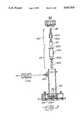
- FIG. 1is a schematic illustration of an electrolytic-cell hydrogen generator embodying the present invention
- FIG. 2is an exploded perspective of the electrolytic cell in the hydrogen generator of FIG. 1;
- FIG. 3is an exploded side elevation, partially in section, of the hydrogen-water separator in the generator of FIG. 1;
- FIG. 4is a block diagram of electrical circuits in the hydrogen generator
- FIG. 5is a simplified schematic diagram of electrical circuits for controlling current supplied to the hydrogen generator cell to obtain a selected level of hydrogen pressure
- FIG. 6is a simplified schematic diagram of electrical circuits which are used for detecting excessive water conductivity and lack of water in the hydrogen generator cell;
- FIG. 7is a simplified schematic diagram of electrical circuits which are used for detecting a failure of the hydrogen generator to achieve a selected pressure, for example, due to a massive leak in the generator;
- FIG. 8is a detailed schematic diagram of circuits for indicating a selected hydrogen pressure, sensing the actual hydrogen pressure, and shutting down the generator under certain abnormal conditions;
- FIG. 9is a detailed schematic diagram of the circuits for controlling the current supplied to the hydrogen generator cell to obtain a selected level of hydrogen pressure
- FIG. 10is a detailed schematic diagram of the circuits for detecting excessive water conductivity and lack of water in the hydrogen generator.
- FIG. 11is a detailed schematic diagram of the circuits for detecting the failure of the hydrogen generator to achieve a selected pressure.
- FIG. 1there is shown a gas generator which produces hydrogen and oxygen by the electrolysis of deionized, distilled water in an electrolytic cell C.
- Deionized, distilled wateris the only liquid contained in the apparatus, and must be replenished as it is consumed.
- Gas generators of this typeare intended for use in gas chromatography, flame ionization detectors, sulfur monitors, and other equipment requiring a source of pure hydrogen.
- the reservoir 1includes a sensor 3 for simultaneously sensing both the presence and the purity of water in the reservoir, as will be described in more detail below. If the sensor 3 detects either an inadequate water supply or impure water, it produces a signal which automatically interrupts the supply of electrical power to the cell C. This prevents damage to the electrolytic cell because supplying electrical power to the cell without an adequate supply of water, causes dissociation of the water contained within the solid-electrolyte membrane in the cell. This irreversibly "dries out” the membrane, thereby destroying the membrane and requiring replacement. Similarly, if the electrolytic cell were allowed to run with an impure water supply, the membrane would soon become contaminated with impurities. Again this would destroy, and require replacement of, the membrane.
- the reservoirs 1 and 2may be provided with a deionizing agent sealed in a porous envelope or bag 4 to alleviate the problem of possible membrane contamination from small quantities of impurities, including metal ions generated in the closed-loop water system.
- the reservoirs 1 and 2are preferably positioned above the electrolytic cell C so that water flows into the cell by gravity.
- the water levels in the reservoirsremain virtually the same since they are connected in parallel to a common water supply line 5 to the cell.
- the waterflows from the reservoirs 1 and 2 through respective lines 6 and 7 which converge at a Y connection 8 to the supply line 5.
- a check valve 9is provided in the supply line 5 downstream of the connection 8 to prevent the back flow of water into the lines 6 and 7.
- a drain line 5ais connected to the water supply line 5 via T connection 5b.
- This drain line 5acan be used not only to drain the system when desired, but also to connect the system to an auxiliary or larger water supply reservoir for applications where it is desired to have the unit operate continuously for periods longer than can be accommodated by the two reservoirs 1 and 2.
- the waterenters the water-tight housing of the electrolytic cell C through an inlet port 10.
- the inlet port 10leads to an internal conduit 11 which conducts the water to an anode chamber 12, located directly beneath an ion-exchange membrane 14 which serves as the solid electrolyte for the cell.
- a cathode chamber 13is formed directly above the membrane 14, and an electrical power supply (not shown in FIG. 1) is connected across the electrodes in the two chambers 12 and 13 so that the water is dissociated into ionic hydrogen and oxygen via electrolysis.
- the positively charged hydrogen ionsare transported across the ion-exchange membrane 14 into the cathode chamber 13 along with water molecules.
- the negatively charged oxygen ionsrecombine at the anode to form molecular oxygen within the anode chamber 12.
- the oxygen-enriched waterexits the anode chamber 12 through an internal conduit 15 leading to an outlet port 16 which communicates with a return conduit 17 to return the oxygen-enriched water to the reservoir 2.
- the return conduit 17includes an oxygen vent 18 which separates the oxygen gas from the water by venting the oxygen to the atmosphere.
- the reservoir 2preferably includes a similar vent in its cap 19 which vents any oxygen remaining in the water that is returned to this reservoir.
- the positively charged hydrogen ionscombine to form molecular hydrogen.
- These hydrogen moleculesalong with any water molecules transported across the membrane 14, flow out of the cathode chamber 13 through a conduit 20 into a hydrogen-water separator 21.
- the waterremains at the bottom of the separator 21 where a float valve 22 opens to discharge water into a conduit 23 whenever the water rises above the desired level. This insures that the upper region of the separator 21 remains open for the collection of hydrogen gas.
- hydrogendiffuses from the water into the upper region of the separator 21 for collection and further processing.
- the water conduit 23returns the water therein to the reservoir 1 via outlet port 24, return line 25 and a hydrogen vent 26 which separates entrained hydrogen gas from the water by venting the hydrogen to the atmosphere.
- the cap 27 of the reservoir 1preferably includes a similar vent which removes any remaining hydrogen from the water that is returned to this reservoir. Pressure for returning water from the separator 21 to the reservoir 1 is provided by the accumulated hydrogen in the separator, which forces water through the conduit 23 whenever the float valve 22 is open.
- the hydrogen gas that accumulates in the separator 21has a certain amount of water vapor entrained therein. This water vapor must be removed from the hydrogen because most uses for the hydrogen require pure hydrogen. Part of the water is removed from the hydrogen gas by passing the gas through a coalescing filter 28 in the upper region of the separator 21. As is well known, a coalescing filter forms a tortuous path which removes liquid droplets from a gas flowing therethrough.
- the hydrogenis further dried by passing it through a drying tube made of a material which selectively adsorbs water vapor from gas flowing through the interior of the tube, and transfers the adsorbed water to the exterior of the tube.
- a drying tubemade of a material which selectively adsorbs water vapor from gas flowing through the interior of the tube, and transfers the adsorbed water to the exterior of the tube.
- the hydrogenpasses upwardly through a conduit 30 to a drying coil 31 which removes a substantial portion of the water vapor from the hydrogen gas.
- the absorbed waterthen passes through the walls of the tubing and is evaporated from the outside surface of the tubing.
- suitable drying coilsare described in more detail in U.S. Pat. Nos. 3,735,558 and 4,705,543.
- Other drying devicessuch as a water trap for example, could be used in place of the drying tube.
- the hydrogen gaspasses into a desiccator chamber 33 filled with a desiccant such as silica gel or a molecular sieve, either of which can be regenerated from time to time rather than being replaced.
- a desiccantsuch as silica gel or a molecular sieve, either of which can be regenerated from time to time rather than being replaced.
- the partial drying of the hydrogen before it reaches the desiccator chamber 33extends the intervals at which the desiccant must be regenerated.
- the gasflows downwardly through the desiccant and exits at the bottom of the chamber 33 through a tube 34.
- the release of hydrogen gas from the unitis controlled by a shutoff valve 35 which connects the tube 34 to a hydrogen output port 36.
- a pressure gauge 37monitors the hydrogen pressure in the conduit 34 and is mounted on the front panel of the generator to display the pressure reading to the user.
- a pressure transducer 38also monitors the hydrogen pressure in the tube 34 and produces a corresponding electrical signal which is used to control the electrical power supplied to the electrolytic cell, as will be described in more detail below.
- FIG. 2A preferred embodiment of the electrolytic cell of the present invention is shown in FIG. 2.
- This cellhas a watertight housing 100 which clamps a solid polymeric ion-exchange membrane electrolyte 107 between a catalytic cathode 102 and a catalytic anode 103.
- These electrodes 102 and 103preferably have a thickness of at least about 0.020 inch each. Electrical power is supplied to the cathode 102 through two attachment points 102a and 102b at opposite ends thereof, and the anode 103 receives electrical power through two similar attachment points 103a and 103b.
- the heat generated by resistanceis directly related to the distance the current must travel through the resistor.
- the electrodes in electrolytic cellsact as resistors, and thus, heat is generated as a current is passed through them.
- the heat generated in the electrodes of the present inventionis substantially reduced by providing two electrical inputs for each electrode.
- Gaskets 106, 109 and 110are provided to insure a water-tight construction for the electrolytic cell.
- a gasket 105is provided between the anode 103 and the base of the housing 100 to electrically insulate the anode 103 from the base of the housing 100. This gasket 105 also has sufficient thermal conductivity to ensure good heat transfer from the electrodes into the housing 100, which serves as a heat sink.
- the housing 100in turn is fastened to a metal chassis which also becomes part of the heat sink.
- the two gaskets 106 and 109are preferably laminates having a catalytic screen 101 disposed between two non-conductive annular gaskets.
- the screenis in electrical contact with the adjacent electrode and functions as a part of that electrode.
- a pressure disc 108is disposed between the cathode 102 and the uppermost gasket 110 so that when the two housing sections are drawn together, the disc 108 exerts pressure on the screens.
- Waterenters the cell housing 100 through a tee connection 111 connected to the housing by a stem 112, with the other end of the tee leading to a drain port. Water and oxygen are removed from the housing via an outlet 113, and water and hydrogen are removed from the separator 21 via an outlet 114 in the housing 100.
- electrolytic celli.e., one pair of electrodes and one ion-exchange membrane
- two or more cellsmay be stacked on top of each other in a single housing in order to increase the hydrogen-producing capacity of the unit.
- FIG. 3illustrates a preferred embodiment of the hydrogen-water separator 21.
- the separatoris constructed as an elongated, cylindrical vessel attached to the electrolytic cell housing and communicating with the cathode chamber of the electrolytic cell through the inlet port 20. Hydrogen-enriched water enters the separator through the inlet port 20, and the water level gradually rises around a hollow stem 201 fitted into the top of the housing 100.
- the float valve 22cooperates with the stem 201 and is constructed from a tube 202 attached to a base 203 which in turn is attached to a hollow float valve body 204 sealed by a top 205.
- the tube 202telescopes over the stem 201 having a central bore 206 extending along its axis.
- the tube 202has two slots at its upper end to facilitate the flow of water between the main vessel of the separator 21 and the stem 201.
- the float assembly valve 22lifts off the stem 201, thereby opening the top of the stem 201. Hydrogen-enriched water flows through the stem to a conduit within the top of the housing 100 and then on to the main reservoir 1, thereby lowering the water level in the separator 21. When the water level in the separator is sufficiently low, the float valve 22 seats on top of the stem 201, thereby closing the water return line to the reservoir 1.
- a ball valve 207 at the top of the separator chamberensures that water never exits the separator 21 into the hydrogen conduit 30. If the water level should ever rise to the position of the ball valve 207, a ball 208 rises into a socket 209, sealing the outlet tube 30.
- the ball valve 207protects the rest of the unit from contamination by liquid water, and also protects any sensitive equipment the operator may have connected to the hydrogen outlet port.
- the hydrogen-water separatoralso includes a pressure relief valve 210 connected to a port 211 in the side wall of the main vessel of the separator 21.
- the relief valve 210will open, relieving the pressure. Accordingly, this valve prevents any accidental increase in pressure in the separator over acceptable limits which could damage the unit, any equipment connected to the unit, or the operator.
- the relief valve 210is particularly important in view of the fact that the ball valve 207 can close the only other gas exit from the separator 21.
- the ion-exchange membrane utilized in electrolytic cell gas generatorsis very delicate. For example, a sudden release of pressure in the separator can delaminate the membrane and render it inoperable.
- the float ball valve 207 included in the hydrogen gas collection chamberwill prevent such a sudden loss of gas pressure in the unit. For example, if the outlet valve 35 were to be open to the outside atmosphere without resistance, hydrogen would rush out, rapidly reducing the pressure in the system. However, in the event of such an occurrence, the rapid flow of hydrogen past the ball 208 will lift the ball into the socket 209, sealing the outlet tube 30. This will prevent any damage to the ion-exchange membrane.
- FIG. 4there is shown a block diagram of the preferred electrical circuits in the hydrogen generator.
- the pressure of the hydrogen gasis measured with the pressure transducer 38, and the hydrogen generator cell C is supplied with an amount of electrical current that is regulated in response to the difference between the measured pressure and the desired pressure.
- the desired pressureis indicated by the reference voltage from the pressure adjust potentiometer 502, and a differential amplifier 503 compares the reference voltage to a pressure-indicating voltage from the pressure transducer 38 to provide a control signal for regulating the electrical current to the cell.
- the hydrogen flow rate in the hydrogen output linecould be used as the controlling parameter. This would be desirable for certain applications where a controlled flow rate is more important than a controlled pressure.
- the pressure transducer 38would be replaced with a flow rate sensor, such as by sensing differential pressures in the hydrogen output line.
- a pulse width modulator 504is responsive to the control signal from the differential amplifier 503 and provides variable-width gate pulses to the SCR circuits 505.
- the cell currentis sensed by a threshold comparator 506 which provides a signal to inhibit the pulse width modulator 504 when a predetermined maximum cell current is reached.
- the current to the hydrogen-generating cell Cis shut off entirely when certain conditions occur.
- the sensing of these conditionstriggers a one-shot 507 that is reset only upon cycling a power switch "off” and then "on". In the usual case appropriate maintenance or servicing would be performed when the power switch is off before it is turned back on.
- the one-shotshuts off the current to the hydrogen cell by driving the reference voltage from the potentiometer 502 to an extreme minimum value.
- the one-shot 507could directly inhibit the SCR circuits 505.
- a cell voltage threshold detector 508supplies a shut-down signal to the one-shot 507.
- the solid electrolyteshould always be immersed in water. Also, to guarantee that pure hydrogen is generated and to avoid contamination of the solid electrolyte, the water must be deionized and should have a resistivity of at least a certain minimum value such as 100,000 ohm/cm. These conditions are insured by a water quality and level detector 509 that provides a shut-down signal to the one-shot 507 in the absence of a minimum level of high quality water in the hydrogen generator cell C.
- a mass leak detector 510provides a shutdown signal to the one-shot 507 when the hydrogen pressure fails to increase at a predetermined minimum rate if it has not already reached the desired pressure.
- the pulse width modulator 504includes a resistor 511, a capacitor 512, directional diodes 513 and 514, and a level detector 515. Associated with the pulse width modulator 504 is a transistor 516 and a resistor 517 which are responsive to a source 518 of pulses at the zero crossings in the 60-Hz. or 50-Hz. voltage from the power lines.
- the transistor 516applies the pulses to the reference voltage from the potentiometer 502 and the pulses are transferred through the differential amplifier 503 and cause the output of the differential amplifier to go negative and be clamped by diode 513 so that the capacitor 512 is discharged to approximately ground potential through the diode 514 during each zero crossing.
- the pulsesare relatively narrow and therefore during the absence of the pulses the capacitor 512 is charged through resistor 511 up to a value responsive to the difference or between the desired pressure and the measured pressure.
- the voltage across the capacitor 512is applied to a level detector 515 which has a predetermined threshold above ground potential. Pulses from the level detector 515 are applied to the gates of the SCRs 519 and 520 which are wired to the hydrogen generating cell C and a center-tapped secondary of a power transformer 521 in a full-wave rectifier circuit. Since the gating pulses to the SCRs occur at a variable time delay from the zero crossings in the power line voltage, the conduction angle of the SCRs and the current through the cell are adjusted in response to the difference between the desired pressure and the measured pressure.
- FIG. 6there is shown a simplified schematic diagram of the water quality and level detector circuits 509 which interrupt the supply of electrical power to the electrolytic cell whenever (1) the water level in the reservoir becomes too low, or (2) impure water is present in the reservoir, e.g., as a result of the addition of tap water rather the deionized distilled water.
- These circuitsinclude the water probe 3 having a pair of spaced electrodes disposed in the water reservoir 1, an oscillator 531 for energizing the electrodes, a first differential amplifier 532 and a second differential amplifier 533.
- the first differential amplifier 532senses the voltage across a resistor 534 which is in series with the water probe 3.
- the second differential amplifier 533senses the voltage across the water probe 3.
- the value of the resistor 534 and the respective gains of the differential amplifiers 532 and 533are selected so that both of the differential amplifiers provide respective alternating-current output signals that are substantial only when the resistance between the electrodes of the water probe falls within a predetermined range. If the level of the water in the water reservoir 1 falls below the tips of the electrodes in the water probe 3, then an insubstantial amount of current will flow through the resistor 534. In this case only the second differential amplifier 533 will generate a substantial output signal. Conversely, when the resistivity of the water falls below the minimum resistivity, then only the first differential amplifier 532 will generate a substantial output signal.
- the outputs of the two differential amplifiers 532, 533are wired in a bridge circuit including directional diodes 535, 536, 537, and 538; resistors 539, 540, 541, and 542; and transistors 543 and 544.
- the diode bridgeis balanced and neither of the transistors 543 and 544 is activated.
- the signal from the first differential amplifier 532cause the diode 535 and the transistor 543 to conduct, thereby signaling that the water should be changed.
- the signal from the second differential amplifier 533causes the diode 538 and the transistor 544 to conduct, thereby signalling that the water level is low.
- sensorsother than electrodes may be used to sense the "charge water” or "low water” conditions.
- an optical sensor or a float switchcould be used to sense the water level.
- FIG. 7there is shown a simplified schematic diagram of the massive leak detector 510.
- the massive leak detectoris operative only when the hydrogen pressure has failed to reach the desired pressure. This condition is detected by a comparator 550 that compares the reference voltage from the pressure adjusting potentiometer 502 to the pressure indicating signal from the pressure transducer 38.
- the differential amplifier 550is matched with the differential amplifier 503 of FIG. 5 so that the output signal of the amplifier 550 will be at a positive voltage only when the hydrogen generating cell is energized and the measured pressure has failed to reach the desired pressure. Under these conditions, the hydrogen generating cell should generate a sufficient amount of hydrogen gas to increase the pressure at a substantial rate until the measured pressure reaches the desired pressure.
- the massive leak detector 510includes a capacitor 551 which is periodically connected by a controlled switch 552 to the output voltage of the pressure transducer 38.
- the switch 552is pulsed closed at the prescribed intervals.
- the increase in the pressure-indicating voltage over the prescribed intervalappears as a voltage pulse across a resistor 553 in series with the capacitor 551. If the hydrogen generator is operating properly, then the voltage pulse turns on a transistor 555.
- a massive leakis detected when the transistor 555 fails to be turned on within a prescribed time interval whenever the measured pressure is below the desired pressure.
- the output of the comparator 550charges a capacitor 557 through a resistor 556, and the capacitor 557 is connected to the collector of the transistor 555 to discharge the capacitor when the transistor turns on.
- the voltage across the capacitor 557is fed to a shutdown detector that has a predetermined threshold voltage to which the capacitor 557 is charged by the comparator 550 unless the transistor 555 turns on.
- the shutdown detector 558will assert a signal indicating the presence of the massive leak and fire the one shot 507 (FIG. 4) permanently.
- FIG. 8there is shown a detailed schematic diagram of the preferred circuits associated with the pressure-adjusting potentiometer 502, the one-shot 507 and the pressure transducer 38.
- the electronic circuitsare powered by a secondary 560 of the power transformer 521 that is separate from the secondary 561 that supplies current to the hydrogen-generating cell C.
- the primary of the power transformer 521is connected to the power lines through a switch 562.
- the secondary coil 560has a grounded center tap and is connected to a bridge rectifier 563.
- the positive and negative outputs of the bridge rectifier 563are shunted to ground through respective electrolytic filter capacitors 564 and 565.
- the positive and negative output voltages of the bridge rectifier 563are regulated by respective positive and negative voltage regulators 566 and 567.
- the outputs +VCC and -VCCare shunted to ground by respective electrolytic capacitors 568 and 569.
- the output of the positive voltage regulator 566is connected through a voltage-dropping resistor 570 to a zener diode 571.
- the voltage across the zener diode 571is buffered by an amplifier 572 having its gain set by resistors 573 and 574.
- the pressure transducer 38has a balanced resistive strain gage bridge 575, and the difference voltage across the bridge is amplified by a pair of differential amplifiers 576 and 577 that are wired so as not to amplify common mode signals.
- the amplifierswork in connection with feedback resistors 578, 579, 580, and 581.
- the pressure-adjusting potentiometer 502is connected through resistors 517 and 583 to the reference voltage from the amplifier 572.
- the voltage referenceis removed from the pressure-adjusting potentiometer 502 when the one-shot 507 is triggered by a shut-down signal.
- the bistable element of the one-shotis an SCR 584 having a snubbing capacitor 585 and resistor 586.
- the cathode of the SCRis biased by resistors 587 and 588 to a negative voltage between ground and -VCC.
- a transistor 589receives the shut-down signal and is wired as an emitter follower to drive the gate of the SCR through a current-limiting resistor 590 and a shunt resistor 591.
- the voltage across the pressure-adjusting potentiometer 502is also interrupted periodically by pulses at the zero crossings in the power line voltage.
- the pulse generator circuits 518include a transistor 516 having its emitter held at a negative voltage by a resistor 593 connected to ground and a resistor 594 connected to -VCC. To turn the transistor 516 on and off at the zero crossings of the power line voltage, the transistor is normally turned off by a negative voltage from either one of two directional diodes 595 and 596 connected to the AC inputs of the bridge rectifier 563.
- the base of the transistor 516is connected to these diodes 595 and 596 through a resistor 597, and is also connected to the positive supply +VCC through a resistor 598, and the values of the resistors 597 and 598 are selected so that the transistor 516 is turned on for a short time during each zero crossing.
- the base and the emitter of the transistor 516are shunted by a directional diode 599 to prevent the base of the transistor from being reversed biased.
- FIG. 9there is shown a detailed schematic diagram of the differential amplifier 503, the pulse width modulator 504, the SCR drive and power control circuits 505, the maximum cell current feedback circuits 506, and the cell over voltage detector 508.
- the pressure-indicating signal from the pressure transducer(38 in FIG. 8) is applied to the differential amplifier 503 through a low-pass filter including series resistors 610 and 611, and a shunt capacitor 612.
- the gain of the differential amplifier 503is set by a feedback resistor 613.
- the level detector 515includes a differential amplifier 614 having a threshold set by a voltage divider including resistors 615 and 616.
- the output of the differential amplifier 614is connected to a capacitor 617 which in turn is connected to a positive feedback resistor 618.
- the capacitor 617is also shunted to ground by a clamping diode 619 and a resistor 620 so that positive pulses are generated across the resistor 620.
- the pulses across the resistor 620are applied to the base of a transistor 621 wired in an emitter-follower configuration.
- the emitter of the transistor 621is connected to respective series resistors 622, 623 and shunt resistors 624 and 625 which are in turn connected to the gates of the SCRs.
- the collector of the transistor 621is fed by current through a light-emitting diode 626 having its anode connected to +VCC.
- a capacitor 628supplies current for pulses to the SCR gates, and the capacitor 628 and a resistor 627 average these high current pulses to approximately d-c. for the light-emitting diode 626.
- the currentis sensed by a series resistor 630 having a relatively low resistance.
- the current through this resistancecreates a relatively small negative voltage which is low-pass filtered by a resistor 631 and an electrolytic capacitor 632.
- the maximum cell current detector 506further includes a differential amplifier 633 which compares the voltage across the capacitor 632 to a reference voltage provided by a voltage divider including a resistor 634 and a variable resistor 635.
- the gain of the amplifier 633is set by a series resistor 636 and a negative feedback resistor 637.
- the output of the amplifier 633is fed back to the threshold-detecting amplifier 614 through a directional diode 638.
- the diode 638will be reverse biased, and the amplifier 633 will have a negligible effect on the threshold-detecting amplifier 614.
- the over voltage detector 508shuts off the hydrogen-generating cell entirely when the cell voltage exceeds a certain maximum limit.
- the cell voltageis low-pass filtered by a resistor 640 and an electrolytic capacitor 641.
- the cell over voltage detector 508further includes a differential amplifier 642 having a gain set by a series resistor 643 and a negative feedback resistor 644.
- the desired voltage thresholdis provided by a resistor voltage divider including resistors 645 and 646.
- the amplifier 642is connected to the transistor 589 of the one-shot circuit 507 of FIG. 8, through a directional diode 647 and a resistor 648. Therefore, when the cell voltage exceeds the threshold value, the amplifier 642 forward biases the diode 647, and current flows through the diode to turn on the transistor 589 in FIG. 8 to trigger the one-shot (507 in FIG. 8) and shut off the current to the hydrogen-generating cell C.
- the oscillator 531includes an integrated circuit 650 that works in connection with capacitors 651, 652, resistors 653, 654 and directional diodes 655 and 656.
- the signal from the integrated circuit 650is coupled through a tantalum capacitor 657 to the current-sensing resistor 534. Due to the rather high resistance being sensed, the signal across the water probe 3 is buffered by a follower amplifier 658 before being applied to the amplifiers 532 and 533.
- the first amplifier 532works in connection with resistors 659, 660, 661 and 662, and the second amplifier 533 works in connection with a coupling capacitor 663 and resistors 664, 665, and 666.
- the outputs of the amplifiers 532, 533are connected to the diode bridge including the diodes 535 to 538 and the resistors 539 to 542.
- the midpoints of the diode bridqeare connected to the transistors 543 and 544. To reject noise, the midpoints of the bridge are shunted to ground by resistors 667, 667a and capacitors 668 and 669.
- the collectors of the transistors 543 and 544are connected to respective light-emitting diodes 670 and 671 which share a common current-limiting resistor 672.
- the voltage across the current-limiting resistor 672is coupled through a capacitor 673 to the voltage reference in the cell over voltage detector 508 of FIG. 9. This is the most convenient method of connecting the water quality detector to the one-shot 507 of FIG. 8.
- the pulse generator 554includes an integrated circuit 680 working in connection with capacitors 681, 682 and resistors 683 and 684.
- the controlled switch 552is preferably an optical coupler.
- the light-emitting diode of the optical coupler 552is connected to the output of the integrated circuit 680 through a current-limiting resistor 685.
- a directional diode 686shunts the controlled switch 552 to ensure that the phototransistor of the switch is not reverse biased.
- the differential amplifier 550works in connection with resistors 687, 688 and 689.
- the amplifier 550charges the capacitor 557 through a directional diode 690 and the resistor 556.
- the capacitor 557discharges through the resistor 556 and a shunt resistor 691.
- the capacitor 551should have low leakage and is preferably a polycarbonate capacitor.
- an amplifier 692between the resistor 553 and the transistor 555.
- the amplifier 692works in connection with a capacitor 693 and resistors 694, 695 and 696.
- the output of the amplifier 692is coupled to the transistor 555 through a network including directional diodes 697 and 698, a capacitor 699 and resistors 700 and 701.
- wateris recycled from the hydrogen-water separator to the anode side of the electrolytic cell by returning water from the separator to the water reservoir.
- This featurepermits water to be supplied continuously from the reservoir to the anode chamber, without the need to periodically reverse the movement of water molecules through the solid electrolyte and the attendant danger of drying out and irreversibly damaging the electrolyte.
Landscapes
- Chemical & Material Sciences (AREA)
- Engineering & Computer Science (AREA)
- Chemical Kinetics & Catalysis (AREA)
- Electrochemistry (AREA)
- Materials Engineering (AREA)
- Metallurgy (AREA)
- Organic Chemistry (AREA)
- Inorganic Chemistry (AREA)
- Electrolytic Production Of Non-Metals, Compounds, Apparatuses Therefor (AREA)
Abstract
Description
Claims (8)
Priority Applications (2)
| Application Number | Priority Date | Filing Date | Title |
|---|---|---|---|
| US07/405,633US5037518A (en) | 1989-09-08 | 1989-09-08 | Apparatus and method for generating hydrogen and oxygen by electrolytic dissociation of water |
| EP90117191AEP0417647A1 (en) | 1989-09-08 | 1990-09-06 | Apparatus and method for generating hydrogen and oxygen by electrolytic dissociation of water |
Applications Claiming Priority (1)
| Application Number | Priority Date | Filing Date | Title |
|---|---|---|---|
| US07/405,633US5037518A (en) | 1989-09-08 | 1989-09-08 | Apparatus and method for generating hydrogen and oxygen by electrolytic dissociation of water |
Publications (1)
| Publication Number | Publication Date |
|---|---|
| US5037518Atrue US5037518A (en) | 1991-08-06 |
Family
ID=23604523
Family Applications (1)
| Application Number | Title | Priority Date | Filing Date |
|---|---|---|---|
| US07/405,633Expired - LifetimeUS5037518A (en) | 1989-09-08 | 1989-09-08 | Apparatus and method for generating hydrogen and oxygen by electrolytic dissociation of water |
Country Status (2)
| Country | Link |
|---|---|
| US (1) | US5037518A (en) |
| EP (1) | EP0417647A1 (en) |
Cited By (81)
| Publication number | Priority date | Publication date | Assignee | Title |
|---|---|---|---|---|
| US5110436A (en)* | 1991-02-01 | 1992-05-05 | The United States Of America As Represented By The Adminstrator Of The National Aeronautics And Space Administration | Water electrolysis |
| US5231954A (en)* | 1992-08-05 | 1993-08-03 | J. C. Conner | Hydrogen/oxygen fuel cell |
| US5318684A (en)* | 1992-09-17 | 1994-06-07 | Charles Cameron | Systems for the decomposition of water |
| US5399251A (en)* | 1990-04-26 | 1995-03-21 | Nakamats; Yoshiro | System for generating hydrogen and oxygen |
| US5484512A (en)* | 1992-01-08 | 1996-01-16 | Shinko Pantec Co., Ltd. | Methods and apparatuses for producing high purity oxygen and hydrogen |
| US5549445A (en)* | 1987-06-26 | 1996-08-27 | Schremp; Edward J. | Macro-engineering process and system for all-weather at-sea wind-energy extraction |
| US5688384A (en)* | 1994-09-14 | 1997-11-18 | British Nuclear Fuels Plc | Fluorine cell |
| US5690797A (en)* | 1995-01-18 | 1997-11-25 | Mitsubishi Corporation | Hydrogen and oxygen gas generating system |
| US5711865A (en)* | 1993-03-15 | 1998-01-27 | Rhyddings Pty Ltd | Electrolytic gas producer method and apparatus |
| US5728274A (en)* | 1996-08-13 | 1998-03-17 | Hoshizaki Denki Kabushiki Kaisha | Production system of electrolyzed water |
| US5733422A (en)* | 1997-02-28 | 1998-03-31 | Lin; I-Chuan | High-pressure gas producing electrolysis tank |
| US5741711A (en)* | 1995-09-13 | 1998-04-21 | Aviv Amirav | Flame-based method and apparatus for analyzing a sample |
| US5742050A (en)* | 1996-09-30 | 1998-04-21 | Aviv Amirav | Method and apparatus for sample introduction into a mass spectrometer for improving a sample analysis |
| DE19653034A1 (en)* | 1996-12-19 | 1998-07-02 | Dirk Schulze | Electrochemical cell for producing oxygen or ozone from water |
| WO1998042893A1 (en)* | 1997-03-25 | 1998-10-01 | Whatman Inc. | Direct current hydrogen generator, system and method |
| US5910773A (en)* | 1998-08-18 | 1999-06-08 | Brownlee; David W. | Oxygen supply system for wheeled vehicles |
| US5993618A (en)* | 1996-12-19 | 1999-11-30 | Dirk Schulze, Wolfgang Beyer Bonn | Device for generating oxygen or a mixture of ozone and oxygen |
| US6034606A (en)* | 1998-08-18 | 2000-03-07 | Brownlee; David W. | Oxygen enrichment system for wheeled vehicles cross-reference to related applications |
| US6033549A (en)* | 1996-11-06 | 2000-03-07 | Deutsche Forschungsanstalt Fuer Luft- Und Raumfahrt E.V. | Method of electrolysis |
| US6096178A (en)* | 1998-08-24 | 2000-08-01 | Aviv Amirav | Electrolyzer device for the operation of flame ionization detectors |
| US6191694B1 (en) | 1998-08-18 | 2001-02-20 | David W. Brownlee | Oxygen enrichment system for vehicles |
| US6299744B1 (en)* | 1997-09-10 | 2001-10-09 | California Institute Of Technology | Hydrogen generation by electrolysis of aqueous organic solutions |
| US6303009B1 (en)* | 1999-11-15 | 2001-10-16 | Peter R. Bossard | Hydrogen generator with feedback control |
| US20020020623A1 (en)* | 2000-07-20 | 2002-02-21 | Speranza A. John | Electrochemical cell system output control method and apparatus |
| US6380859B1 (en) | 1998-08-18 | 2002-04-30 | David W. Brownlee | Hyperbaric oxygen enrichment system for vehicles |
| US20020179433A1 (en)* | 2001-05-30 | 2002-12-05 | Dardik Irving I. | Pulsed electrolytic cell |
| US20030077491A1 (en)* | 2001-10-24 | 2003-04-24 | Lillis Mark A. | Weight sensing system, method for use thereof, and electrochemical system for use therewith |
| US20030180587A1 (en)* | 2000-09-01 | 2003-09-25 | Jones Peter Brian | Portable hydrogen source |
| US20030201187A1 (en)* | 2002-04-24 | 2003-10-30 | Speranza A. John | Gas liquid phase separator with improved pressure control |
| US6652719B1 (en)* | 2002-06-03 | 2003-11-25 | Skydon Corp. | Electrolysis system |
| US20030230495A1 (en)* | 2002-05-10 | 2003-12-18 | Everett Anderson | Anode/cathode feed high pressure electrolysis system |
| US6712944B2 (en)* | 2000-07-20 | 2004-03-30 | Proton Energy Systems, Inc. | Gas/liquid phase separator for electrolysis cell |
| US6726558B1 (en) | 2002-11-26 | 2004-04-27 | Udi Meirav | Oxygen enrichment of indoor human environments |
| US20040112211A1 (en)* | 2002-11-26 | 2004-06-17 | Udi Meirav | Oxygen enrichment of indoor human environments |
| US20040118677A1 (en)* | 2002-12-24 | 2004-06-24 | Streckert Holger H. | Water electrolyzer and system |
| US20040131508A1 (en)* | 1999-05-12 | 2004-07-08 | Fairlie Matthew J. | Energy distribution network |
| WO2004079047A2 (en) | 2003-03-05 | 2004-09-16 | Domnick Hunter Limited | Apparatus for generating gas by electrolysis of a liquid |
| US20040253494A1 (en)* | 2001-09-13 | 2004-12-16 | Ryuichiro Maruyama | Hydrogen gas manufacturing and filling equipment and electrochemical equipment |
| US20060118428A1 (en)* | 2004-12-03 | 2006-06-08 | Baltrucki Justin D | System for generating hydrogen and method thereof |
| US20070065765A1 (en)* | 2003-10-14 | 2007-03-22 | Hans-Peter Bierbaumer | Energy converting device |
| US20070215485A1 (en)* | 2006-03-17 | 2007-09-20 | Lawrence Curtin | Hydrogen absorption rod |
| US20070215201A1 (en)* | 2006-03-17 | 2007-09-20 | Lawrence Curtin | Photovoltaic cell with integral light transmitting waveguide in a ceramic sleeve |
| US7282291B2 (en) | 2002-11-25 | 2007-10-16 | California Institute Of Technology | Water free proton conducting membranes based on poly-4-vinylpyridinebisulfate for fuel cells |
| US20070246373A1 (en)* | 2006-04-20 | 2007-10-25 | H2 Pump Llc | Integrated electrochemical hydrogen separation systems |
| US20080257740A1 (en)* | 2004-11-02 | 2008-10-23 | Hy-Drive Technologies Ltd. | Electrolysis Cell Electrolyte Pumping System |
| CN101490555A (en)* | 2006-07-19 | 2009-07-22 | 皇家飞利浦电子股份有限公司 | Device for analyzing samples including a gas evolving means |
| FR2927907A1 (en)* | 2008-02-21 | 2009-08-28 | Cie Europ Des Technologies De | Installation for producing hydrogen gas by water electrolysis, comprises water supply circuit, flow in water electrolysis cell through first chamber for regulating water level and separating water, control unit, and cooling/heating circuit |
| WO2009142653A1 (en) | 2008-05-22 | 2009-11-26 | Parker-Hannifin Corporation | Electrolytic cell stack with proton exchange membrane interlock sealing gasket |
| US20100108535A1 (en)* | 2000-07-20 | 2010-05-06 | Proton Energy Systems, Inc. | System for generating hydrogen and method thereof |
| US20100226829A1 (en)* | 2007-09-05 | 2010-09-09 | Olympus Corporation | Hydrogen generator and fuel stick |
| US20100247425A1 (en)* | 2007-10-16 | 2010-09-30 | Qinetiq Limited | In Hydrogen Generators |
| US20110210009A1 (en)* | 2005-06-10 | 2011-09-01 | Process Solutions, Inc. | Electrolytic cell and system for treating water |
| US20110220516A1 (en)* | 2010-03-15 | 2011-09-15 | Finfrock Timm J | Hydrogen/oxygen generator with d.c. servo integrated control |
| US20120222955A1 (en)* | 2011-03-01 | 2012-09-06 | Honda Motor Co., Ltd. | High-pressure hydrogen producing apparatus |
| US20120305407A1 (en)* | 2011-05-31 | 2012-12-06 | Wisconsin Alumni Research Foundation | Nanoporous materials for reducing the overpotential of creating hydrogen by water electrolysis |
| US20130027022A1 (en)* | 2011-07-27 | 2013-01-31 | Woelfel James H | System for measuring current and method of making same |
| MD4206C1 (en)* | 2011-10-10 | 2013-09-30 | Государственный Университет Молд0 | Plant for electrochemical production of hydrogen |
| US20130264218A1 (en)* | 2010-09-13 | 2013-10-10 | Inotec Amd Limited | Oxygen concentration and method |
| US8709221B1 (en)* | 2010-02-24 | 2014-04-29 | Andrew L. Smith | Current regulator for mobile water electrolyzer |
| US20150026968A1 (en)* | 2013-01-22 | 2015-01-29 | GTA, Inc. | Electrolyzer apparatus and method of making it |
| US20150040843A1 (en)* | 2013-08-09 | 2015-02-12 | Hydro Phi Technologies, Inc. | Water vapor management and control methodology system for single and multiple hydrogen fuel cells used for combustion augmentation in internal combustion engines and method |
| US9011651B2 (en) | 2010-12-09 | 2015-04-21 | Ut-Battelle, Llc | Apparatus and method for the electrolysis of water |
| US9222178B2 (en) | 2013-01-22 | 2015-12-29 | GTA, Inc. | Electrolyzer |
| US20160145749A1 (en)* | 2013-06-18 | 2016-05-26 | Clean Power Hydrogen Limited | A hydrogen gas generation system, and process for the electrocatalytic production of hydrogen gas. |
| US9464356B2 (en) | 2011-09-21 | 2016-10-11 | Encite Llc | High pressure gas system |
| WO2017004010A1 (en)* | 2015-06-30 | 2017-01-05 | Perkinelmer Health Sciences, Inc. | Chromatography systems with mobile phase generators |
| US9816190B2 (en) | 2014-12-15 | 2017-11-14 | JOI Scientific, Inc. | Energy extraction system and methods |
| CN107400896A (en)* | 2017-08-18 | 2017-11-28 | 广东卓梅尼技术股份有限公司 | A kind of hydrogen formation apparatus with liquid monitoring function |
| CN107540055A (en)* | 2017-09-30 | 2018-01-05 | 福州品行科技发展有限公司 | The base structure of the electrolysis unit of hydrogen-oxygen separation and the electrolysis unit with the pedestal |
| US10047445B2 (en) | 2014-12-15 | 2018-08-14 | JOI Scientific, Inc. | Hydrogen generation system |
| WO2018221755A1 (en)* | 2017-05-29 | 2018-12-06 | 주식회사 두산 | Hydrogen generation device and hydrogen generation method |
| US10214821B2 (en) | 2012-05-28 | 2019-02-26 | Hydrogenics Corporation | Electrolyser and energy system |
| US10214820B2 (en) | 2014-12-15 | 2019-02-26 | JOI Scientific, Inc. | Hydrogen generation system with a controllable reactive circuit and associated methods |
| US10294128B2 (en)* | 2014-04-12 | 2019-05-21 | Dalian Shuangdi Innovative Technology Research Institute Co., Ltd. | Device for preparing drinking water by electrolysis |
| US10883182B2 (en)* | 2016-04-08 | 2021-01-05 | Indian Institute Of Technology, Guwahati | Microfluidic electrolyzer for continuous production and separation of hydrogen/oxygen |
| US11105003B2 (en) | 2017-08-25 | 2021-08-31 | Hsin-Yung Lin | Water electrolysis device |
| US11415088B1 (en)* | 2016-12-13 | 2022-08-16 | C. Hugh Jonson | Systems and methods for reduction of emissions and improving the efficiency of diesel internal combustion engines |
| US20220341361A1 (en)* | 2018-01-29 | 2022-10-27 | Hytech Power, Llc | Explosion safe electrolysis unit |
| US11815011B2 (en) | 2016-03-07 | 2023-11-14 | Hytech Power, Llc | Generation and regulation of HHO gas |
| WO2024004745A1 (en)* | 2022-06-29 | 2024-01-04 | 三菱重工業株式会社 | Control device for hydrogen production facility, hydrogen production facility, method for controlling hydrogen production facility, and control program for hydrogen production facility |
| US11879402B2 (en) | 2012-02-27 | 2024-01-23 | Hytech Power, Llc | Methods to reduce combustion time and temperature in an engine |
Families Citing this family (14)
| Publication number | Priority date | Publication date | Assignee | Title |
|---|---|---|---|---|
| DE4207117C1 (en)* | 1992-03-06 | 1993-04-08 | Fraunhofer-Gesellschaft Zur Foerderung Der Angewandten Forschung Ev, 8000 Muenchen, De | |
| FR2752459B1 (en)* | 1996-08-13 | 1998-10-30 | Bon Tech Sa | APPARATUS AND METHOD FOR GAS PHASE CHROMATOGRAPHY |
| FR2770909B1 (en)* | 1997-11-10 | 2000-01-28 | Huu Phuoc Nguyen | APPARATUS AND METHOD FOR GAS PHASE CHROMATOGRAPHY |
| DE10059432A1 (en)* | 2000-11-30 | 2002-06-20 | Forschungszentrum Juelich Gmbh | Method of operating an electrolyzer |
| WO2003054252A1 (en)* | 2001-12-04 | 2003-07-03 | Paul Zambo | Apparatus and method for the production of pure oxygen and hydrogen |
| GB0305007D0 (en)* | 2003-03-05 | 2003-04-09 | Domnick Hunter Ltd | Apparatus for separating a gas from a mixture of the gas with a liquid |
| GB0305005D0 (en) | 2003-03-05 | 2003-04-09 | Domnick Hunter Ltd | Apparatus for generating gas by electrolysis of a liquid |
| RU2279497C1 (en)* | 2005-02-07 | 2006-07-10 | Генрих Карлович Зиберт | Heat power generator operation method |
| DE102006007272B4 (en)* | 2006-02-16 | 2008-02-07 | Franz Prof. Roiner | Method and device for producing one or more gases and / or for storing electrical energy |
| RU2474757C1 (en)* | 2011-07-19 | 2013-02-10 | Федеральное государственное унитарное предприятие "Научно-исследовательский институт Научно-производственное объединение "ЛУЧ" (ФГУП "НИИ НПО "ЛУЧ") | Steam generator |
| CN102352513B (en)* | 2011-10-20 | 2013-09-11 | 广州华秦机械设备有限公司 | System and method for preparing pure hydrogen through electrolysis of water |
| DE202014101423U1 (en) | 2013-03-28 | 2014-04-16 | Dieter Girlich | Electrolysis cell for gas separation |
| CN103628084A (en)* | 2013-09-29 | 2014-03-12 | 孙金良 | Multifunctional hydrogen water oxygen generation drinking machine |
| RU2647291C1 (en)* | 2016-11-08 | 2018-03-15 | Вячеслав Сергеевич Перфильев | Hydrogen producing using the thermal dissociation of water or low-temperature dissociating substances containing hydrogen in their composition with the use of microwave radiation |
Citations (11)
| Publication number | Priority date | Publication date | Assignee | Title |
|---|---|---|---|---|
| US3489670A (en)* | 1964-07-29 | 1970-01-13 | Gen Electric | Process for gas purification |
| US3870616A (en)* | 1973-01-02 | 1975-03-11 | Gen Electric | Current controlled regulation of gas evolution in a solid polymer electrolyte electrolysis unit |
| US3992271A (en)* | 1973-02-21 | 1976-11-16 | General Electric Company | Method for gas generation |
| EP0023168A1 (en)* | 1979-07-05 | 1981-01-28 | Creusot-Loire | Electrolysis plant for gas production |
| US4369737A (en)* | 1980-06-02 | 1983-01-25 | Sanders Cledith A | Hydrogen-oxygen generator |
| SU1002406A1 (en)* | 1981-10-23 | 1983-03-07 | Предприятие П/Я Р-6878 | Apparatus for producing oxygen and hydrogen |
| US4424105A (en)* | 1982-08-05 | 1984-01-03 | Henes Products Corp. | Gas generator with regulated current source |
| US4705543A (en)* | 1986-09-19 | 1987-11-10 | Perma Pure Products, Inc. | Fluid drying tube |
| GB2205858A (en)* | 1987-06-11 | 1988-12-21 | Unit Designers Limited | Generating a mixture of oxygen and hydrogen electrolytically |
| US4808292A (en)* | 1985-10-24 | 1989-02-28 | Manfred Kessler | Arrangement for stabilizing a gas-reference electrode |
| US4822469A (en)* | 1987-03-08 | 1989-04-18 | Stec Inc. | Electrical power supply for an electrolytic gas generator |
Family Cites Families (3)
| Publication number | Priority date | Publication date | Assignee | Title |
|---|---|---|---|---|
| US3410770A (en)* | 1966-02-18 | 1968-11-12 | Allis Chalmers Mfg Co | Electrolytic method for producing oxygen and hydrogen |
| US4078985A (en)* | 1975-11-21 | 1978-03-14 | Nippon Soken, Inc. | Hydrogen generator |
| JPS57131376A (en)* | 1981-02-06 | 1982-08-14 | Japan Atom Energy Res Inst | Electrolyzing method for water |
- 1989
- 1989-09-08USUS07/405,633patent/US5037518A/ennot_activeExpired - Lifetime
- 1990
- 1990-09-06EPEP90117191Apatent/EP0417647A1/ennot_activeCeased
Patent Citations (12)
| Publication number | Priority date | Publication date | Assignee | Title |
|---|---|---|---|---|
| US3489670A (en)* | 1964-07-29 | 1970-01-13 | Gen Electric | Process for gas purification |
| US3489670B1 (en)* | 1964-07-29 | 1985-12-10 | Gen Electric | |
| US3870616A (en)* | 1973-01-02 | 1975-03-11 | Gen Electric | Current controlled regulation of gas evolution in a solid polymer electrolyte electrolysis unit |
| US3992271A (en)* | 1973-02-21 | 1976-11-16 | General Electric Company | Method for gas generation |
| EP0023168A1 (en)* | 1979-07-05 | 1981-01-28 | Creusot-Loire | Electrolysis plant for gas production |
| US4369737A (en)* | 1980-06-02 | 1983-01-25 | Sanders Cledith A | Hydrogen-oxygen generator |
| SU1002406A1 (en)* | 1981-10-23 | 1983-03-07 | Предприятие П/Я Р-6878 | Apparatus for producing oxygen and hydrogen |
| US4424105A (en)* | 1982-08-05 | 1984-01-03 | Henes Products Corp. | Gas generator with regulated current source |
| US4808292A (en)* | 1985-10-24 | 1989-02-28 | Manfred Kessler | Arrangement for stabilizing a gas-reference electrode |
| US4705543A (en)* | 1986-09-19 | 1987-11-10 | Perma Pure Products, Inc. | Fluid drying tube |
| US4822469A (en)* | 1987-03-08 | 1989-04-18 | Stec Inc. | Electrical power supply for an electrolytic gas generator |
| GB2205858A (en)* | 1987-06-11 | 1988-12-21 | Unit Designers Limited | Generating a mixture of oxygen and hydrogen electrolytically |
Cited By (134)
| Publication number | Priority date | Publication date | Assignee | Title |
|---|---|---|---|---|
| US5549445A (en)* | 1987-06-26 | 1996-08-27 | Schremp; Edward J. | Macro-engineering process and system for all-weather at-sea wind-energy extraction |
| US5399251A (en)* | 1990-04-26 | 1995-03-21 | Nakamats; Yoshiro | System for generating hydrogen and oxygen |
| US5110436A (en)* | 1991-02-01 | 1992-05-05 | The United States Of America As Represented By The Adminstrator Of The National Aeronautics And Space Administration | Water electrolysis |
| US5484512A (en)* | 1992-01-08 | 1996-01-16 | Shinko Pantec Co., Ltd. | Methods and apparatuses for producing high purity oxygen and hydrogen |
| US5231954A (en)* | 1992-08-05 | 1993-08-03 | J. C. Conner | Hydrogen/oxygen fuel cell |
| US5318684A (en)* | 1992-09-17 | 1994-06-07 | Charles Cameron | Systems for the decomposition of water |
| US5711865A (en)* | 1993-03-15 | 1998-01-27 | Rhyddings Pty Ltd | Electrolytic gas producer method and apparatus |
| US5688384A (en)* | 1994-09-14 | 1997-11-18 | British Nuclear Fuels Plc | Fluorine cell |
| US5690797A (en)* | 1995-01-18 | 1997-11-25 | Mitsubishi Corporation | Hydrogen and oxygen gas generating system |
| US5741711A (en)* | 1995-09-13 | 1998-04-21 | Aviv Amirav | Flame-based method and apparatus for analyzing a sample |
| US5728274A (en)* | 1996-08-13 | 1998-03-17 | Hoshizaki Denki Kabushiki Kaisha | Production system of electrolyzed water |
| US5742050A (en)* | 1996-09-30 | 1998-04-21 | Aviv Amirav | Method and apparatus for sample introduction into a mass spectrometer for improving a sample analysis |
| US6033549A (en)* | 1996-11-06 | 2000-03-07 | Deutsche Forschungsanstalt Fuer Luft- Und Raumfahrt E.V. | Method of electrolysis |
| DE19653034A1 (en)* | 1996-12-19 | 1998-07-02 | Dirk Schulze | Electrochemical cell for producing oxygen or ozone from water |
| US5993618A (en)* | 1996-12-19 | 1999-11-30 | Dirk Schulze, Wolfgang Beyer Bonn | Device for generating oxygen or a mixture of ozone and oxygen |
| DE19653034C2 (en)* | 1996-12-19 | 2000-08-17 | Dirk Schulze | Device for generating oxygen or an ozone-oxygen mixture |
| US5733422A (en)* | 1997-02-28 | 1998-03-31 | Lin; I-Chuan | High-pressure gas producing electrolysis tank |
| WO1998042893A1 (en)* | 1997-03-25 | 1998-10-01 | Whatman Inc. | Direct current hydrogen generator, system and method |
| US5840172A (en)* | 1997-03-25 | 1998-11-24 | Whatman Inc. | Direct current hydrogen generator, system and method |
| US20030226763A1 (en)* | 1997-09-10 | 2003-12-11 | California Institute Of Technology | Hydrogen generation by electrolysis of aqueous organic solutions |
| US6299744B1 (en)* | 1997-09-10 | 2001-10-09 | California Institute Of Technology | Hydrogen generation by electrolysis of aqueous organic solutions |
| US6432284B1 (en)* | 1997-09-10 | 2002-08-13 | California Institute Of Technology | Hydrogen generation by electrolysis of aqueous organic solutions |
| US6533919B1 (en) | 1997-09-10 | 2003-03-18 | California Institute Of Technology | Hydrogen generation by electrolysis of aqueous organic solutions |
| US7056428B2 (en) | 1997-09-10 | 2006-06-06 | California Institute Of Technology | Hydrogen generation by electrolysis of aqueous organic solutions |
| US6034606A (en)* | 1998-08-18 | 2000-03-07 | Brownlee; David W. | Oxygen enrichment system for wheeled vehicles cross-reference to related applications |
| US6191694B1 (en) | 1998-08-18 | 2001-02-20 | David W. Brownlee | Oxygen enrichment system for vehicles |
| US6380859B1 (en) | 1998-08-18 | 2002-04-30 | David W. Brownlee | Hyperbaric oxygen enrichment system for vehicles |
| US5910773A (en)* | 1998-08-18 | 1999-06-08 | Brownlee; David W. | Oxygen supply system for wheeled vehicles |
| US6096178A (en)* | 1998-08-24 | 2000-08-01 | Aviv Amirav | Electrolyzer device for the operation of flame ionization detectors |
| US20040131508A1 (en)* | 1999-05-12 | 2004-07-08 | Fairlie Matthew J. | Energy distribution network |
| US7565224B2 (en)* | 1999-05-12 | 2009-07-21 | Stuart Energy Systems Corp. | Energy distribution network |
| US6303009B1 (en)* | 1999-11-15 | 2001-10-16 | Peter R. Bossard | Hydrogen generator with feedback control |
| US20100108535A1 (en)* | 2000-07-20 | 2010-05-06 | Proton Energy Systems, Inc. | System for generating hydrogen and method thereof |
| US6712944B2 (en)* | 2000-07-20 | 2004-03-30 | Proton Energy Systems, Inc. | Gas/liquid phase separator for electrolysis cell |
| US20050029107A1 (en)* | 2000-07-20 | 2005-02-10 | Speranza A. John | Electrochemical cell system output control method and apparatus |
| US20020020623A1 (en)* | 2000-07-20 | 2002-02-21 | Speranza A. John | Electrochemical cell system output control method and apparatus |
| US6833205B2 (en)* | 2000-07-20 | 2004-12-21 | Proton Energy Systems, Inc. | Electrochemical cell system output control method and apparatus |
| US7261748B2 (en)* | 2000-09-01 | 2007-08-28 | Qinetiq Limited | Portable hydrogen source |
| US20030180587A1 (en)* | 2000-09-01 | 2003-09-25 | Jones Peter Brian | Portable hydrogen source |
| US7682411B2 (en) | 2000-09-01 | 2010-03-23 | Qinetiq Limited | Portable hydrogen source |
| US20070277436A1 (en)* | 2000-09-01 | 2007-12-06 | Qinetiq Limited | Portable Hydrogen Source |
| US20030213696A1 (en)* | 2001-05-30 | 2003-11-20 | Energetics Technologies, L.L.C. | Pulsed electrolytic cell |
| US20020179433A1 (en)* | 2001-05-30 | 2002-12-05 | Dardik Irving I. | Pulsed electrolytic cell |
| US20090166218A1 (en)* | 2001-05-30 | 2009-07-02 | Energetics Technologies, L.L.C. | Pulsed electrolytic cell |
| US20040253494A1 (en)* | 2001-09-13 | 2004-12-16 | Ryuichiro Maruyama | Hydrogen gas manufacturing and filling equipment and electrochemical equipment |
| US20030077491A1 (en)* | 2001-10-24 | 2003-04-24 | Lillis Mark A. | Weight sensing system, method for use thereof, and electrochemical system for use therewith |
| US6814841B2 (en) | 2002-04-24 | 2004-11-09 | Proton Energy Systems, Inc. | Gas liquid phase separator with improved pressure control |
| US20050000800A1 (en)* | 2002-04-24 | 2005-01-06 | Speranza A. John | Gas liquid phase separator with improved pressure control |
| US7314509B2 (en) | 2002-04-24 | 2008-01-01 | Proton Energy System, Inc. | Gas liquid phase separator with improved pressure control |
| US20030201187A1 (en)* | 2002-04-24 | 2003-10-30 | Speranza A. John | Gas liquid phase separator with improved pressure control |
| US20030230495A1 (en)* | 2002-05-10 | 2003-12-18 | Everett Anderson | Anode/cathode feed high pressure electrolysis system |
| US20040045836A1 (en)* | 2002-06-03 | 2004-03-11 | Skydon Corp. | Electrolysis system |
| US6652719B1 (en)* | 2002-06-03 | 2003-11-25 | Skydon Corp. | Electrolysis system |
| US6997972B2 (en)* | 2002-06-03 | 2006-02-14 | Skydon Corp. | Gas-liquid separator |
| US7282291B2 (en) | 2002-11-25 | 2007-10-16 | California Institute Of Technology | Water free proton conducting membranes based on poly-4-vinylpyridinebisulfate for fuel cells |
| US20050160909A1 (en)* | 2002-11-26 | 2005-07-28 | Udi Meirav | Oxygen enrichment of indoor human environments |
| US20040112211A1 (en)* | 2002-11-26 | 2004-06-17 | Udi Meirav | Oxygen enrichment of indoor human environments |
| US6866701B2 (en) | 2002-11-26 | 2005-03-15 | Udi Meirav | Oxygen enrichment of indoor human environments |
| US6726558B1 (en) | 2002-11-26 | 2004-04-27 | Udi Meirav | Oxygen enrichment of indoor human environments |
| US20040118677A1 (en)* | 2002-12-24 | 2004-06-24 | Streckert Holger H. | Water electrolyzer and system |
| US6939449B2 (en) | 2002-12-24 | 2005-09-06 | General Atomics | Water electrolyzer and system |
| WO2004079047A2 (en) | 2003-03-05 | 2004-09-16 | Domnick Hunter Limited | Apparatus for generating gas by electrolysis of a liquid |
| US20070065765A1 (en)* | 2003-10-14 | 2007-03-22 | Hans-Peter Bierbaumer | Energy converting device |
| US20080257740A1 (en)* | 2004-11-02 | 2008-10-23 | Hy-Drive Technologies Ltd. | Electrolysis Cell Electrolyte Pumping System |
| US20060118428A1 (en)* | 2004-12-03 | 2006-06-08 | Baltrucki Justin D | System for generating hydrogen and method thereof |
| US20110210009A1 (en)* | 2005-06-10 | 2011-09-01 | Process Solutions, Inc. | Electrolytic cell and system for treating water |
| US11851353B2 (en) | 2005-06-10 | 2023-12-26 | Ugsi Solutions, Inc. | Electrolytic cell and system for treating water |
| US11377378B2 (en) | 2005-06-10 | 2022-07-05 | Ugsi Solutions, Inc. | Electrolytic cell and system for treating water |
| US10800682B2 (en) | 2005-06-10 | 2020-10-13 | Ugsi Solutions, Inc. | Electrolytic cell and system for treating water |
| US10183876B2 (en) | 2005-06-10 | 2019-01-22 | Psi Water Technologies, Inc. | Electrolytic cell and system for treating water |
| US8702917B2 (en)* | 2005-06-10 | 2014-04-22 | Process Solutions, Inc. | Electrolytic cell and system for treating water |
| US20070215201A1 (en)* | 2006-03-17 | 2007-09-20 | Lawrence Curtin | Photovoltaic cell with integral light transmitting waveguide in a ceramic sleeve |
| US20070215485A1 (en)* | 2006-03-17 | 2007-09-20 | Lawrence Curtin | Hydrogen absorption rod |
| US7727373B2 (en) | 2006-03-17 | 2010-06-01 | Lawrence Curtin | Hydrogen absorption rod |
| US20070246373A1 (en)* | 2006-04-20 | 2007-10-25 | H2 Pump Llc | Integrated electrochemical hydrogen separation systems |
| CN101490555A (en)* | 2006-07-19 | 2009-07-22 | 皇家飞利浦电子股份有限公司 | Device for analyzing samples including a gas evolving means |
| US8137627B2 (en) | 2007-09-05 | 2012-03-20 | Qinetiq Limited | Hydrogen generator and fuel stick |
| US20100226829A1 (en)* | 2007-09-05 | 2010-09-09 | Olympus Corporation | Hydrogen generator and fuel stick |
| US20100247425A1 (en)* | 2007-10-16 | 2010-09-30 | Qinetiq Limited | In Hydrogen Generators |
| US9512003B2 (en) | 2007-10-16 | 2016-12-06 | Qinetiq Limited | Hydrogen generators |
| US9233351B2 (en) | 2007-10-16 | 2016-01-12 | Qinetiq Limited | Hydrogen generators |
| US8690974B2 (en) | 2007-10-16 | 2014-04-08 | Qinetiq Limited | Hydrogen generators |
| FR2927907A1 (en)* | 2008-02-21 | 2009-08-28 | Cie Europ Des Technologies De | Installation for producing hydrogen gas by water electrolysis, comprises water supply circuit, flow in water electrolysis cell through first chamber for regulating water level and separating water, control unit, and cooling/heating circuit |
| US20110083959A1 (en)* | 2008-05-22 | 2011-04-14 | Parker-Hannifin Corporation | Electrolytic cell stack with proton exchange membrane interlock sealing gasket |
| US9133555B2 (en) | 2008-05-22 | 2015-09-15 | Parker-Hannifin Corporation | Electrolytic cell stack with proton exchange membrane interlock sealing gasket |
| WO2009142653A1 (en) | 2008-05-22 | 2009-11-26 | Parker-Hannifin Corporation | Electrolytic cell stack with proton exchange membrane interlock sealing gasket |
| US8709221B1 (en)* | 2010-02-24 | 2014-04-29 | Andrew L. Smith | Current regulator for mobile water electrolyzer |
| US20110220516A1 (en)* | 2010-03-15 | 2011-09-15 | Finfrock Timm J | Hydrogen/oxygen generator with d.c. servo integrated control |
| US9034167B2 (en)* | 2010-03-15 | 2015-05-19 | Evergreen First Start Incorporated | Hydrogen/oxygen generator with D.C. servo integrated control |
| US20130264218A1 (en)* | 2010-09-13 | 2013-10-10 | Inotec Amd Limited | Oxygen concentration and method |
| US9011651B2 (en) | 2010-12-09 | 2015-04-21 | Ut-Battelle, Llc | Apparatus and method for the electrolysis of water |
| US8658008B2 (en)* | 2011-03-01 | 2014-02-25 | Honda Motor Co., Ltd. | High-pressure hydrogen producing apparatus |
| US20120222955A1 (en)* | 2011-03-01 | 2012-09-06 | Honda Motor Co., Ltd. | High-pressure hydrogen producing apparatus |
| US9365939B2 (en)* | 2011-05-31 | 2016-06-14 | Wisconsin Alumni Research Foundation | Nanoporous materials for reducing the overpotential of creating hydrogen by water electrolysis |
| US20120305407A1 (en)* | 2011-05-31 | 2012-12-06 | Wisconsin Alumni Research Foundation | Nanoporous materials for reducing the overpotential of creating hydrogen by water electrolysis |
| CN103827676A (en)* | 2011-07-27 | 2014-05-28 | 伊顿公司 | System for measuring current and method of manufacturing same |
| US20130027022A1 (en)* | 2011-07-27 | 2013-01-31 | Woelfel James H | System for measuring current and method of making same |
| US9063178B2 (en)* | 2011-07-27 | 2015-06-23 | Eaton Corporation | System for measuring current and method of making same |
| US10280523B2 (en) | 2011-09-21 | 2019-05-07 | Encite Llc | High pressure gas system |
| US9464356B2 (en) | 2011-09-21 | 2016-10-11 | Encite Llc | High pressure gas system |
| MD4206C1 (en)* | 2011-10-10 | 2013-09-30 | Государственный Университет Молд0 | Plant for electrochemical production of hydrogen |
| US11879402B2 (en) | 2012-02-27 | 2024-01-23 | Hytech Power, Llc | Methods to reduce combustion time and temperature in an engine |
| US11268201B2 (en) | 2012-05-28 | 2022-03-08 | Hydrogenics Corporation | Electrolyser and energy system |
| US11761103B2 (en) | 2012-05-28 | 2023-09-19 | Hydrogenics Corporation | Electrolyser and energy system |
| US10214821B2 (en) | 2012-05-28 | 2019-02-26 | Hydrogenics Corporation | Electrolyser and energy system |
| US10435800B2 (en) | 2012-05-28 | 2019-10-08 | Hydrogenics Corporation | Electrolyser and energy system |
| US9222178B2 (en) | 2013-01-22 | 2015-12-29 | GTA, Inc. | Electrolyzer |
| US9017529B2 (en)* | 2013-01-22 | 2015-04-28 | GTA, Inc. | Electrolyzer apparatus and method of making it |
| US20150026968A1 (en)* | 2013-01-22 | 2015-01-29 | GTA, Inc. | Electrolyzer apparatus and method of making it |
| US20160145749A1 (en)* | 2013-06-18 | 2016-05-26 | Clean Power Hydrogen Limited | A hydrogen gas generation system, and process for the electrocatalytic production of hydrogen gas. |
| WO2015021388A1 (en)* | 2013-08-09 | 2015-02-12 | Hydro Phi Technologies, Inc. | Water vapor management and control methodology system for single and multiple hydrogen fuel cells used for combustion augmentation in internal combustion engines and method |
| US20150040843A1 (en)* | 2013-08-09 | 2015-02-12 | Hydro Phi Technologies, Inc. | Water vapor management and control methodology system for single and multiple hydrogen fuel cells used for combustion augmentation in internal combustion engines and method |
| US10294128B2 (en)* | 2014-04-12 | 2019-05-21 | Dalian Shuangdi Innovative Technology Research Institute Co., Ltd. | Device for preparing drinking water by electrolysis |
| US10047445B2 (en) | 2014-12-15 | 2018-08-14 | JOI Scientific, Inc. | Hydrogen generation system |
| US9816190B2 (en) | 2014-12-15 | 2017-11-14 | JOI Scientific, Inc. | Energy extraction system and methods |
| US10214820B2 (en) | 2014-12-15 | 2019-02-26 | JOI Scientific, Inc. | Hydrogen generation system with a controllable reactive circuit and associated methods |
| WO2017004010A1 (en)* | 2015-06-30 | 2017-01-05 | Perkinelmer Health Sciences, Inc. | Chromatography systems with mobile phase generators |
| US10753913B2 (en)* | 2015-06-30 | 2020-08-25 | Perkinelmer Health Sciences, Inc. | Chromatography systems with mobile phase generators |
| US11815011B2 (en) | 2016-03-07 | 2023-11-14 | Hytech Power, Llc | Generation and regulation of HHO gas |
| US10883182B2 (en)* | 2016-04-08 | 2021-01-05 | Indian Institute Of Technology, Guwahati | Microfluidic electrolyzer for continuous production and separation of hydrogen/oxygen |
| US11415088B1 (en)* | 2016-12-13 | 2022-08-16 | C. Hugh Jonson | Systems and methods for reduction of emissions and improving the efficiency of diesel internal combustion engines |
| US11808239B2 (en) | 2016-12-13 | 2023-11-07 | C. Hugh Jonson | Systems and methods for reduction of emissions and improving the efficiency of diesel internal combustion engines |
| WO2018221755A1 (en)* | 2017-05-29 | 2018-12-06 | 주식회사 두산 | Hydrogen generation device and hydrogen generation method |
| CN107400896A (en)* | 2017-08-18 | 2017-11-28 | 广东卓梅尼技术股份有限公司 | A kind of hydrogen formation apparatus with liquid monitoring function |
| US11105003B2 (en) | 2017-08-25 | 2021-08-31 | Hsin-Yung Lin | Water electrolysis device |
| CN107540055A (en)* | 2017-09-30 | 2018-01-05 | 福州品行科技发展有限公司 | The base structure of the electrolysis unit of hydrogen-oxygen separation and the electrolysis unit with the pedestal |
| CN107540055B (en)* | 2017-09-30 | 2019-04-23 | 福州品行科技发展有限公司 | The base structure and electrolysis unit with the pedestal of the electrolysis unit of hydrogen-oxygen separation |
| WO2019061710A1 (en)* | 2017-09-30 | 2019-04-04 | 福州品行科技发展有限公司 | Base structure of hydrogen-oxygen-separated electrolysis device and electrolysis device with base structure |
| US20220341361A1 (en)* | 2018-01-29 | 2022-10-27 | Hytech Power, Llc | Explosion safe electrolysis unit |
| US11828219B2 (en) | 2018-01-29 | 2023-11-28 | Hytech Power, Llc | Rollover safe electrolysis unit for vehicles |
| US12129786B2 (en)* | 2018-01-29 | 2024-10-29 | Hytech Power, Llc | Explosion safe electrolysis unit |
| WO2024004745A1 (en)* | 2022-06-29 | 2024-01-04 | 三菱重工業株式会社 | Control device for hydrogen production facility, hydrogen production facility, method for controlling hydrogen production facility, and control program for hydrogen production facility |
| JP2024004580A (en)* | 2022-06-29 | 2024-01-17 | 三菱重工業株式会社 | Control device for hydrogen production equipment, hydrogen production equipment, control method for hydrogen production equipment, and control program for hydrogen production equipment |
| JP7573569B2 (en) | 2022-06-29 | 2024-10-25 | 三菱重工業株式会社 | Control device for hydrogen production facility, hydrogen production facility, control method for hydrogen production facility, and control program for hydrogen production facility |
Also Published As
| Publication number | Publication date |
|---|---|
| EP0417647A1 (en) | 1991-03-20 |
Similar Documents
| Publication | Publication Date | Title |
|---|---|---|
| US5037518A (en) | Apparatus and method for generating hydrogen and oxygen by electrolytic dissociation of water | |
| US5082544A (en) | Apparatus for gas generation | |
| JP3220607B2 (en) | Hydrogen / oxygen gas generator | |
| US3857735A (en) | Fuel cell system | |
| US20080047830A1 (en) | Oxygen-Hydrogen Generator for Internal Combustion Engines | |
| US4436793A (en) | Control system for hydrogen generators | |
| KR100718296B1 (en) | Fluid separation device | |
| US20090071819A1 (en) | Electrolyzer cell stack system | |
| JP2013506240A (en) | Electrochemical reactor with a device for measuring the parameters of the working gas, for example a fuel cell or an electrolyzer | |
| KR100754422B1 (en) | Apparatus for supplying gas at a first pressure and a second pressure, and a method for charging product gas in a high pressure reservoir at varying rates | |
| JPS6054622B2 (en) | Detection and measurement device for hydrogen gas concentration in fluid | |
| WO2004091279A3 (en) | Fuel cell power plant having a fuel concentration sensor cell | |
| AU2003209004A1 (en) | Self-calibrating carbon monoxide detector and method | |
| WO2000060346A2 (en) | A gas sensor | |
| CN111394744A (en) | Explosion-proof intelligent hydrolysis instrument and control method thereof | |
| US3485742A (en) | Pressure responsive control circuit for an electrolysis-type hydrogen generator | |
| US20020153244A1 (en) | Protonic rate level sensing device for an electrolysis cell | |
| JPH08144078A (en) | Gas-liquid separator for water electrolysis equipment | |
| US8123916B2 (en) | Apparatus for generating gas by electrolysis of a liquid | |
| JPS6217486Y2 (en) | ||
| CN212655858U (en) | Explosion-proof intelligent hydrolysis instrument | |
| JPH04118455U (en) | Hydrogen/oxygen mixed gas generator | |
| US7638021B2 (en) | Apparatus for generating gas by electrolysis of a liquid | |
| JP4274686B2 (en) | Humidifier | |
| EP1599618B1 (en) | Apparatus for separating a gas from a mixture of the gas with a liquid |
Legal Events
| Date | Code | Title | Description |
|---|---|---|---|
| AS | Assignment | Owner name:PACKARD INSTRUMENT COMPANY, ILLINOIS Free format text:ASSIGNMENT OF ASSIGNORS INTEREST.;ASSIGNORS:YOUNG, STUART A.;ZWEIFEL, RONALD A.;CALDWELL, DANIEL L.;REEL/FRAME:005119/0990 Effective date:19890901 | |
| STCF | Information on status: patent grant | Free format text:PATENTED CASE | |
| FPAY | Fee payment | Year of fee payment:4 | |
| AS | Assignment | Owner name:BANK OF AMERICA NATIONAL TRUST & SAVINGS ASSOC., C Free format text:SECURITY INTEREST;ASSIGNOR:PACKARD INSTRUMENT COMPANY, INC.;REEL/FRAME:008382/0826 Effective date:19970303 | |
| AS | Assignment | Owner name:BANK OF AMERICA TRUST AND SAVINGS ASSOCIATION, AS Free format text:SECURITY INTEREST;ASSIGNORS:PACKARD BIOSCIENCE COMPANY (DE CORPORATION);PACKARD INSTRUMENT COMPANY, INC. (DE CORPORATION);REEL/FRAME:009289/0270 Effective date:19970304 | |
| FPAY | Fee payment | Year of fee payment:8 | |
| SULP | Surcharge for late payment | ||
| REMI | Maintenance fee reminder mailed | ||
| AS | Assignment | Owner name:WHATMAN INC., MASSACHUSETTS Free format text:ASSIGNMENT OF ASSIGNORS INTEREST;ASSIGNOR:PACKARD INSTRUMENT COMPANY, INC.;REEL/FRAME:010024/0912 Effective date:19981217 Owner name:PACKARD INSTRUMENT COMPANY, INC., CONNECTICUT Free format text:RELEASE OF SECURITY LIEN;ASSIGNOR:BANK OF AMERICA NATIONAL TRUST & SAVINGS ASSOCIATION;REEL/FRAME:010024/0896 Effective date:19990114 | |
| AS | Assignment | Owner name:PARKER-HANNIFIN CORPORATION, OHIO Free format text:ASSIGNMENT OF ASSIGNORS INTEREST;ASSIGNOR:WHATMAN, INC.;REEL/FRAME:010909/0375 Effective date:20000529 | |
| AS | Assignment | Owner name:PARKER HANNIFIN CUSTOMER SUPPORT INC., CALIFORNIA Free format text:ASSIGNMENT OF ASSIGNORS INTEREST;ASSIGNOR:PARKER-HANNIFIN CORPORATION;REEL/FRAME:011245/0254 Effective date:20001024 | |
| FPAY | Fee payment | Year of fee payment:12 | |
| AS | Assignment | Owner name:PARKER INTANGIBLES LLC, OHIO Free format text:MERGER;ASSIGNOR:PARKER HANNIFIN CUSTOMER SUPPORT INC.;REEL/FRAME:015215/0522 Effective date:20030630 | |
| AS | Assignment | Owner name:PACKARD BIOSCIENCE COMPANY, CONNECTICUT Free format text:RELEASE OF SECURITY INTEREST;ASSIGNOR:BANK OF AMERICA TRUST AND SAVINGS ASSOCIATION;REEL/FRAME:015428/0171 Effective date:20020122 |