US5036866A - Surgical instrument retainer - Google Patents
Surgical instrument retainerDownload PDFInfo
- Publication number
- US5036866A US5036866AUS07/474,477US47447790AUS5036866AUS 5036866 AUS5036866 AUS 5036866AUS 47447790 AUS47447790 AUS 47447790AUS 5036866 AUS5036866 AUS 5036866A
- Authority
- US
- United States
- Prior art keywords
- drape
- instruments
- instrument
- surgical
- top surface
- Prior art date
- Legal status (The legal status is an assumption and is not a legal conclusion. Google has not performed a legal analysis and makes no representation as to the accuracy of the status listed.)
- Expired - Lifetime
Links
- 230000002093peripheral effectEffects0.000claimsdescription36
- 230000000717retained effectEffects0.000claimsdescription10
- 238000001356surgical procedureMethods0.000claimsdescription9
- 230000002939deleterious effectEffects0.000claimsdescription5
- 239000007769metal materialSubstances0.000claimsdescription3
- 230000001954sterilising effectEffects0.000abstractdescription6
- 238000004659sterilization and disinfectionMethods0.000abstractdescription6
- 210000003739neckAnatomy0.000description11
- 239000000463materialSubstances0.000description5
- 239000012530fluidSubstances0.000description3
- 239000002184metalSubstances0.000description3
- 230000000284resting effectEffects0.000description3
- 238000005452bendingMethods0.000description2
- 230000036961partial effectEffects0.000description2
- 229910001369BrassInorganic materials0.000description1
- 229920004934Dacron®Polymers0.000description1
- 230000002411adverseEffects0.000description1
- 239000010951brassSubstances0.000description1
- 238000010276constructionMethods0.000description1
- 231100001261hazardousToxicity0.000description1
- 230000000670limiting effectEffects0.000description1
- 239000007788liquidSubstances0.000description1
- 238000000034methodMethods0.000description1
- 238000012986modificationMethods0.000description1
- 230000004048modificationEffects0.000description1
- 238000000465mouldingMethods0.000description1
- 239000004033plasticSubstances0.000description1
- 239000005020polyethylene terephthalateSubstances0.000description1
- 230000008707rearrangementEffects0.000description1
- 229920001169thermoplasticPolymers0.000description1
- 239000004416thermosoftening plasticSubstances0.000description1
Images

Classifications
- A—HUMAN NECESSITIES
- A61—MEDICAL OR VETERINARY SCIENCE; HYGIENE
- A61B—DIAGNOSIS; SURGERY; IDENTIFICATION
- A61B46/00—Surgical drapes
- A61B46/20—Surgical drapes specially adapted for patients
- A61B46/23—Surgical drapes specially adapted for patients with means to retain or hold surgical implements
Definitions
- the present inventionrelates generally to the field of devices for retaining surgical instrument and more particularly to a surgical drape on which surgical instruments can be retained during surgery, and a pouch attached to the drape for the same purpose.
- sterile magnetic surgical drapeshave been developed which are laid on top of the patient, proximate the surgical field. The instruments can be laid on the drape by the surgeon and subsequently picked up without requiring time consuming reaching by the surgeon. Since these drapes conform to the patient, magnets are embedded in the drape to magnetically attract the instruments to the drape and prevent the instruments from sliding off the drape and onto the floor.
- a major drawback of these prior magnetic surgical drapesis that instruments fabricated from a non-magnetizable material, such as plastic or brass, will not adhere to the drape. Further, certain magnetizable instruments are adversely affected by proximity to a magnetic field. For example, it is critical that needle clamps release a needle when desired. However, if the needle clamp or needle is exposed to a magnetic field and either becomes magnetized, then a magnetic attraction between the needle clamp and needle will prevent release of the needle at the desired time.
- Another device which has been developed for retaining surgical instruments near the surgical fieldis a pouch which is secured to a surgical drape by means of towel clamps or tape.
- these poucheshave not been reusable since they were unable to be effectively sterilized, thus limiting their usefulness.
- Another drawback of these poucheshas been the difficulty associated with manipulating the towel clamps, which are separate from the pouch itself.
- the present inventionis an apparatus for retaining surgical instruments adjacent a surgical field.
- the apparatuscomprises a drape having a top surface on which surgical instruments are rested, and a bottom surface which lays on a patient.
- the drapeis flexible so that the bottom surface of the drape conforms to the patient.
- a plurality of magnetsare secured to the drape to retain surgical instruments which are placed on the top surface of the drape.
- the instrument-retaining magnetsare oriented so that when a magnetizable surgical instrument is placed on the top surface of the drape, the force of magnetic attraction between the magnet and the instrument will cause the instrument to be retained in place.
- a unique feature of the present inventionis that a peripheral portion of the drape is maintained in a non- planar configuration.
- the peripheral portionprevents surgical instruments from falling off the drape in the event that insufficient magnetic attraction is achieved to retain the instrument on the top surface of the drape.
- the present drapeminimizes the likelihood of instruments contacting non-sterile surfaces, or falling out of reach of the surgeon.
- the non-planar configuration of the peripheral portion of the drapeis maintained by a means for reversibly causing deformation of the peripheral portion.
- the deformation-causing meanscan comprise a deformable strip of metallic material secured to the drape by embedding the strip within the drape.
- deformation-causing meansmay comprise a peripheral magnet secured to the drape adjacent the non- planar peripheral portion. The peripheral magnet is spaced from the instrument-retaining magnets and oriented so that upon folding the drape along the space between the peripheral and instrument-retaining magnet, the magnets will be attracted when superimposed upon one another and will maintain the peripheral portion in a folded, non- planar position.
- the present surgical drapecan be laid flat for easy shipping and handling, and also can be folded into a compact, planar shape.
- the flexible surgical drapehaving a plurality of filaments extending upwardly from the top surface of the drape.
- the filamentsengage a surgical instrument placed on the drape so as to prevent sliding of the instrument relative to the drape.
- the filamentsare sufficiently resilient in bending so as to deform under the weight of the surgical instrument which is placed directly on the filaments, and so that the adjacent filaments which are not caused to bend will surround and retain the surgical instruments on the top surface of the drape.
- the filamentsmay be located on a non- magnetized portion of the drape which encompasses a sufficient area on the top surface of the drape so as to rest thereon a non-magnetizable surgical instruments or surgical instruments to which application of a magnetic field will have a deleterious effect.
- a raised lipsurrounds the non-magnetized portion of the drape so as to further aid in retaining instruments on the non- magnetized portion.
- the pouchis comprised of a pair of substantially planar, spaced walls. The space between the walls defines an opening through which surgical instruments are inserted and withdrawn from the pouch. At least one rib extends along one of the walls that engages the other wall to maintain the walls in a spaced relationship.
- a major advantage of the present pouch as compared to the prior artis that access is permitted to the interior of the present pouch so that it can be sterilized and reused.
- the present pouchpreferably includes a bottom wall which extends between the spaced walls, with the bottom wall including a plurality of perforations therein to allow passage of fluids therethrough.
- the present pouchcan be removably secured to a surgical drape such as the instrument-retaining surgical drape of the present invention.
- the attachment meanscomprises a tab which mates with the slot in the surgical drape to removably secure the pouch to the drape.
- the tabitself comprises a neck extending from the pouch. The neck is sized to pass through the slot and terminates at one end in a head which is secured to the end of the neck. The head has a width greater than the slot so as to secure the neck to the slot. The head is bendable to reduce its width for passage of the head through the slot for attachment or removal of the pouch from the drape.
- the tabscan be reused after sterilization, unlike the prior art pouches which relied on tape to attach the pouch to a drape.
- the entire pouchincluding the tabs, can be formed from a single continuous sheet of flexible material which is folded over on itself and sealed at its sides to enclose the pouch.
- This construction techniqueis simple and economical, thus reducing the cost of producing the pouch.
- the tabsare integral with the pouch, no additional handling is required for the tabs, as opposed to the prior art towel clamps.
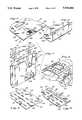
- FIG. 1is a perspective view of the present surgical drape resting on a patient while in use during surgery.
- FIG. 2is a perspective view of the surgical drape shown in FIG. 1 with the drape in a fully planar orientation.
- FIG. 3is a cross-sectional view of the drape shown in FIG. 2, taken along line 3--3.
- FIG. 4is an enlarged partial perspective view of a surgical instrument resting on a non-magnetized portion of the present surgical drape.
- FIG. 5is an enlarged, partially cutaway perspective view of the corner of the present surgical drape and the deformable metal strip embedded in the drape.
- FIG. 6is a perspective view of the portion of the drape shown in FIG. 5, with the deformable metal strip bent so as to cause a non-planar orientation of the periphery of the drape.
- FIG. 7is a partially cutaway perspective view of the pouch of the present invention.
- FIG. 8is a perspective view showing the pouch of the present invention secured to the surgical drape of the present invention.
- FIG. 9is a partial perspective view of a second embodiment of the present surgical drape, in a planar position.
- FIG. 10is a perspective view of the second embodiment of the present surgical drape, having a peripheral portion in a non-planar orientation.
- a patient 10is shown undergoing surgery.
- the patient 10is covered by sterile sheets, with an opening provided in the sheets for access to the portion of the patient's body being operated on, referred to as the surgical field 12.
- a plurality of commonly used surgical instruments 14, 15are shown resting on a surgical drape 16, constructed in accordance with one preferred embodiment of the present invention.
- the surgical drape 16is formed from a top layer 18 of a thin flexible sheet which is secured or bonded to a bottom layer 20 of a thin flexible sheet.
- the layers 18 and 20can be formed of rubber, or from a natural or synthetic thermoplastic.
- a plurality of rectangular instrument retaining magnets 22are secured to the drape 16 by embedding the magnets 22 within the drape, between the top and bottom layers 18, 20.
- the magnets 22are spaced apart sufficiently to permit flexibility of the drape 16.
- the top layer 18 of the drape 16defines an upwardly facing top surface 24 on which surgical instruments 14, 15 are rested, as shown in FIG. 1.
- the appropriate poles of the magnets 22are oriented sufficiently close to the top surface 24 so that the force of magnetic attraction between the magnets 22 and instruments 14 which are magnetizable retains those instruments 14 on the top surface 24 of the drape 16.
- the bottom layer 20 of the drape 16defines a bottom surface 25 which rests directly on the patient 10.
- the drape 16has a rectangular periphery which is defined by a pair of parallel short edges 26, and a parallel pair of long edges 28.
- a plurality of thin, elongate deformable strips 30are embedded within the drape 16 along peripheral portions 32 of the drape 16 adjacent the short edges 26.
- the deformable strips 30extend between the outermost rows of magnets 22 and the short edges 26 of the drape 16, and are oriented substantially normal to the short edges 26.
- the strips 30are embedded between the top and bottom layers 18, 20 of the drape -6. To avoid tearing of the layers 18, 20, the strips 30 have rounded corners 34. Also, as shown in FIG. 5, to avoid tearing of the drape 16 the strips 30 are sandwiched between layers of Dacron 36.
- the deformable stripe 30are formed from a thin metallic material, however, other types of material may be substituted in place of metal.
- FIG. 2illustrates an alternate embodiment in which elongate deformable strips 38 embedded within the drape 16 extend alongside and parallel to the long edges 28 of the drape 16. These longer strips 38 are sufficiently wide so as to bend along their entire length, as opposed to the shorter strips 30 which are bent across their width. Preferably, the long strips 38 are perforated to facilitate bonding of the strips 38 to the drape 16. It is to be understood that the drape 16 may either include the longer strips 38 and shorter strips 30 alone or in any one of a number of possible combinations.
- FIGS. 9 and 10Another embodiment of the invention is shown in FIGS. 9 and 10.
- a pair of peripheral magnets 40are secured to the drape 16 adjacent an edge, preferably a short edge 26.
- the peripheral magnets 40are spaced sufficiently far from the outermost instrument retaining magnets 22 so as to enable the drape 16 to be folded over between the instrument retaining magnets and peripheral magnets such that the magnets 22, 40 are superimposed, as in FIG. 10.
- the poles of the magnets 22, 40are oriented such that when superimposed, the magnets 22, 40 will be attracted, thus reversibly retaining the peripheral portion 32 of the drape 16 in a folded, non-planar configuration.
- a central portion of the drape 16has no magnets therein, thus forming a non-magnetized portion 42 of the drape 16.
- the non-magnetized portionis bordered by a lip 44 which rises above the top surface 24 of the drape 16.
- the lip 44is divided into a number of spaced, discreet segments so as to facilitate flexing and folding of the drape 16.
- a plurality of thin, hair-like filaments 46extend upwardly from the non-magnetized portion 42.
- each filament 46is tapered so as to narrow toward the top of the filament 46, which aids in the molding of the filaments 46.
- the non-magnetized portion 42is sufficiently large in area so that a non-magnetizable surgical instrument 15 may be retained within the non-magnetized portion 42 of the drape 16.
- the filaments 46are resilient and those directly under the instrument 15 will bend due to the weight of the instrument, as is best seen in FIG. 4.
- the unbent filaments 46 surrounding the instrument 15will thus aid in preventing sliding movement of the instrument 15 relative to the drape 40.
- the filaments 46may alternatively cover the entire top surface 24 of the drape 16, including magnetized portions.
- Holes 48are provided through the drape 16 adjacent the corners of the drape 16 to enable towel clamps (not shown) to be removably secured to the drape 16.
- the drape 16is laid on the patient 10 adjacent the surgical field 12.
- the flexibility of the drape 16permits the bottom surface 25 to conform to the patient 25, so that the drape 16 assumes a roughly cylindrical curvature about an axis parallel to its short edges 26.
- the peripheral portions 32 of the drape 16 adjacent the short edges 26are then deformed into a non-planar position, such that the peripheral portions 32 extend substantially normal to the remainder of the drape 16.
- magnetizable instruments 14are placed on the top surface 24 of the drape 16 for temporary storage.
- the instrument retaining magnets 22will cause the instruments 14 to be attracted to the drape 16, preventing the instruments 14 from sliding off the drape 16.
- Non-magnetizable instruments 15, and instruments on which a magnetic field will have a deleterious effect,are placed on the non-magnetizable portion 42 of the drape 16, where the filaments 46 and lip 44 aid in retaining the instrument 15 in place.
- the deformed peripheral portions 32 of the drape 16will stop the instrument 14, 15 from falling off the drape 16 completely.
- the peripheral portions 32are adjacent the ends of the drape 16 which assume the greatest slope from a horizontal plane, and thus are the most likely portions of the drape 16 from which instruments will fall.
- the pouch 50includes a substantially planar front wall 52 and a substantially planar back wall 54.
- the front and back walls 52, 54are substantially parallel and spaced from each other by means of ribs 56 which extend from the interior surfaces of the walls 52, 54.
- the ribs 56alternatively may be staggered relative to each other.
- the spacing between the walls 52, 54defines an opening 56 at the top of the pouch 50 through which surgical instruments (not shown) may be passed.
- the front and back walls 52, 54are joined along their lower ends by a bottom wall 58 which has a plurality of perforations 60 therein. Seams 62 are also provided to join the side edges of the front and back walls 52, 54.
- a pair of tabs 64are formed integral with the pouch 50.
- the tabs 64are configured to extend through slots 66 in the drape 16 to secure the pouch 50 to the drape 16.
- the tabs 64are formed by elongate necks 68 which extend upwardly from the back wall 54 of the pouch 50.
- the width of the neck 68is equal to or less than the length of the slot 66, so that the necks 68 can slide freely through the slots 66.
- the necks 68each terminate at a head 70 which is wider than the neck 68, and wider than the slot 66.
- the heads 70are formed from a flexible material so that they can be folded to reduce their width, enabling the head 70 to slip through the slot 66, as shown in broken lines in FIG. 7.
- the head 70includes a pair of rounded lobes 72 which depend downwardly from the head 70 on either side of the neck 68.
- the lobes 72extend beyond the point of attachment between the head 70 and the neck 68 so that the lobes 72 overlap the slot 66 and prevent the head 70 from being drawn through the slot 60, so as to support the weight of the pouch 50 and any instruments retained therein.
- the entire pouch 50may be formed from a single sheet of flexible material which is folded about the bottom wall 58 and heat sealed together along the side seams 62.
- the perforations 60 and the tabs 64can be die cut from the sheet.
- the pouch 50is secured to the drape -6 by passing the heads 70 of the tabs 64 through the slots 66 and drawing the heads 70 back so that the lobes 72 overlap the slots 66.
- various instrumentsare placed in the pouch 50 for storage, such as cautery devices and suction devices which are too large to be placed on the drape 16 or which have hoses or wires extending therefrom which would become entangled with the other instruments 14, 15 on the drape 16. While in the pouch 50, liquids on the instruments can drain through the perforations 60.
- the pouch 50is removed from the drape 16 by folding the tab heads 70 and drawing them through the slots 66.
- the pouch 50can then be sterilized by any of a number of means, such as in a gas or steam autoclave (not shown). Since the ribs 56 maintain the front and back walls 52, 54 of the pouch 50 spaced apart, fluids can enter the pouch 50 through the opening 56 when in the autoclave.
- the perforations 60 in the bottom wall 58also encourage the passage of fluids through the pouch 50, further aiding sterilization. Since the tabs 64 are integral with the pouch 50, no additional handling is required during sterilization, nor can the tabs 64 be misplaced.
- the pouch 50is reusable after sterilization.
- the pouch 50may be secured to any of a variety of structures having slots therein, although in the preferred embodiment the pouch 50 is attached to the magnetic drape 16 of the present invention.
Landscapes
- Health & Medical Sciences (AREA)
- Surgery (AREA)
- Life Sciences & Earth Sciences (AREA)
- Engineering & Computer Science (AREA)
- Biomedical Technology (AREA)
- Heart & Thoracic Surgery (AREA)
- Medical Informatics (AREA)
- Molecular Biology (AREA)
- Animal Behavior & Ethology (AREA)
- General Health & Medical Sciences (AREA)
- Public Health (AREA)
- Veterinary Medicine (AREA)
- Surgical Instruments (AREA)
Abstract
Description
This application is a division of application Ser. No. 166,480 ,filed March 9, 1988. New U.S. Pat. No. 4,944,311.
The present invention relates generally to the field of devices for retaining surgical instrument and more particularly to a surgical drape on which surgical instruments can be retained during surgery, and a pouch attached to the drape for the same purpose.
During surgery a wide variety of instruments are used by the surgeon, requiring the surgeon to frequently lay one instrument down on a sterile surface and then pick up another. To facilitate this handling of instruments, sterile magnetic surgical drapes have been developed which are laid on top of the patient, proximate the surgical field. The instruments can be laid on the drape by the surgeon and subsequently picked up without requiring time consuming reaching by the surgeon. Since these drapes conform to the patient, magnets are embedded in the drape to magnetically attract the instruments to the drape and prevent the instruments from sliding off the drape and onto the floor.
A major drawback of these prior magnetic surgical drapes is that instruments fabricated from a non-magnetizable material, such as plastic or brass, will not adhere to the drape. Further, certain magnetizable instruments are adversely affected by proximity to a magnetic field. For example, it is critical that needle clamps release a needle when desired. However, if the needle clamp or needle is exposed to a magnetic field and either becomes magnetized, then a magnetic attraction between the needle clamp and needle will prevent release of the needle at the desired time.
Another difficulty encountered with prior magnetic drapes has been that even magnetizable instruments have a tendency to fall off the drape if they are placed between the magnets. In addition to requiring resterilization, instruments that fall on the floor are an annoyance which can break the concentration of the surgeon. Also, falling instruments which enter the surgical field, or which are sharp, can be hazardous.
Another device which has been developed for retaining surgical instruments near the surgical field is a pouch which is secured to a surgical drape by means of towel clamps or tape. Previously, these pouches have not been reusable since they were unable to be effectively sterilized, thus limiting their usefulness. Another drawback of these pouches has been the difficulty associated with manipulating the towel clamps, which are separate from the pouch itself.
Thus, a need exists for a surgical drape on which non-magnetizable surgical instruments can be retained, and which prevents instruments from falling off the drape. Further, a need exists for a pouch which retains surgical instruments and which is reusable.
Briefly, the present invention is an apparatus for retaining surgical instruments adjacent a surgical field. The apparatus comprises a drape having a top surface on which surgical instruments are rested, and a bottom surface which lays on a patient. The drape is flexible so that the bottom surface of the drape conforms to the patient. A plurality of magnets are secured to the drape to retain surgical instruments which are placed on the top surface of the drape. The instrument-retaining magnets are oriented so that when a magnetizable surgical instrument is placed on the top surface of the drape, the force of magnetic attraction between the magnet and the instrument will cause the instrument to be retained in place.
A unique feature of the present invention is that a peripheral portion of the drape is maintained in a non- planar configuration. Advantageously, the peripheral portion prevents surgical instruments from falling off the drape in the event that insufficient magnetic attraction is achieved to retain the instrument on the top surface of the drape. Thus, the present drape minimizes the likelihood of instruments contacting non-sterile surfaces, or falling out of reach of the surgeon.
Preferably, the non-planar configuration of the peripheral portion of the drape is maintained by a means for reversibly causing deformation of the peripheral portion. For example, the deformation-causing means can comprise a deformable strip of metallic material secured to the drape by embedding the strip within the drape. Alternatively, deformation-causing means may comprise a peripheral magnet secured to the drape adjacent the non- planar peripheral portion. The peripheral magnet is spaced from the instrument-retaining magnets and oriented so that upon folding the drape along the space between the peripheral and instrument-retaining magnet, the magnets will be attracted when superimposed upon one another and will maintain the peripheral portion in a folded, non- planar position.
Since the peripheral portion can be reversibly deformed into a planar or non-planar configuration, the present surgical drape can be laid flat for easy shipping and handling, and also can be folded into a compact, planar shape.
Another feature of the present invention is the flexible surgical drape having a plurality of filaments extending upwardly from the top surface of the drape. The filaments engage a surgical instrument placed on the drape so as to prevent sliding of the instrument relative to the drape. Preferably, the filaments are sufficiently resilient in bending so as to deform under the weight of the surgical instrument which is placed directly on the filaments, and so that the adjacent filaments which are not caused to bend will surround and retain the surgical instruments on the top surface of the drape.
Advantageously, the filaments may be located on a non- magnetized portion of the drape which encompasses a sufficient area on the top surface of the drape so as to rest thereon a non-magnetizable surgical instruments or surgical instruments to which application of a magnetic field will have a deleterious effect. Preferably, a raised lip surrounds the non-magnetized portion of the drape so as to further aid in retaining instruments on the non- magnetized portion. As a result, the present surgical drape can be used in combination with surgical instruments which otherwise could not be retained in place on a drape which relied solely on magnets for retaining the instruments in place.
Another feature of the invention is a pouch in which surgical instruments may be stored. The pouch is comprised of a pair of substantially planar, spaced walls. The space between the walls defines an opening through which surgical instruments are inserted and withdrawn from the pouch. At least one rib extends along one of the walls that engages the other wall to maintain the walls in a spaced relationship. A major advantage of the present pouch as compared to the prior art is that access is permitted to the interior of the present pouch so that it can be sterilized and reused. To further aid in sterilization, the present pouch preferably includes a bottom wall which extends between the spaced walls, with the bottom wall including a plurality of perforations therein to allow passage of fluids therethrough.
Preferably, the present pouch can be removably secured to a surgical drape such as the instrument-retaining surgical drape of the present invention. The attachment means comprises a tab which mates with the slot in the surgical drape to removably secure the pouch to the drape. The tab itself comprises a neck extending from the pouch. The neck is sized to pass through the slot and terminates at one end in a head which is secured to the end of the neck. The head has a width greater than the slot so as to secure the neck to the slot. The head is bendable to reduce its width for passage of the head through the slot for attachment or removal of the pouch from the drape. The tabs can be reused after sterilization, unlike the prior art pouches which relied on tape to attach the pouch to a drape.
Advantageously, the entire pouch, including the tabs, can be formed from a single continuous sheet of flexible material which is folded over on itself and sealed at its sides to enclose the pouch. This construction technique is simple and economical, thus reducing the cost of producing the pouch. Further, since the tabs are integral with the pouch, no additional handling is required for the tabs, as opposed to the prior art towel clamps.
FIG. 1 is a perspective view of the present surgical drape resting on a patient while in use during surgery.
FIG. 2 is a perspective view of the surgical drape shown in FIG. 1 with the drape in a fully planar orientation.
FIG. 3 is a cross-sectional view of the drape shown in FIG. 2, taken alongline 3--3.
FIG. 4 is an enlarged partial perspective view of a surgical instrument resting on a non-magnetized portion of the present surgical drape.
FIG. 5 is an enlarged, partially cutaway perspective view of the corner of the present surgical drape and the deformable metal strip embedded in the drape.
FIG. 6 is a perspective view of the portion of the drape shown in FIG. 5, with the deformable metal strip bent so as to cause a non-planar orientation of the periphery of the drape.
FIG. 7 is a partially cutaway perspective view of the pouch of the present invention.
FIG. 8 is a perspective view showing the pouch of the present invention secured to the surgical drape of the present invention.
FIG. 9 is a partial perspective view of a second embodiment of the present surgical drape, in a planar position.
FIG. 10 is a perspective view of the second embodiment of the present surgical drape, having a peripheral portion in a non-planar orientation.
Referring to FIG. 1, apatient 10 is shown undergoing surgery. Thepatient 10 is covered by sterile sheets, with an opening provided in the sheets for access to the portion of the patient's body being operated on, referred to as thesurgical field 12. A plurality of commonly usedsurgical instruments surgical drape 16, constructed in accordance with one preferred embodiment of the present invention.
As is best seen in FIG. 3, thesurgical drape 16 is formed from atop layer 18 of a thin flexible sheet which is secured or bonded to abottom layer 20 of a thin flexible sheet. Thelayers
A plurality of rectangularinstrument retaining magnets 22 are secured to thedrape 16 by embedding themagnets 22 within the drape, between the top andbottom layers magnets 22 are spaced apart sufficiently to permit flexibility of thedrape 16. Thetop layer 18 of thedrape 16 defines an upwardly facingtop surface 24 on whichsurgical instruments magnets 22 are oriented sufficiently close to thetop surface 24 so that the force of magnetic attraction between themagnets 22 andinstruments 14 which are magnetizable retains thoseinstruments 14 on thetop surface 24 of thedrape 16. Thebottom layer 20 of thedrape 16 defines abottom surface 25 which rests directly on thepatient 10.
Thedrape 16 has a rectangular periphery which is defined by a pair of parallelshort edges 26, and a parallel pair oflong edges 28. As is best seen in Figures 2, 5 and 6, a plurality of thin, elongatedeformable strips 30 are embedded within thedrape 16 alongperipheral portions 32 of thedrape 16 adjacent the short edges 26. The deformable strips 30 extend between the outermost rows ofmagnets 22 and theshort edges 26 of thedrape 16, and are oriented substantially normal to the short edges 26. As illustrated in FIG. 5, thestrips 30 are embedded between the top andbottom layers layers strips 30 have roundedcorners 34. Also, as shown in FIG. 5, to avoid tearing of thedrape 16 thestrips 30 are sandwiched between layers ofDacron 36.
When a manual bending force is applied to thestrips 30, deformation of thestrips 30 results, causing theperipheral portions 32 of thedrape 16 in which thestrips 30 are embedded to assume the contour of thestrips 30. Thus, theperipheral portions 32 of thedrape 16 can be maintained in a bent or non-planar configuration, as seen in FIGS. 1 and 6. The deformation of thestrips 30 can be reversed so as to return thestrips 30 and theperipheral portions 32 to a planar orientation, as in FIGS. 2 and 5. Preferably, thedeformable stripe 30 are formed from a thin metallic material, however, other types of material may be substituted in place of metal.
FIG. 2 illustrates an alternate embodiment in which elongatedeformable strips 38 embedded within thedrape 16 extend alongside and parallel to thelong edges 28 of thedrape 16. These longer strips 38 are sufficiently wide so as to bend along their entire length, as opposed to theshorter strips 30 which are bent across their width. Preferably, thelong strips 38 are perforated to facilitate bonding of thestrips 38 to thedrape 16. It is to be understood that thedrape 16 may either include the longer strips 38 andshorter strips 30 alone or in any one of a number of possible combinations.
Another embodiment of the invention is shown in FIGS. 9 and 10. In order to maintain theperipheral portions 32 of thedrape 16 in a bent or non-planar orientation, a pair ofperipheral magnets 40 are secured to thedrape 16 adjacent an edge, preferably ashort edge 26. Theperipheral magnets 40 are spaced sufficiently far from the outermostinstrument retaining magnets 22 so as to enable thedrape 16 to be folded over between the instrument retaining magnets and peripheral magnets such that themagnets magnets magnets peripheral portion 32 of thedrape 16 in a folded, non-planar configuration.
Referring now to FIGS.1 through 4, a central portion of thedrape 16 has no magnets therein, thus forming anon-magnetized portion 42 of thedrape 16. The non-magnetized portion is bordered by alip 44 which rises above thetop surface 24 of thedrape 16. Thelip 44 is divided into a number of spaced, discreet segments so as to facilitate flexing and folding of thedrape 16. A plurality of thin, hair-like filaments 46 extend upwardly from thenon-magnetized portion 42. Preferably, eachfilament 46 is tapered so as to narrow toward the top of thefilament 46, which aids in the molding of thefilaments 46.
Thenon-magnetized portion 42 is sufficiently large in area so that a non-magnetizablesurgical instrument 15 may be retained within thenon-magnetized portion 42 of thedrape 16. Thefilaments 46 are resilient and those directly under theinstrument 15 will bend due to the weight of the instrument, as is best seen in FIG. 4. Theunbent filaments 46 surrounding theinstrument 15 will thus aid in preventing sliding movement of theinstrument 15 relative to thedrape 40. Although not shown, thefilaments 46 may alternatively cover the entiretop surface 24 of thedrape 16, including magnetized portions.
In operation, thedrape 16 is laid on the patient 10 adjacent thesurgical field 12. The flexibility of thedrape 16 permits thebottom surface 25 to conform to thepatient 25, so that thedrape 16 assumes a roughly cylindrical curvature about an axis parallel to itsshort edges 26. Theperipheral portions 32 of thedrape 16 adjacent theshort edges 26 are then deformed into a non-planar position, such that theperipheral portions 32 extend substantially normal to the remainder of thedrape 16.
During the course of surgery,magnetizable instruments 14 are placed on thetop surface 24 of thedrape 16 for temporary storage. Theinstrument retaining magnets 22 will cause theinstruments 14 to be attracted to thedrape 16, preventing theinstruments 14 from sliding off thedrape 16.Non-magnetizable instruments 15, and instruments on which a magnetic field will have a deleterious effect, are placed on thenon-magnetizable portion 42 of thedrape 16, where thefilaments 46 andlip 44 aid in retaining theinstrument 15 in place.
In the event aninstrument drape 16 in such a manner that it is not properly retained by thedrape 16, the deformedperipheral portions 32 of thedrape 16 will stop theinstrument drape 16 completely. By aligning the deformedperipheral portions 32 parallel to the axis of curvature of thedrape 16, theperipheral portions 32 are adjacent the ends of thedrape 16 which assume the greatest slope from a horizontal plane, and thus are the most likely portions of thedrape 16 from which instruments will fall.
Turning now to FIG. 7 and 8, apouch 50 is shown which is designed to be removably attached to thedrape 16. Thepouch 50 includes a substantially planarfront wall 52 and a substantiallyplanar back wall 54. The front andback walls ribs 56 which extend from the interior surfaces of thewalls ribs 56 alternatively may be staggered relative to each other. The spacing between thewalls opening 56 at the top of thepouch 50 through which surgical instruments (not shown) may be passed.
The front andback walls bottom wall 58 which has a plurality ofperforations 60 therein.Seams 62 are also provided to join the side edges of the front andback walls
To removably secure thepouch 50 to thedrape 16, a pair oftabs 64 are formed integral with thepouch 50. Thetabs 64 are configured to extend throughslots 66 in thedrape 16 to secure thepouch 50 to thedrape 16. Thetabs 64 are formed byelongate necks 68 which extend upwardly from theback wall 54 of thepouch 50. The width of theneck 68 is equal to or less than the length of theslot 66, so that thenecks 68 can slide freely through theslots 66. Thenecks 68 each terminate at ahead 70 which is wider than theneck 68, and wider than theslot 66. Theheads 70 are formed from a flexible material so that they can be folded to reduce their width, enabling thehead 70 to slip through theslot 66, as shown in broken lines in FIG. 7.
To prevent unwanted slippage of thehead 70 back out of theslot 66, thehead 70 includes a pair ofrounded lobes 72 which depend downwardly from thehead 70 on either side of theneck 68. Thelobes 72 extend beyond the point of attachment between thehead 70 and theneck 68 so that thelobes 72 overlap theslot 66 and prevent thehead 70 from being drawn through theslot 60, so as to support the weight of thepouch 50 and any instruments retained therein.
Theentire pouch 50 may be formed from a single sheet of flexible material which is folded about thebottom wall 58 and heat sealed together along the side seams 62. Theperforations 60 and thetabs 64 can be die cut from the sheet.
In operation, thepouch 50 is secured to the drape -6 by passing theheads 70 of thetabs 64 through theslots 66 and drawing theheads 70 back so that thelobes 72 overlap theslots 66. During surgery, various instruments are placed in thepouch 50 for storage, such as cautery devices and suction devices which are too large to be placed on thedrape 16 or which have hoses or wires extending therefrom which would become entangled with theother instruments drape 16. While in thepouch 50, liquids on the instruments can drain through theperforations 60.
After surgery, thepouch 50 is removed from thedrape 16 by folding the tab heads 70 and drawing them through theslots 66. Thepouch 50 can then be sterilized by any of a number of means, such as in a gas or steam autoclave (not shown). Since theribs 56 maintain the front andback walls pouch 50 spaced apart, fluids can enter thepouch 50 through theopening 56 when in the autoclave. Theperforations 60 in thebottom wall 58 also encourage the passage of fluids through thepouch 50, further aiding sterilization. Since thetabs 64 are integral with thepouch 50, no additional handling is required during sterilization, nor can thetabs 64 be misplaced. Thepouch 50 is reusable after sterilization.
It is to be understood that thepouch 50 may be secured to any of a variety of structures having slots therein, although in the preferred embodiment thepouch 50 is attached to themagnetic drape 16 of the present invention.
Although the present invention has been described with reference to the preferred embodiments, numerous modifications and rearrangements can be made which will still come within the scope of the invention.
Claims (14)
1. An apparatus for retaining surgical instruments adjacent a surgical field, comprising:
drape having a top surface on which surgical instruments are rested and a bottom surface which lays entirely on a patient, said drape being flexible so as to conform to said patient;
plurality of instrument-retaining magnets secured to said drape and oriented so that when a magnetizable surgical instrument is placed on said top surface of said drape adjacent one of said magnets, the force of magnetic attraction between said magnet and said instrument will cause said instrument to be retained in place on said top surface of said drape;
a peripheral portion of said drape being maintained in a non-planar configuration by extending upwardly, away from said patient, said peripheral portion preventing surgical instruments from falling off said drape during a surgical procedure in the event that insufficient magnetic attraction is achieved to retain said instrument on said top surface, said drape thereby retaining and providing access to said surgical instruments so as t enable repeated placement of said instruments on said drape and removal of said instruments from said drape during the course of a surgical procedure; and
means for reversibly causing deformation of said peripheral portion of said drape, said deformation causing means maintaining said non-planar configuration of said peripheral portion.
2. The apparatus of claim 1, wherein said deformation causing means comprises a deformable strip of metallic material secured to said drape.
3. The apparatus of claim 2, wherein said deformable strip has a plurality of apertures and is embedded within said drape.
4. The apparatus of claim 2, wherein:
said peripheral portion is defined by an edge of said drape; and
said strip being elongate and extending substantially normal to said edge.
5. The apparatus of claim 4, wherein said strip extends between said magnets and said edge.
6. The apparatus of claim 2, wherein said strip has rounded corners.
7. The apparatus of claim 1, wherein said deformation causing means comprises a peripheral magnet secured to said drape adjacent said peripheral portion, said peripheral magnet being spaced from said instrument retaining magnets and oriented so that, upon folding said drape along said space between said peripheral and instrument retaining magnets, said magnets will be magnetically attracted when superimposed on one another and will maintain said peripheral portion in a folded, non-planar position.
8. The apparatus of claim 1, wherein said drape further comprises an integral, non-magnetized portion which encompasses a sufficient area on said top surface of said drape so as to rest thereon non-magnetizable surgical instruments or surgical instruments to which application of a magnetic field will have a deleterious effect.
9. The apparatus of claim 8, wherein said non-magnetized portion is flexible and is surrounded by a flexible lip which is raised above said top surface, so as to aid in retaining said instruments on said non-magnetized portion.
10. The apparatus of claim 9, wherein said non-magnetized portion is substantially centered within said drape and is surrounded by said magnets.
11. The apparatus of claim 1, wherein said peripheral portion is integral with said drape.
12. An apparatus for retaining surgical instruments adjacent a surgical field, comprising:
a drape having a top surface on which surgical instruments are rested and a bottom surface which lays entirely on a patient, said drape being flexible so as to conform to said patient;
a plurality of instrument-retaining magnets secured to said drape and oriented so that, when a magnetizable surgical instrument is placed on said top surface of said drape adjacent one of said magnets, the force of magnetic attraction between said magnet and said instrument will cause said instrument to be retained in place on said top surface of said drape; and
a non-magnetized portion of said drape which encompasses a sufficient area on said top surface of said drape so as to rest thereon non-magnetizable surgical instruments or surgical instruments to which application of a magnetic field will have a deleterious effect wherein said non-magnetized portion is positioned substantially within the center of said drape.
13. The apparatus of claim 12, wherein said non-magnetized portion is integral with said drape.
14. An apparatus for retaining surgical instruments adjacent a surgical field, comprising:
a drape having a top surface on which surgical instruments are rested and a bottom surface which lays entirely on a patient, said drape being flexible so as to conform to said patient;
a plurality of instrument-retaining magnets secured to said drape and oriented so that, when a magnetizable surgical instrument is placed on said top surface of said drape adjacent one of said magnets, the force of magnetic attraction between said magnet and said instrument will cause said instrument to be retained in place on said top surface of said drape; and
a non-magnetized portion of said drape which encompasses a sufficient area on said top surface of said drape so as to rest thereon non-magnetizable surgical instruments or surgical instruments to which application of a magnetic field will have a deleterious effect, wherein said non-magnetized portion is flexible and is surrounded by a flexible lip which is raised above said top surface, so as to aid in retaining said instruments on said non-magnetized portion.
Priority Applications (1)
| Application Number | Priority Date | Filing Date | Title |
|---|---|---|---|
| US07/474,477US5036866A (en) | 1988-03-09 | 1990-02-02 | Surgical instrument retainer |
Applications Claiming Priority (2)
| Application Number | Priority Date | Filing Date | Title |
|---|---|---|---|
| US07/166,480US4944311A (en) | 1988-03-09 | 1988-03-09 | Surgical instrument retainer |
| US07/474,477US5036866A (en) | 1988-03-09 | 1990-02-02 | Surgical instrument retainer |
Related Parent Applications (1)
| Application Number | Title | Priority Date | Filing Date |
|---|---|---|---|
| US07/166,480ContinuationUS4944311A (en) | 1988-03-09 | 1988-03-09 | Surgical instrument retainer |
Publications (1)
| Publication Number | Publication Date |
|---|---|
| US5036866Atrue US5036866A (en) | 1991-08-06 |
Family
ID=26862300
Family Applications (1)
| Application Number | Title | Priority Date | Filing Date |
|---|---|---|---|
| US07/474,477Expired - LifetimeUS5036866A (en) | 1988-03-09 | 1990-02-02 | Surgical instrument retainer |
Country Status (1)
| Country | Link |
|---|---|
| US (1) | US5036866A (en) |
Cited By (60)
| Publication number | Priority date | Publication date | Assignee | Title |
|---|---|---|---|---|
| USD378408S (en)* | 1995-05-31 | 1997-03-11 | Tecnol Medical Products, Inc. | Cord and tube organizer |
| USD402767S (en) | 1997-08-27 | 1998-12-15 | Davis Steven J | Laparoscopic surgery tray |
| US5848693A (en)* | 1997-11-04 | 1998-12-15 | Davis; Steven J. | Laparoscopic surgical tray with apertured clips |
| WO2000048526A1 (en)* | 1999-02-18 | 2000-08-24 | Technovent Ltd. | Mat for retaining surgical instruments |
| WO2000032111A3 (en)* | 1998-12-03 | 2000-10-05 | Canica Design Inc | Surgical fixation and retraction system |
| US6165625A (en)* | 1996-12-19 | 2000-12-26 | Kimberly-Clark Worldwide, Inc. | Method of making high intensity light resistant instrument pads |
| US6308875B1 (en) | 1999-08-11 | 2001-10-30 | Kristi M. Almo | Surgical instrument storage pack |
| US20030060831A1 (en)* | 2001-08-28 | 2003-03-27 | Bonutti Peter M. | Surgical draping system |
| US20030163160A1 (en)* | 2000-05-10 | 2003-08-28 | O'malley Michael T | System and method for moving and stretching plastic tissue |
| US6673409B1 (en) | 2001-07-31 | 2004-01-06 | American Covers, Inc. | Frictional holding pad |
| US20040169091A1 (en)* | 2003-02-28 | 2004-09-02 | American Covers, Inc. | Air freshener and method |
| US20050167522A1 (en)* | 2003-02-28 | 2005-08-04 | American Covers, Inc. | Air freshener and method |
| US20050169793A1 (en)* | 2003-02-28 | 2005-08-04 | American Covers, Inc. | Air freshener and method |
| US20050199668A1 (en)* | 2001-07-31 | 2005-09-15 | American Covers, Inc. | Frictional holding pad |
| US20050200441A1 (en)* | 2004-03-15 | 2005-09-15 | Yuhito Doi | Permanent magnet package, method for manufacturing same, and method for transporting permanent magnet |
| USD511568S1 (en) | 2004-05-05 | 2005-11-15 | American Covers, Inc. | Air freshener |
| USD514679S1 (en) | 2004-05-05 | 2006-02-07 | American Covers, Inc. | Air freshener |
| US20060064125A1 (en)* | 2001-05-09 | 2006-03-23 | James Henderson | Button anchor system for moving tissue |
| US20060121250A1 (en)* | 2001-07-31 | 2006-06-08 | Wheatley Alan J | Frictional holding pad |
| US20060196964A1 (en)* | 2003-02-28 | 2006-09-07 | Wheatley Alan J | Air freshener and method |
| US20060219249A1 (en)* | 2005-04-04 | 2006-10-05 | Czajka Francis A | Surgical drape with a pouch |
| US7119689B2 (en) | 2003-09-19 | 2006-10-10 | Vesta Medical, Llc | System and method for sorting medical waste for disposal |
| US20060272979A1 (en)* | 2005-06-07 | 2006-12-07 | Lubbers Lawrence M | Surgical Tray |
| US20070107130A1 (en)* | 2005-11-16 | 2007-05-17 | Basim Elhabashy | Surgical coordinator for anesthesiologist and methods of use |
| EP1545374A4 (en)* | 2002-06-06 | 2007-08-01 | Surgisafe Pty Ltd | Holder for surgical instruments |
| US7275645B2 (en) | 2003-09-19 | 2007-10-02 | Vesta Medical, Llc | Handheld medical waste sorting device |
| USD555571S1 (en)* | 2004-12-27 | 2007-11-20 | Eskandry Ezra D | Anti-skid mat for accessories in an automobile |
| US7303081B2 (en) | 2003-09-19 | 2007-12-04 | Vesta Medical, Llc | Handheld medical waste sorting method |
| US7311207B2 (en) | 2003-09-19 | 2007-12-25 | Vesta Medical, Llc | System for sorting discarded and spent pharmaceutical items |
| US7318529B2 (en) | 2003-09-19 | 2008-01-15 | Vest Medical, Llc | Method for sorting discarded and spent pharmaceutical items |
| US7361185B2 (en) | 2001-05-09 | 2008-04-22 | Canica Design, Inc. | Clinical and surgical system and method for moving and stretching plastic tissue |
| WO2008085919A3 (en)* | 2007-01-03 | 2008-09-25 | Tyco Healthcare | Surgical system having a magnetic entry |
| US20090072045A1 (en)* | 2003-02-28 | 2009-03-19 | Wheatley Alan J | Air Freshener and Method |
| US7562025B2 (en) | 2003-09-19 | 2009-07-14 | Vesta Medical, Llc | Waste sorting system with query function, and method thereof |
| US20090267717A1 (en)* | 2008-04-24 | 2009-10-29 | Baskett Michael D | Magnetic Mat for Holding Surgical Instruments |
| US20100001151A1 (en)* | 2001-07-31 | 2010-01-07 | Wheatley Alan J | Frictional dash mount for a global positional system |
| US7660724B2 (en) | 2003-09-19 | 2010-02-09 | Vesta Medical, Llc | Waste sorting system utilizing removable liners |
| US20100171020A1 (en)* | 2009-01-06 | 2010-07-08 | Icc Innovative Concepts Corporation | Caddy for car dashboard |
| US20110052858A1 (en)* | 2009-08-26 | 2011-03-03 | Gma Industries Llc | Formable Tray |
| US7970722B1 (en) | 1999-11-08 | 2011-06-28 | Aloft Media, Llc | System, method and computer program product for a collaborative decision platform |
| US8195328B2 (en) | 2003-09-19 | 2012-06-05 | Vesta Medical, Llc | Combination disposal and dispensing apparatus and method |
| WO2012084198A1 (en)* | 2010-12-23 | 2012-06-28 | Straumann Holding Ag | Cassette for storage of medical instruments |
| US8490846B1 (en) | 2011-01-10 | 2013-07-23 | American Covers, Inc. | Frictional holding pad with inclined grip |
| US8501294B1 (en) | 2009-12-29 | 2013-08-06 | American Covers, Inc. | Friction pad on dashboard for portable handheld electronic device |
| US8518510B1 (en) | 2009-12-29 | 2013-08-27 | American Covers, Inc. | Friction pad on portable handheld electronic device |
| US20130327663A1 (en)* | 2012-06-11 | 2013-12-12 | Brett Telford | Surgical Instrument Holder |
| US20140299739A1 (en)* | 2013-04-08 | 2014-10-09 | Bradeaux LLC | Personal Magnetic Surgical Instrument System |
| US9486293B2 (en) | 2010-04-29 | 2016-11-08 | Cook Medical Technologies Llc | Surgical drape kit |
| US9622773B2 (en) | 2012-03-19 | 2017-04-18 | Aspen Surgical Products, Inc. | Side activated safety scalpel for left and right hand users with blade removal system |
| USD813390S1 (en) | 2016-01-15 | 2018-03-20 | Aspen Surgical Products, Inc. | Surgical scalpel blade attachment |
| US9936948B2 (en)* | 2014-04-25 | 2018-04-10 | Sharp Fluidics Llc | Systems and methods for increased operating room efficiency |
| US10299825B2 (en) | 2014-10-03 | 2019-05-28 | Aspen Surgical Products, Inc. | Sharps blade applicator and storage device |
| US10456210B2 (en)* | 2016-04-26 | 2019-10-29 | Seonghum JUNG | Surgical instrument organizing pad |
| US10478177B2 (en) | 2015-10-29 | 2019-11-19 | Sharp Fluidics Llc | Systems and methods for increased operating room efficiency |
| US10574801B1 (en) | 2019-01-11 | 2020-02-25 | Handstands Promo, Llc | Grip pad |
| WO2020120938A3 (en)* | 2018-12-10 | 2020-07-23 | Madigan Jeremy | Surgical apparatus |
| US11278310B2 (en) | 2016-03-21 | 2022-03-22 | Aspen Surgical Products, Inc. | Safety scalpel handle |
| US20220285062A1 (en)* | 2015-01-13 | 2022-09-08 | Martha Sue Pearson-Monti | Sharps medical instrument organizer |
| US11478320B2 (en)* | 2015-08-06 | 2022-10-25 | Jacobs Emerging Technologies, Llc | Medical device holder |
| US20240299115A1 (en)* | 2023-03-07 | 2024-09-12 | Surgical Compass LLC | Cervicothoracic mat |
Citations (19)
| Publication number | Priority date | Publication date | Assignee | Title |
|---|---|---|---|---|
| US3201028A (en)* | 1964-07-21 | 1965-08-17 | Wolf Brothers Inc | Container |
| US3262283A (en)* | 1964-12-18 | 1966-07-26 | Yates Dowell A | Refrigerating jacket |
| US3456865A (en)* | 1967-10-26 | 1969-07-22 | Carl H Frank | Carrying bag having oppositely curved slots in upper panel portions of bag and flexible removable handle |
| US3482567A (en)* | 1967-04-12 | 1969-12-09 | American Hospital Supply Corp | Disposable surgical drape construction |
| US3483494A (en)* | 1965-09-03 | 1969-12-09 | Surgitool Inc | Magnetic surgical drape |
| US3522800A (en)* | 1966-07-19 | 1970-08-04 | Arthur J Lesser | Disposable wound retractor and drape and method of using same |
| US3546643A (en)* | 1969-01-16 | 1970-12-08 | Catherine A Virostek | Pad for surgical instruments or the like |
| US3654047A (en)* | 1970-01-12 | 1972-04-04 | Howard Berkowitz | Surgical instrument holder |
| US3727658A (en)* | 1971-09-22 | 1973-04-17 | Instranetics Inc | Receiver for surgical implements |
| US3861521A (en)* | 1973-04-17 | 1975-01-21 | Mildred V Burtz | Disposable suture organizer |
| US4013109A (en)* | 1975-08-22 | 1977-03-22 | Dan Sandel | Disposable container for surgical instruments |
| US4051845A (en)* | 1976-03-05 | 1977-10-04 | The Kendall Company | Drape assembly with pouch and method |
| US4100684A (en)* | 1976-06-21 | 1978-07-18 | Stuart Berger | Holder device for paper articles and writing instruments |
| US4169472A (en)* | 1978-04-17 | 1979-10-02 | Johnson & Johnson | Surgical drape |
| US4336806A (en)* | 1980-05-07 | 1982-06-29 | Instranetics, Inc. | Medical tubing holder |
| US4485919A (en)* | 1982-08-12 | 1984-12-04 | Dan Sandel | Sterilizable foam support tray for medical instruments |
| US4524767A (en)* | 1982-07-06 | 1985-06-25 | Glassman Jacob A | Surgical drapes |
| US4733806A (en)* | 1980-03-26 | 1988-03-29 | Sloop Conrad B | Case |
| US4944311A (en)* | 1988-03-09 | 1990-07-31 | Jodel Medical Products, Inc. | Surgical instrument retainer |
- 1990
- 1990-02-02USUS07/474,477patent/US5036866A/ennot_activeExpired - Lifetime
Patent Citations (20)
| Publication number | Priority date | Publication date | Assignee | Title |
|---|---|---|---|---|
| US3201028A (en)* | 1964-07-21 | 1965-08-17 | Wolf Brothers Inc | Container |
| US3262283A (en)* | 1964-12-18 | 1966-07-26 | Yates Dowell A | Refrigerating jacket |
| US3483494A (en)* | 1965-09-03 | 1969-12-09 | Surgitool Inc | Magnetic surgical drape |
| US3522800A (en)* | 1966-07-19 | 1970-08-04 | Arthur J Lesser | Disposable wound retractor and drape and method of using same |
| US3482567A (en)* | 1967-04-12 | 1969-12-09 | American Hospital Supply Corp | Disposable surgical drape construction |
| US3456865A (en)* | 1967-10-26 | 1969-07-22 | Carl H Frank | Carrying bag having oppositely curved slots in upper panel portions of bag and flexible removable handle |
| US3546643A (en)* | 1969-01-16 | 1970-12-08 | Catherine A Virostek | Pad for surgical instruments or the like |
| US3654047A (en)* | 1970-01-12 | 1972-04-04 | Howard Berkowitz | Surgical instrument holder |
| US3727658A (en)* | 1971-09-22 | 1973-04-17 | Instranetics Inc | Receiver for surgical implements |
| US3861521A (en)* | 1973-04-17 | 1975-01-21 | Mildred V Burtz | Disposable suture organizer |
| US4013109A (en)* | 1975-08-22 | 1977-03-22 | Dan Sandel | Disposable container for surgical instruments |
| US4013109B1 (en)* | 1975-08-22 | 1995-04-25 | Dan Sandel | Disposable container for surgical instruments. |
| US4051845A (en)* | 1976-03-05 | 1977-10-04 | The Kendall Company | Drape assembly with pouch and method |
| US4100684A (en)* | 1976-06-21 | 1978-07-18 | Stuart Berger | Holder device for paper articles and writing instruments |
| US4169472A (en)* | 1978-04-17 | 1979-10-02 | Johnson & Johnson | Surgical drape |
| US4733806A (en)* | 1980-03-26 | 1988-03-29 | Sloop Conrad B | Case |
| US4336806A (en)* | 1980-05-07 | 1982-06-29 | Instranetics, Inc. | Medical tubing holder |
| US4524767A (en)* | 1982-07-06 | 1985-06-25 | Glassman Jacob A | Surgical drapes |
| US4485919A (en)* | 1982-08-12 | 1984-12-04 | Dan Sandel | Sterilizable foam support tray for medical instruments |
| US4944311A (en)* | 1988-03-09 | 1990-07-31 | Jodel Medical Products, Inc. | Surgical instrument retainer |
Cited By (135)
| Publication number | Priority date | Publication date | Assignee | Title |
|---|---|---|---|---|
| USD378408S (en)* | 1995-05-31 | 1997-03-11 | Tecnol Medical Products, Inc. | Cord and tube organizer |
| US6165625A (en)* | 1996-12-19 | 2000-12-26 | Kimberly-Clark Worldwide, Inc. | Method of making high intensity light resistant instrument pads |
| USD402767S (en) | 1997-08-27 | 1998-12-15 | Davis Steven J | Laparoscopic surgery tray |
| US5848693A (en)* | 1997-11-04 | 1998-12-15 | Davis; Steven J. | Laparoscopic surgical tray with apertured clips |
| WO2000032111A3 (en)* | 1998-12-03 | 2000-10-05 | Canica Design Inc | Surgical fixation and retraction system |
| WO2000048526A1 (en)* | 1999-02-18 | 2000-08-24 | Technovent Ltd. | Mat for retaining surgical instruments |
| US6308875B1 (en) | 1999-08-11 | 2001-10-30 | Kristi M. Almo | Surgical instrument storage pack |
| US8005777B1 (en) | 1999-11-08 | 2011-08-23 | Aloft Media, Llc | System, method and computer program product for a collaborative decision platform |
| US8160988B1 (en) | 1999-11-08 | 2012-04-17 | Aloft Media, Llc | System, method and computer program product for a collaborative decision platform |
| US7970722B1 (en) | 1999-11-08 | 2011-06-28 | Aloft Media, Llc | System, method and computer program product for a collaborative decision platform |
| US20030163160A1 (en)* | 2000-05-10 | 2003-08-28 | O'malley Michael T | System and method for moving and stretching plastic tissue |
| US20080147115A1 (en)* | 2000-05-10 | 2008-06-19 | Canica Design, Inc. | Clinical and Surgical System and Method for Moving and Stretching Plastic Tissue |
| US7429265B2 (en) | 2000-05-10 | 2008-09-30 | Canica Design Inc. | System and method for moving and stretching plastic tissue |
| US20080312685A1 (en)* | 2000-05-10 | 2008-12-18 | Canica Design Inc. | System and Method for Moving and Stretching Plastic Tissue |
| US8663275B2 (en) | 2000-05-10 | 2014-03-04 | Canica Design Inc. | Clinical and surgical system and method for moving and stretching plastic tissue |
| US8518077B2 (en) | 2000-05-10 | 2013-08-27 | Canica Design Inc. | System and method for moving and stretching plastic tissue |
| US7361185B2 (en) | 2001-05-09 | 2008-04-22 | Canica Design, Inc. | Clinical and surgical system and method for moving and stretching plastic tissue |
| US20110137342A1 (en)* | 2001-05-09 | 2011-06-09 | Canica Design Inc. | Button Anchor System for Moving Tissue |
| US20060064125A1 (en)* | 2001-05-09 | 2006-03-23 | James Henderson | Button anchor system for moving tissue |
| US8110269B2 (en) | 2001-07-31 | 2012-02-07 | American Covers, Inc. | Frictional holding pad |
| US20060121250A1 (en)* | 2001-07-31 | 2006-06-08 | Wheatley Alan J | Frictional holding pad |
| US7910188B2 (en) | 2001-07-31 | 2011-03-22 | American Covers, Inc. | Frictional holding pad |
| US20110155884A1 (en)* | 2001-07-31 | 2011-06-30 | Wheatley Alan J | Frictional holding pad |
| US20090004420A1 (en)* | 2001-07-31 | 2009-01-01 | Wheatley Alan J | Frictional holding pad |
| US6673409B1 (en) | 2001-07-31 | 2004-01-06 | American Covers, Inc. | Frictional holding pad |
| US20040084492A1 (en)* | 2001-07-31 | 2004-05-06 | American Covers, Inc. | Frictional holding pad |
| US7125602B2 (en) | 2001-07-31 | 2006-10-24 | American Covers, Inc. | Frictional holding pad |
| US7252867B2 (en) | 2001-07-31 | 2007-08-07 | American Covers, Inc. | Frictional holding pad |
| US7923088B2 (en) | 2001-07-31 | 2011-04-12 | American Covers, Inc. | Frictional holding pad |
| US8110270B2 (en) | 2001-07-31 | 2012-02-07 | American Covers, Inc. | Frictional holding pad |
| US20050199668A1 (en)* | 2001-07-31 | 2005-09-15 | American Covers, Inc. | Frictional holding pad |
| US20100001151A1 (en)* | 2001-07-31 | 2010-01-07 | Wheatley Alan J | Frictional dash mount for a global positional system |
| US20110165383A1 (en)* | 2001-07-31 | 2011-07-07 | Wheatley Alan J | Frictional holding pad |
| US20070102005A1 (en)* | 2001-08-28 | 2007-05-10 | Bonutti Peter M | Surgical draping system |
| US8739797B2 (en) | 2001-08-28 | 2014-06-03 | Bonutti Skeletal Innovations Llc | Surgical draping system |
| US7114500B2 (en) | 2001-08-28 | 2006-10-03 | Marctec, Llc | Surgical draping system |
| US20080047567A1 (en)* | 2001-08-28 | 2008-02-28 | Bonutti Peter M | Surgical draping system |
| US20030060831A1 (en)* | 2001-08-28 | 2003-03-27 | Bonutti Peter M. | Surgical draping system |
| EP1545374A4 (en)* | 2002-06-06 | 2007-08-01 | Surgisafe Pty Ltd | Holder for surgical instruments |
| US7137570B2 (en) | 2003-02-28 | 2006-11-21 | American Covers, Inc. | Air freshener and method |
| US20110110823A1 (en)* | 2003-02-28 | 2011-05-12 | Wheatley Alan J | Air freshener clip with head |
| US20050167522A1 (en)* | 2003-02-28 | 2005-08-04 | American Covers, Inc. | Air freshener and method |
| US20050169793A1 (en)* | 2003-02-28 | 2005-08-04 | American Covers, Inc. | Air freshener and method |
| US7687037B2 (en) | 2003-02-28 | 2010-03-30 | American Covers, Inc. | Air freshener and method |
| US7687038B2 (en) | 2003-02-28 | 2010-03-30 | American Covers, Inc. | Air freshener and method |
| US20100065654A1 (en)* | 2003-02-28 | 2010-03-18 | American Covers, Inc. | Air freshener clip with domed head |
| US7293719B2 (en) | 2003-02-28 | 2007-11-13 | American Covers, Inc. | Air freshener and method |
| US7159792B2 (en) | 2003-02-28 | 2007-01-09 | American Covers, Inc. | Air freshener and method |
| US20040169091A1 (en)* | 2003-02-28 | 2004-09-02 | American Covers, Inc. | Air freshener and method |
| US8147761B2 (en) | 2003-02-28 | 2012-04-03 | American Covers, Inc. | Air freshener clip with domed head |
| US20090072045A1 (en)* | 2003-02-28 | 2009-03-19 | Wheatley Alan J | Air Freshener and Method |
| US20060076431A1 (en)* | 2003-02-28 | 2006-04-13 | American Covers, Inc. | Air freshener and method |
| US8480960B2 (en) | 2003-02-28 | 2013-07-09 | American Covers, Inc. | Air freshener clip with head |
| US20060196964A1 (en)* | 2003-02-28 | 2006-09-07 | Wheatley Alan J | Air freshener and method |
| US7620559B2 (en) | 2003-09-19 | 2009-11-17 | Vesta Medical, Llc | System for facilitating medical waste disposal |
| US7123150B2 (en) | 2003-09-19 | 2006-10-17 | Vesta Medical, Llc | Waste container identification system |
| US8560460B2 (en) | 2003-09-19 | 2013-10-15 | Carefusion 303, Inc. | Automated waste sorting system |
| US7483837B2 (en) | 2003-09-19 | 2009-01-27 | Vesta Medical, Llc | Waste sensing system |
| US7487100B2 (en) | 2003-09-19 | 2009-02-03 | Vesta Medical, Llc | Method of sorting regulated drug waste |
| US7383195B2 (en) | 2003-09-19 | 2008-06-03 | Vesta Medical, Llc | Methods of sorting waste |
| US7533028B2 (en) | 2003-09-19 | 2009-05-12 | Vesta Medical, Llc | Waste sorting method for rendering drugs non-recoverable |
| US7533029B2 (en) | 2003-09-19 | 2009-05-12 | Vesta Medical, Llc | Waste sorting system for rendering drugs non-recoverable |
| US7562025B2 (en) | 2003-09-19 | 2009-07-14 | Vesta Medical, Llc | Waste sorting system with query function, and method thereof |
| US7565299B2 (en) | 2003-09-19 | 2009-07-21 | Vesta Medical, Llc | Waste sorting and tracking system and method |
| US8595021B2 (en) | 2003-09-19 | 2013-11-26 | Carefusion 303, Inc. | Methods for identifying and categorizing medical waste |
| US7617113B2 (en) | 2003-09-19 | 2009-11-10 | Vesta Medical, Llc | Medical waste sorting method |
| US8355994B2 (en) | 2003-09-19 | 2013-01-15 | Vesta Medical Llc | Sorting system for composite drugs |
| US8296243B2 (en) | 2003-09-19 | 2012-10-23 | Vesta Medical, Llc | Systems for identifying and categorizing medical waste |
| US7341147B2 (en) | 2003-09-19 | 2008-03-11 | Vesta Medical, Llc | Disposable container for use in a waste sorting system |
| US8204620B2 (en) | 2003-09-19 | 2012-06-19 | Vesta Medical, Llc | Method for combined disposal and dispensing of medical items |
| US7660724B2 (en) | 2003-09-19 | 2010-02-09 | Vesta Medical, Llc | Waste sorting system utilizing removable liners |
| US7664656B2 (en) | 2003-09-19 | 2010-02-16 | Mallett Scott R | Method of sorting waste utilizing removable liners |
| US7318529B2 (en) | 2003-09-19 | 2008-01-15 | Vest Medical, Llc | Method for sorting discarded and spent pharmaceutical items |
| US7311207B2 (en) | 2003-09-19 | 2007-12-25 | Vesta Medical, Llc | System for sorting discarded and spent pharmaceutical items |
| US8195328B2 (en) | 2003-09-19 | 2012-06-05 | Vesta Medical, Llc | Combination disposal and dispensing apparatus and method |
| US7454358B2 (en) | 2003-09-19 | 2008-11-18 | Vesta Medical, Llc | Waste scanning method |
| US8868434B2 (en) | 2003-09-19 | 2014-10-21 | Carefusion 303, Inc. | Waste sorting and disposal method using labels |
| US7303081B2 (en) | 2003-09-19 | 2007-12-04 | Vesta Medical, Llc | Handheld medical waste sorting method |
| US7303082B2 (en) | 2003-09-19 | 2007-12-04 | Vesta Medical, Llc | Medical waste sorting system with container identification |
| US7303080B2 (en) | 2003-09-19 | 2007-12-04 | Vesta Medical, Llc | Waste sensor for a disposable container |
| US7296688B2 (en) | 2003-09-19 | 2007-11-20 | Vesta Medical, Llc | Apparatus for facilitating medical waste disposal |
| US7119689B2 (en) | 2003-09-19 | 2006-10-10 | Vesta Medical, Llc | System and method for sorting medical waste for disposal |
| US7275645B2 (en) | 2003-09-19 | 2007-10-02 | Vesta Medical, Llc | Handheld medical waste sorting device |
| US7126480B2 (en) | 2003-09-19 | 2006-10-24 | Vesta Medical, Llc | Waste sorting network |
| US7138918B2 (en) | 2003-09-19 | 2006-11-21 | Vesta Medical, Llc | System for sorting waste |
| US7307501B2 (en)* | 2004-03-15 | 2007-12-11 | Shin-Etsu Chemical Co., Ltd. | Permanent magnet package, method for manufacturing same, and method for transporting permanent magnet |
| US20050200441A1 (en)* | 2004-03-15 | 2005-09-15 | Yuhito Doi | Permanent magnet package, method for manufacturing same, and method for transporting permanent magnet |
| USD511568S1 (en) | 2004-05-05 | 2005-11-15 | American Covers, Inc. | Air freshener |
| USD514679S1 (en) | 2004-05-05 | 2006-02-07 | American Covers, Inc. | Air freshener |
| USD555571S1 (en)* | 2004-12-27 | 2007-11-20 | Eskandry Ezra D | Anti-skid mat for accessories in an automobile |
| US7343919B2 (en) | 2005-04-04 | 2008-03-18 | Medline Industries, Inc. | Surgical drape with a pouch |
| US20060219249A1 (en)* | 2005-04-04 | 2006-10-05 | Czajka Francis A | Surgical drape with a pouch |
| US20060272979A1 (en)* | 2005-06-07 | 2006-12-07 | Lubbers Lawrence M | Surgical Tray |
| US20070107130A1 (en)* | 2005-11-16 | 2007-05-17 | Basim Elhabashy | Surgical coordinator for anesthesiologist and methods of use |
| US7621009B2 (en)* | 2005-11-16 | 2009-11-24 | Basim Elhabashy | Surgical coordinator for anesthesiologist and methods of use |
| US20100010444A1 (en)* | 2007-01-03 | 2010-01-14 | Bettuchi Michael J | Surgical system having a magnetic entry |
| US8057438B2 (en) | 2007-01-03 | 2011-11-15 | Tyco Healthcare Group Lp | Surgical system having a magnetic entry |
| WO2008085919A3 (en)* | 2007-01-03 | 2008-09-25 | Tyco Healthcare | Surgical system having a magnetic entry |
| US20090267717A1 (en)* | 2008-04-24 | 2009-10-29 | Baskett Michael D | Magnetic Mat for Holding Surgical Instruments |
| US20100171020A1 (en)* | 2009-01-06 | 2010-07-08 | Icc Innovative Concepts Corporation | Caddy for car dashboard |
| US8372503B2 (en) | 2009-08-26 | 2013-02-12 | Georgene Austria | Formable tray |
| US20110052858A1 (en)* | 2009-08-26 | 2011-03-03 | Gma Industries Llc | Formable Tray |
| US8501294B1 (en) | 2009-12-29 | 2013-08-06 | American Covers, Inc. | Friction pad on dashboard for portable handheld electronic device |
| US8518510B1 (en) | 2009-12-29 | 2013-08-27 | American Covers, Inc. | Friction pad on portable handheld electronic device |
| US9486293B2 (en) | 2010-04-29 | 2016-11-08 | Cook Medical Technologies Llc | Surgical drape kit |
| WO2012084198A1 (en)* | 2010-12-23 | 2012-06-28 | Straumann Holding Ag | Cassette for storage of medical instruments |
| US20140014544A1 (en)* | 2010-12-23 | 2014-01-16 | Straumann Holding Ag | Cassette for storage of medical instruments |
| US8851349B2 (en) | 2011-01-10 | 2014-10-07 | American Covers, Inc. | Frictional holding pad with inclinded grip |
| USD739396S1 (en) | 2011-01-10 | 2015-09-22 | American Covers, Inc. | Frictional holding pad with inclined grip |
| US8490846B1 (en) | 2011-01-10 | 2013-07-23 | American Covers, Inc. | Frictional holding pad with inclined grip |
| US10292729B2 (en) | 2012-03-19 | 2019-05-21 | Aspen Surgical Products, Inc. | Side activated safety scalpel for left and right hand users with blade removal system |
| US9622773B2 (en) | 2012-03-19 | 2017-04-18 | Aspen Surgical Products, Inc. | Side activated safety scalpel for left and right hand users with blade removal system |
| US20130327663A1 (en)* | 2012-06-11 | 2013-12-12 | Brett Telford | Surgical Instrument Holder |
| US20140299739A1 (en)* | 2013-04-08 | 2014-10-09 | Bradeaux LLC | Personal Magnetic Surgical Instrument System |
| US10813635B2 (en) | 2014-04-25 | 2020-10-27 | Sharp Fluidics Llc | Systems and methods for increased operating room efficiency |
| US10098632B2 (en)* | 2014-04-25 | 2018-10-16 | Sharp Fluidics Llc | Systems and methods for increased operating room efficiency |
| US11633181B2 (en) | 2014-04-25 | 2023-04-25 | Sharp Fluidics, Inc. | System and method for increased operating room efficiency |
| US9936948B2 (en)* | 2014-04-25 | 2018-04-10 | Sharp Fluidics Llc | Systems and methods for increased operating room efficiency |
| US11259797B2 (en) | 2014-04-25 | 2022-03-01 | Sharp Fluidics, Llc | System and method for increased operating room efficiency |
| US10299825B2 (en) | 2014-10-03 | 2019-05-28 | Aspen Surgical Products, Inc. | Sharps blade applicator and storage device |
| US20220285062A1 (en)* | 2015-01-13 | 2022-09-08 | Martha Sue Pearson-Monti | Sharps medical instrument organizer |
| US11688538B2 (en)* | 2015-01-13 | 2023-06-27 | Martha Sue Pearson-Monti | Sharps medical instrument organizer |
| US11478320B2 (en)* | 2015-08-06 | 2022-10-25 | Jacobs Emerging Technologies, Llc | Medical device holder |
| US10485534B2 (en) | 2015-10-29 | 2019-11-26 | Sharp Fluidics Llc | Systems and methods for increased operating room efficiency |
| US10987100B2 (en) | 2015-10-29 | 2021-04-27 | Sharp Fluidics, Llc | Systems and methods for increased operating room efficiency |
| US10478177B2 (en) | 2015-10-29 | 2019-11-19 | Sharp Fluidics Llc | Systems and methods for increased operating room efficiency |
| US11413037B2 (en) | 2015-10-29 | 2022-08-16 | Sharp Fluidics, Llc | Needle receptacle for increased operating room efficiency |
| US11660087B2 (en) | 2015-10-29 | 2023-05-30 | Sharp Fluidics Inc. | Needle receptacle for increased operating room efficiency |
| US10603033B2 (en) | 2015-10-29 | 2020-03-31 | Sharp Fluidics Llc | Systems and methods for increased operating room efficiency |
| USD813390S1 (en) | 2016-01-15 | 2018-03-20 | Aspen Surgical Products, Inc. | Surgical scalpel blade attachment |
| US11278310B2 (en) | 2016-03-21 | 2022-03-22 | Aspen Surgical Products, Inc. | Safety scalpel handle |
| US10456210B2 (en)* | 2016-04-26 | 2019-10-29 | Seonghum JUNG | Surgical instrument organizing pad |
| WO2020120938A3 (en)* | 2018-12-10 | 2020-07-23 | Madigan Jeremy | Surgical apparatus |
| US10574801B1 (en) | 2019-01-11 | 2020-02-25 | Handstands Promo, Llc | Grip pad |
| US20240299115A1 (en)* | 2023-03-07 | 2024-09-12 | Surgical Compass LLC | Cervicothoracic mat |
Similar Documents
| Publication | Publication Date | Title |
|---|---|---|
| US5036866A (en) | Surgical instrument retainer | |
| US4944311A (en) | Surgical instrument retainer | |
| US5207703A (en) | Suture organizer | |
| US4336806A (en) | Medical tubing holder | |
| US5195538A (en) | Surgical instrument tray | |
| US4447238A (en) | Medical tubing holder | |
| US4333468A (en) | Mesentery tube holder apparatus | |
| US5005590A (en) | Surgical instrument tray | |
| US5082111A (en) | Surgical instrument holder | |
| US4323062A (en) | Surgical drape with retaining device | |
| US10835666B2 (en) | Clip-holder for intravenous administration set | |
| US5201430A (en) | Instrument holder | |
| US5339955A (en) | Instrument tray with instrument supports | |
| US6244447B1 (en) | Instrument bracket with resilient locking means for use with a sterilizable tray | |
| US6966320B1 (en) | Surgical covering assembly | |
| US4702251A (en) | Wound closure device | |
| CA1140827A (en) | Retention clips for body fluid drains | |
| US5669490A (en) | Suture retainer | |
| US6080184A (en) | Package for retaining a suture and a suture anchor | |
| JPS58190431A (en) | Holder and package of needle and suturing material | |
| JP4801708B2 (en) | Fixation system such as catheter | |
| CN110169798B (en) | Medical suture bag | |
| EP0648471B1 (en) | Package with surgical suture material | |
| RU2005137702A (en) | COVERING MATERIAL FOR SURGICAL OPERATIONS | |
| US10478088B2 (en) | Disposable contamination prevention liners for MRI machines |
Legal Events
| Date | Code | Title | Description |
|---|---|---|---|
| STCF | Information on status: patent grant | Free format text:PATENTED CASE | |
| AS | Assignment | Owner name:DEVON INDUSTRIES, INC., CALIFORNIA Free format text:ASSIGNMENT OF ASSIGNORS INTEREST.;ASSIGNOR:JODEL MEDICAL PRODUCTS, INC.;REEL/FRAME:006024/0689 Effective date:19910909 | |
| FPAY | Fee payment | Year of fee payment:4 | |
| AS | Assignment | Owner name:CHEMICAL BANK (AS COLLATERAL AGENT), NEW YORK Free format text:SECURITY INTEREST;ASSIGNOR:DEVON INDUSTRIES, INC.;REEL/FRAME:007881/0730 Effective date:19960229 | |
| FEPP | Fee payment procedure | Free format text:PAT HLDR NO LONGER CLAIMS SMALL ENT STAT AS INDIV INVENTOR (ORIGINAL EVENT CODE: LSM1); ENTITY STATUS OF PATENT OWNER: LARGE ENTITY | |
| FPAY | Fee payment | Year of fee payment:8 | |
| FEPP | Fee payment procedure | Free format text:PAYOR NUMBER ASSIGNED (ORIGINAL EVENT CODE: ASPN); ENTITY STATUS OF PATENT OWNER: LARGE ENTITY | |
| FPAY | Fee payment | Year of fee payment:12 |