US5036198A - Multicomponent photometer - Google Patents
Multicomponent photometerDownload PDFInfo
- Publication number
- US5036198A US5036198AUS07/374,439US37443989AUS5036198AUS 5036198 AUS5036198 AUS 5036198AUS 37443989 AUS37443989 AUS 37443989AUS 5036198 AUS5036198 AUS 5036198A
- Authority
- US
- United States
- Prior art keywords
- gas
- light beam
- filter
- measuring light
- vessel
- Prior art date
- Legal status (The legal status is an assumption and is not a legal conclusion. Google has not performed a legal analysis and makes no representation as to the accuracy of the status listed.)
- Expired - Lifetime
Links
- 239000007789gasSubstances0.000claimsabstractdescription131
- 230000000903blocking effectEffects0.000claimsabstractdescription30
- 238000010521absorption reactionMethods0.000claimsabstractdescription22
- 230000003595spectral effectEffects0.000claimsabstractdescription4
- 238000005192partitionMethods0.000description18
- 230000004888barrier functionEffects0.000description5
- 239000000203mixtureSubstances0.000description3
- 238000005259measurementMethods0.000description2
- 238000003723SmeltingMethods0.000description1
- 230000000694effectsEffects0.000description1
- 238000011067equilibrationMethods0.000description1
- 230000014509gene expressionEffects0.000description1
- 230000007246mechanismEffects0.000description1
- 230000003287optical effectEffects0.000description1
- 125000006850spacer groupChemical group0.000description1
- 238000001228spectrumMethods0.000description1
- 230000003068static effectEffects0.000description1
- 230000003313weakening effectEffects0.000description1
Images


Classifications
- G—PHYSICS
- G01—MEASURING; TESTING
- G01N—INVESTIGATING OR ANALYSING MATERIALS BY DETERMINING THEIR CHEMICAL OR PHYSICAL PROPERTIES
- G01N21/00—Investigating or analysing materials by the use of optical means, i.e. using sub-millimetre waves, infrared, visible or ultraviolet light
- G01N21/17—Systems in which incident light is modified in accordance with the properties of the material investigated
- G01N21/25—Colour; Spectral properties, i.e. comparison of effect of material on the light at two or more different wavelengths or wavelength bands
- G01N21/31—Investigating relative effect of material at wavelengths characteristic of specific elements or molecules, e.g. atomic absorption spectrometry
- G01N21/35—Investigating relative effect of material at wavelengths characteristic of specific elements or molecules, e.g. atomic absorption spectrometry using infrared light
- G01N21/3504—Investigating relative effect of material at wavelengths characteristic of specific elements or molecules, e.g. atomic absorption spectrometry using infrared light for analysing gases, e.g. multi-gas analysis
- G01N21/3518—Devices using gas filter correlation techniques; Devices using gas pressure modulation techniques
- G—PHYSICS
- G01—MEASURING; TESTING
- G01N—INVESTIGATING OR ANALYSING MATERIALS BY DETERMINING THEIR CHEMICAL OR PHYSICAL PROPERTIES
- G01N21/00—Investigating or analysing materials by the use of optical means, i.e. using sub-millimetre waves, infrared, visible or ultraviolet light
- G01N21/17—Systems in which incident light is modified in accordance with the properties of the material investigated
- G01N21/25—Colour; Spectral properties, i.e. comparison of effect of material on the light at two or more different wavelengths or wavelength bands
- G01N21/31—Investigating relative effect of material at wavelengths characteristic of specific elements or molecules, e.g. atomic absorption spectrometry
- G01N2021/3129—Determining multicomponents by multiwavelength light
- G—PHYSICS
- G01—MEASURING; TESTING
- G01N—INVESTIGATING OR ANALYSING MATERIALS BY DETERMINING THEIR CHEMICAL OR PHYSICAL PROPERTIES
- G01N21/00—Investigating or analysing materials by the use of optical means, i.e. using sub-millimetre waves, infrared, visible or ultraviolet light
- G01N21/17—Systems in which incident light is modified in accordance with the properties of the material investigated
- G01N21/25—Colour; Spectral properties, i.e. comparison of effect of material on the light at two or more different wavelengths or wavelength bands
- G01N21/31—Investigating relative effect of material at wavelengths characteristic of specific elements or molecules, e.g. atomic absorption spectrometry
- G01N21/314—Investigating relative effect of material at wavelengths characteristic of specific elements or molecules, e.g. atomic absorption spectrometry with comparison of measurements at specific and non-specific wavelengths
- G01N2021/317—Special constructive features
- G01N2021/3174—Filter wheel
Definitions
- the inventionrelates to a multicomponent photometer, comprising
- switching meanswhich are arranged to optionally move into the path of rays of the measuring light beam a first gas vessel with an associated blocking filter for providing a measuring path of rays, or a second gas vessel with an associated blocking filter for providing a reference path of rays.
- Multicomponent photometers of this typeserve to determine the concentration or the partial pressure of a gas looked for in a gas mixture forming the sample gas.
- the gas looked for in the sample gasabsorbs at a certain absorption band. Therefore, after the measuring light beam has passed through the sample vessel, the more the measuring light beam is weakened in the wave range of the absorption band, the higher the partial pressure of the looked-for gas is in the gas mixture of the sample gas. If this weakened measuring light beam then passes through a "gas filter", i.e. one of the first gas vessels which is filled with the gas looked for, the measuring light beam will be further weakened in this wave range.
- the weakened measuring light beaminstead of passing through the first gas vessel, passes through a second gas vessel which is filled with a reference gas and does not contain the gas looked for, no further weakening will be effected.
- the absorption of the concerned wave range in the first gas vesselis very strong in terms of the absolute values of the intensity.
- measuring path of raysand “reference path of rays” refer herein to one single geometrically unchanged measuring light beam into which only different optical components are inserted.
- an associated blocking filterhas to be provided for each component to be determined.
- the wave ranges of the absorption bands of the different gases to be determinedare different.
- the wave length ranges about the absorption bands which are cut out of the continuumare, in general, also different.
- these blocking filtersare mounted on a single filter wheel which also carries the first and the second gas vessels. Then, one blocking filter appropriate for the concerned gas vessel is located in front of each gas vessel. This is mechanically simple but requires one blocking filter each for the first and for the second gas vessels associated with a looked-for gas.
- the transmittal regions of such blocking filtersare wide compared to the width of the absorption bands. Because of this, small variations in the filter characteristics such as those which can be caused by temperature variations, for example, can already lead to disturbing signals which reach the magnitudes of the desired signal. Pairs of filters, with which such variations appear in a corresponding way, can only be obtained, if at all, by expensive selection.
- the switching meanscomprise sample changing means for moving the first and the second gas vessels into the path of rays of the measuring light beam, and filter changing means separated therefrom for moving the blocking filters into the path of rays of the measuring light beam, and
- the vessel changing means and the filter changing meansare controlled such that one and the same blocking filter is arranged in the path of rays of the measuring light beam in connection with the associated first gas filter and in connection with the second gas filter which is associated with this first gas filter.
- one and the same blocking filteris used for the measuring path of rays and for the reference path of rays in a multicomponent photometer.
- variations in the characteristic of this blocking filterpractically do not effect the measurement.
- only one single blocking filteris required for each gas to be determined. Because such filters are rather expensive, the entire device is less expensive in spite of the increased mechanical expenditure for additional filter changing means and the associated driving mechanisms and controls.
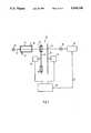
- FIG. 1is a schematic illustration of a mulitcomponent photometer.
- FIG. 2is a side view of a constructive embodiment of a multicomponent photometer.
- FIG. 3shows, in detail, a side view of a filter wheel which carries the first and the second gas vessels.
- FIG. 4is a view of the filter wheel as seen from the right in FIG. 3.
- FIG. 5shows, in detail, a side view of a filter wheel which carries the blocking filters.
- FIG. 6is a view of the filter wheel of FIG. 5 as seen from the left in FIG. 3.
- numeral 10designates a light source which emits a spectral continuum.
- a measuring light beam 12originates from the light source 10.
- the measuring light beam 12passes through a sample vessel 14 through which a sample gas in the form of a gas mixture passes.
- the sample gasenters the sample vessel 14 through an inlet 16 and emerges from the sample vessel 14 through an outlet 18.
- Switching means 20are arranged behind the sample vessel 14, through which switching means 20 a measuring path of rays or a reference path of rays can be optionally created.
- the switching means 20comprise a first filter wheel 22 and a second filter wheel 24.
- a plurality of first gas vessels 26 and one or several second gas vessels 28are arranged as filters in the first filter wheel 22. Only one first and one second gas vessel threreof can be seen in the schematic illustration of FIG. 1.
- the filter wheel 22is arranged to be driven by a servomotor 30.
- Blocking filters 32are arranged in the second filter wheel 24. These are filters which transmit only a limited wave length range of a continuum.
- the filter wheel 24is arranged to be driven by a servomotor 34.
- the two servomotorsare connected to a control device 36.
- Each of the first gas vessels 26is filled by a gas looked for and to be determined in the sample gas.
- a second gas vessel 28is associated with the first gas vessel 26, which second gas vessel 28 is filled with a reference gas which does not contain the gas looked for and therefore does not absorb in the region of the used absorption band of the gas looked for.
- a single blocking filter 32is associated with each pair of first and second gas vessels 26 and 28.
- the blocking filter 32can be an interference filter. Of the continuum emitted from the light source 10, the blocking filter transmits only a relatively narrow wave range about the used absorption band of the gas looked for.
- the measuring light beam 12falls on a detector 36 which supplies a signal according to the intensity of the measuring light beam 12.
- This signalis applied to a signal processing circuit 38.
- the signal processing circuit 38receives signals from the control device 36 through the signal path 40, which signals indicate which gas vessel at the moment is located in the path of rays of the measuring light beam. From the measuring values obtained for a certain gas with the measuring path of rays and with the reference path of rays, the signal processing circuit provides a measuring value for the concentration or the partial pressure of the concerned gas in the sample.
- the control device 36controls the filter wheels 22 and 24 through the servomotors 30 and 34 such that one and the same blocking filter 32 is located in the path of rays of the measuring light beam 12 when interposing the first gas vessel 26 of a certain gas and when interposing the associated second gas vessel 28.
- the sample vessel 14is attached to a partition 46 through bolts 42 and spacers 44.
- the measuring light beam 12passes through a window 48.
- a tube 50is attached to the sample vessel 14 and extends through an aperture 52 of the partition 46.
- the measuring light beam 12extends along the axis of the tube 50.
- a second partition 54is arranged parallel to and spaced from the partition 46.
- a tube 58is located in an aperture 56 of the partition 54.
- the tube 58is screwed to the partition 54 through bolts 60.
- the tube 58is coaxial with the tube 50.
- a lens 62is located in the tube 58.
- the servomotor 30is attached with an axle 66 to the partition 54.
- a filter wheel 22is located on the axle 66.
- the filter wheelcarries gas vessels of which one gas vessel 26 can be seen in FIG. 2.
- the gas vessel 26has a hollow cylindrical mounting 68 in which two parallel windows 70 and 72 are cemented.
- a filling socket 74is attached to the mounting 68. After a gas has been filled the filling socket 74 is closed at the tip, e.g. by smelting.
- a gasis filled in the gas vessel 26, the concentration of which gas in a sample gas shall be determined.
- a reference gasis filled in a similarly constructed gas vessel 28, which reference gas does not absorb in the region of the absorption band of the gas of the gas vessel 26.
- the gas vessel 26is located with its mounting in an aperture 76 of the filter wheel 22 and is attached with screw bolts 78. In the illustrated position of the filter wheel 22 the gas vessel 26 is aligned with the tube 58.
- the measuring light beam 12passes through the tube 50, the lens 62 and the tube 58 and through the gas vessel 26.
- a light barrier 80is attached to the partition 54.
- a flag 82extends into the light barrier 80, which flag 82 is screwed onto the filter wheel 22. In this way a defined reference position of the filter wheel 22 is obtained, to which position the other positions to be adjusted by the servomotor 30 can be referred.
- a further lens 86is located in a third partition 84 in a mounting 88.
- the mounting 88is located in an aperture 90 of the partition 84 and is connected to the partition 84 through screws 92.
- a fourth partition 94carries a housing 96 with the detector 36.
- the housing 96is closed by a window 98.
- the housing 96is located in an aperture 100 of the partition 94.
- a cap 101covers printed cards and electrical components for processing the signal from the detector 36.
- the servomotor 34is located on the partition 94 on its side remote from the partition 84.
- the servomotor 34is centered in an aperture 102 of the partition 94 and is connected to the partition 94 through screws 104.
- the filter wheel 24is located on a shaft 106 of the servomotor 34.
- the filter wheel 24carries the blocking filters 32 in the form of interference filters, which are each held in a mounting 108.
- the mounting 108 of each blocking filter 32is located in an aperture 110 of the filter wheel 24 and is connected to the filter wheel 24 through screws 112.
- a light barrier 116 at the partition 94supplies a reference position for the filter wheel 24 (FIG. 6).
- the light barrier 116is constructed in a manner similar to the light barrier 80 (FIG. 2)
- gas vessels 26 and 28are located beside each other in the filter wheel 22. Only two gas vessels are illustrated in FIG. 4.
- balance weights 114are attached on the opposite sides, of which balance weights only one is drafted.
- Each balance weightconsists of several discs placed upon each other and attached by screws 118 (FIG. 3).
- several gas vessels 26 and 28can be inserted into the apertures 76 of the filter wheel 22 for determining several components of the sample gas.
- more than one first gas vessel 26can be associated with a second gas vessel 28.
Landscapes
- Physics & Mathematics (AREA)
- Spectroscopy & Molecular Physics (AREA)
- Health & Medical Sciences (AREA)
- Life Sciences & Earth Sciences (AREA)
- Chemical & Material Sciences (AREA)
- Analytical Chemistry (AREA)
- Biochemistry (AREA)
- General Health & Medical Sciences (AREA)
- General Physics & Mathematics (AREA)
- Immunology (AREA)
- Pathology (AREA)
- Investigating Or Analysing Materials By Optical Means (AREA)
Abstract
Description
Claims (1)
Priority Applications (1)
| Application Number | Priority Date | Filing Date | Title |
|---|---|---|---|
| US07/374,439US5036198A (en) | 1989-06-30 | 1989-06-30 | Multicomponent photometer |
Applications Claiming Priority (1)
| Application Number | Priority Date | Filing Date | Title |
|---|---|---|---|
| US07/374,439US5036198A (en) | 1989-06-30 | 1989-06-30 | Multicomponent photometer |
Publications (1)
| Publication Number | Publication Date |
|---|---|
| US5036198Atrue US5036198A (en) | 1991-07-30 |
Family
ID=23476823
Family Applications (1)
| Application Number | Title | Priority Date | Filing Date |
|---|---|---|---|
| US07/374,439Expired - LifetimeUS5036198A (en) | 1989-06-30 | 1989-06-30 | Multicomponent photometer |
Country Status (1)
| Country | Link |
|---|---|
| US (1) | US5036198A (en) |
Cited By (27)
| Publication number | Priority date | Publication date | Assignee | Title |
|---|---|---|---|---|
| US5519219A (en)* | 1994-09-08 | 1996-05-21 | Janos Technology Inc. | Portable filter infrared spectrometer |
| US5559333A (en)* | 1993-11-29 | 1996-09-24 | Shimadzu Corporation | Apparatus of non-dispersive infrared analyzer |
| US5585635A (en)* | 1994-09-26 | 1996-12-17 | Marquette Electronics, Inc. | Infrared gas analyzer and method |
| GB2314411A (en)* | 1996-06-21 | 1997-12-24 | Graviner Ltd Kidde | Filter wheel for use in a gas filter correlation system |
| US5900635A (en)* | 1995-09-29 | 1999-05-04 | Instrumentarium Oy | Correction of collision broadening in non-dispersive absorption measurement of gases |
| US6007777A (en)* | 1996-11-18 | 1999-12-28 | Tekmar Company | Liquid sample carbon analyzer |
| USD421653S (en)* | 1996-11-18 | 2000-03-14 | Tekmar Company | Housing for a laboratory instrument |
| US6147351A (en)* | 1996-12-30 | 2000-11-14 | Instrumentarium Corp. | Accurate measurement for the concentration of a gas component in a gas mixture, wherein other components influence the concentration analysis |
| US20030072680A1 (en)* | 2001-09-20 | 2003-04-17 | Yasuhiro Higuchi | Colorimetric absorbance measurement apparatus |
| US20030086073A1 (en)* | 2001-11-08 | 2003-05-08 | Braig James R. | Reagent-less whole-blood glucose meter |
| US20030086075A1 (en)* | 2001-11-08 | 2003-05-08 | Braig James R. | Device and method for in vitro determination of analyte concentrations within body fluids |
| US20030086074A1 (en)* | 2001-11-08 | 2003-05-08 | Braig James R. | Device and method for in vitro determination of analyte concentrations within body fluids |
| US20030090649A1 (en)* | 2001-11-08 | 2003-05-15 | Sterling Bernhard B. | Reagent-less whole-blood glucose meter |
| US20050106749A1 (en)* | 2003-04-15 | 2005-05-19 | Braig James R. | Sample element for use in material analysis |
| WO2006085646A1 (en)* | 2005-02-14 | 2006-08-17 | Japan Science And Technology Agency | Apparatus for gas concentration measuring according to gas correlation method |
| KR100871909B1 (en)* | 2007-06-15 | 2008-12-05 | 한국표준과학연구원 | Infrared gas detector with optional detector module |
| US20090326343A1 (en)* | 2005-02-14 | 2009-12-31 | Optiscan Biomedical Corporation | Fluid handling cassette having a spectroscopic sample cell |
| US8379208B1 (en)* | 2010-06-09 | 2013-02-19 | Exelis, Inc. | System and method for passive remote detection of gas plumes |
| US20130265578A1 (en)* | 2012-04-10 | 2013-10-10 | G & A Technical Software, Inc. | Independent-beam gas filter correlation radiometry with field-of-view matching |
| US8928877B2 (en) | 2011-07-06 | 2015-01-06 | Optiscan Biomedical Corporation | Sample cell for fluid analysis system |
| US9091676B2 (en) | 2010-06-09 | 2015-07-28 | Optiscan Biomedical Corp. | Systems and methods for measuring multiple analytes in a sample |
| CN104865227A (en)* | 2015-03-30 | 2015-08-26 | 天津大学 | Quantitative measurement apparatus for volume fraction of soot produced by combustion in optical engine cylinder |
| US9554742B2 (en) | 2009-07-20 | 2017-01-31 | Optiscan Biomedical Corporation | Fluid analysis system |
| US9883830B2 (en) | 2005-10-06 | 2018-02-06 | Optiscan Biomedical Corporation | Fluid handling cassette system for body fluid analyzer |
| CN104833665B (en)* | 2015-03-30 | 2018-08-24 | 天津大学 | Multicomponent simultaneous measuring apparatus during a kind of optical engine in-cylinder combustion |
| US10201303B2 (en) | 2009-07-20 | 2019-02-12 | Optiscan Biomedical Corporation | Fluid analysis system |
| WO2024014874A1 (en)* | 2022-07-14 | 2024-01-18 | 한국원자력연구원 | Isotope ratio measuring device using isotope notch filter |
Citations (7)
| Publication number | Priority date | Publication date | Assignee | Title |
|---|---|---|---|---|
| US2926253A (en)* | 1954-12-22 | 1960-02-23 | Distillers Co Yeast Ltd | Radiation analysis |
| US3860344A (en)* | 1973-05-10 | 1975-01-14 | Honeywell Inc | Multi-component infrared analyzer |
| US3869613A (en)* | 1972-02-01 | 1975-03-04 | Akron Scient Labs | Infrared gas analyzers |
| US3968367A (en)* | 1974-09-16 | 1976-07-06 | Honeywell Inc. | Filter system for infrared analysis |
| US4445359A (en)* | 1981-08-07 | 1984-05-01 | Measurex Corporation | System and process for calibrating a combustion gas analyzer |
| US4641973A (en)* | 1981-09-22 | 1987-02-10 | H. Maihak Ag | Method and apparatus for measurement of the concentration of a component of a mixture |
| US4678914A (en)* | 1984-04-30 | 1987-07-07 | Environmental Tectonics Corporation | Digital IR gas analyzer |
- 1989
- 1989-06-30USUS07/374,439patent/US5036198A/ennot_activeExpired - Lifetime
Patent Citations (7)
| Publication number | Priority date | Publication date | Assignee | Title |
|---|---|---|---|---|
| US2926253A (en)* | 1954-12-22 | 1960-02-23 | Distillers Co Yeast Ltd | Radiation analysis |
| US3869613A (en)* | 1972-02-01 | 1975-03-04 | Akron Scient Labs | Infrared gas analyzers |
| US3860344A (en)* | 1973-05-10 | 1975-01-14 | Honeywell Inc | Multi-component infrared analyzer |
| US3968367A (en)* | 1974-09-16 | 1976-07-06 | Honeywell Inc. | Filter system for infrared analysis |
| US4445359A (en)* | 1981-08-07 | 1984-05-01 | Measurex Corporation | System and process for calibrating a combustion gas analyzer |
| US4641973A (en)* | 1981-09-22 | 1987-02-10 | H. Maihak Ag | Method and apparatus for measurement of the concentration of a component of a mixture |
| US4678914A (en)* | 1984-04-30 | 1987-07-07 | Environmental Tectonics Corporation | Digital IR gas analyzer |
Cited By (56)
| Publication number | Priority date | Publication date | Assignee | Title |
|---|---|---|---|---|
| US5559333A (en)* | 1993-11-29 | 1996-09-24 | Shimadzu Corporation | Apparatus of non-dispersive infrared analyzer |
| US5519219A (en)* | 1994-09-08 | 1996-05-21 | Janos Technology Inc. | Portable filter infrared spectrometer |
| US5585635A (en)* | 1994-09-26 | 1996-12-17 | Marquette Electronics, Inc. | Infrared gas analyzer and method |
| US5900635A (en)* | 1995-09-29 | 1999-05-04 | Instrumentarium Oy | Correction of collision broadening in non-dispersive absorption measurement of gases |
| GB2314411A (en)* | 1996-06-21 | 1997-12-24 | Graviner Ltd Kidde | Filter wheel for use in a gas filter correlation system |
| US6007777A (en)* | 1996-11-18 | 1999-12-28 | Tekmar Company | Liquid sample carbon analyzer |
| USD421653S (en)* | 1996-11-18 | 2000-03-14 | Tekmar Company | Housing for a laboratory instrument |
| US6147351A (en)* | 1996-12-30 | 2000-11-14 | Instrumentarium Corp. | Accurate measurement for the concentration of a gas component in a gas mixture, wherein other components influence the concentration analysis |
| US20030072680A1 (en)* | 2001-09-20 | 2003-04-17 | Yasuhiro Higuchi | Colorimetric absorbance measurement apparatus |
| GB2384853A (en)* | 2001-09-20 | 2003-08-06 | Furuno Electric Co | Colorimetric absorbance measurement apparatus |
| US7910061B2 (en) | 2001-09-20 | 2011-03-22 | Furuno Electric Company, Limited | Colorimetric absorbance measurement apparatus |
| CN100390527C (en)* | 2001-09-20 | 2008-05-28 | 古野电气株式会社 | Colorimetric extinction measuring device |
| GB2384853B (en)* | 2001-09-20 | 2005-11-02 | Furuno Electric Co | Colorimetric absorbance measurement apparatus |
| US20060268258A1 (en)* | 2001-11-08 | 2006-11-30 | Braig James R | Device and method for in vitro determination of analyte concentrations within body fluids |
| US20030086074A1 (en)* | 2001-11-08 | 2003-05-08 | Braig James R. | Device and method for in vitro determination of analyte concentrations within body fluids |
| US6958809B2 (en) | 2001-11-08 | 2005-10-25 | Optiscan Biomedical Corporation | Reagent-less whole-blood glucose meter |
| US20030090649A1 (en)* | 2001-11-08 | 2003-05-15 | Sterling Bernhard B. | Reagent-less whole-blood glucose meter |
| US6989891B2 (en) | 2001-11-08 | 2006-01-24 | Optiscan Biomedical Corporation | Device and method for in vitro determination of analyte concentrations within body fluids |
| US7050157B2 (en) | 2001-11-08 | 2006-05-23 | Optiscan Biomedical Corp. | Reagent-less whole-blood glucose meter |
| US7061593B2 (en) | 2001-11-08 | 2006-06-13 | Optiscan Biomedical Corp. | Device and method for in vitro determination of analyte concentrations within body fluids |
| US9907504B2 (en) | 2001-11-08 | 2018-03-06 | Optiscan Biomedical Corporation | Analyte monitoring systems and methods |
| US7738085B2 (en) | 2001-11-08 | 2010-06-15 | Optiscan Biomedical Corporation | Device and method for in vitro determination of analyte concentration within body fluids |
| US7872734B2 (en) | 2001-11-08 | 2011-01-18 | Optiscan Biomedical Corporation | In vitro determination of analyte levels within body fluids |
| US9404852B2 (en) | 2001-11-08 | 2016-08-02 | Optiscan Biomedical Corporation | Analyte monitoring systems and methods |
| US7999927B2 (en) | 2001-11-08 | 2011-08-16 | Optiscan Biomedical Corporation | In vitro determination of analyte levels within body fluids |
| US7480032B2 (en) | 2001-11-08 | 2009-01-20 | Optiscan Biomedical Corporation | Device and method for in vitro determination of analyte concentrations within body fluids |
| US20030086075A1 (en)* | 2001-11-08 | 2003-05-08 | Braig James R. | Device and method for in vitro determination of analyte concentrations within body fluids |
| US20090213360A1 (en)* | 2001-11-08 | 2009-08-27 | Optiscan Biomedical Corporation | Device and method for in vitro determination of analyte concentration within body fluids |
| US20030086073A1 (en)* | 2001-11-08 | 2003-05-08 | Braig James R. | Reagent-less whole-blood glucose meter |
| US20050106749A1 (en)* | 2003-04-15 | 2005-05-19 | Braig James R. | Sample element for use in material analysis |
| US20090326343A1 (en)* | 2005-02-14 | 2009-12-31 | Optiscan Biomedical Corporation | Fluid handling cassette having a spectroscopic sample cell |
| JP4552217B2 (en)* | 2005-02-14 | 2010-09-29 | 独立行政法人科学技術振興機構 | Gas concentration measuring device by gas correlation method |
| US7655910B2 (en) | 2005-02-14 | 2010-02-02 | Japan Science And Technology Agency | Apparatus for gas concentration measurement according to gas correlation method |
| US20090026374A1 (en)* | 2005-02-14 | 2009-01-29 | Yoshizumi Kajii | Apparatus for gas concentration measurement according to gas correlation method |
| US8197770B2 (en) | 2005-02-14 | 2012-06-12 | Optiscan Biomedical Corporation | Fluid handling cassette having a spectroscopic sample cell |
| US10568556B2 (en) | 2005-02-14 | 2020-02-25 | Optiscan Biomedical Corporation | Bodily fluid composition analyzer with disposable cassette |
| US10568555B2 (en) | 2005-02-14 | 2020-02-25 | Optiscan Biomedical Corporation | Fluid handling cassette |
| WO2006085646A1 (en)* | 2005-02-14 | 2006-08-17 | Japan Science And Technology Agency | Apparatus for gas concentration measuring according to gas correlation method |
| US9883829B2 (en) | 2005-02-14 | 2018-02-06 | Optiscan Biomedical Corporation | Bodily fluid composition analyzer with disposable cassette |
| JPWO2006085646A1 (en)* | 2005-02-14 | 2008-06-26 | 独立行政法人科学技術振興機構 | Gas concentration measuring device by gas correlation method |
| US10383561B2 (en) | 2005-10-06 | 2019-08-20 | Optiscan Biomedical Corporation | Fluid handling cassette system for body fluid analyzer |
| US9883830B2 (en) | 2005-10-06 | 2018-02-06 | Optiscan Biomedical Corporation | Fluid handling cassette system for body fluid analyzer |
| KR100871909B1 (en)* | 2007-06-15 | 2008-12-05 | 한국표준과학연구원 | Infrared gas detector with optional detector module |
| US9554742B2 (en) | 2009-07-20 | 2017-01-31 | Optiscan Biomedical Corporation | Fluid analysis system |
| US10201303B2 (en) | 2009-07-20 | 2019-02-12 | Optiscan Biomedical Corporation | Fluid analysis system |
| US10660557B2 (en) | 2009-07-20 | 2020-05-26 | Optiscan Biomedical Corporation | Fluid analysis cuvette with coupled transparent windows |
| US9091676B2 (en) | 2010-06-09 | 2015-07-28 | Optiscan Biomedical Corp. | Systems and methods for measuring multiple analytes in a sample |
| US8379208B1 (en)* | 2010-06-09 | 2013-02-19 | Exelis, Inc. | System and method for passive remote detection of gas plumes |
| US8928877B2 (en) | 2011-07-06 | 2015-01-06 | Optiscan Biomedical Corporation | Sample cell for fluid analysis system |
| US8681337B2 (en)* | 2012-04-10 | 2014-03-25 | G & A Technical Software, Inc. | Independent-beam gas filter correlation radiometry with field-of-view matching |
| US20130265578A1 (en)* | 2012-04-10 | 2013-10-10 | G & A Technical Software, Inc. | Independent-beam gas filter correlation radiometry with field-of-view matching |
| CN104865227A (en)* | 2015-03-30 | 2015-08-26 | 天津大学 | Quantitative measurement apparatus for volume fraction of soot produced by combustion in optical engine cylinder |
| CN104833665B (en)* | 2015-03-30 | 2018-08-24 | 天津大学 | Multicomponent simultaneous measuring apparatus during a kind of optical engine in-cylinder combustion |
| WO2024014874A1 (en)* | 2022-07-14 | 2024-01-18 | 한국원자력연구원 | Isotope ratio measuring device using isotope notch filter |
| KR20240009760A (en)* | 2022-07-14 | 2024-01-23 | 한국원자력연구원 | isotope ratio measuring device using isotope notch filter |
| KR102748087B1 (en) | 2022-07-14 | 2024-12-31 | 한국원자력연구원 | isotope ratio measuring device using isotope notch filter |
Similar Documents
| Publication | Publication Date | Title |
|---|---|---|
| US5036198A (en) | Multicomponent photometer | |
| US2439373A (en) | Flickering beam photometer | |
| DE3479531D1 (en) | An infrared absorption gas detector | |
| US4781456A (en) | Absorption photometer | |
| DE102009025147B3 (en) | Method for operating a spectrometer for gas analysis, and spectrometer itself | |
| DE2526794A1 (en) | GAS ANALYZER | |
| CA2053398A1 (en) | Optical analytical instrument and method | |
| EP0145877B1 (en) | Photometer for continuous analysis of a medium (gas or liquid) | |
| US4591721A (en) | Oxygen analysis employing absorption spectroscopy | |
| EP0349839B1 (en) | Multicomponent photometer | |
| US2926253A (en) | Radiation analysis | |
| US4822168A (en) | Spectroscopic photometer for flow through sample absorption | |
| US6661011B2 (en) | Multi-component gas analyzer having cassette-type light path system | |
| US4487477A (en) | Optical beam splitter | |
| US3901601A (en) | Chopper arrangement for atomic absorption spectrophotometer | |
| US4867562A (en) | Atomic absorption spectrophotometer | |
| US5977546A (en) | Self normalizing radiant energy monitor and apparatus for gain independent material quantity measurements | |
| DE2136634A1 (en) | Optical arrangement for a device for analyzing a sample by atomic spectroscopy | |
| IE53138B1 (en) | Optical beam splitter | |
| WO1985003575A1 (en) | Optical analysis instrument having rotating optical standards | |
| US4504145A (en) | Apparatus capable of measurement of profile of emission line spectrum | |
| Hyvarinen et al. | Rugged multiwavelength NIR and IR analyzers for industrial process measurements | |
| US4210808A (en) | Pneumatic infrared analyzer of the single beam type | |
| GB899973A (en) | Radiation fluid analyser | |
| EP0062478A3 (en) | Spectrochemical analyzer |
Legal Events
| Date | Code | Title | Description |
|---|---|---|---|
| AS | Assignment | Owner name:BODENSEEWERK GERATETECHNIK GMBH,, GERMANY Free format text:ASSIGNMENT OF ASSIGNORS INTEREST.;ASSIGNOR:SPAETH, TILMANN;REEL/FRAME:005132/0419 Effective date:19891207 | |
| AS | Assignment | Owner name:BODENSEEWERK PERKIN-ELMER GMBH (BSW), A CORP. OF T Free format text:ASSIGNMENT OF ASSIGNORS INTEREST.;ASSIGNOR:BODENSEEWERK GERATETECHNIK GMBH;REEL/FRAME:005199/0897 Effective date:19891108 | |
| STCF | Information on status: patent grant | Free format text:PATENTED CASE | |
| FEPP | Fee payment procedure | Free format text:PAYOR NUMBER ASSIGNED (ORIGINAL EVENT CODE: ASPN); ENTITY STATUS OF PATENT OWNER: LARGE ENTITY Free format text:PAT HLDR NO LONGER CLAIMS SMALL ENT STAT AS INDIV INVENTOR (ORIGINAL EVENT CODE: LSM1); ENTITY STATUS OF PATENT OWNER: LARGE ENTITY | |
| FPAY | Fee payment | Year of fee payment:4 | |
| FPAY | Fee payment | Year of fee payment:8 | |
| REMI | Maintenance fee reminder mailed | ||
| AS | Assignment | Owner name:SICK UPA GMBH, GERMANY Free format text:ASSIGNMENT OF ASSIGNORS INTEREST;ASSIGNOR:BODENSEEWERK PERK IN-ELMER GMBH;REEL/FRAME:010351/0661 Effective date:19990927 | |
| AS | Assignment | Owner name:BERTHOLD GMBH & CO. KG, GERMANY Free format text:ASSIGNMENT OF ASSIGNORS INTEREST;ASSIGNOR:PERKIN ELMER BODENSEEWERK GMBH;REEL/FRAME:013456/0614 Effective date:20010328 | |
| FPAY | Fee payment | Year of fee payment:12 |