US5034967A - Metastable-free digital synchronizer with low phase error - Google Patents
Metastable-free digital synchronizer with low phase errorDownload PDFInfo
- Publication number
- US5034967A US5034967AUS07/285,206US28520688AUS5034967AUS 5034967 AUS5034967 AUS 5034967AUS 28520688 AUS28520688 AUS 28520688AUS 5034967 AUS5034967 AUS 5034967A
- Authority
- US
- United States
- Prior art keywords
- clock signal
- signal
- phase
- synchronizer
- phase shifted
- Prior art date
- Legal status (The legal status is an assumption and is not a legal conclusion. Google has not performed a legal analysis and makes no representation as to the accuracy of the status listed.)
- Expired - Fee Related
Links
- 230000007704transitionEffects0.000claimsabstractdescription50
- 230000004044responseEffects0.000claimsdescription22
- 230000000630rising effectEffects0.000claimsdescription22
- 230000000737periodic effectEffects0.000claimsdescription8
- 230000000977initiatory effectEffects0.000claims6
- 230000001360synchronised effectEffects0.000abstractdescription75
- 230000001934delayEffects0.000description17
- 238000004891communicationMethods0.000description9
- 238000010586diagramMethods0.000description9
- 230000006870functionEffects0.000description8
- 238000005070samplingMethods0.000description7
- 238000013459approachMethods0.000description4
- 230000000694effectsEffects0.000description4
- 230000005540biological transmissionEffects0.000description3
- 230000001419dependent effectEffects0.000description3
- 230000009977dual effectEffects0.000description3
- 238000000034methodMethods0.000description3
- 238000011084recoveryMethods0.000description3
- 230000003213activating effectEffects0.000description2
- 230000008901benefitEffects0.000description2
- 239000013078crystalSubstances0.000description2
- 238000013461designMethods0.000description2
- 238000004519manufacturing processMethods0.000description2
- 230000003252repetitive effectEffects0.000description2
- 230000001960triggered effectEffects0.000description2
- DNTFEAHNXKUSKQ-RFZPGFLSSA-N(1r,2r)-2-aminocyclopentane-1-sulfonic acidChemical compoundN[C@@H]1CCC[C@H]1S(O)(=O)=ODNTFEAHNXKUSKQ-RFZPGFLSSA-N0.000description1
- XUIMIQQOPSSXEZ-UHFFFAOYSA-NSiliconChemical compound[Si]XUIMIQQOPSSXEZ-UHFFFAOYSA-N0.000description1
- 230000009471actionEffects0.000description1
- 230000002411adverseEffects0.000description1
- 238000004458analytical methodMethods0.000description1
- 238000001514detection methodMethods0.000description1
- 238000006073displacement reactionMethods0.000description1
- 238000005516engineering processMethods0.000description1
- 239000000835fiberSubstances0.000description1
- 230000003287optical effectEffects0.000description1
- 230000010363phase shiftEffects0.000description1
- 230000002035prolonged effectEffects0.000description1
- 229910052710siliconInorganic materials0.000description1
- 239000010703siliconSubstances0.000description1
- 238000012546transferMethods0.000description1
- 238000009966trimmingMethods0.000description1
Images


Classifications
- H—ELECTRICITY
- H04—ELECTRIC COMMUNICATION TECHNIQUE
- H04L—TRANSMISSION OF DIGITAL INFORMATION, e.g. TELEGRAPHIC COMMUNICATION
- H04L7/00—Arrangements for synchronising receiver with transmitter
- H04L7/02—Speed or phase control by the received code signals, the signals containing no special synchronisation information
- H04L7/033—Speed or phase control by the received code signals, the signals containing no special synchronisation information using the transitions of the received signal to control the phase of the synchronising-signal-generating means, e.g. using a phase-locked loop
- H04L7/0337—Selecting between two or more discretely delayed clocks or selecting between two or more discretely delayed received code signals
- H04L7/0338—Selecting between two or more discretely delayed clocks or selecting between two or more discretely delayed received code signals the correction of the phase error being performed by a feed forward loop
- H—ELECTRICITY
- H04—ELECTRIC COMMUNICATION TECHNIQUE
- H04L—TRANSMISSION OF DIGITAL INFORMATION, e.g. TELEGRAPHIC COMMUNICATION
- H04L25/00—Baseband systems
- H04L25/02—Details ; arrangements for supplying electrical power along data transmission lines
- H04L25/03—Shaping networks in transmitter or receiver, e.g. adaptive shaping networks
- H04L25/03006—Arrangements for removing intersymbol interference
- H—ELECTRICITY
- H04—ELECTRIC COMMUNICATION TECHNIQUE
- H04L—TRANSMISSION OF DIGITAL INFORMATION, e.g. TELEGRAPHIC COMMUNICATION
- H04L25/00—Baseband systems
- H04L25/38—Synchronous or start-stop systems, e.g. for Baudot code
- H04L25/40—Transmitting circuits; Receiving circuits
- H04L25/49—Transmitting circuits; Receiving circuits using code conversion at the transmitter; using predistortion; using insertion of idle bits for obtaining a desired frequency spectrum; using three or more amplitude levels ; Baseband coding techniques specific to data transmission systems
- H04L25/4917—Transmitting circuits; Receiving circuits using code conversion at the transmitter; using predistortion; using insertion of idle bits for obtaining a desired frequency spectrum; using three or more amplitude levels ; Baseband coding techniques specific to data transmission systems using multilevel codes
- H04L25/4919—Transmitting circuits; Receiving circuits using code conversion at the transmitter; using predistortion; using insertion of idle bits for obtaining a desired frequency spectrum; using three or more amplitude levels ; Baseband coding techniques specific to data transmission systems using multilevel codes using balanced multilevel codes
Definitions
- the present inventionrelates to synchronizers, and more particularly to a new and improved technique, capable of all-digital implementation, of rapidly synchronizing a clock signal with an asynchronous event defined by a signal transition (e.g. edge) of an external asynchronous signal.
- a signal transitione.g. edge
- Synchronizersfind widespread applicability in a variety of interface environments where complete time base synchronization cannot be maintained throughout the whole system.
- a typical exampleis in a computer system which must receive a data stream of known frequency from an external device which operates from its own, independent timebase
- an I/O interface of the computer systemmust be able to sample the incoming signals in phase with the signal transitions generated by the external device.
- Properly sampling the signalsrequires that the I/O interface synchronize a sampling clock signal to be in phase with the received data stream for the duration of the transmission from the external device to the I/O interface.
- I/O interfaceswhich usually employ clock synchronizers include magnetic media read channels (disk drives, diskette drives, tape drives, etc.), local area network receivers, wide area network serial receivers including satellite and microwave communication links and broadband and fiber optic cable links, and mechanical scanner interfaces (card readers, bar code readers, badge readers, optical recognition scanners, etc.).
- clock synchronizersare called "clock recovery circuits".
- data separatorsIn magnetic media read channels, the circuits referred to as “data separators" generally include a clock synchronizer.
- Clock synchronizersare needed in physically distributed synchronized communication systems, such as synchronous modems communicating over a telephone network or token ring local area networks. In such physically distributed environments it is not possible to use a physically common clock among all points and components of the communication system.
- the transmitters and receiversare maintained in synchronism by signals communicated over the communication medium.
- the traditional techniques for implementing this synchronizationinvolve using phase-locked loops, self-clocking codes, and/or resynchable oscillators.
- Phase-locked loopsrecover the transmission clock signal from the received data stream.
- phase-locked loop synchronizersrequire a number of cycles of the received signal before the proper frequency and phase characteristics can be established.
- a somewhat lengthy preamblemust be inserted at the beginning of each data block or signal stream, in order to supply the necessary signals to achieve synchronization before the presentation of the data. Since the preamble does not contain useful data, the time required to transfer the preamble reduces the efficiency of communication.
- An example of this situationis a well known local area network, which uses a phase-locked loop for clock recovery and requires a 64-bit preamble at the beginning of every frame of data communicated in order to establish synchronization.
- phase-locked loopThe fundamental characteristic of a phase-locked loop is that it can be optimized for capture range, that is, the amount of error in the input frequency which can be tolerated, or it can be optimized for phase accuracy, but it cannot be optimized for both simultaneously.
- capture rangethat is, the amount of error in the input frequency which can be tolerated
- phase accuracybut it cannot be optimized for both simultaneously.
- a direct and unavoidable side effect of using a phase-locked loopis the need for the relatively lengthy preamble and/or some means to limit the possible input frequency variation.
- rapid synchronization or loop lock-onis required, extreme accuracy cannot be achieved
- most synchronizers employing phase-locked loopsrequire calibration, at least during manufacture and often during use, due to the use of tuned analog components in the phase locked loop.
- Digital phase-locked loopsare known, but digital phase locked loops generally require reference clocks of many times the frequency of the signal stream in order to work effectively. High speed reference clocks can make synchronizers using digital phase locked loops prohibitively expensive for data communication rates over approximately 1 MHz.
- an oscillatorIn resynchable oscillator systems, an oscillator is started in phase with the beginning of an incoming signal stream. It is expected that the oscillator starts at a selected point with, and remains in phase while, the incoming signal stream is received. The oscillator is then resynchronized for each subsequent signal stream or data block. In cases where accurate timing tolerances are not required this approach is acceptable, but the cost, manufacturability difficulties, and limited accuracy of this approach makes it undesirable when high data rates, or high clock accuracy, are required. Because stable frequency reference clocks, such as crystal oscillator circuits, cannot be arbitrarily resynchronized, resynchable oscillators cannot employ a stable frequency reference. As a result, the fundamental output frequency of a resynchable oscillator tends to drift as a result of variations in temperature and voltage, which requires periodic recalibration during system operation.
- a form of a synchronizeris also employed in systems where it is desired to derive a synchronized clock output signal from an asynchronous event signal, but it is unnecessary or not required to establish or preserve the relative phase information between the synchronized clock output signal and the asynchronous event signal.
- the primary application for such a synchronizeris to eliminate the possibility of creating a metastable condition in the sampled output signal employed by the synchronous system and thereby avoid a situation where data sampling will be unreliable due to the metastability.
- Dual rank flip-flop synchronizersare typically used to avoid metastability when it is unnecessary to preserve the phase accuracy. Dual rank flip-flop synchronizers suffer from a number of disadvantages, in addition to the inability to preserve the phase accuracy or information.
- the output signal from a dual rank synchronizeris available only after a time period greater than one clock period has transpired after the asynchronous event. Actually, the availability of the output signal is within a variable, non-deterministic delay period, which ranges from one clock period plus the setup time of a flip-flop to two clock periods This variable, non-deterministic delay range depends on the relative phase of the clock signal and the asynchronous event signal.
- the present inventionoffers a new and improved alternative which overcomes many or all of the disadvantages associated with previously known synchronizers.
- the synchronizationtakes place in a manner that the synchronized clock output signal is in phase with the external asynchronous event signal, within a narrow, deterministic range of possible phase error; is a phase-shifted copy of or division of an internal stable frequency reference clock signal; is generated without the risk of synchronization failure due to a metastable condition; and is available a constant time delay after the asynchronous event signal.
- the delay from the activating event or edge of the asynchronous event signal to the delivery of the synchronized clock output signalis constant, is independent of the phase difference between the asynchronous input signal and the reference clock signal, and is not fixed by the period of the reference clock signal.
- the synchronized clock output signalis available in many cases after a delay time period of less than one reference clock period.
- the precision of the synchronized clock output signalis directly related to the accuracy of an internal stable frequency reference clock.
- the phase error of the synchronized clock output signal, relative to an external asynchronous input signal,is preferably determined by component delays, thereby avoiding calibration and trimming adjustments during manufacturing and use, which contributes to low cost and high reliability.
- the preferred form of the synchronizeris suitable for convenient, highly scalable, all-digital implementation within a single integrated circuit.
- the synchronizer of the present inventionsupplies a periodic output clock signal which is in synchronism with and phase shifted relative to a reference clock signal.
- the amount of the phase shiftis established by reference to the occurrence of an asynchronous signal.
- a plurality of phase shifted digital versions of the reference clock signalare created.
- the states of the plurality of phase shifted versions of the reference clock signalare sampled to logically define the one of the phase shifted versions which is to be utilized in deriving the synchronized output clock signal.
- the number of phase shifted versions of the reference clock signalis odd, and the time delay between each of these phase shifted versions is approximately equal, and the versions are spaced over the period of the reference clock signal.
- a registeris preferably utilized as a means for sampling and holding the state values of the plurality of phase shifted versions at the occurrence of the asynchronous signal. Metastability induced in the output signals from memory cells or flip-flops of the register is accounted for in decoding the states of the values set in the register to select the phase shifted version, by allowing the metastability event to settle or by use of logic which disregards the metastable signal or signals when selecting the one of the phase shifted versions from which the output clock signal is derived.
- the synchronized output clock signalis preferably available within one period of the reference clock signal, and after a fixed and predetermined time delay established by components within the synchronizer.
- the time delayis not influenced by the relative phase difference between the reference clock signal and the asynchronous event signal. Synchronization occurs more rapidly than with known synchronizers and the phase information can be preserved while rapidly synchronizing.
- the maximum phase erroris determinable from the number of phase shifted versions of the reference clock signal and from the period of the reference clock signal, and is not dependent upon the wide range of variables which typically influence prior synchronizers.
- synchronizationcan be advantageously established in response to a single transition of the asynchronous signal and within a time period typically less than the period of one reference clock signal, synchronization can be established much more rapidly with the present synchronizer than with known prior synchronizers. Rapid synchronization allows more efficient and effective data transmission in communication systems, as well as in other applications.
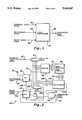
- FIG. 1is a generalized illustration of the clock synchronizer of the present invention. and the three major input signals to the clock synchronizer, a reference clock signal, a resync enable signal, and an asynchronous event signal; and the single output signal from the clock synchronizer, a synchronized clock signal.
- FIGS. 2A, 2B, 2C and 2Dare waveform diagrams of the reference clock signal, the resync enable signal, the asynchronous event signal and the synchronized clock signal, respectively, which are present in association with the clock synchronizer shown in FIG. 1.
- FIG. 3is a block diagram of one embodiment of the clock synchronizer shown in FIG. 1.
- FIG. 4is a diagram of logic components which illustrate the logical equations and functions of a phase logic selection circuit and a multiplexer circuit of the clock synchronizer shown in FIG. 3.
- FIG. 5is a block diagram of an alternative embodiment of the clock synchronizer shown in FIG. 1, wherein additional components are used in conjunction with the embodiment illustrated in FIG. 3.
- FIGS. 6A to 6Rare waveform diagrams illustrating examples of the waveforms of signals present in the embodiments of the clock synchronizer shown in FIGS. 3 and 5.
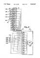
- FIG. 7is an illustration of the logic equations and logic components utilized in an embodiment of the phase selection logic and multiplexer circuit, which is an alternative to that shown in FIG. 4, either embodiment of which may be employed in the clock synchronizers shown in FIGS. 3 and 5.
- FIGS. 8A to 8BBare waveform diagrams illustrating the operation of the phase seleCtion logic and multiplexer circuit shown in FIG. 7.
- FIG. 9is a block diagram of a further alternative embodiment of the clock synchronizer shown in FIG. 1, used to achieve only metastable-free synchronization without preserving phase accuracy, and which is capable of synchronizing on the rising edge of an asynchronous event signal.
- FIG. 10is a block diagram of another alternative embodiment of the clock synchronizer shown in FIG. 9, which is capable of synchronizing on either the rising or falling edge of an asynchronous event signal.
- FIG. 11 and FIG. 12are logic diagrams of voter circuits employed in the embodiments of the clock synchronizers shown in FIGS. 9 and 10.
- a clock synchronizer 20 in FIG. 1The function of a clock synchronizer generally referenced 20 in FIG. 1, is to establish a temporary synchronized or predetermined phase and/or frequency relationship between a clocked, digital interface element (not shown) of which the synchronizer 20 is a part, and an external, independent-timebase, signal or data stream.
- the clock synchronizer 20is required because the incoming data stream is generated from a separate time base other than the clock of the receiving interface element, or because the incoming data stream has inexact or variable timing due to variations in the external communication medium and/or the transmitting device.
- the input signals to the synchronizer 20are a reference clock signal at 22 which is preferably a digital square wave oscillating at a reference frequency; an asynchronous event signal at 24, an edge or some other characteristic of which indicates the point in time for synchronization and which is created by or from the incoming data stream or other asynchronously received signal; and a resync enable signal at 26 which must be asserted for a transition of the asynchronous signal at 24 to cause the synchronizer 20 to resynchronize.
- the reference clock signal at 22can be supplied from an external stable frequency oscillator or from an internal stable frequency oscillator which is a part of the synchronizer 20. A stable frequency oscillator is not shown but its output signal, the reference clock signal 22, is shown.
- the output signal from the synchronizer 20is a synchronized clock signal at 28, which is a copy or division of the reference clock signal 22 and which is phase-shifted by the amount necessary to achieve a predetermined phase relationship between the asynchronous signal at 24 and synchronized clock signal at 28.
- Waveforms of the reference clock signal 22, the asynchronous signal 24, the resync enable signal 26, and the synchronized clock signal 28, supplied by an idealized clock synchronizer (one having no inherent component delays)are shown in FIGS. 2A, 2B, 2C and 2D, respectively.
- One typical synchronized phase relationship which can be produced by the clock synchronizer 20is the alignment of rising edges of the synchronized clock signal 28 with the rising edge of the asynchronous event signal 24, as is illustrated in FIGS. 2C and 2D.
- the reference clock signal 22is shown as a digitally oscillating symmetric square wave with a specific period 30.
- a well-known crystal oscillator of high accuracye.g. ⁇ 0.01% to ⁇ 0.001%
- the synchronized clock signal 28is in exact phase with the reference clock signal 22. Any phase relationship may actually exist between the reference clock signal 22 and the synchronized clock 28, and resynchronization will still be achieved as described below. Synchronization is not dependent on the range of any pre-existing phase relationship.
- Pulses 32, 34 and 36are shown as occuring as a part of the asynchronous signal 26.
- the separating intervals and the duty cycles of the pulses 32, 34 and 36,are not restrictive to the operation of the synchronizer 30, provided that a pulse has some minimum width which is defined by the logic implementation technology (and typically only a few nanoseconds).
- the asynchronous pulses 32 and 36do not affect the synchronized clock signal 28 because the pulses 32 and 36 occur when the resync enable signal 26 is negated.
- pulse 34 and the resync enable signal 26 during a resynchronization interval 38causes resynchronization to take place, as is illustrated by the connecting line 40.
- the assertion of resync enable signal 26forces the synchronized clock signal 28 to stay in a predetermined state (the low state is illustrated) during a blanking period 42 in order to prevent adverse spurious effects on the output synchronized clock signal 28 during resynchronization. This is illustrated by the arrow 44 and the absence of a rising edge of the synchronized clock signal 28 beginning at the time point designated 46 in FIGS. 2A to 2D and extending over the blanking period 42 to the time point 48.
- synchronizationis re-established as shown by the arrow 50 which indicates the occurrence of a rising transition of the synchronized clock signal 28.
- Resynchronizationoccurs at the time point 48, after the blanking period 42 and coincident with the rising edge of asynchronous signal pulse 34.
- the synchronized clock signal 28immediately resumes at point 48, while maintaining reference clock period 30.
- the synchronized clock signal 28is now in phase with the selected transition or leading edge of the pulse 34 of the asynchronous signal 26, and maintains this phase relationship, while oscillating at the frequency of the reference clock signal 22, until the next simultaneous assertion of a resync enable signal 26 and a pulse of the asynchronous signal 24.
- the resync enable signal 26is typically asserted in synchronism with a system clock signal (the reference clock signal 22 or a multiple thereof).
- the resync enable signal 26is shown asserted at an interval which is one-fourth the interval 30 of the reference clock signal 22, as is shown in FIGS. 2A and 2B, thereby illustrating a multiple of four situation.
- the negation of the resync enable signal 26typically occurs in direct response to the asynchronous transition which causes clock resynchronization, which is the pulse 34 in this example, as shown by arrow 52.
- the desired phase relationshipis the alignment of the rising edge of one cycle of the synchronized clock signal 28 with a rising edge or transition of the asynchronous signal 24.
- Any other specific characteristic of the asynchronous signal 24, such as a falling edge,can be employed to establish synchronization in a similar manner.
- One advantage of the present inventionis that this actual resynchronization delay is constant and short, in contrast to most prior clock synchronizers which deliver variable resynchronization delays or require resynchronization delays long enough to sample multiple transitions of the asynchronous signal. If a particular application requires a phase relationship other than the aligned-edge relationship described herein, upon clock resynchronization this other phase relationship can be achieved by changing the logical order of selection of the signal which is supplied as the synchronized clock signal 28, as can be better appreciated from the description below.
- the synchronizer 54 shown in FIG. 3receives the three input signals: the reference clock signal 22 (FIG. 6A); the asynchronous signal 24 (FIG. 6I), the leading edge or transition of which indicates the point 48 in time for synchronization to occur; and the resync enable signal 26 (FIG. 6G).
- the resync enable signal 26must be asserted for a transition of the asynchronous signal 24 to cause resynchronization.
- the output signal from the clock synchronizer 54is the synchronized clock signal 28 (FIG. 6R). For maximum efficiency the clock synchronizer is able to generate the appropriate synchronized clock signal 28 from a single transition of the asynchronous signal 26.
- the synchronizer 54includes a multi-tap delay line 90 with a total time delay no less than the period of the reference clock signal 22 and providing an odd number of taps for use (5 are illustrated); a pair of edge-triggered, D-type flip-flops 92 and 94; an edge-triggered register 96 with at least as many inputs and memory cell means or flip-flops as there are taps utilized on the delay line 90; a phase selection means or logic circuit 98 which determines and identifies the required phase for the synchronized clock signal 28 based on the code or set values of the register 96; a multiplexer 100 which passes the selected one of the signals available from the taps of the delay line 90 and inversions of those signals, under control of the phase selection logic circuit 98; a gate 102 to inhibit or "blank" the synchronized clock signal 28 while resynchronization is taking place; and a fixed delay line 104 which determines a fixed delay through the clock synchronizer 54.
- the delay 104may not be required and the delay through the circuit
- the delay line 90controls important aspects of the synchronizer's functionality.
- a series of phase-shifted copies or versions of the reference clock signalare available at the various taps.
- These phase shifted versions of the signal 22are collectively referenced 106 in FIG. 3 and are individually referenced 106A, 106B, 106C, 106D and 106E in FIGS. 6B, 6C, 6D, 6E and 6F, respectively.
- 106A, 106B, 106C, 106D and 106Ein FIGS. 6B, 6C, 6D, 6E and 6F, respectively.
- There are a wide variety of means to implement the delay function of the delay line 90some of which are discussed below.
- the delay line 90must provide a total delay at least as long as the period of the reference clock signal 22 (if longer, only the first "Nt" taps of the delay are used). An odd number of taps spread approximately evenly in time delay increments over the period of the reference clock signal 22 should be available. A minimum inter-tap delay spacing must exist which is greater than or equal to the setup time of the flip-flops in the register 96. Approximately uniform delays applied to both the rising and falling edges of the reference clock signal 22 must occur at each tap. Delay lines with these characteristics are readily available a printed circuit board mountable hybrid circuit modules from a number of manufacturers, such as Bel Fuse, Inc., Jersey City, N.J. (digital delay line series 0447), and Data Delay Devices Inc., Clifton, N.J. (active delay line DDU-xF series). For integrated circuit applications silicon delay lines can be fabricated, or strings of gates with predetermined minimum and maximum propagation delays can be used.
- the resync enable signal 26(FIG. 6G) which enables resynchronization is supplied to the flip-flop 94.
- the flip-flop 94sets (arrow 107, FIGS. 6H and 6R) and supplies an output signal 108 (FIG. 6H).
- the synchronized clock signal 28(FIG. 6R) is held in the low state (arrow 109, FIGS. 6H and 6R) due to the application of signal 110 from the flip-flop 94 to the AND gate 102 until resynchronization occurs. Setting the flip-flop 94 negates an overriding reset created by signal 108 normally supplied to flip-flop 92.
- flip-flop 94may be clocked by the resync enable signal 26 (with its D-input tied high), thereby eliminating the need to feed the synchronized clock signal 28 back to the clock terminal of flip-flop 94.
- the rising edge of the asynchronous signal 24sets flip-flop 92 after negation of the overriding reset (signal 108) to thereby initiate clock resynchronization (shown by an event line 48, FIGS. 6A to 6R).
- Flip-flop 92supplies an output signal 112 (FIG. 6J), which transitions from low to high immediately after the rising edge of the asynchronous signal 24.
- Flip-flop 92will not go into a metastable condition due to a setup time violation, because its D-input is connected to a high logic level signal 114.
- FIGS. 6C and 6LThe particular situation illustrated in FIGS. 6C and 6L is a case where the resynchronization event 48 created by the asynchronous signal 24 is very close in time to the transition of the phase shifted clock signal 106B, thereby causing a setup time violation 113 (FIG. 6C) at one flip-flop of the register 96.
- the setup time violationinduces a metastable condition 115 in the output signal 116B from this flip-flop of the register (FIG. 6L).
- the output signal levels 116A to 116E from the registercorrespond to the levels of the signals 106A to 106E at the resynchronization event 48.
- Signal 116Bmay settle in its previous state, which is acceptable since that state is indicative of a phase one earlier in the sequence and event 48 is within the phase error tolerance of that phase.
- the phase information 116 from the register 96(after metastable condition settling) is encoded by the phase selection logic circuit 98 to generate selection control signals 118.
- the selection control signals 118control the multiplexer 100 to select a single one of the phase-shifted clock signals 106, or an inverted version of one of these signals, and supply the selected signal at 106S.
- the multiplexer 100inverts the five phase shifted clock signals 28 (106A to 106E, FIG. 6B to 6F) to create five additional available signals, any one of the ten (5 normal and 5 inverted) of which becomes the signal 106S.
- the signal at 106Sbecomes the synchronized clock signal 28 after passing through the gate 102.
- the register 96, the phase selection logic circuit 98 and the multiplexerare one example of means for selecting one of the phase-shifted versions of the reference clock signal from which to derive the synchronized clock signal 28 based on the code or digital states of the phase-shifted versions clocked into the register 96 by the asynchronous signal passed through flip-flop 92.
- the selected signal 106S from the multiplexer 100can undergo a somewhat prolonged settling time 124 (FIG. 6P), which is prevented from affecting the synchronized clock signal 28 during a blanking period 126 (FIG. 6Q) imposed by the delay line 104.
- the blanking delay period 126must be at least as long as the metastable settling time of the flip-flops in register 96 plus the propagation delays through the phase selection logic 98 and the multiplexer 100.
- the length of delay imposed by the delay line 104is normally calculated to end during a low half-cycle of the multiplexer output signal 106S.
- the single output digital delay line 104is used to prevent spurious effects on the synchronized clock signal 28 due to settling times through the register 96, the phase selection logic circuit 98, and the multiplexer 100.
- the delay line 104creates a fixed time delay or blanking period 126 (FIG. 6Q) between the setting of flip-flop 92 and the clearing of flip-flop 94.
- a signal 120is supplied to the fixed delay line 104.
- a signal 122is supplied to reset or clear the flip-flop 94 (arrow 127, FIGS. 6Q and 6H).
- the flip-flop 94After being cleared, the flip-flop 94 resets flip-flop 92 with the assertion of signal 108 (arrow 128, FIGS. 6H and 6J), to prepare flip-flop 92 for the next resynchronization event. Resetting flip-flop 94 ends the blanking interval 126, permitting the AND gate 102 to gate the signal 106S from the multiplexer 100 as the synchronized clock signal 28 (arrow 141, FIGS. 6Q and 6R). The clock synchronizer 54 is now synchronized in phase relative to a transition (edge) of the asynchronous signal 24.
- the delay line 104One requirement of the delay line 104 is that the minimum time delay between the assertion of the asynchronous signal 24 (when resynchronization is enabled) and the occurrence of the synchronized clock signal 28, should be a fixed value of predetermined duration. The amount of this time delay is determined as follows. When the number of taps ("Nt") of the multi-tap delay line 90 is just sufficient to provide the desired phase accuracy (as defined in the second following paragraph), the minimum delay time of delay line 104 must be at least the metastable settling time of the flip-flops in register 96 plus the propagation delay through the phase selection logic circuit 98 and the multiplexer 100.
- the minimum delay time of delay line 104can be reduced to equal the propagation delays through the phase selection logic circuit 98 plus the multiplexer 100.
- extended delayswill be in increments equal to the period of reference clock signal 22, but arbitrary extensions are possible. An arbitrary extension is especially useful in cases where the initial cycle of the synchronized clock signal 28 may have a predefined amount of asymmetry, but where a square wave is desired on all subsequent cycles.
- the delay through the synchronizer 54is dependent upon either component delays or the duration of the delay line 104.
- the synchronizer 54has no variation in propagation delay related to the phase relationship between the reference clock signal 22 and the asynchronous signal 24.
- the achievable phase accuracy of the synchronized clock signal 28, relative to the asynchronous signal 24,is equal to one-half of longest inter-tap delay on the delay line 90.
- the maximum phase erroris given by equation (1):
- Tpeis the maximum phase error (in ns)
- Trcis the reference clock period (in ns)
- Ntis the number of taps used on the delay line 90.
- phase shifted clock versions 106By appropriate adjustment of the phase shifted clock versions 106 to the multiplexer 100, the symmetry of this phase error can be adjusted.
- the typical case, as in the circuit shown herein,is an error of zero to - one-half of the inter-tap delay.
- phase selection logic circuit 98 and multiplexer 22Details of the phase selection logic circuit 98 and multiplexer 22 are shown in FIG. 4, for an embodiment of the synchronizer which synchronizes to an accuracy of one-tenth of the reference clock period using a 5-tap delay line 90.
- the 5 bits of phase information 116are shown as signals 116A, 116B, 116C, 116D and 116E.
- the ten meaningful combinations of this phase informationare decoded by the 10 5-input AND gates 132.
- the states decoded by these AND gates 132are mutually exclusive, so no more than one of the 10 selection control signals 118 may be asserted at any time.
- the 10 states decoded by the phase selection logic circuit 98are the only valid states. Accordingly, once the possible metastable condition 115 (FIG. 6L) in one flip-flop of register 96 (FIG. 3) has settled, only one of the selection control signals 118 will be asserted. The asserted one of the selection control signals 118 specifies which one of the phase shifted clock signals 106, or inversions thereof, will be supplied as the synchronized clock signal 28 within the maximum allowable range of phase error.
- the logic circuitry shown in FIG. 4is preferably implemented using commercially available programable array logic devices, such as a PAL16L8D and one 74F00 NAND gate.
- the logic equation provided by the gating arrangement shown in FIG. 4exclusively selects the phase shifted clock signal 106, or an inversion thereof, based on the maximum acceptable phase error (0 to +1/2 the inter-tap delay, in this example) based on a diagrammatic analysis of the normal and inverted phase shifted clock signals and the relative occurrence of the asynchronous signal.
- Other gating arrangementscould be utilized for selections of different acceptable ranges of phase error or phase displacement.
- the five phase clock signals 106 from the delay line 90are brought into the multiplexer 100 as signals 106A, 106B, 106C, 106D and 106E.
- the single asserted selection control signal 118selects the appropriate clock phase signal or an inversion thereof by enabling only one of 10 2-input AND gates 134 and 136.
- the five AND gates 134pass their input phase shifted clock signal unmodified in phase, and the other 5 of these AND gates 136 invert their input phase shifted clock signal. This permits 10 discrete clock phases to be generated using only 5 phase-shifted reference clock verions 106.
- the selected clock output signal 106S from the multiplexer 22is generated by combining the outputs of the 10 AND gates 134 and 136 in a 10-input OR gate 138.
- phase selection truth tablerepresented by the components shown in FIG. 4 is set forth below:
- the phase shifted clock signal 116Eis equivalent to the reference clock signal 22 (FIGS. 6A and 6F).
- the synchronizer 54will function equivalently using the reference clock signal 22 and phases 106A to 106D, or using phases 106A to 106E as the five inputs to the register 96 and multiplexer 98.
- the delays between the taps of the delay line 90can be controlled more accurately than the delay between the input to a delay line and the first tap on that delay line. Therefore, in cases where sufficient taps are available on the delay line, a tap which provides a copy of the reference clock signal (such as signal 106E in this example) is preferable to direct use of the reference clock signal 22.
- FIG. 5Another embodiment 139 of the synchronizer is shown in FIG. 5.
- the synchronizer 139incorporates all of the components and functionality of the synchronizer 54 shown in FIG. 3. Accordingly, the same components and signals in the synchronizers 54 and 139 are referenced by the same reference numbers, and the description regarding these components is the same and will not be repeated.
- the clock synchronizershould be able to generate the appropriate synchronized clock signal 28 from a single transition of the asynchronous signal.
- the ability to accurately synchronize from one asynchronous signal transitionrequires that the first cycle of the synchronized clock signal 28 be available very rapidly.
- the additional circuitry included in the synchronizer 139 which is not present in the synchronizer 54includes a counter 140 to generate the synchronized clock signal 28 from the selected one 106S of the phase shifted and inverted signals available from the multiplexer 100; and a number of logic gates 142, 144 and 146 which logically control the level of various signals 148, 150 and 152 in the synchronizer 139.
- This additional circuitryprovides means for immediately providing an output synchronized clock signal 28 after the blanking period, and repeating that synchronized clock signal at a frequency substantially less than the frequency of the reference clock signal 22, that is, at a frequency which is a division of the reference clock frequency. This functionality is particularly useful where it is necessary to synchronize an output signal of a substantially lesser frequency that the reference clock frequency, but still retain a high degree of in-phase tolerance.
- the synchronized clock signal 28is generated from an internal synchronized clock signal 148 by the counter 140 and gates 142, 144 and 146.
- the basic function of the counter 140is to serve as a frequency divider. By dividing the cycles of the signal 148 by a predetermined value, in the example described below by 8, each cycle of the synchronized clock signal 28 occurs in synchronism with and in a predetermined phase relationship with the activating transition of the asynchronous signal 24.
- the count sequence of the counter 140is more complex than that of a simple modulo-8 frequency divider due to the fact that the initial cycle of the synchronized clock signal 28 following resynchronization is shorter than those of subsequent cycles due to the blanking interval (126, FIG. 6Q) of the synchronizer 139.
- Operation of the counter 140is as follows. Upon assertion of the resync enable signal 24, flip-flop 94 sets, negating signal 110 and thereby halting the internal synchronized clock signal 148 supplied by AND gate 102 from the signal 106S. Setting of flip-flop 94 also causes the counter 140 to be asynchronously cleared by the assertion (active low) of a counter reset signal 150 from the NAND gate 142. The counter reset signal 150 remains asserted until the occurrence of the asynchronous signal 24, which sets flip-flop 92 and changes the state of signal 120, which negates signal 150 by action of the NAND gate 142.
- a transition of the synchronized clock signal 28is required immediately following the occurrence of the asynchronous signal 24 during a resynchronization event.
- the initial transition of the synchronized clock signal 28occurs immediately due to the setting of flip-flop 92, which asserts signal 112, thereby resulting in the assertion of signal 152 through an AND gate 144.
- the other input signal 145 to the AND gate 144comes from an intermediate tap on delay line 104'. (The fixed delay 104 shown in FIG. 3 does not utilize an intermediate tap, but otherwise the functionality remains the same.)
- the exact delay of this intermediate tap signal 145is not critical, so long as it is shorter than the delay of signal 122 by at least the propagation delay of flip-flop 94.
- this intermediate delay signal 145is to force the negation of signal 152 prior to the end of the blanking interval which occurs due to the negation of signal 122.
- the assertion of signal 152causes a single clock pulse to be supplied to the counter 140 through an OR gate 146.
- the count sequence of counter 122is shown below, with output Q2 used as the synchronized clock signal 28.
- a count sequence of this typecan easily be generated by a programmable array logic (PAL) device such as a PAL22V10, made by Advanced Micro Device, or by a PAL16L8D along with a four-bit register such as a 74F175.
- PALprogrammable array logic
- the duration of the high period of the initial cycle of the synchronized clock signal 28is the same as that of subsequent pulses, despite the fact that only three counter states have Q3 high in the initial count sequence due to the end of the blanking interval (126, FIG. 6Q) between state 0100 and state 0101.
- the gates 142, 144 and 146are typically gating functions which can be economically implemented by a programmable array logic (PAL) structure.
- PALprogrammable array logic
- a single PAL16L8D integrated circuit from Advanced Micro Devices, plus a single 74F00 dual-input or 74F10 triple-input NAND gate for the output stage of the multiplexer 100can be used.
- the synchronizer using 2Nt+1 tapscan, under certain conditions, create short-term clock period variations ("jitter") equal to one-half its phase accuracy, and thereby operate within its accuracy tolerance. If such output clock jitter is not acceptable, a variant of the synchronizer can supply a jitter-free output clock signal, without requiring a metastable settling delay, while maintaining a maximum phase error given by equation (3)
- the concept of Hamming Distanceis relevant to the clock synchronizer 20 in that, in order to select one of Nt (or 2Nt, or Nt+1, for example) distinct clock phases, the multiplexer 100 must be controlled by a selection control signal 118 with at least Nt (or 2Nt, or Nt+1, respectively) states. If the sampled phase information signals 116 to the phase selection logic circuit 98 have only this selected number of unique states, the effective Hamming Distance of the sampled phase information signals 116, treated as a code, is 0.
- any one bit from among the sampled phase information 116can be metastable without affecting the selection of the phase shifted clock version within the acceptable tolerance of phase error.
- the Hamming Distanceis 2, then any two bits from among the sampled phase information 116 can be metastable without affecting the selection.
- FIG. 7shows an embodiment of the phase selection logic 98 and multiplexer 100 which synchronizes to a comparable accuracy as the circuit shown in FIG. 4.
- the Ntwas 5, resulting in a phase accuracy of 0.1(Trc).
- the embodiment shown in FIG. 6assumes 11 (2 ⁇ 5+1) taps on the delay line 90 (FIGS. 3 or 5) thus creating 11 versions of the reference clock signal 106 (signals D1-D11), resulting in a phase accuracy of 0.091(Trc).
- the 11 bits of the phase information sampled in the register 96(FIGS. 3 or 5) are brought into a combination phase selection logic and multiplexer gating circuit 160 as signals 116 Q1-Q11.
- the gating circuit 160is typical of what would actually be implemented using programmable array logic (PAL) devices. Either the 2-part implementation, shown in FIG. 4 or a 1-part implementation, shown in FIG. 7, can be used in either embodiment of the synchronizer 54 or 139.
- PALprogrammable array logic
- the 11 meaningful combinations of the phase information signals 116are decoded by the 11 11-input AND gates 162.
- Ten of the inputs to each AND gate 162decode the states of ten signals Q1-Q11 while the eleventh input passes through one of the phase shifted versions D1 to D11 of the reference clock signal.
- the states decoded by the AND gates 162are mutually exclusive, so no more than one of the 11 inputs to the OR gate 64 is asserted at any time.
- the 11 states decoded by the gating circuit 160are the only valid states. Because each transition between decoded states varies by only one bit, and because at any sampling point no more than one flip-flop output signal of register 96 can be metastable, by not including the possibly-metastable one of the 11 Q-signals as an input signal to the AND gate 162 which decodes the selection, metastable-free decoding is accomplished.
- the gates 162accomplish this result with the metastable one of the Q-signals 116 being omitted from the inputs of each gate 162, to achieve a Hamming distance of 1.
- FIGS. 8A to 8BBshow signal waveforms relevant to the operation of the gating circuit 160 shown in FIG. 7.
- the phase-shifted clock D11(FIG. 8L) is equivalent to the reference clock signal 22 (FIG. 8A).
- this circuitwill function equivalently using the reference clock signal 22 and phase versions D1-D10, or using phase versions D1-D11 as the eleven inputs to the register 96 and the gating circuit 160.
- a practical advantagemight result from using signal 22 and signals D1 to D10, since 10-tap delay lines are currently commercially available, but 11-tap delay lines are believed not to be commercially available as separate components.
- the delays between the taps of the delay linecan be controlled more accurately than the delay between the input of a delay line and the first tap on that delay line. Therefore, in cases where sufficient taps are available on the delay line, a tap which provides a copy of the reference clock signal 22 (such as D11 in this example) is preferable to direct use of the reference clock signal 22. Delay lines of any reasonable number of taps can be created, however, by known techniques.
- FIGS. 8A to 8BBillustrates a case where the asynchronous signal 24 undergoes a transition to establish signal 112 (FIG. 8M) a resynchronizing point 48 which is very close to the transition of phase signal D5 (FIG. 8F), causing a setup time violation 168 at the D5 input flip-flop of register 96.
- a metastable event 170is induced on the Q5 output signal (FIG. 8S) of the register 96.
- the gating circuit 160 output selected signal 106S(FIG. 8Z) does not undergo any extension of its settling time 172, which is determined solely by gate delays in the gating circuit 160.
- the length of the metastable event 170(FIG. 8S) has been depicted as extremely long to clearly demonstrate the insensitivity of this circuit to such occurrences
- the blanking period 126 imposed by the delay line 104'must only be as long as the settling time of the gating circuit 160, which is substantially shorter than the metastable settling time of the circuitry shown in FIG. 4, which includes the metastable settling time of the flip-flops in register 96.
- the delay 104'is preferably implemented by gate delays.
- phase selection truth table represented by the gating circuit 160 shown in FIG. 7 and the signals shown in FIG. 8A to 8BBis set forth below:
- the logic functions depicted in the circuit 160can be implemented as part of an integrated circuit, with the delay line 90 implemented on the same integrated circuit using a plurality of logic gates in series.
- the use of on-chip delay elementsis advantageous for reasons of reducing the component count, increasing reliability, and making the circuit 160 more scalable from an integrated basis.
- Equal spacing of inter-tap delaysis not required. The only requirements are that the minimum inter-tap delays exceed the setup times of the flip-flops in register 96, and the maximum inter-tap delay be calculatable, since that value determines the maximum phase error.
- the gating circuit 160 shown in FIG. 7can, in certain circumstances, create some output jitter.
- the timing of the asynchronous signal 24can create a metastable event in the flip-flop of register 96 which is sampling the one signal 106 which changes from one to zero in between the phase selection changes. These cases are illustrated by “U”s (for "Uncertain”) in the truth table below:
- FIG. 9depicts a derivative embodiment 180 of the synchronizer 20 for achieving metastable-free synchronization using only an asychronous event signal and without preserving phase information.
- the reference clock signal 22is used to clock the register.
- the registeris illustrated by D-type flip-flops 182, 184 and 186.
- the asynchronous signal 24is applied to the 3-tap delay line 188.
- the delay 188will generally be implemented using gate delays, with 2 taps plus direct use of the asynchronous signal 24 into flip-flop 182.
- Synchronizationoccurs only on the rising edge of the asynchronous signal 24. Since no more than one of the three flip-flops 182, 184 and 186 can go metastable on any edge of the reference clock signal 22, a 2-of 3 high voter circuit 190 will produce a metastable-free synchronized output signal 191 without the two-clock delay typical of a dual-rank flip-flop synchronizer. The synchronized signal 191 will be used by subsequent stages of logic (not shown) which operate synchronously with the reference clock signal 22.
- an embodiment 191 shown in FIG. 10can be used.
- a multiplexer 192is controlled by the state of the last cycle of the synchronized signal 191 as sampled by a flip-flop 194. If the state of the synchronized signal 191 was low, a 2-of-3 high voter circuit 190 is selected by the multiplexer 192 to synchronize with the rising edge. If the state of the synchronized signal 191 was high, a 2-of-3 low voter circuit 198 is selected by the multiplexer 192 to synchronize with the falling edge.
- 2-of-3 voter circuitsare well known to those skilled in digital design. The logic gates which implement the 2-of-3 high voter circuit 190 is shown in FIG. 11 and the 2-of-3 low voter circuit 198 is shown in FIG. 12.
Landscapes
- Engineering & Computer Science (AREA)
- Computer Networks & Wireless Communication (AREA)
- Signal Processing (AREA)
- Power Engineering (AREA)
- Physics & Mathematics (AREA)
- Spectroscopy & Molecular Physics (AREA)
- Synchronisation In Digital Transmission Systems (AREA)
Abstract
Description
Tpe=0.5(Trc/Nt) (1)
116E Selected Signal ______________________________________ 0 0 1 1 1 106E 0 0 0 1 1 ______________________________________ 116DSignal 116A 116B 116Cinverted 106C 1 0 0 1 1106A 1 0 0 0 1inverted 106D 1 1 0 0 1106B 1 1 0 0 0inverted 106E 1 1 1 0 0 106C 0 1 1 0 0 inverted 106A 0 1 1 1 0 106D 0 0 1 1 0 inverted 106B ______________________________________
______________________________________ Q3 Q2 Q1 Q0 ______________________________________ 0 0 0 0 reset state 0 1 0 0 clocked due to signal 152 0 1 0 1 clocked due to signal 106S 0 1 1 0 . 1 0 0 0 . 1 0 0 1 . 1 0 1 0 . 1 0 1 1 . 1 1 0 0 . 1 1 0 1 . 1 1 1 0 . 1 1 1 1 . ______________________________________
Tpe=Trc/(2Nt+1)=0.5×(Trc/(Nt+0.5)) (2),
Tpe=2×(Trc/(2Nt+1))=(Trc/(Nt+0.5)) (3)
______________________________________ Q1 Q2 Q3 Q4 Q5 Q6 Q7 Q8 Q9 Q10 Q11 Output ______________________________________ Phase X 0 0 0 0 0 1 1 1 1 1 D1 1 X 0 0 0 0 0 1 1 1 1D2 1 1 X 0 0 0 0 0 1 1 1D3 1 1 1 X 0 0 0 0 0 1 1D4 1 1 1 1 X 0 0 0 0 0 1D5 1 1 1 1 1 X 0 0 0 0 0 D6 0 1 1 1 1 1 X 0 0 0 0 D7 0 0 1 1 1 1 1 X 0 0 0 D8 0 0 0 1 1 1 1 1 X 0 0 D9 0 0 0 0 1 1 1 1 1 X 0 D10 0 0 0 0 0 1 1 1 1 1 X D11 ______________________________________
______________________________________ Q1 Q2 Q3 Q4 Q5 Q6 Q7 Q8 Q9 Q10 Q11 Output ______________________________________ Phase X 0 0 0 0 0 1 1 1 1 1 D1 X 0 0 0 0 0 U 1 1 1 1 D1 1 X 0 0 0 0 0 1 1 1 1 D2 1 X 0 0 0 0 0 U 1 1 1 D2 1 1 X 0 0 0 0 0 1 1 1 D3 1 1 X 0 0 0 0 0 U 1 1 D3 1 1 1 X 0 0 0 0 0 1 1 D4 1 1 1 X 0 0 0 0 0 U 1 D4 1 1 1 1 X 0 0 0 0 0 1 D5 1 1 1 1 X 0 0 0 0 0 U D5 1 1 1 1 1 X 0 0 0 0 0 D6 U 1 1 1 1 X 0 0 0 0 0 D6 0 1 1 1 1 1 X 0 0 0 0 D7 0 U 1 1 1 1 X 0 0 0 0 D7 0 0 1 1 1 1 1 X 0 0 0 D8 0 0 U 1 1 1 1 X 0 0 0 D8 0 0 0 1 1 1 1 1 X 0 0 D9 0 0 0 U 1 1 1 1 X 0 0 D9 0 0 0 0 1 1 1 1 1 X 0 D10 0 0 0 0 U 1 1 1 1 X 0 D10 0 0 0 0 0 1 1 1 1 1 X D11 0 0 0 0 0 U 1 1 1 1 X D11 ______________________________________
______________________________________ Q1 Q2 Q3 Q4 Q5 Q6 Q7 Q8 Q9 Q10 Q11 Output ______________________________________ Phase X 0 0 0 0 0X 1 1 1 1D1 1 1 X 0 0 0 0 0X 1 1D3 1 1 1 1 X 0 0 0 0 0 X D5 0X 1 1 1 1 X 0 0 0 0 D7 0 0 0X 1 1 1 1 X 0 0 D9 0 0 0 0 0X 1 1 1 1 X D11 ______________________________________
Claims (57)
Priority Applications (3)
| Application Number | Priority Date | Filing Date | Title |
|---|---|---|---|
| US07/285,206US5034967A (en) | 1988-11-14 | 1988-12-16 | Metastable-free digital synchronizer with low phase error |
| AU48497/90AAU4849790A (en) | 1988-12-16 | 1989-12-15 | Metastable-free digital synchronizer with low phase error |
| PCT/US1989/005787WO1990007238A1 (en) | 1988-12-16 | 1989-12-15 | Metastable-free digital synchronizer with low phase error |
Applications Claiming Priority (2)
| Application Number | Priority Date | Filing Date | Title |
|---|---|---|---|
| US07/270,739US5050189A (en) | 1988-11-14 | 1988-11-14 | Multibit amplitude and phase modulation transceiver for LAN |
| US07/285,206US5034967A (en) | 1988-11-14 | 1988-12-16 | Metastable-free digital synchronizer with low phase error |
Related Parent Applications (1)
| Application Number | Title | Priority Date | Filing Date |
|---|---|---|---|
| US07/270,739Continuation-In-PartUS5050189A (en) | 1988-11-14 | 1988-11-14 | Multibit amplitude and phase modulation transceiver for LAN |
Publications (1)
| Publication Number | Publication Date |
|---|---|
| US5034967Atrue US5034967A (en) | 1991-07-23 |
Family
ID=23093230
Family Applications (1)
| Application Number | Title | Priority Date | Filing Date |
|---|---|---|---|
| US07/285,206Expired - Fee RelatedUS5034967A (en) | 1988-11-14 | 1988-12-16 | Metastable-free digital synchronizer with low phase error |
Country Status (3)
| Country | Link |
|---|---|
| US (1) | US5034967A (en) |
| AU (1) | AU4849790A (en) |
| WO (1) | WO1990007238A1 (en) |
Cited By (50)
| Publication number | Priority date | Publication date | Assignee | Title |
|---|---|---|---|---|
| US5185768A (en)* | 1990-10-09 | 1993-02-09 | International Business Machines Corporation | Digital integrating clock extractor |
| US5303366A (en)* | 1991-09-30 | 1994-04-12 | Yang Tso S | Interface card for scanner |
| US5331667A (en)* | 1990-05-11 | 1994-07-19 | Canon Kabushiki Kaisha | Telephone exchange apparatus with communication line clocking |
| US5452324A (en)* | 1992-09-23 | 1995-09-19 | Texas Instruments Incorporated | Packet data recovery system |
| US5487092A (en)* | 1994-12-22 | 1996-01-23 | International Business Machines Corporation | System for high-speed synchronization across clock domains |
| US5522866A (en)* | 1994-11-01 | 1996-06-04 | Intermedics, Inc. | Method and apparatus for improving the resolution of pulse position modulated communications between an implantable medical device and an external medical device |
| US5528637A (en)* | 1993-10-12 | 1996-06-18 | Alcatel N.V. | Synchronizing circuit |
| WO1996019869A1 (en)* | 1994-12-20 | 1996-06-27 | 3Com Corporation | Clock recovery circuit and receiver using same |
| US5533072A (en)* | 1993-11-12 | 1996-07-02 | International Business Machines Corporation | Digital phase alignment and integrated multichannel transceiver employing same |
| US5532632A (en)* | 1994-02-01 | 1996-07-02 | Hughes Aircraft Company | Method and circuit for synchronizing an input data stream with a sample clock |
| US5553104A (en)* | 1993-06-29 | 1996-09-03 | Hitachi, Ltd. | Information recording/reproducing apparatus having a clock timing extraction circuit for extracting a clock signal from an input data signal |
| US5574757A (en)* | 1994-06-22 | 1996-11-12 | Nec Corporation | Phase-locked loop circuit having a timing holdover function |
| US5621774A (en)* | 1993-11-30 | 1997-04-15 | Hitachi, Ltd. | Method and apparatus for synchronizing parallel data transfer |
| US5664165A (en)* | 1995-04-19 | 1997-09-02 | International Business Machines Corporation | Generation of a synthetic clock signal in synchronism with a high frequency clock signal and corresponding to a low frequency clock signal |
| US5687203A (en)* | 1995-03-01 | 1997-11-11 | Nec Corporation | Digital phase locked loop circuit |
| US5754606A (en)* | 1994-06-13 | 1998-05-19 | Fujitsu Limited | Clock signal regenerating circuit |
| US5757807A (en)* | 1994-09-27 | 1998-05-26 | Nec Corporation | Method of and apparatus for extracting or inserting a signal in a time division multiplex communication system |
| US5761254A (en)* | 1996-01-31 | 1998-06-02 | Advanced Micro Devices, Inc. | Digital architecture for recovering NRZ/NRZI data |
| US5793227A (en)* | 1995-08-10 | 1998-08-11 | International Business Machines Corporation | Synchronizing logic avoiding metastability |
| US5850592A (en)* | 1996-01-11 | 1998-12-15 | Gte Internetworking Incorporated | Method for self-organizing mobile wireless station network |
| US5909473A (en)* | 1996-02-27 | 1999-06-01 | Nec Corporation | Bit synchronizing circuit |
| US5990923A (en)* | 1997-11-14 | 1999-11-23 | Hewlett-Packard Company | High resolution dynamic pulse width modulation |
| WO1999060463A1 (en)* | 1998-05-18 | 1999-11-25 | Gigabus, Inc. | Low power, high speed communications bus |
| US6064707A (en)* | 1995-12-22 | 2000-05-16 | Zilog, Inc. | Apparatus and method for data synchronizing and tracking |
| US6184734B1 (en)* | 1996-07-23 | 2001-02-06 | 3Comtechnologies | Digital phase locked loop |
| WO2001028151A1 (en)* | 1999-10-08 | 2001-04-19 | Interdigital Technology Corporation | Synchronizing pcm and pseudorandom clocks |
| US20010005871A1 (en)* | 1999-12-27 | 2001-06-28 | Hitachi, Ltd. | Information processing equipment and information processing system |
| US6285229B1 (en) | 1999-12-23 | 2001-09-04 | International Business Machines Corp. | Digital delay line with low insertion delay |
| US20010033188A1 (en)* | 2000-03-14 | 2001-10-25 | Edward Aung | Clock data recovery circuitry associated with programmable logic device circuitry |
| EP0772305A3 (en)* | 1995-11-02 | 2001-12-05 | Yozan Inc. | Matched filter circuit |
| EP1049257A3 (en)* | 1999-03-09 | 2002-01-02 | Vitesse Semiconductor Corporation | Phase selection circuit |
| US20020064175A1 (en)* | 2000-06-27 | 2002-05-30 | Alcatel | Method and circuit for aligning data flows in time division frames |
| US6445744B1 (en) | 1999-01-04 | 2002-09-03 | International Business Machines Corporation | Highspeed extendable bus architecture |
| US6621312B2 (en) | 2000-11-13 | 2003-09-16 | Primarion, Inc. | High bandwidth multi-phase clock selector with continuous phase output |
| US20030212930A1 (en)* | 2000-03-14 | 2003-11-13 | Altera Corporation | Clock data recovery circuitry associated with programmable logic device circuitry |
| US6772358B1 (en)* | 1999-01-28 | 2004-08-03 | St Microelectronics Sa | System and method for coordinating activation of a plurality of modules through the use of synchronization cells comprising a latch and regulating circuits |
| US6778620B1 (en)* | 1999-06-08 | 2004-08-17 | Telefonaktiebolaget Lm Ericsson (Publ) | Method and an arrangement for preventing metastability |
| US6885716B1 (en)* | 1997-08-20 | 2005-04-26 | Sarnoff Corporation | Encoding and decoding system |
| US20050184769A1 (en)* | 2004-02-25 | 2005-08-25 | Analog Devices, Inc. | Synchronization of signals |
| US6947414B1 (en)* | 1998-03-05 | 2005-09-20 | Infineon Technologies Ag | Device for emitting the response of a synchronous system to an asynchronous event |
| US6973053B1 (en) | 2000-09-12 | 2005-12-06 | Bbnt Solutions Llc | Using direct cluster member to cluster member links to improve performance in mobile communication systems |
| US20060080565A1 (en)* | 2004-10-13 | 2006-04-13 | Bowei Hsieh | Method and related apparatus for adjusting timing of memory signals |
| US7120456B1 (en) | 2001-11-07 | 2006-10-10 | Bbn Technologies Corp. | Wireless terminals with multiple transceivers |
| US7138850B1 (en) | 2004-02-04 | 2006-11-21 | Marvell Semiconductor Israel Ltd | High-gain synchronizer circuitry and methods |
| US20070182423A1 (en)* | 2006-02-09 | 2007-08-09 | Infineon Technologies Ag | Delay line calibration circuit comprising asynchronous arbiter element |
| US20070189335A1 (en)* | 2006-01-23 | 2007-08-16 | Joachim Ritter | Integrated circuit for an asynchronous serial data transfer with a bit length counter |
| US20100225351A1 (en)* | 2009-03-03 | 2010-09-09 | Icera Inc. | Resolving Mestastability |
| US20140022105A1 (en)* | 2012-07-18 | 2014-01-23 | Maxlinear, Inc. | Method and system for asynchronous successive approximation analog-to-digital convertor (adc) architecture |
| US20170257104A1 (en)* | 2016-03-03 | 2017-09-07 | Qualcomm Incorporated | Method for robust phase-locked loop design |
| CN112748656A (en)* | 2019-10-29 | 2021-05-04 | 意法半导体股份有限公司 | Time measuring circuit, electronic system and corresponding integrated circuit |
Families Citing this family (3)
| Publication number | Priority date | Publication date | Assignee | Title |
|---|---|---|---|---|
| JP3121448B2 (en)* | 1991-09-06 | 2000-12-25 | ゼロックス コーポレイション | Clock generation circuit |
| US5627500A (en)* | 1995-12-26 | 1997-05-06 | Tektronix, Inc. | Phase modulator having individually placed edges |
| IT1284718B1 (en)* | 1996-07-31 | 1998-05-21 | Cselt Centro Studi Lab Telecom | DEVICE AND PROCEDURE FOR TEMPORALLY ALIGNING NUMERICAL SIGNALS, FOR EXAMPLE A CLOCK SIGNAL AND A FLOW OF DATA. |
Citations (51)
| Publication number | Priority date | Publication date | Assignee | Title |
|---|---|---|---|---|
| US3087065A (en)* | 1958-09-26 | 1963-04-23 | Engelhard Hanovia Inc | Light communication system |
| US3337691A (en)* | 1964-10-05 | 1967-08-22 | Itt | Multiplex digital communication system |
| US3482101A (en)* | 1966-09-22 | 1969-12-02 | Gen Dynamics Corp | Electro-optical signal processing systems |
| US3532890A (en)* | 1967-09-11 | 1970-10-06 | Bell Telephone Labor Inc | Optical multiplexing and demultiplexing systems |
| US3571756A (en)* | 1967-06-01 | 1971-03-23 | Ericsson Telefon Ab L M | Modulator device |
| US3621139A (en)* | 1970-05-11 | 1971-11-16 | North American Rockwell | Data receiver with intersymbol interference correction |
| US3689699A (en)* | 1971-04-12 | 1972-09-05 | Gen Electric | Synchronizing system |
| US3733550A (en)* | 1971-04-30 | 1973-05-15 | Nippon Tt Public Corp | Multilevel signal transmission system |
| US3755676A (en)* | 1972-01-24 | 1973-08-28 | Bell Telephone Labor Inc | Spacially multiplexed optical beam communication system |
| US3775688A (en)* | 1971-03-25 | 1973-11-27 | Fujitsu Ltd | System for transmitting, receiving and decoding multilevel signals |
| US3851252A (en)* | 1972-12-29 | 1974-11-26 | Ibm | Timing recovery in a digitally implemented data receiver |
| US3897887A (en)* | 1973-09-04 | 1975-08-05 | Banyon Research Corp | Remotely controlling and metering liquid dispensation |
| US3979561A (en)* | 1975-05-06 | 1976-09-07 | The United States Of America As Represented By The Secretary Of The Navy | Level-code encoded multiplexer |
| US3985423A (en)* | 1974-12-31 | 1976-10-12 | International Business Machines Corporation | Optical digital to analog converter |
| US4062618A (en)* | 1976-05-28 | 1977-12-13 | International Telephone And Telegraph Corporation | Secure optical multiplex communication system |
| US4101734A (en)* | 1976-11-15 | 1978-07-18 | Signetics Corporation | Binary to multistate bus driver, receiver and method |
| US4161628A (en)* | 1978-01-31 | 1979-07-17 | Harris Corporation | Technique for tracking amplitude fades for multi-amplitude signalling |
| US4206320A (en)* | 1978-08-21 | 1980-06-03 | University Of Illinois Foundation | High speed modem suitable for operating with a switched network |
| US4258433A (en)* | 1978-04-28 | 1981-03-24 | L M Ericsson Pty. Ltd. | Digital data communication network having differing data transmission rate capabilities |
| US4326289A (en)* | 1980-02-28 | 1982-04-20 | Dickinson Robert V C | Expandable communication system |
| US4339818A (en)* | 1980-04-30 | 1982-07-13 | Broadcom, Incorporated | Digital multiplexer with increased channel capacity |
| US4348075A (en)* | 1979-10-09 | 1982-09-07 | Westinghouse Electric Corp. | Bulk acoustic wave integrated optical deflector and monolithic A/D converter using such deflector |
| US4386323A (en)* | 1980-01-31 | 1983-05-31 | U.S. Philips Corporation | Arrangement for synchronizing the phase of a local clock signal with an input signal |
| US4451827A (en)* | 1981-09-22 | 1984-05-29 | The Johns Hopkins University | Local area communication network |
| US4534040A (en)* | 1983-01-04 | 1985-08-06 | At&T Information Systems | Method and apparatus for coding a binary signal |
| US4564003A (en)* | 1980-03-26 | 1986-01-14 | The Commonwealth Of Australia | Solar/gas heater |
| US4575860A (en)* | 1984-03-12 | 1986-03-11 | At&T Bell Laboratories | Data clock recovery circuit |
| US4597090A (en)* | 1983-04-14 | 1986-06-24 | Codex Corporation | Block coded modulation system |
| US4599732A (en)* | 1984-04-17 | 1986-07-08 | Harris Corporation | Technique for acquiring timing and frequency synchronization for modem utilizing known (non-data) symbols as part of their normal transmitted data format |
| US4602365A (en)* | 1984-02-10 | 1986-07-22 | Prime Computer, Inc. | Multi-token, multi-channel single bus network |
| US4649535A (en)* | 1985-05-13 | 1987-03-10 | General Electric Company | Method and apparatus for maintaining a dynamic logical ring in a token passing LAN |
| US4675671A (en)* | 1983-12-28 | 1987-06-23 | Hitachi, Ltd. | Loop network system |
| US4675880A (en)* | 1985-05-02 | 1987-06-23 | The United States Of America As Represented By The Administrator Of The National Aeronautics And Space Administration | Antimultipath communication by injecting tone into null in signal spectrum |
| US4700185A (en)* | 1984-12-26 | 1987-10-13 | Motorola Inc. | Request with response mechanism and method for a local area network controller |
| US4701905A (en)* | 1984-11-26 | 1987-10-20 | Korean Advanced Institute Of Science And Technology | Local area network system utiliziing a code division multiple access method |
| US4701908A (en)* | 1984-06-22 | 1987-10-20 | Canon Kabushiki Kaisha | Network system utilizing plural station addresses |
| US4713817A (en)* | 1985-04-25 | 1987-12-15 | Codex Corporation | Multidimensional, convolutionally coded communication systems |
| US4752924A (en)* | 1985-09-05 | 1988-06-21 | American Telephone And Telegraph Company, At&T Bell Laboratories | Ring packet switch |
| US4756007A (en)* | 1984-03-08 | 1988-07-05 | Codex Corporation | Adaptive communication rate modem |
| US4757497A (en)* | 1986-12-03 | 1988-07-12 | Lan-Tel, Inc. | Local area voice/data communications and switching system |
| US4771286A (en)* | 1986-07-28 | 1988-09-13 | Honeywell Bull Inc. | Lan controller having split bus design |
| US4780889A (en)* | 1986-09-17 | 1988-10-25 | Alcatel Cit | Device for relocking one or a number of identical or submultiple binary data signal trains on a synchronous reference clock signal |
| US4782482A (en)* | 1985-09-23 | 1988-11-01 | Alcatel Standard Electrica S.A. | Simultaneous voice and data communications system |
| US4789982A (en)* | 1986-01-27 | 1988-12-06 | Codenoll Technology Corporation | Method for implementing a token passing ring network on a bus network |
| US4792944A (en)* | 1985-12-20 | 1988-12-20 | Hitachi, Ltd. | Time-division multiplexing communication system for performing a plurality of communications having different data speeds |
| US4797879A (en)* | 1987-06-05 | 1989-01-10 | American Telephone And Telegraph Company At&T Bell Laboratories | Packet switched interconnection protocols for a star configured optical lan |
| US4821296A (en)* | 1987-08-26 | 1989-04-11 | Bell Communications Research, Inc. | Digital phase aligner with outrigger sampling |
| US4841551A (en)* | 1987-01-05 | 1989-06-20 | Grumman Aerospace Corporation | High speed data-clock synchronization processor |
| US4855997A (en)* | 1987-12-21 | 1989-08-08 | Allied-Signal, Inc. | Priority queuing technique for content induced transaction overlap (CITO) communication system |
| US4896338A (en)* | 1987-06-26 | 1990-01-23 | Thomson-Csf | Method and device for the digital synthesis of a clock signal |
| US4907224A (en)* | 1986-10-17 | 1990-03-06 | Bydatel Corporation | Method for transmitting data in multiple access data communications networks |
- 1988
- 1988-12-16USUS07/285,206patent/US5034967A/ennot_activeExpired - Fee Related
- 1989
- 1989-12-15AUAU48497/90Apatent/AU4849790A/ennot_activeAbandoned
- 1989-12-15WOPCT/US1989/005787patent/WO1990007238A1/enunknown
Patent Citations (51)
| Publication number | Priority date | Publication date | Assignee | Title |
|---|---|---|---|---|
| US3087065A (en)* | 1958-09-26 | 1963-04-23 | Engelhard Hanovia Inc | Light communication system |
| US3337691A (en)* | 1964-10-05 | 1967-08-22 | Itt | Multiplex digital communication system |
| US3482101A (en)* | 1966-09-22 | 1969-12-02 | Gen Dynamics Corp | Electro-optical signal processing systems |
| US3571756A (en)* | 1967-06-01 | 1971-03-23 | Ericsson Telefon Ab L M | Modulator device |
| US3532890A (en)* | 1967-09-11 | 1970-10-06 | Bell Telephone Labor Inc | Optical multiplexing and demultiplexing systems |
| US3621139A (en)* | 1970-05-11 | 1971-11-16 | North American Rockwell | Data receiver with intersymbol interference correction |
| US3775688A (en)* | 1971-03-25 | 1973-11-27 | Fujitsu Ltd | System for transmitting, receiving and decoding multilevel signals |
| US3689699A (en)* | 1971-04-12 | 1972-09-05 | Gen Electric | Synchronizing system |
| US3733550A (en)* | 1971-04-30 | 1973-05-15 | Nippon Tt Public Corp | Multilevel signal transmission system |
| US3755676A (en)* | 1972-01-24 | 1973-08-28 | Bell Telephone Labor Inc | Spacially multiplexed optical beam communication system |
| US3851252A (en)* | 1972-12-29 | 1974-11-26 | Ibm | Timing recovery in a digitally implemented data receiver |
| US3897887A (en)* | 1973-09-04 | 1975-08-05 | Banyon Research Corp | Remotely controlling and metering liquid dispensation |
| US3985423A (en)* | 1974-12-31 | 1976-10-12 | International Business Machines Corporation | Optical digital to analog converter |
| US3979561A (en)* | 1975-05-06 | 1976-09-07 | The United States Of America As Represented By The Secretary Of The Navy | Level-code encoded multiplexer |
| US4062618A (en)* | 1976-05-28 | 1977-12-13 | International Telephone And Telegraph Corporation | Secure optical multiplex communication system |
| US4101734A (en)* | 1976-11-15 | 1978-07-18 | Signetics Corporation | Binary to multistate bus driver, receiver and method |
| US4161628A (en)* | 1978-01-31 | 1979-07-17 | Harris Corporation | Technique for tracking amplitude fades for multi-amplitude signalling |
| US4258433A (en)* | 1978-04-28 | 1981-03-24 | L M Ericsson Pty. Ltd. | Digital data communication network having differing data transmission rate capabilities |
| US4206320A (en)* | 1978-08-21 | 1980-06-03 | University Of Illinois Foundation | High speed modem suitable for operating with a switched network |
| US4348075A (en)* | 1979-10-09 | 1982-09-07 | Westinghouse Electric Corp. | Bulk acoustic wave integrated optical deflector and monolithic A/D converter using such deflector |
| US4386323A (en)* | 1980-01-31 | 1983-05-31 | U.S. Philips Corporation | Arrangement for synchronizing the phase of a local clock signal with an input signal |
| US4326289A (en)* | 1980-02-28 | 1982-04-20 | Dickinson Robert V C | Expandable communication system |
| US4564003A (en)* | 1980-03-26 | 1986-01-14 | The Commonwealth Of Australia | Solar/gas heater |
| US4339818A (en)* | 1980-04-30 | 1982-07-13 | Broadcom, Incorporated | Digital multiplexer with increased channel capacity |
| US4451827A (en)* | 1981-09-22 | 1984-05-29 | The Johns Hopkins University | Local area communication network |
| US4534040A (en)* | 1983-01-04 | 1985-08-06 | At&T Information Systems | Method and apparatus for coding a binary signal |
| US4597090A (en)* | 1983-04-14 | 1986-06-24 | Codex Corporation | Block coded modulation system |
| US4675671A (en)* | 1983-12-28 | 1987-06-23 | Hitachi, Ltd. | Loop network system |
| US4602365A (en)* | 1984-02-10 | 1986-07-22 | Prime Computer, Inc. | Multi-token, multi-channel single bus network |
| US4756007A (en)* | 1984-03-08 | 1988-07-05 | Codex Corporation | Adaptive communication rate modem |
| US4575860A (en)* | 1984-03-12 | 1986-03-11 | At&T Bell Laboratories | Data clock recovery circuit |
| US4599732A (en)* | 1984-04-17 | 1986-07-08 | Harris Corporation | Technique for acquiring timing and frequency synchronization for modem utilizing known (non-data) symbols as part of their normal transmitted data format |
| US4701908A (en)* | 1984-06-22 | 1987-10-20 | Canon Kabushiki Kaisha | Network system utilizing plural station addresses |
| US4701905A (en)* | 1984-11-26 | 1987-10-20 | Korean Advanced Institute Of Science And Technology | Local area network system utiliziing a code division multiple access method |
| US4700185A (en)* | 1984-12-26 | 1987-10-13 | Motorola Inc. | Request with response mechanism and method for a local area network controller |
| US4713817A (en)* | 1985-04-25 | 1987-12-15 | Codex Corporation | Multidimensional, convolutionally coded communication systems |
| US4675880A (en)* | 1985-05-02 | 1987-06-23 | The United States Of America As Represented By The Administrator Of The National Aeronautics And Space Administration | Antimultipath communication by injecting tone into null in signal spectrum |
| US4649535A (en)* | 1985-05-13 | 1987-03-10 | General Electric Company | Method and apparatus for maintaining a dynamic logical ring in a token passing LAN |
| US4752924A (en)* | 1985-09-05 | 1988-06-21 | American Telephone And Telegraph Company, At&T Bell Laboratories | Ring packet switch |
| US4782482A (en)* | 1985-09-23 | 1988-11-01 | Alcatel Standard Electrica S.A. | Simultaneous voice and data communications system |
| US4792944A (en)* | 1985-12-20 | 1988-12-20 | Hitachi, Ltd. | Time-division multiplexing communication system for performing a plurality of communications having different data speeds |
| US4789982A (en)* | 1986-01-27 | 1988-12-06 | Codenoll Technology Corporation | Method for implementing a token passing ring network on a bus network |
| US4771286A (en)* | 1986-07-28 | 1988-09-13 | Honeywell Bull Inc. | Lan controller having split bus design |
| US4780889A (en)* | 1986-09-17 | 1988-10-25 | Alcatel Cit | Device for relocking one or a number of identical or submultiple binary data signal trains on a synchronous reference clock signal |
| US4907224A (en)* | 1986-10-17 | 1990-03-06 | Bydatel Corporation | Method for transmitting data in multiple access data communications networks |
| US4757497A (en)* | 1986-12-03 | 1988-07-12 | Lan-Tel, Inc. | Local area voice/data communications and switching system |
| US4841551A (en)* | 1987-01-05 | 1989-06-20 | Grumman Aerospace Corporation | High speed data-clock synchronization processor |
| US4797879A (en)* | 1987-06-05 | 1989-01-10 | American Telephone And Telegraph Company At&T Bell Laboratories | Packet switched interconnection protocols for a star configured optical lan |
| US4896338A (en)* | 1987-06-26 | 1990-01-23 | Thomson-Csf | Method and device for the digital synthesis of a clock signal |
| US4821296A (en)* | 1987-08-26 | 1989-04-11 | Bell Communications Research, Inc. | Digital phase aligner with outrigger sampling |
| US4855997A (en)* | 1987-12-21 | 1989-08-08 | Allied-Signal, Inc. | Priority queuing technique for content induced transaction overlap (CITO) communication system |
Non-Patent Citations (10)
| Title |
|---|
| 800 MB/s PCM Multilevel Transmission System over Coaxial Cables by Aratoni & Fukinuki.* |
| Anomalous Behavior of Synchronizer and Arbiter Circuits by Thomas J. Chaney and Charles E. Molnar published in an unknown publication.* |
| Article "Designers Confront Metastability in Boards and Buses", by John Beaston and R. Scott Tetrick, Computer Design, Mar. 1, 1986. |
| Article Designers Confront Metastability in Boards and Buses , by John Beaston and R. Scott Tetrick, Computer Design, Mar. 1, 1986.* |
| Excerpt from "Error Detecting Codes, Self-Checking Circuits and Applications", by John Wakerly, 1982. |
| Excerpt from Circuits and Application Seminar by Fairchild pertaining to Data Synchronizer, published 1982.* |
| Excerpt from Error Detecting Codes, Self Checking Circuits and Applications , by John Wakerly, 1982.* |
| Excerpt of Chapter 2 from "A Commonsense Approach to the Theory of Error Correcting Codes", Benjamin Arazi, The MIT Press, 1988. |
| Excerpt of Chapter 2 from A Commonsense Approach to the Theory of Error Correcting Codes , Benjamin Arazi, The MIT Press, 1988.* |
| Excerpt of Microcomputer Interfacing by Harold S. Stone, 1983.* |
Cited By (77)
| Publication number | Priority date | Publication date | Assignee | Title |
|---|---|---|---|---|
| US5331667A (en)* | 1990-05-11 | 1994-07-19 | Canon Kabushiki Kaisha | Telephone exchange apparatus with communication line clocking |
| US5185768A (en)* | 1990-10-09 | 1993-02-09 | International Business Machines Corporation | Digital integrating clock extractor |
| US5303366A (en)* | 1991-09-30 | 1994-04-12 | Yang Tso S | Interface card for scanner |
| US5452324A (en)* | 1992-09-23 | 1995-09-19 | Texas Instruments Incorporated | Packet data recovery system |
| US5553104A (en)* | 1993-06-29 | 1996-09-03 | Hitachi, Ltd. | Information recording/reproducing apparatus having a clock timing extraction circuit for extracting a clock signal from an input data signal |
| US5528637A (en)* | 1993-10-12 | 1996-06-18 | Alcatel N.V. | Synchronizing circuit |
| EP0653860A3 (en)* | 1993-11-12 | 1996-10-02 | Ibm | Digital phase alignment and integrated multichannel transceiver employing same. |
| US5533072A (en)* | 1993-11-12 | 1996-07-02 | International Business Machines Corporation | Digital phase alignment and integrated multichannel transceiver employing same |
| US5621774A (en)* | 1993-11-30 | 1997-04-15 | Hitachi, Ltd. | Method and apparatus for synchronizing parallel data transfer |
| US5532632A (en)* | 1994-02-01 | 1996-07-02 | Hughes Aircraft Company | Method and circuit for synchronizing an input data stream with a sample clock |
| US5754606A (en)* | 1994-06-13 | 1998-05-19 | Fujitsu Limited | Clock signal regenerating circuit |
| US5574757A (en)* | 1994-06-22 | 1996-11-12 | Nec Corporation | Phase-locked loop circuit having a timing holdover function |
| US5757807A (en)* | 1994-09-27 | 1998-05-26 | Nec Corporation | Method of and apparatus for extracting or inserting a signal in a time division multiplex communication system |
| US5522866A (en)* | 1994-11-01 | 1996-06-04 | Intermedics, Inc. | Method and apparatus for improving the resolution of pulse position modulated communications between an implantable medical device and an external medical device |
| US5626625A (en)* | 1994-11-01 | 1997-05-06 | Intermedics, Inc. | Method and apparatus for measuring the period of response of an implantable medical device based upon the difference in phase between a trigger signal and an internal clock signal |
| WO1996019869A1 (en)* | 1994-12-20 | 1996-06-27 | 3Com Corporation | Clock recovery circuit and receiver using same |
| US5671258A (en)* | 1994-12-20 | 1997-09-23 | 3Com Corporation | Clock recovery circuit and receiver using same |
| US5487092A (en)* | 1994-12-22 | 1996-01-23 | International Business Machines Corporation | System for high-speed synchronization across clock domains |
| US5687203A (en)* | 1995-03-01 | 1997-11-11 | Nec Corporation | Digital phase locked loop circuit |
| US5664165A (en)* | 1995-04-19 | 1997-09-02 | International Business Machines Corporation | Generation of a synthetic clock signal in synchronism with a high frequency clock signal and corresponding to a low frequency clock signal |
| US5793227A (en)* | 1995-08-10 | 1998-08-11 | International Business Machines Corporation | Synchronizing logic avoiding metastability |
| EP0772305A3 (en)* | 1995-11-02 | 2001-12-05 | Yozan Inc. | Matched filter circuit |
| US6064707A (en)* | 1995-12-22 | 2000-05-16 | Zilog, Inc. | Apparatus and method for data synchronizing and tracking |
| US6349122B1 (en) | 1995-12-22 | 2002-02-19 | Zilog, Inc. | Apparatus and method for data synchronizing and tracking |
| US6594468B1 (en) | 1996-01-11 | 2003-07-15 | Bbn Corporation | Self-organizing mobile wireless station network |
| US6418299B1 (en) | 1996-01-11 | 2002-07-09 | Bbn Corporation | Self-organizing mobile wireless station network |
| US5850592A (en)* | 1996-01-11 | 1998-12-15 | Gte Internetworking Incorporated | Method for self-organizing mobile wireless station network |
| US5761254A (en)* | 1996-01-31 | 1998-06-02 | Advanced Micro Devices, Inc. | Digital architecture for recovering NRZ/NRZI data |
| US5909473A (en)* | 1996-02-27 | 1999-06-01 | Nec Corporation | Bit synchronizing circuit |
| US6184734B1 (en)* | 1996-07-23 | 2001-02-06 | 3Comtechnologies | Digital phase locked loop |
| US6141765A (en)* | 1997-05-19 | 2000-10-31 | Gigabus, Inc. | Low power, high speed communications bus |
| US6885716B1 (en)* | 1997-08-20 | 2005-04-26 | Sarnoff Corporation | Encoding and decoding system |
| US5990923A (en)* | 1997-11-14 | 1999-11-23 | Hewlett-Packard Company | High resolution dynamic pulse width modulation |
| US6947414B1 (en)* | 1998-03-05 | 2005-09-20 | Infineon Technologies Ag | Device for emitting the response of a synchronous system to an asynchronous event |
| WO1999060463A1 (en)* | 1998-05-18 | 1999-11-25 | Gigabus, Inc. | Low power, high speed communications bus |
| US6445744B1 (en) | 1999-01-04 | 2002-09-03 | International Business Machines Corporation | Highspeed extendable bus architecture |
| US6772358B1 (en)* | 1999-01-28 | 2004-08-03 | St Microelectronics Sa | System and method for coordinating activation of a plurality of modules through the use of synchronization cells comprising a latch and regulating circuits |
| EP1049257A3 (en)* | 1999-03-09 | 2002-01-02 | Vitesse Semiconductor Corporation | Phase selection circuit |
| US6778620B1 (en)* | 1999-06-08 | 2004-08-17 | Telefonaktiebolaget Lm Ericsson (Publ) | Method and an arrangement for preventing metastability |
| US6704380B1 (en) | 1999-10-08 | 2004-03-09 | Interdigital Technology Corporation | Synchronizing PCM and pseudorandom clocks |
| EP1484855A1 (en)* | 1999-10-08 | 2004-12-08 | Interdigital Technology Corporation | Synchronizing PCM and pseudorandom clocks |
| WO2001028151A1 (en)* | 1999-10-08 | 2001-04-19 | Interdigital Technology Corporation | Synchronizing pcm and pseudorandom clocks |
| US20040095991A1 (en)* | 1999-10-08 | 2004-05-20 | Interdigital Technology Corporation | Synchronizing PCM and pseudorandom clocks |
| US7466745B2 (en) | 1999-10-08 | 2008-12-16 | Inertdigital Corporation | Synchronizing PCM and pseudorandom clocks |
| US6285229B1 (en) | 1999-12-23 | 2001-09-04 | International Business Machines Corp. | Digital delay line with low insertion delay |
| US6675249B2 (en)* | 1999-12-27 | 2004-01-06 | Hitachi, Ltd. | Information processing equipment and information processing system |
| US20010005871A1 (en)* | 1999-12-27 | 2001-06-28 | Hitachi, Ltd. | Information processing equipment and information processing system |
| US7684532B2 (en) | 2000-03-14 | 2010-03-23 | Altera Corporation | Clock data recovery circuitry associated with programmable logic device circuitry |
| US20080031385A1 (en)* | 2000-03-14 | 2008-02-07 | Altera Corporation | Clock data recovery circuitry associated with programmable logic device circuitry |
| US20010033188A1 (en)* | 2000-03-14 | 2001-10-25 | Edward Aung | Clock data recovery circuitry associated with programmable logic device circuitry |
| US7227918B2 (en) | 2000-03-14 | 2007-06-05 | Altera Corporation | Clock data recovery circuitry associated with programmable logic device circuitry |
| US20030212930A1 (en)* | 2000-03-14 | 2003-11-13 | Altera Corporation | Clock data recovery circuitry associated with programmable logic device circuitry |
| US7333570B2 (en) | 2000-03-14 | 2008-02-19 | Altera Corporation | Clock data recovery circuitry associated with programmable logic device circuitry |
| US20020064175A1 (en)* | 2000-06-27 | 2002-05-30 | Alcatel | Method and circuit for aligning data flows in time division frames |
| US6973053B1 (en) | 2000-09-12 | 2005-12-06 | Bbnt Solutions Llc | Using direct cluster member to cluster member links to improve performance in mobile communication systems |
| US6621312B2 (en) | 2000-11-13 | 2003-09-16 | Primarion, Inc. | High bandwidth multi-phase clock selector with continuous phase output |
| US7120456B1 (en) | 2001-11-07 | 2006-10-10 | Bbn Technologies Corp. | Wireless terminals with multiple transceivers |
| US7138850B1 (en) | 2004-02-04 | 2006-11-21 | Marvell Semiconductor Israel Ltd | High-gain synchronizer circuitry and methods |
| US20050184769A1 (en)* | 2004-02-25 | 2005-08-25 | Analog Devices, Inc. | Synchronization of signals |
| US6998883B2 (en)* | 2004-02-25 | 2006-02-14 | Analog Devices, Inc. | Synchronization of signals |
| US7418617B2 (en)* | 2004-10-13 | 2008-08-26 | Via Technologies Inc. | Apparatus for adjusting timing of memory signals |
| US20060080565A1 (en)* | 2004-10-13 | 2006-04-13 | Bowei Hsieh | Method and related apparatus for adjusting timing of memory signals |
| US20070214378A1 (en)* | 2004-10-13 | 2007-09-13 | Bowei Hsieh | Apparatus for Adjusting Timing of Memory Signals |
| US7444535B2 (en)* | 2004-10-13 | 2008-10-28 | Via Technologies Inc. | Method and related apparatus for adjusting timing of memory signals |
| US8275083B2 (en)* | 2006-01-23 | 2012-09-25 | Micronas Gmbh | Integrated circuit for an asynchronous serial data transfer with a bit length counter |
| US20070189335A1 (en)* | 2006-01-23 | 2007-08-16 | Joachim Ritter | Integrated circuit for an asynchronous serial data transfer with a bit length counter |
| US20070182423A1 (en)* | 2006-02-09 | 2007-08-09 | Infineon Technologies Ag | Delay line calibration circuit comprising asynchronous arbiter element |
| US8008907B2 (en)* | 2006-02-09 | 2011-08-30 | Infineon Technologies Ag | Delay line calibration circuit comprising asynchronous arbiter element |
| US20100225351A1 (en)* | 2009-03-03 | 2010-09-09 | Icera Inc. | Resolving Mestastability |
| US7880506B2 (en) | 2009-03-03 | 2011-02-01 | Icera Inc. | Resolving metastability |
| US20140022105A1 (en)* | 2012-07-18 | 2014-01-23 | Maxlinear, Inc. | Method and system for asynchronous successive approximation analog-to-digital convertor (adc) architecture |
| US9124291B2 (en)* | 2012-07-18 | 2015-09-01 | Maxlinear, Inc. | Method and system for asynchronous successive approximation analog-to-digital convertor (ADC) architecture |
| US9337859B2 (en) | 2012-07-18 | 2016-05-10 | Maxlinear, Inc. | Method and system for asynchronous successive approximation analog-to-digital convertor (ADC) architecture |
| US9537503B2 (en) | 2012-07-18 | 2017-01-03 | Maxlinear, Inc. | Method and system for asynchronous successive approximation analog-to-digital convertor (ADC) architecture |
| US20170257104A1 (en)* | 2016-03-03 | 2017-09-07 | Qualcomm Incorporated | Method for robust phase-locked loop design |
| CN112748656A (en)* | 2019-10-29 | 2021-05-04 | 意法半导体股份有限公司 | Time measuring circuit, electronic system and corresponding integrated circuit |
| CN112748656B (en)* | 2019-10-29 | 2023-09-22 | 意法半导体股份有限公司 | Time measurement circuit, electronic system and corresponding integrated circuit |
Also Published As
| Publication number | Publication date |
|---|---|
| WO1990007238A1 (en) | 1990-06-28 |
| AU4849790A (en) | 1990-07-10 |
Similar Documents
| Publication | Publication Date | Title |
|---|---|---|
| US5034967A (en) | Metastable-free digital synchronizer with low phase error | |
| US4584695A (en) | Digital PLL decoder | |
| US5619541A (en) | Delay line separator for data bus | |
| US6075392A (en) | Circuit for the glitch-free changeover of digital signals | |
| US4651026A (en) | Clock recovery circuit | |
| US2980858A (en) | Digital synchronization circuit operating by inserting extra pulses into or delayingpulses from clock pulse train | |
| US4979190A (en) | Method and apparatus for stabilized data transmission | |
| US6236697B1 (en) | Clock recovery for multiple frequency input data | |
| US4847870A (en) | High resolution digital phase-lock loop circuit | |
| US6639956B1 (en) | Data resynchronization circuit | |
| US4811364A (en) | Method and apparatus for stabilized data transmission | |
| US4449119A (en) | Self-clocking serial decoder | |
| US5390223A (en) | Divider circuit structure | |
| US5689530A (en) | Data recovery circuit with large retime margin | |
| US4608706A (en) | High-speed programmable timing generator | |
| EP0290851B1 (en) | Synchronizing clock signal generator | |
| JPH0761067B2 (en) | Method and circuit arrangement for recovering a bit clock from a received digital communication signal | |
| US5726651A (en) | Device for serializing high flow of binary data | |
| US4821295A (en) | Two-stage synchronizer | |
| JP2917522B2 (en) | Clock synchronization method and circuit | |
| EP0389697A2 (en) | Serial data receiver | |
| US6973149B2 (en) | Arrangement for capturing data | |
| US5058142A (en) | Clock extracting circuit in digital-line signal receiver | |
| US4855735A (en) | Recovery of data clock signals | |
| EP0042924A2 (en) | Data transfer apparatus |
Legal Events
| Date | Code | Title | Description |
|---|---|---|---|
| AS | Assignment | Owner name:DATAPOINT CORPORATION, A DE CORP., TEXAS Free format text:ASSIGNMENT OF ASSIGNORS INTEREST.;ASSIGNOR:COX, WILLIAM M.;REEL/FRAME:005034/0007 Effective date:19881212 | |
| AS | Assignment | Owner name:FIDELCOR BUSINESS CREDIT CORPORATION, 810 SEVENTH Free format text:SECURITY INTEREST;ASSIGNOR:DATAPOINT CORPORATION;REEL/FRAME:005264/0230 Effective date:19900301 | |
| AS | Assignment | Owner name:CIT GROUP/CREDIT FINANCE, INC., THE Free format text:SECURITY INTEREST;ASSIGNOR:FIDELCOR BUSINESS CREDIT CORPORATION;REEL/FRAME:005725/0071 Effective date:19910131 | |
| FEPP | Fee payment procedure | Free format text:PAYOR NUMBER ASSIGNED (ORIGINAL EVENT CODE: ASPN); ENTITY STATUS OF PATENT OWNER: LARGE ENTITY | |
| FPAY | Fee payment | Year of fee payment:4 | |
| SULP | Surcharge for late payment | ||
| REMI | Maintenance fee reminder mailed | ||
| AS | Assignment | Owner name:NORTHERN TELECOM INC., A DE CORP., TEXAS Free format text:SECURITY AGREEMENT;ASSIGNOR:DATAPOINT CORPORATION, A DE CORP.;REEL/FRAME:007732/0968 Effective date:19951122 | |
| AS | Assignment | Owner name:DATAPOINT CORPORATION, TEXAS Free format text:TERMINATION OF SECURITY INTEREST;ASSIGNOR:NORTHERN TELECOM INC.;REEL/FRAME:007936/0374 Effective date:19960701 | |
| FPAY | Fee payment | Year of fee payment:8 | |
| REMI | Maintenance fee reminder mailed | ||
| SULP | Surcharge for late payment | ||
| LAPS | Lapse for failure to pay maintenance fees | ||
| LAPS | Lapse for failure to pay maintenance fees | Free format text:PATENT EXPIRED FOR FAILURE TO PAY MAINTENANCE FEES (ORIGINAL EVENT CODE: EXP.); ENTITY STATUS OF PATENT OWNER: LARGE ENTITY | |
| STCH | Information on status: patent discontinuation | Free format text:PATENT EXPIRED DUE TO NONPAYMENT OF MAINTENANCE FEES UNDER 37 CFR 1.362 | |
| FP | Lapsed due to failure to pay maintenance fee | Effective date:20030723 |