US5033982A - Electrical connector - Google Patents
Electrical connectorDownload PDFInfo
- Publication number
- US5033982A US5033982AUS07/531,522US53152290AUS5033982AUS 5033982 AUS5033982 AUS 5033982AUS 53152290 AUS53152290 AUS 53152290AUS 5033982 AUS5033982 AUS 5033982A
- Authority
- US
- United States
- Prior art keywords
- shield
- connector
- channel
- barrel
- electrical connector
- Prior art date
- Legal status (The legal status is an assumption and is not a legal conclusion. Google has not performed a legal analysis and makes no representation as to the accuracy of the status listed.)
- Expired - Fee Related
Links
- 238000002788crimpingMethods0.000claimsabstractdescription16
- 239000004033plasticSubstances0.000claimsabstractdescription14
- 238000003780insertionMethods0.000claimsdescription8
- 230000037431insertionEffects0.000claimsdescription8
- 229910045601alloyInorganic materials0.000claimsdescription6
- 239000000956alloySubstances0.000claimsdescription6
- 239000004743PolypropyleneSubstances0.000claimsdescription5
- DMFGNRRURHSENX-UHFFFAOYSA-Nberyllium copperChemical compound[Be].[Cu]DMFGNRRURHSENX-UHFFFAOYSA-N0.000claimsdescription5
- -1polypropylenePolymers0.000claimsdescription5
- 229920001155polypropylenePolymers0.000claimsdescription5
- 229920001169thermoplasticPolymers0.000claimsdescription5
- 239000004416thermosoftening plasticSubstances0.000claimsdescription5
- 229910000906BronzeInorganic materials0.000claimsdescription4
- OAICVXFJPJFONN-UHFFFAOYSA-NPhosphorusChemical compound[P]OAICVXFJPJFONN-UHFFFAOYSA-N0.000claimsdescription4
- 239000010974bronzeSubstances0.000claimsdescription4
- KUNSUQLRTQLHQQ-UHFFFAOYSA-Ncopper tinChemical compound[Cu].[Sn]KUNSUQLRTQLHQQ-UHFFFAOYSA-N0.000claimsdescription4
- 229910052751metalInorganic materials0.000claimsdescription4
- 239000002184metalSubstances0.000claimsdescription4
- RNFJDJUURJAICM-UHFFFAOYSA-N2,2,4,4,6,6-hexaphenoxy-1,3,5-triaza-2$l^{5},4$l^{5},6$l^{5}-triphosphacyclohexa-1,3,5-trieneChemical compoundN=1P(OC=2C=CC=CC=2)(OC=2C=CC=CC=2)=NP(OC=2C=CC=CC=2)(OC=2C=CC=CC=2)=NP=1(OC=1C=CC=CC=1)OC1=CC=CC=C1RNFJDJUURJAICM-UHFFFAOYSA-N0.000claimsdescription2
- 238000010894electron beam technologyMethods0.000claimsdescription2
- 239000003063flame retardantSubstances0.000claimsdescription2
- 150000002739metalsChemical class0.000claimsdescription2
- 238000004519manufacturing processMethods0.000claims1
- 229920000642polymerPolymers0.000claims1
- 239000000463materialSubstances0.000description4
- 229910000881Cu alloyInorganic materials0.000description2
- 229910001369BrassInorganic materials0.000description1
- RYGMFSIKBFXOCR-UHFFFAOYSA-NCopperChemical compound[Cu]RYGMFSIKBFXOCR-UHFFFAOYSA-N0.000description1
- 239000010951brassSubstances0.000description1
- 230000013011matingEffects0.000description1
- 238000003466weldingMethods0.000description1
Images

Classifications
- H—ELECTRICITY
- H01—ELECTRIC ELEMENTS
- H01R—ELECTRICALLY-CONDUCTIVE CONNECTIONS; STRUCTURAL ASSOCIATIONS OF A PLURALITY OF MUTUALLY-INSULATED ELECTRICAL CONNECTING ELEMENTS; COUPLING DEVICES; CURRENT COLLECTORS
- H01R24/00—Two-part coupling devices, or either of their cooperating parts, characterised by their overall structure
- H01R24/20—Coupling parts carrying sockets, clips or analogous contacts and secured only to wire or cable
- H—ELECTRICITY
- H01—ELECTRIC ELEMENTS
- H01R—ELECTRICALLY-CONDUCTIVE CONNECTIONS; STRUCTURAL ASSOCIATIONS OF A PLURALITY OF MUTUALLY-INSULATED ELECTRICAL CONNECTING ELEMENTS; COUPLING DEVICES; CURRENT COLLECTORS
- H01R13/00—Details of coupling devices of the kinds covered by groups H01R12/70 or H01R24/00 - H01R33/00
- H01R13/46—Bases; Cases
- H01R13/53—Bases or cases for heavy duty; Bases or cases for high voltage with means for preventing corona or arcing
- H—ELECTRICITY
- H01—ELECTRIC ELEMENTS
- H01T—SPARK GAPS; OVERVOLTAGE ARRESTERS USING SPARK GAPS; SPARKING PLUGS; CORONA DEVICES; GENERATING IONS TO BE INTRODUCED INTO NON-ENCLOSED GASES
- H01T13/00—Sparking plugs
- H01T13/02—Details
- H01T13/04—Means providing electrical connection to sparking plugs
- H—ELECTRICITY
- H01—ELECTRIC ELEMENTS
- H01R—ELECTRICALLY-CONDUCTIVE CONNECTIONS; STRUCTURAL ASSOCIATIONS OF A PLURALITY OF MUTUALLY-INSULATED ELECTRICAL CONNECTING ELEMENTS; COUPLING DEVICES; CURRENT COLLECTORS
- H01R13/00—Details of coupling devices of the kinds covered by groups H01R12/70 or H01R24/00 - H01R33/00
- H01R13/02—Contact members
- H01R13/10—Sockets for co-operation with pins or blades
- H01R13/11—Resilient sockets
- H01R13/111—Resilient sockets co-operating with pins having a circular transverse section
- H—ELECTRICITY
- H01—ELECTRIC ELEMENTS
- H01R—ELECTRICALLY-CONDUCTIVE CONNECTIONS; STRUCTURAL ASSOCIATIONS OF A PLURALITY OF MUTUALLY-INSULATED ELECTRICAL CONNECTING ELEMENTS; COUPLING DEVICES; CURRENT COLLECTORS
- H01R13/00—Details of coupling devices of the kinds covered by groups H01R12/70 or H01R24/00 - H01R33/00
- H01R13/02—Contact members
- H01R13/193—Means for increasing contact pressure at the end of engagement of coupling part, e.g. zero insertion force or no friction
- H—ELECTRICITY
- H01—ELECTRIC ELEMENTS
- H01R—ELECTRICALLY-CONDUCTIVE CONNECTIONS; STRUCTURAL ASSOCIATIONS OF A PLURALITY OF MUTUALLY-INSULATED ELECTRICAL CONNECTING ELEMENTS; COUPLING DEVICES; CURRENT COLLECTORS
- H01R13/00—Details of coupling devices of the kinds covered by groups H01R12/70 or H01R24/00 - H01R33/00
- H01R13/40—Securing contact members in or to a base or case; Insulating of contact members
- H—ELECTRICITY
- H01—ELECTRIC ELEMENTS
- H01R—ELECTRICALLY-CONDUCTIVE CONNECTIONS; STRUCTURAL ASSOCIATIONS OF A PLURALITY OF MUTUALLY-INSULATED ELECTRICAL CONNECTING ELEMENTS; COUPLING DEVICES; CURRENT COLLECTORS
- H01R2101/00—One pole
- H—ELECTRICITY
- H01—ELECTRIC ELEMENTS
- H01R—ELECTRICALLY-CONDUCTIVE CONNECTIONS; STRUCTURAL ASSOCIATIONS OF A PLURALITY OF MUTUALLY-INSULATED ELECTRICAL CONNECTING ELEMENTS; COUPLING DEVICES; CURRENT COLLECTORS
- H01R4/00—Electrically-conductive connections between two or more conductive members in direct contact, i.e. touching one another; Means for effecting or maintaining such contact; Electrically-conductive connections having two or more spaced connecting locations for conductors and using contact members penetrating insulation
- H01R4/10—Electrically-conductive connections between two or more conductive members in direct contact, i.e. touching one another; Means for effecting or maintaining such contact; Electrically-conductive connections having two or more spaced connecting locations for conductors and using contact members penetrating insulation effected solely by twisting, wrapping, bending, crimping, or other permanent deformation
- H01R4/18—Electrically-conductive connections between two or more conductive members in direct contact, i.e. touching one another; Means for effecting or maintaining such contact; Electrically-conductive connections having two or more spaced connecting locations for conductors and using contact members penetrating insulation effected solely by twisting, wrapping, bending, crimping, or other permanent deformation by crimping
Definitions
- This inventionrelates to electrical connectors. More particularly, it refers to high voltage receiving electrical connectors having a barrel contact and low insertion force.
- Barrel contact elements having a necked down middle portionare known from U.S. Pat. Nos. 2,422,265; 3,538,491; 4,662,706 and 4,749,357. These contacts have been used in various manners from single female pin receptacles to buss contacts. Most of these prior uses have been as low voltage contacts. High voltage connectors generally have high insertion forces for contact reliability. Unfortunately, these high insertion forces diminish the number of male contacts that can be inserted with a single operation. A connector useful at high voltages with low insertion force and high contact reliability is needed.
- My connectoris a three component device having an outer plastic and inner plastic shield enclosing a beryllium copper spring alloy barrel contact integral with a wire crimping and strain relief element.
- a high voltage carrying multiple strand wire covered by a cross-linked polypropylene outer casingis threaded through the inner shield.
- the end of the wire casingis stripped away to expose the wire strands which are crimped by the crimping arms integral with the barrel contact.
- Another pair of upright arms acting as strain relief elementsare crimped to the outer casing.
- the barrel connectoris then retracted into the annular central opening in the inner plastic shield until a front end of the barrel connector is flush with the front end of the inner shield.
- a ridge or ring on the outer surface of the inner shieldsnaps into a groove on an inner surface of the back portion of the outer shield to join the two shields together.
- the front portion of the outer shieldreceives a mating male connector which connects to the barrel connector to form a tight fit and a good electrical connection.
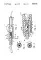
- FIG. 1is an exploded view of the three basic component parts of the electrical connector.
- FIG. 1Ais a plan view of a stamped barrel contact prior to forming.
- FIG. 2is a cross sectional view of the connector joined together with its power cable and ready to receive a contact pin.
- FIG. 3is a sectional view of the electrical connector through lines 3--3 of FIG. 2.
- FIG. 4is a sectional view of the electrical connector through lines 4--4 of FIG. 2.
- FIG. 5is an enlarged cross sectional view of the cooperating elements of the connector.
- the connector 10 shown in FIG. 1has three major components; namely, the inner plastic shield 12, the outer plastic shield 14 and the barrel connector 16.
- the barrel connector 16is rolled from a stamped out beryllium copper alloy as shown in FIG. lA.
- the barrel portion of the connectorhas adjacent multiple longitudinal slats 19 integral with a ring 17 at the back end and a ring 21 at the front end of the barrel.
- the barrel portion of the connectoris integral with a pair of upright strain relief arms 18 and 20 respectively and a pair of crimping arms 22 and 24 respectively.
- a bridge 23joins the barrel portion of the connector with crimping arms 22 and 24 and bridge 25 joins the crimping arms 22 and 24 to the strain relief 18 and 20.
- the inner shield 12is a plastic component having an annular opening 37 through which is fed a polypropylene coated cable 46 as seen in FIG. 2.
- the inner shield 12has an outer ring 26 on its outer surface 29.
- the cable 46containing multiple wire strands 44, is fed through an annular opening 37 and is crimped by arms 18 and 20 on the exterior surface of the cable 46.
- the outer casing of cable 46is stripped at its end to expose wire strands 44.
- the exposed wire strandsare thereafter crimped by arms 22 and 24 to give the wire crimped appearance 42 shown in FIG. 4. After the strain relief 18 and 20 and the crimp arms 22 and 24 are in place the wire cable 46 is pulled backwardly so that the barrel connector 16 is pulled into the inner-shield.
- Stops 30 and 32 located in the inner surface of opening 37prevent the barrel connector 16 from being pulled too far backwards into the annular opening 37.
- the front end 21 of the barrel connectoris approximately flush with the front end 34 of the inner-shield 12.
- the inner-shield 12is then pushed into the outer shield 14 so that the ring 26 engages with the groove 28 in an inner surface of outer shield 14.
- the connectoris ready for engagement with a male connector 38 which is attached to another connector 40.
- the male connector 38is pushed in through opening 39 at the front end o the outer shield 14 and is pushed so that the connector 40 engages at its shoulders 48 with stops 36 on the inner surface of outer shield 14. At this point, the male connector 38 is engaged inside the barrel connector 16 and electrical contact is achieved.
- the inner and outer plastic housingis made from a flame retardant polypropylene or other thermo-plastic.
- the barrel connector 16is made from a beryllium copper spring alloy or phosphor bronze or other spring contact material. Two dissimilar metals can be used in the connector such as phosphor bronze for the barrel and brass or copper alloys for the crimping portion. The materials are joined by electron beam welding.
- the wire cableis made from polypropylene and contains multiple strands of copper wire.
- the electrical connector of this inventioncan carry voltages in excess of 20,000, but will receive a male pin with a minimum of insertion force. Other equivalent materials can be substituted for the materials set forth above in order to make the connector of this invention.
Landscapes
- Details Of Connecting Devices For Male And Female Coupling (AREA)
Abstract
Description
1. Field of the Invention
This invention relates to electrical connectors. More particularly, it refers to high voltage receiving electrical connectors having a barrel contact and low insertion force.
2. Description of the Prior Art
Barrel contact elements having a necked down middle portion are known from U.S. Pat. Nos. 2,422,265; 3,538,491; 4,662,706 and 4,749,357. These contacts have been used in various manners from single female pin receptacles to buss contacts. Most of these prior uses have been as low voltage contacts. High voltage connectors generally have high insertion forces for contact reliability. Unfortunately, these high insertion forces diminish the number of male contacts that can be inserted with a single operation. A connector useful at high voltages with low insertion force and high contact reliability is needed.
I have invented an electrical connector employing a barrel contact integral with a wire crimping and strain relief element which permits low insertion force and significantly reduced voltage drop between female and male connectors.
My connector is a three component device having an outer plastic and inner plastic shield enclosing a beryllium copper spring alloy barrel contact integral with a wire crimping and strain relief element. A high voltage carrying multiple strand wire covered by a cross-linked polypropylene outer casing is threaded through the inner shield. The end of the wire casing is stripped away to expose the wire strands which are crimped by the crimping arms integral with the barrel contact. Another pair of upright arms acting as strain relief elements are crimped to the outer casing. The barrel connector is then retracted into the annular central opening in the inner plastic shield until a front end of the barrel connector is flush with the front end of the inner shield. Two pair of stops on an inner surface of the inner plastic shield prevent retraction of the barrel connector beyond its desired position. A ridge or ring on the outer surface of the inner shield snaps into a groove on an inner surface of the back portion of the outer shield to join the two shields together. The front portion of the outer shield receives a mating male connector which connects to the barrel connector to form a tight fit and a good electrical connection.
The invention may be best understood by those having ordinary skill in the art by reference to the following detailed description when considered in conjunction with the accompanying drawings in which:
FIG. 1 is an exploded view of the three basic component parts of the electrical connector.
FIG. 1A is a plan view of a stamped barrel contact prior to forming.
FIG. 2 is a cross sectional view of the connector joined together with its power cable and ready to receive a contact pin.
FIG. 3 is a sectional view of the electrical connector through lines 3--3 of FIG. 2.
FIG. 4 is a sectional view of the electrical connector throughlines 4--4 of FIG. 2.
FIG. 5 is an enlarged cross sectional view of the cooperating elements of the connector.
Theconnector 10 shown in FIG. 1 has three major components; namely, the innerplastic shield 12, the outerplastic shield 14 and thebarrel connector 16. Thebarrel connector 16 is rolled from a stamped out beryllium copper alloy as shown in FIG. lA. The barrel portion of the connector has adjacent multiplelongitudinal slats 19 integral with aring 17 at the back end and aring 21 at the front end of the barrel. The barrel portion of the connector is integral with a pair of uprightstrain relief arms arms arms bridge 25 joins the crimpingarms strain relief
Theinner shield 12 is a plastic component having anannular opening 37 through which is fed a polypropylene coatedcable 46 as seen in FIG. 2. Theinner shield 12 has anouter ring 26 on itsouter surface 29. Thecable 46, containingmultiple wire strands 44, is fed through anannular opening 37 and is crimped byarms cable 46. The outer casing ofcable 46 is stripped at its end to exposewire strands 44. The exposed wire strands are thereafter crimped byarms appearance 42 shown in FIG. 4. After thestrain relief crimp arms wire cable 46 is pulled backwardly so that thebarrel connector 16 is pulled into the inner-shield.Stops barrel connector 16 from being pulled too far backwards into theannular opening 37. Thefront end 21 of the barrel connector is approximately flush with thefront end 34 of the inner-shield 12. The inner-shield 12 is then pushed into theouter shield 14 so that thering 26 engages with thegroove 28 in an inner surface ofouter shield 14. Thereafter, the connector is ready for engagement with amale connector 38 which is attached to anotherconnector 40. Themale connector 38 is pushed in throughopening 39 at the front end o theouter shield 14 and is pushed so that theconnector 40 engages at its shoulders 48 withstops 36 on the inner surface ofouter shield 14. At this point, themale connector 38 is engaged inside thebarrel connector 16 and electrical contact is achieved.
The inner and outer plastic housing is made from a flame retardant polypropylene or other thermo-plastic. Thebarrel connector 16 is made from a beryllium copper spring alloy or phosphor bronze or other spring contact material. Two dissimilar metals can be used in the connector such as phosphor bronze for the barrel and brass or copper alloys for the crimping portion. The materials are joined by electron beam welding. The wire cable is made from polypropylene and contains multiple strands of copper wire. The electrical connector of this invention, can carry voltages in excess of 20,000, but will receive a male pin with a minimum of insertion force. Other equivalent materials can be substituted for the materials set forth above in order to make the connector of this invention.
Claims (14)
1. A high voltage carrying female electrical connector for receiving male pins comprising
an inner thermo-plastic shield having an inner channel and an outer cylindrical thermo-plastic shield enclosing a portion of the inner shield,
the inner plastic shield having a means on its outer surface for snapping into a groove on an interior surface of the outer shield,
the inner plastic shield enclosing a metal female barrel connector, the connector having a necked down slated barrel portion connected by a first proximal bridge to a pair of wire crimping arms and by a second distal bridge to a pair of strain relief arms, the barrel portion of the connector capable of contacting a male pin,
the outer shield enclosing the inner shield within a first interior channel and capable of enclosing a male connector within a second interior channel with a male pin of the male connector extending into the barrel portion, the first and second channels being open to each other, and
a high voltage carrying cable engaged by the strain relief arms and interior wires of the cable exposed at an end of the cable crimped by the wire crimping arms.
2. The electrical connector of claim 1 wherein the means on the outer surface of the inner shield for snapping into the groove of the interior surface of the outer shield is a ring at right angles to the inner channel of the inner shield.
3. The electrical connector of claim 1 wherein the inner channel of the inner shield has a pair of stops to prevent the barrel connector from being pulled out from a rear end of the shield.
4. The electrical connector of claim 1 wherein the second interior channel of the outer shield has a stop proximal to the first channel to prevent further insertion of a male connector housing.
5. The electrical connector of claim 1 wherein the barrel connector is made from a beryllium copper spring alloy.
6. The electrical connector of claim 1 wherein the barrel connector is made from a phosphor bronze spring alloy.
7. The electrical connector of claim 1 wherein the barrel portion and the strain relief arms and crimping arms are made from dissimilar metals and are joined together by an electron beam weld.
8. The electrical connector of claim 1 wherein the outer and inner shields are made from a flame retardant polypropylene polymer.
9. Method of making the electrical connector of claim 1 wherein the parts are assembled by inserting the cable through the inner channel of the inner shield from a rear end to a front end, exposing the wire strands at an end of the cable and crimping the crimping arms to the wire strands while crimping the strain relief arms to the cable, thereafter pulling the cable backward so that the barrel connector is enclosed within the inner shield and thereafter inserting the inner shield within the first interior channel of the outer shield until it snaps in place.
10. A high voltage carrying female electrical connector for receiving male pins comprising
an inner thermo-plastic shield having an inner annular channel and an annular ring on an outer surface at right angles to the inner channel,
an outer thermo-plastic shield having a first inner channel with an inner annular groove therein for receiving the ring from the inner shield and a second inner channel open to the first channel for receiving another electrical connector housing,
a metal barrel connector integral with a pair of strain relief arms and a pair of crimping arms, the connector being located in a front portion of the inner channel of the inner plastic shield,
a wire cable enclosing multiple strand wire, the cable being stripped at an end to expose the multiple strand wire, the multiple strand wire being crimped together by the crimping arms and the wire cable being secured by the strain relief arms, the wire casing being located within the annular channel of the inner shield behind the barrel connector located within a front portion of the inner shield,
the inner shield outer annular ring being engaged with the outer shield's inner annular groove through the first channel in the outer shield so that the outer shield, inner shield, wire cable and barrel connector are permanently joined together and a male connector can be connected to the barrel connector through the second channel in the outer shield.
11. An electrical connector according to claim 10 wherein a pair of stops within the inner shield prevents the barrel connector from being pushed backward from the front portion of the inner channel.
12. An electrical connector according to claim 10 wherein the barrel connector is made from a beryllium copper spring alloy.
13. An electrical connector according to claim 10 wherein the barrel connector is made from a phosphor bronze spring alloy.
14. An electrical connector according to claim 10 wherein the second interior channel of the outer shield has a stop proximal to the first channel to prevent further insertion of a male connector housing.
Priority Applications (1)
| Application Number | Priority Date | Filing Date | Title |
|---|---|---|---|
| US07/531,522US5033982A (en) | 1990-05-31 | 1990-05-31 | Electrical connector |
Applications Claiming Priority (1)
| Application Number | Priority Date | Filing Date | Title |
|---|---|---|---|
| US07/531,522US5033982A (en) | 1990-05-31 | 1990-05-31 | Electrical connector |
Publications (1)
| Publication Number | Publication Date |
|---|---|
| US5033982Atrue US5033982A (en) | 1991-07-23 |
Family
ID=24117978
Family Applications (1)
| Application Number | Title | Priority Date | Filing Date |
|---|---|---|---|
| US07/531,522Expired - Fee RelatedUS5033982A (en) | 1990-05-31 | 1990-05-31 | Electrical connector |
Country Status (1)
| Country | Link |
|---|---|
| US (1) | US5033982A (en) |
Cited By (35)
| Publication number | Priority date | Publication date | Assignee | Title |
|---|---|---|---|---|
| US5474479A (en)* | 1994-09-28 | 1995-12-12 | The Whitaker Corporation | Louvered contact electrical connector |
| WO1998043321A1 (en)* | 1997-03-20 | 1998-10-01 | Ingos Elektronik-Handelsgesellschaft Mbh | Socket with contact regions disposed in the form of a hyperboloid |
| US6254439B1 (en)* | 1998-09-10 | 2001-07-03 | Yazaki Corporation | Female type terminal, assembling method of female type terminal, and connector for female type terminal |
| DE10005297A1 (en)* | 2000-02-07 | 2001-08-16 | Siemens Ag | Contact piece for an electrical connector and method for its production |
| US6358104B2 (en)* | 2000-01-10 | 2002-03-19 | Delphi Technologies, Inc. | High current terminal |
| US6482049B1 (en) | 1999-07-16 | 2002-11-19 | Amphenol Corporation | Radially resilient electrical connector |
| DE10163228A1 (en)* | 2001-12-21 | 2003-07-17 | Volkswagen Ag | Electrical contact used in vehicles comprises a base body with crimped vanes made from a cold-deformed material, and contact tongues made from an electrical contact material of high strength and elasticity |
| US6729895B1 (en) | 2002-06-17 | 2004-05-04 | Clyde W. Bryan | Electrical connector |
| US6767260B2 (en) | 2002-02-28 | 2004-07-27 | Qa Technology Company, Inc. | Hyperboloid electrical contact |
| US6837756B2 (en) | 2001-10-05 | 2005-01-04 | Amphenol Corporation | Radially resilient electrical connector and method of making the same |
| US6899571B1 (en) | 2000-05-11 | 2005-05-31 | Konnektech Ltd. | Radially resilient electrical connector with welded grid |
| US7048596B2 (en) | 2001-10-18 | 2006-05-23 | Konnektech, Ltd. | Electrical connector grid anchor and method of making the same |
| US7387549B1 (en) | 2007-02-01 | 2008-06-17 | K.S. Terminals, Inc. | Electrical socket connector and female terminal therein |
| WO2008079588A1 (en)* | 2006-12-20 | 2008-07-03 | 3M Innovative Properties Company | Connection article for a cable, holder for a connector of such a connection article, and kit for connecting cables |
| US20080293287A1 (en)* | 2007-04-03 | 2008-11-27 | Lear Corporation | Electrical terminal assembly and method of using the electrical terminal assembly |
| US20120164862A1 (en)* | 2010-12-23 | 2012-06-28 | Hon Hai Precision Industry Co., Ltd. | Electrical connector having improved contact member |
| US20130035003A1 (en)* | 2010-04-14 | 2013-02-07 | Erich Frank | Electrical plug-in connector element and plug-in connector part comprising a plurality of plug-in connector elements |
| US8628335B1 (en)* | 2012-12-07 | 2014-01-14 | Tyco Electronics Corporation | Power terminal connector |
| US9236682B2 (en) | 2013-02-15 | 2016-01-12 | Lear Corporation | Cylindrical electric connector with biased contact |
| US9337466B2 (en) | 2012-12-07 | 2016-05-10 | Tyco Electronics Corporation | Power terminal connector |
| CN105588084A (en)* | 2014-11-18 | 2016-05-18 | 厦门广泓工贸有限公司 | Electrically connected female terminal and LED lamp applied by same |
| CN106025643A (en)* | 2016-06-30 | 2016-10-12 | 瑞安市超声电器厂 | High-voltage connector |
| EP3252874A1 (en) | 2016-05-03 | 2017-12-06 | Eaxtron | Female contact sleeve, connector using the sleeve and manufacturing method |
| CN107978906A (en)* | 2016-10-21 | 2018-05-01 | 住友电装株式会社 | Shield terminal and outer conductor terminal |
| US9985376B2 (en)* | 2016-02-29 | 2018-05-29 | Tyco Electronics (Shanghai) Co. Ltd. | Connection member and connection assembly |
| US20180358757A1 (en)* | 2017-06-08 | 2018-12-13 | Delphi Technologies, Llc | Method for forming a shielded electrical terminal and an electrical terminal formed by said method |
| US20190006783A1 (en)* | 2017-06-28 | 2019-01-03 | Tatsuta Electric Wire & Cable Co., Ltd. | Connector, Electric Wire with Connector, and Medical Device Sensor |
| US10347998B2 (en) | 2017-06-28 | 2019-07-09 | Tatsuta Electric Wire & Cable Co., Ltd. | Crimp terminal, electric wire with crimp terminal, and medical device sensor |
| USD897478S1 (en)* | 2018-07-10 | 2020-09-29 | James J. Rofkahr, Jr. | Cylindrical trigger dampening absorber |
| USD926914S1 (en) | 2018-07-10 | 2021-08-03 | James J. Rofkahr, Jr. | Cylindrical trigger dampening absorber |
| USD934374S1 (en) | 2018-07-10 | 2021-10-26 | James J. Rofkahr, Jr. | Cylindrical trigger dampening absorber |
| GB2599618A (en)* | 2020-07-27 | 2022-04-13 | Aquasium Tech Limited | Electron beam welding apparatus |
| USD953327S1 (en)* | 2020-09-14 | 2022-05-31 | Yokogawa Electric Corporation | Wireless communication module |
| CN115867011A (en)* | 2022-11-18 | 2023-03-28 | 海拉(厦门)电气有限公司 | A shielding cover installation structure and installation method of an automobile motor speed sensor |
| EP4312313A1 (en) | 2022-07-28 | 2024-01-31 | Aptiv Technologies Limited | Electrical connector having a ferrule and a crimp portion and method for manufacturing a cable therewith |
Citations (7)
| Publication number | Priority date | Publication date | Assignee | Title |
|---|---|---|---|---|
| US2071572A (en)* | 1935-12-30 | 1937-02-23 | Gen Motors Corp | Radio shield for spark plugs |
| US2258810A (en)* | 1940-01-05 | 1941-10-14 | Gen Motors Corp | Shielded aircraft spark plug |
| US2762021A (en)* | 1955-02-18 | 1956-09-04 | Auburn Spark Plug Co Inc | Spark plug terminal connector |
| US3641478A (en)* | 1969-07-03 | 1972-02-08 | Nottingham & Co Inc J B | Separable plug |
| US3914003A (en)* | 1972-12-14 | 1975-10-21 | Kabel Metallwerke Ghh | Spark plug socket for internal combustion engines |
| US4550972A (en)* | 1984-04-09 | 1985-11-05 | Amp Incorporated | Cylindrical socket contact |
| US4906202A (en)* | 1989-03-13 | 1990-03-06 | General Motors Corporation | Deep well ignition cable terminal assembly |
- 1990
- 1990-05-31USUS07/531,522patent/US5033982A/ennot_activeExpired - Fee Related
Patent Citations (7)
| Publication number | Priority date | Publication date | Assignee | Title |
|---|---|---|---|---|
| US2071572A (en)* | 1935-12-30 | 1937-02-23 | Gen Motors Corp | Radio shield for spark plugs |
| US2258810A (en)* | 1940-01-05 | 1941-10-14 | Gen Motors Corp | Shielded aircraft spark plug |
| US2762021A (en)* | 1955-02-18 | 1956-09-04 | Auburn Spark Plug Co Inc | Spark plug terminal connector |
| US3641478A (en)* | 1969-07-03 | 1972-02-08 | Nottingham & Co Inc J B | Separable plug |
| US3914003A (en)* | 1972-12-14 | 1975-10-21 | Kabel Metallwerke Ghh | Spark plug socket for internal combustion engines |
| US4550972A (en)* | 1984-04-09 | 1985-11-05 | Amp Incorporated | Cylindrical socket contact |
| US4906202A (en)* | 1989-03-13 | 1990-03-06 | General Motors Corporation | Deep well ignition cable terminal assembly |
Cited By (52)
| Publication number | Priority date | Publication date | Assignee | Title |
|---|---|---|---|---|
| US5474479A (en)* | 1994-09-28 | 1995-12-12 | The Whitaker Corporation | Louvered contact electrical connector |
| WO1998043321A1 (en)* | 1997-03-20 | 1998-10-01 | Ingos Elektronik-Handelsgesellschaft Mbh | Socket with contact regions disposed in the form of a hyperboloid |
| US6254439B1 (en)* | 1998-09-10 | 2001-07-03 | Yazaki Corporation | Female type terminal, assembling method of female type terminal, and connector for female type terminal |
| US6482049B1 (en) | 1999-07-16 | 2002-11-19 | Amphenol Corporation | Radially resilient electrical connector |
| US6358104B2 (en)* | 2000-01-10 | 2002-03-19 | Delphi Technologies, Inc. | High current terminal |
| DE10005297A1 (en)* | 2000-02-07 | 2001-08-16 | Siemens Ag | Contact piece for an electrical connector and method for its production |
| DE10005297C2 (en)* | 2000-02-07 | 2001-12-20 | Siemens Ag | Contact piece for an electrical connector and method for its production |
| US6899571B1 (en) | 2000-05-11 | 2005-05-31 | Konnektech Ltd. | Radially resilient electrical connector with welded grid |
| US6837756B2 (en) | 2001-10-05 | 2005-01-04 | Amphenol Corporation | Radially resilient electrical connector and method of making the same |
| US7048596B2 (en) | 2001-10-18 | 2006-05-23 | Konnektech, Ltd. | Electrical connector grid anchor and method of making the same |
| DE10163228A1 (en)* | 2001-12-21 | 2003-07-17 | Volkswagen Ag | Electrical contact used in vehicles comprises a base body with crimped vanes made from a cold-deformed material, and contact tongues made from an electrical contact material of high strength and elasticity |
| US7191518B2 (en) | 2002-02-28 | 2007-03-20 | Qa Technology Company, Inc. | Method of making a hyperboloid electrical contact |
| US20040237301A1 (en)* | 2002-02-28 | 2004-12-02 | Qa Technology Company, Inc. | Hyperboloid electrical contact |
| US6767260B2 (en) | 2002-02-28 | 2004-07-27 | Qa Technology Company, Inc. | Hyperboloid electrical contact |
| US6729895B1 (en) | 2002-06-17 | 2004-05-04 | Clyde W. Bryan | Electrical connector |
| RU2399127C1 (en)* | 2006-12-20 | 2010-09-10 | 3М Инновейтив Пропертиз Компани | Connection device for cables, holder for socket of such connection device and set for connection of cables |
| WO2008079588A1 (en)* | 2006-12-20 | 2008-07-03 | 3M Innovative Properties Company | Connection article for a cable, holder for a connector of such a connection article, and kit for connecting cables |
| US20100022119A1 (en)* | 2006-12-20 | 2010-01-28 | Christophe Desard | Connector article for a cable, holder for a connector of such a connection article, and kit for connecting cables |
| US7789718B2 (en) | 2006-12-20 | 2010-09-07 | 3M Innovative Properties Company | Connector article for a cable, holder for a connector of such a connection article, and kit for connecting cables |
| KR101327578B1 (en) | 2006-12-20 | 2013-11-12 | 쓰리엠 이노베이티브 프로퍼티즈 컴파니 | Connection article for a cable, holder for a connector of such a connection article, and kit for connecting cables |
| US20080188142A1 (en)* | 2007-02-01 | 2008-08-07 | K.S. Terminals, Inc. | Socket connector and female terminal therein |
| US20080188143A1 (en)* | 2007-02-01 | 2008-08-07 | K.S. Terminals, Inc. | Socket connector and female terminal therein |
| US7438608B2 (en) | 2007-02-01 | 2008-10-21 | K.S. Terminals, Inc. | Socket connector and female terminal therein |
| US7387549B1 (en) | 2007-02-01 | 2008-06-17 | K.S. Terminals, Inc. | Electrical socket connector and female terminal therein |
| US20080293287A1 (en)* | 2007-04-03 | 2008-11-27 | Lear Corporation | Electrical terminal assembly and method of using the electrical terminal assembly |
| US7789720B2 (en)* | 2007-04-03 | 2010-09-07 | Lear Corporation | Electrical terminal assembly and method of using the electrical terminal assembly |
| US20130035003A1 (en)* | 2010-04-14 | 2013-02-07 | Erich Frank | Electrical plug-in connector element and plug-in connector part comprising a plurality of plug-in connector elements |
| US9004955B2 (en)* | 2010-04-14 | 2015-04-14 | Pfisterer Kontaktsyteme GmbH | Electrical plug-in connector element and plug-in connector part comprising a plurality of plug-in connector elements |
| US20120164862A1 (en)* | 2010-12-23 | 2012-06-28 | Hon Hai Precision Industry Co., Ltd. | Electrical connector having improved contact member |
| US8454395B2 (en)* | 2010-12-23 | 2013-06-04 | Hon Hai Precision Industry Co., Ltd. | Electrical connector having improved contact member |
| US9337466B2 (en) | 2012-12-07 | 2016-05-10 | Tyco Electronics Corporation | Power terminal connector |
| US8628335B1 (en)* | 2012-12-07 | 2014-01-14 | Tyco Electronics Corporation | Power terminal connector |
| US9236682B2 (en) | 2013-02-15 | 2016-01-12 | Lear Corporation | Cylindrical electric connector with biased contact |
| CN105588084A (en)* | 2014-11-18 | 2016-05-18 | 厦门广泓工贸有限公司 | Electrically connected female terminal and LED lamp applied by same |
| CN105588084B (en)* | 2014-11-18 | 2020-08-28 | 厦门广泓工贸有限公司 | Electric connection female terminal and LED lamp using same |
| US9985376B2 (en)* | 2016-02-29 | 2018-05-29 | Tyco Electronics (Shanghai) Co. Ltd. | Connection member and connection assembly |
| US10050366B2 (en) | 2016-05-03 | 2018-08-14 | Eaxtron (Sarl) | Sleeve for socket contact, connector using the sleeve, and manufacturing method |
| EP3252874A1 (en) | 2016-05-03 | 2017-12-06 | Eaxtron | Female contact sleeve, connector using the sleeve and manufacturing method |
| CN106025643A (en)* | 2016-06-30 | 2016-10-12 | 瑞安市超声电器厂 | High-voltage connector |
| CN107978906A (en)* | 2016-10-21 | 2018-05-01 | 住友电装株式会社 | Shield terminal and outer conductor terminal |
| US20180358757A1 (en)* | 2017-06-08 | 2018-12-13 | Delphi Technologies, Llc | Method for forming a shielded electrical terminal and an electrical terminal formed by said method |
| US10516238B2 (en)* | 2017-06-08 | 2019-12-24 | Delphi Technologies, Llc | Method for forming a shielded electrical terminal and an electrical terminal formed by said method |
| US20190006783A1 (en)* | 2017-06-28 | 2019-01-03 | Tatsuta Electric Wire & Cable Co., Ltd. | Connector, Electric Wire with Connector, and Medical Device Sensor |
| US10347998B2 (en) | 2017-06-28 | 2019-07-09 | Tatsuta Electric Wire & Cable Co., Ltd. | Crimp terminal, electric wire with crimp terminal, and medical device sensor |
| US10374350B2 (en)* | 2017-06-28 | 2019-08-06 | Tatsuta Electric Wire & Cable Co., Ltd. | Connector, electric wire with connector, and medical device sensor |
| USD897478S1 (en)* | 2018-07-10 | 2020-09-29 | James J. Rofkahr, Jr. | Cylindrical trigger dampening absorber |
| USD926914S1 (en) | 2018-07-10 | 2021-08-03 | James J. Rofkahr, Jr. | Cylindrical trigger dampening absorber |
| USD934374S1 (en) | 2018-07-10 | 2021-10-26 | James J. Rofkahr, Jr. | Cylindrical trigger dampening absorber |
| GB2599618A (en)* | 2020-07-27 | 2022-04-13 | Aquasium Tech Limited | Electron beam welding apparatus |
| USD953327S1 (en)* | 2020-09-14 | 2022-05-31 | Yokogawa Electric Corporation | Wireless communication module |
| EP4312313A1 (en) | 2022-07-28 | 2024-01-31 | Aptiv Technologies Limited | Electrical connector having a ferrule and a crimp portion and method for manufacturing a cable therewith |
| CN115867011A (en)* | 2022-11-18 | 2023-03-28 | 海拉(厦门)电气有限公司 | A shielding cover installation structure and installation method of an automobile motor speed sensor |
Similar Documents
| Publication | Publication Date | Title |
|---|---|---|
| US5033982A (en) | Electrical connector | |
| US4690481A (en) | Coaxial coupling | |
| US7018220B2 (en) | Multiple pole connector | |
| EP0122700A2 (en) | Coaxial electrical connector for multiple outer conductor coaxial cable | |
| US5542861A (en) | Coaxial connector | |
| US6089903A (en) | Electrical connector with automatic conductor termination | |
| US4310213A (en) | Electrical connector kit | |
| US5147230A (en) | Two piece electrical female terminal | |
| US4412717A (en) | Coaxial connector plug | |
| US4453796A (en) | Coaxial connector plug | |
| US5037328A (en) | Foldable dielectric insert for a coaxial contact | |
| US4717354A (en) | Solder cup connector | |
| US3721943A (en) | Electrical connecting device | |
| US4963102A (en) | Electrical connector of the hermaphroditic type | |
| US4655534A (en) | Right angle coaxial connector | |
| US5749756A (en) | Sealed corrosion-proof crimped terminal of splice | |
| US3670293A (en) | Shielded wire connectors | |
| EP0501629A1 (en) | Cable strain relief back shell | |
| US4768970A (en) | Electrical connector plug assembly for sealed electrical connection | |
| EP2475047B1 (en) | Electrical contact with embedded wiring | |
| GB1077332A (en) | An electrical contact socket | |
| US4278317A (en) | Formed socket contact with reenforcing ridge | |
| US20040110427A1 (en) | Cable end connector and method of assembling the same | |
| US4374607A (en) | Electrical pin and socket connector | |
| US4405195A (en) | Pin and socket connector |
Legal Events
| Date | Code | Title | Description |
|---|---|---|---|
| AS | Assignment | Owner name:SUN MICROSTAMPING, INC., 1A CORP. OF RI, FLORIDA Free format text:ASSIGNMENT OF ASSIGNORS INTEREST.;ASSIGNOR:LUCAS, DEREK A.;REEL/FRAME:005322/0862 Effective date:19900531 | |
| FPAY | Fee payment | Year of fee payment:4 | |
| REMI | Maintenance fee reminder mailed | ||
| LAPS | Lapse for failure to pay maintenance fees | ||
| FP | Lapsed due to failure to pay maintenance fee | Effective date:19990723 | |
| STCH | Information on status: patent discontinuation | Free format text:PATENT EXPIRED DUE TO NONPAYMENT OF MAINTENANCE FEES UNDER 37 CFR 1.362 |