US5033457A - Air assisted medical devices - Google Patents
Air assisted medical devicesDownload PDFInfo
- Publication number
- US5033457A US5033457AUS07/370,895US37089589AUS5033457AUS 5033457 AUS5033457 AUS 5033457AUS 37089589 AUS37089589 AUS 37089589AUS 5033457 AUS5033457 AUS 5033457A
- Authority
- US
- United States
- Prior art keywords
- air
- bag
- air bag
- limb
- body part
- Prior art date
- Legal status (The legal status is an assumption and is not a legal conclusion. Google has not performed a legal analysis and makes no representation as to the accuracy of the status listed.)
- Expired - Lifetime
Links
- 238000010276constructionMethods0.000abstractdescription6
- 239000003570airSubstances0.000description104
- 210000003414extremityAnatomy0.000description20
- 210000000629knee jointAnatomy0.000description12
- 239000000463materialSubstances0.000description9
- 210000002683footAnatomy0.000description6
- 210000001503jointAnatomy0.000description5
- 210000002414legAnatomy0.000description5
- 210000000323shoulder jointAnatomy0.000description5
- 238000002560therapeutic procedureMethods0.000description4
- 239000004033plasticSubstances0.000description3
- 229920003023plasticPolymers0.000description3
- 210000003423ankleAnatomy0.000description2
- 230000017531blood circulationEffects0.000description2
- 230000001276controlling effectEffects0.000description2
- 230000001351cycling effectEffects0.000description2
- 239000004744fabricSubstances0.000description2
- 230000005484gravityEffects0.000description2
- 210000001624hipAnatomy0.000description2
- 230000004048modificationEffects0.000description2
- 238000012986modificationMethods0.000description2
- 230000000541pulsatile effectEffects0.000description2
- 230000006641stabilisationEffects0.000description2
- 238000011105stabilizationMethods0.000description2
- 229920002799BoPETPolymers0.000description1
- OKTJSMMVPCPJKN-UHFFFAOYSA-NCarbonChemical compound[C]OKTJSMMVPCPJKN-UHFFFAOYSA-N0.000description1
- 229920000271Kevlar®Polymers0.000description1
- 239000005041Mylar™Substances0.000description1
- 239000004677NylonSubstances0.000description1
- 239000004698PolyethyleneSubstances0.000description1
- 239000012080ambient airSubstances0.000description1
- 239000003638chemical reducing agentSubstances0.000description1
- 230000008602contractionEffects0.000description1
- 230000000694effectsEffects0.000description1
- 230000005611electricityEffects0.000description1
- 229910002804graphiteInorganic materials0.000description1
- 239000010439graphiteSubstances0.000description1
- 230000003100immobilizing effectEffects0.000description1
- 239000004761kevlarSubstances0.000description1
- 210000003127kneeAnatomy0.000description1
- 239000002184metalSubstances0.000description1
- 210000003205muscleAnatomy0.000description1
- 229920001778nylonPolymers0.000description1
- 210000004197pelvisAnatomy0.000description1
- -1polyethylenePolymers0.000description1
- 229920000573polyethylenePolymers0.000description1
- 230000001105regulatory effectEffects0.000description1
- 230000000284resting effectEffects0.000description1
- 238000007789sealingMethods0.000description1
- 238000005728strengtheningMethods0.000description1
- 210000002303tibiaAnatomy0.000description1
- 210000000689upper legAnatomy0.000description1
- 238000009941weavingMethods0.000description1
- 210000000707wristAnatomy0.000description1
Images
Classifications
- A—HUMAN NECESSITIES
- A61—MEDICAL OR VETERINARY SCIENCE; HYGIENE
- A61F—FILTERS IMPLANTABLE INTO BLOOD VESSELS; PROSTHESES; DEVICES PROVIDING PATENCY TO, OR PREVENTING COLLAPSING OF, TUBULAR STRUCTURES OF THE BODY, e.g. STENTS; ORTHOPAEDIC, NURSING OR CONTRACEPTIVE DEVICES; FOMENTATION; TREATMENT OR PROTECTION OF EYES OR EARS; BANDAGES, DRESSINGS OR ABSORBENT PADS; FIRST-AID KITS
- A61F5/00—Orthopaedic methods or devices for non-surgical treatment of bones or joints; Nursing devices ; Anti-rape devices
- A61F5/01—Orthopaedic devices, e.g. long-term immobilising or pressure directing devices for treating broken or deformed bones such as splints, casts or braces
- A—HUMAN NECESSITIES
- A61—MEDICAL OR VETERINARY SCIENCE; HYGIENE
- A61H—PHYSICAL THERAPY APPARATUS, e.g. DEVICES FOR LOCATING OR STIMULATING REFLEX POINTS IN THE BODY; ARTIFICIAL RESPIRATION; MASSAGE; BATHING DEVICES FOR SPECIAL THERAPEUTIC OR HYGIENIC PURPOSES OR SPECIFIC PARTS OF THE BODY
- A61H1/00—Apparatus for passive exercising; Vibrating apparatus; Chiropractic devices, e.g. body impacting devices, external devices for briefly extending or aligning unbroken bones
- A61H1/02—Stretching or bending or torsioning apparatus for exercising
- A—HUMAN NECESSITIES
- A61—MEDICAL OR VETERINARY SCIENCE; HYGIENE
- A61H—PHYSICAL THERAPY APPARATUS, e.g. DEVICES FOR LOCATING OR STIMULATING REFLEX POINTS IN THE BODY; ARTIFICIAL RESPIRATION; MASSAGE; BATHING DEVICES FOR SPECIAL THERAPEUTIC OR HYGIENIC PURPOSES OR SPECIFIC PARTS OF THE BODY
- A61H2201/00—Characteristics of apparatus not provided for in the preceding codes
- A61H2201/01—Constructive details
- A61H2201/0173—Means for preventing injuries
- A61H2201/018—By limiting the applied torque or force
- A—HUMAN NECESSITIES
- A61—MEDICAL OR VETERINARY SCIENCE; HYGIENE
- A61H—PHYSICAL THERAPY APPARATUS, e.g. DEVICES FOR LOCATING OR STIMULATING REFLEX POINTS IN THE BODY; ARTIFICIAL RESPIRATION; MASSAGE; BATHING DEVICES FOR SPECIAL THERAPEUTIC OR HYGIENIC PURPOSES OR SPECIFIC PARTS OF THE BODY
- A61H2201/00—Characteristics of apparatus not provided for in the preceding codes
- A61H2201/12—Driving means
- A61H2201/1238—Driving means with hydraulic or pneumatic drive
- A61H2201/1246—Driving means with hydraulic or pneumatic drive by piston-cylinder systems
Definitions
- the present inventionrelates to medical devices for use in the positioning and movement of limbs or joints. More particularly, the present invention relates to air assisted devices which are capable of providing continuous passive motion asssistance or immobilization for stabilization or fracture fixation.
- Typical devices used for providing continuous passive motion for joints and limbs, such as motor and cable arrangements,are bulky and awkward.
- Typical devices for immobilization of joints, such as casts, orthoses, custom splints, and abduction pillows,are heavy, and difficult and uncomfortable to wear. None of the devices in current use are simple, comfortable, and inexpensive.
- the present inventionis an air assisted device for positioning or moving a limb or a joint.
- the deviceis lightweight, comfortable and easy to wear and use, and relatively inexpensive.
- the deviceuses compressed air as a motive force.
- the devicemay be used either to assist motion of a limb or to resist motion of a limb.
- the air assisted deviceis a one piece air bag with bellows or accordion-like construction to allow controlled variable degrees of expansion.
- the bagIn its unexpanded state, the bag is collapsed and occupies very little space.
- the unexpanded bagis placed between a limb to be positioned and a relatively fixed body part or other surface.
- the bagexpands and moves the limb away from the body part or other surface. If the bag is maintained in an expanded condition, it immobilizes the limb relative to the body part or other surface. As the bag deflates, the limb returns to its original position.
- the particular shape of the bagis custom fit for the particular application for which the bag is to be used, i.e., positioning a shoulder joint, a knee joint, etc., or immobilizing a particular limb.
- the air assisted deviceutilizes a pneumatic piston and cylinder unit to provide the motive force for positioning two relatively movable parts.
- the piston and cylinder unitis disposed between two parts which are preferably hingedly connected.
- the pistonis connected to one of the parts and the cylinder is connected to the other part.
- the air deviceis placed between a limb to be positioned and a relatively fixed body part or other surface.
- the pistonmoves outwardly, moving one of the relatively movable parts away from the other part. Relative movement of the parts moves the limb toward or away from the body part or other surface.
- the piston and cylinder unitis maintained in an expanded condition, it immobilizes the limb or joint. As the air is released from the cylinder, the limb returns to its original position.
- the two relatively movable partsare formed to have a particular shape, i.e., custom fit for the particular application for which the device is to be used.
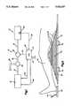
- FIG. 1is a schematic illustration of a system including an air assisted device in accordance with the present invention
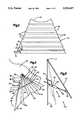
- FIG. 2is a schematic end view of an air bag for use in a system as shown in FIG. 1, the air bag being shown in the deflated condition and designed for providing continuous passive motion to a knee joint;
- FIG. 3is a schematic end view of the air bag of FIG. 2 in an inflated condition
- FIG. 4is a schematic illustration of an air bag usable for a shoulder joint.
- FIG. 5is a schematic illustration of an air assisted device in accordance with the present invention and incorporating a piston and cylinder arrangement.
- FIG. 1illustrates schematically a system 10 which supplies air under pressure for predetermined periods of time to move parts of an air assisted device 12 relative to each other.
- the system 10includes an electronic control unit 14 connected to a source of electricity 16.
- the electronic control unit 14controls through wiring 18 a compressor 20.
- the compressor 20is powered by electric power supplied from the control unit 14 via wiring 22.
- the compressor 20under the control of the control unit 14 compresses ambient air and supplies the compressed air through a supply pipe 24 to a supply valve 26.
- the supply valve 26is optionally connected to a fixed source 28 of pressurized air such as, for example, a pressurized air line in a hospital room.
- the system 10may thus be operated with a provided source 28 of pressurized air, or may supply its own pressurized air via the compressor 20.
- Pressurized air from the supply valve 26passes through piping 30 to a control valve 32. From the control valve 32, a supply line 34 leads to the air assisted device 12.
- the control valve 32may, if desired, be constructed within or on the device 12.
- a pressure sensor 36 in or on the device 12senses the air pressure in the device 12 and provides a control signal via wiring 38 to the electronic control unit 14.
- the electronic control unit 14also includes a timer 40 which is settable to supply air to the device 12 for any predetermined period of time, and thus for cycling the operation of the device 12.
- the electronic control unitprovides control signals via line 42 to the control valve 32 to regulate the air supply to the device 12.
- the electronic control unit 14includes a programmable microprocessor.
- the control unit 14is programmed to supply air to the device 12 for predetermined periods of time, in order to move apart the relatively movable parts of the device 12 a certain distance over a certain period of time.
- the control unit 14also controls the control valve 32 to release air from the device 12 in accordance with a predetermined pattern.
- the time duration and sequenceis set by the patient or by medical personnel in order to provide the needed therapy.
- the control unit 14 including the sensor means 36 and the timer 40, by controlling the compressor 20 and the valve 32 and thus the air pressure and time of supply of the air,may provide any desired range of motion to the device 12.
- the device 12ais a one-piece air bag having accordion-like ridges spaced thereabout to provide for controlled expansion of the air bag.
- FIGS. 2 and 3illustrate schematically an air bag 12a in, respectively, almost completely deflated and inflated conditions, FIG. 3 being an end view of the bag 12a.
- the airbag 12ais shaped to fit under a knee joint 43 and is shaped with a recess 13 to receive the leg. As air is supplied under pressure, the air bag 12a expands from the condition shown in FIG. 2 to the inflated condition shown in FIG. 3 to flex the knee joint 43.
- Sensor means 36senses the air pressure inside the bag 12a and outputs a signal through line 38 back to the control unit 14.
- the air bag 12ahas a relatively flat base 44 for stability. Loops or attachments 45 receive straps for securing the bag 12a to an underlying bed (not shown). Straps may also be provided to prevent lateral movement of the bag 12a, especially when the bag 12a is in an intermediate position (i.e., semi-inflated).
- the strapsmay be inelastic or elastic and may be attached either to the bed or to the leg, or may be part of (formed as) a filament within the bag 12a itself.
- the bag 12ais continuously inflated and deflated to provide continuous passive motion to the knee joint 43 for therapy purposes.
- the bag 12aoperates on relatively low air pressure, for safety and for light weight and portable construction.
- the medical uses for which the device 12a is usedrapid motion is not generally necessary, and accordingly the low operating pressure of the system 10 is suitable.
- the outside pressurized air supply 28(FIG. 1) is of a higher pressure than needed, the pressurized air supplied therefrom may be passed through a pressure reducer valve (not shown) prior to being supplied to the remainder of the system 10.
- the air bag 12aupon the supply of pressurized air thereto, expands in an accordion-like manner (as a bellows).
- the material of which the bag 12a is madedoes not necessarily stretch although it may somewhat, but rather the expansion comes primarily when the various surfaces of the bag 12a are repositioned relative to one another.
- Various fabrics or plasticsmay be utilized to form the bag 12a.
- the material of which the bag 12a is madeis preferably a light weight polymeric material.
- the preferred materialis Mylar, reinforced with Kevlar, nylon, or graphite polyethylene, or metal filaments as now used in surgical gloves. The material must be selected to, first, retain pressurized air therein, and to retain a particular shape when inflated.
- the accordion-like ridges 46may be made of differing degrees of resistance to straightening and flexing, in order to vary the rate and/or sequence of expansion of various portions of the bag 12a.
- the material of which the bag 12a is madehas areas of rigidity interleaved with areas of more elasticity, to provide the desired expansion effect.
- the materialmay also be designed to be self-sealing, like an automobile tire.
- Incoming air under pressureis supplied for a period of time as determined by the control unit 14.
- the bag 12aexpands from its deflated condition shown in FIG. 2 to its inflated condition shown in FIG. 3.
- the control unit 14operates the two-way valve 32 to allow air to pass out of the bag 12a through the pipe 34 and the valve 32.
- the airis forced from the bag 12a by gravity, i.e., the weight of the leg pressing the bag 12a back to its deflated condition.
- the valve 32is controllable to provide a variable resistance to air outflow therethrough, in order to vary the deflation rate of the bag 12a.
- the bag 12amay be maintained in its inflated condition as shown in FIG. 3, or in a semi-inflated condition intermediate that of FIGS. 2 and 3, for any period of time as desired.
- the bag 12aIncreasing the amount of air in the bag 12a results in further flexion of the knee joint 43.
- the bag 12aAs the bag 12a is inflated from its condition shown in FIG. 2 to its fully inflated condition shown in FIG. 3, the bag 12a passes through a range of intermediate positions during which the knee joint 43 is flexed to varying degrees.
- the degree of flexion, and the amount of time required to attain that degree of flexion,are thus controllable by means of the control unit 14 with its timing capabilities.
- the pressure within the air bag 12ais easily regulated to provide exact control of the degree of flexion and extension of the joint 43, a capability not provided by the typical motor and cable arrangement.
- the system 10provides a pulsatile airflow which forces air into the bag 12a for a set period of time, then shuts off, allowing deflation of the bag 12a. This cycling operation provides the continuous passive motion which is desired for exercise and therapy of the joint 43.
- a base unit 48disposed between the base 44 of the bag 12a and a relatively fixed surface, such as a hospital bed (not shown), on which the patient is disposed.
- the base unit 48is either a separate inflatable portion of the bag 12a, or a separate attachable air bag.
- the base unit 48may accordingly be varied in thickness by filling with more or less air, to limit the degree of extension of the knee joint 43, i.e., to provide an initial degree of flexion.
- the base unit 48may be a board or other kind of prop placed underneath the air bag 12a.
- a foot piece 50may be placed underneath the patient's foot and ankle to provide proper positioning thereof during the providing of continuous passive motion to the knee joint 43.
- the foot piece 50may be a separate unit, or it may be a part of the air bag 12a.
- the foot piece 50may be a further inflatable portion of the bag 12a or may be separately inflatable through an air supply line 51.
- the patient's footmay thus be raised relative to the surface on which the person is resting, in order to force full extension of the knee joint 43.
- FIG. 2shows the bag 12a in an almost completely deflated condition, and the knee joint 43 is almost completely extended.
- FIG. 4illustrates schematically an air bag 12b which is designed and fitted for use in immobilization or passive motion assistance of a shoulder joint 68.
- the bag 12bhas a first surface 52 which is fitted for contact with the arm 54 of the patient, and a second surface 56 which is fitted for contact with the relatively fixed torso 58 of the patient.
- the bag 12bis attached to the upper arm 54 by means of straps 60 and 62 using, for example, a VELCRO-type fastening.
- the bag 12bmay also have VELCRO-type fastening to attach to the patient's shirt or other garment, since the bag 12b is so light in weight.
- the bag 12bis attached to the torso 58 by straps 64 and 66 fitting around the torso 58 to secure the bag 12b in position.
- Controlled supply of pressurized air into and out of the bag 12b by means of the air supply pipe 34moves the first surface 52 relative to the second surface 56 and therefore moves the upper arm 54 relative to the torso 58 about the shoulder joint 68.
- a plurality of accordion-like ridges 70interconnect the first and second surfaces 52 and 56.
- the accordion-like ridges 70provide controlled expansion of the air bag 12b and positioning of the first surface 52 relative to the second surface 56. Because the bag 12b, like the bag 12a shown in FIGS. 2 and 3, is made of a light weight plastic or fabric-type material, it may, in all instances, be fitted to closely conform to the surfaces which it contacts.
- the surface 52 of the bag 12bis shaped to conform to the shape of the upper arm 54.
- the surface 56 of the bag 12bis shaped to conform to the shape of the torso 58.
- the bag 12b, and specifically the first surface 52 thereon,is curved or extended at 67 to fit around the arm 54 in a form-fitting relationship. This is similar to the recess 13 in the bag 12a (FIG. 3), and further assists in maintaining proper positioning of the bag 12b relative to the arm 54.
- the second surface 56 of the bag 12bis similarly shaped as at 61 to fit the torso 58 or hip 59 to assist in maintaining the positioning of the bag 12b relative to the torso 58.
- One or more bars 63 securable with VELCRO straps at 65 to the bag 12a or to the arm 54 or torso 58may be used to stabilize the bag 12 in any particular position for immobilization purposes.
- the ridges 46are closure members which divide the air bag 12 into a plurality of separately inflatable chambers 47 with valving (not shown) therebetween, for sequential inflation.
- valvingnot shown
- the chambers 47may themselves have different rates of expansion in order to vary the sequence of expansion, i.e., an easily inflated chamber would fill before a chamber which fills only upon high air pressure therein.
- the accordion-like or bellows construction of the air bag 12provides significant advantages over a plain or unstructured air bag.
- the air bag 12provides better control of the expansion (inflation) and contraction (deflation) characteristics by virtue of the structural rigidity and strength imparted by the accordion-like construction.
- An air bag which is not so constructedwill expand in all directions at once or in whatever direction of expansion encounters the least resistance.
- a plain air bagwould not provide the range of motion needed for the medical purposes for which the air bag is used.
- An air bag 12 constructed in accordance with the present inventionalso has far greater stability in intermediate (i.e., partially expanded) positions; collapses and deflates in a more uniform and regular manner, always returning to the same position or condition to assist in maintaining proper positioning of the patient; and has greater structural integrity.
- the air bag 12amay be reinforced as with extra weaving or thicknesses of material or with strengthening elements at structurally important areas to increase strength and stability.
- the air bags 12a and 12bwhich are shown schematically in FIGS. 2, 3 and 4 are illustrative examples of the many types of air bags which may be constructed and used in accordance with the present invention.
- an air bag in accordance with the present inventionmay be custom-shaped and fitted for use on a shoulder joint, a knee joint, an ankle, an elbow, a wrist, a hip, or any other part of the body wherein continuous passive motion or abduction is desired.
- Each air baghas appropriate fixation means such as straps or loops to secure it to the adjacent body part, such as the pelvis, thigh, knee, tibia, or foot, and, if appropriate, means for attaching it to a bed.
- An air bag 12may, as noted, also be used for immobilization of a joint.
- the bag 12is expanded to a certain condition and then held in that condition.
- the bag 12a or 12bis fixed in position between a body part to be immobilized and a relatively fixed surface such as the torso, inflated to a certain degree, then closed to maintain that particular degree of inflation, in order to immobilize the joint or limb in question.
- the air bagis preferably separate or detachable from the remainder of the system 10 and portable with the patient.
- the air bag of the present inventionis also thus useful for stabilization of a joint and fracture fixation of a limb, in addition to providing continuous passive motion for flexion and extension of joints.
- the air bag 12may advantageously be used in conjunction with a known pulsatile stocking which is attached to a leg or arm to promote blood flow in the leg or arm. Since both devices operate off of a pressurized air supply, the two devices may beneficially be used in conjunction with each other and operated from the same air supply to promote blood flow in the limb while the limb is in motion.
- FIG. 5illustrates schematically a second embodiment of the invention in which an air device 12c employs a pneumatic piston and cylinder unit 72 as the motive force for relatively positioning two relatively movable parts 74 and 76.
- the parts 74 and 76may be hingedly connected at 77.
- a piston 78is pivotally connected at 80 to the first relatively movable part 74, while a cylinder 82 is pivotally connected at 84 to the second relatively movable part 76.
- Airis supplied under pressure to the cylinder 82 by an air flow pipe 34.
- Both the first and second relatively movable parts 74 and 76are, for example, custom-fitted plastic pieces which are shaped or shapable to conform to the surfaces which they contact, for example, the limb of the patient, or the torso, or a bed surface.
- the device 12cis connected in the system 10 in lieu of the air bag 12a or 12b.
- Controlled supply of air under pressure into and out of the cylinder 82positions the parts 74 and 76 relative to each other and provides the capability of a continuous range of motion therebetween.
- Air under pressureis supplied for a selected period of time in order to move the part 74 relative to the part 76 for a selected period of time over a selected distance. Air is then released from the cylinder 82 for a selected period of time in order to reposition the parts 74 and 76 under the influence of gravity.
- a pressure sensor 36may be provided in the cylinder 82 for the purposes as described above.
- the piston and cylinder unit 72has a high mechanical advantage and thus operates on low air pressures.
- the availability of light weight, compact pneumatic cylinderslends itself to the use of such a product to position the relatively movable parts 74, 76.
- Such a deviceis accordingly portable and comfortable and easy to use by a patient.
- the relatively movable parts 74 and 76need not be hingedly or pivotally connected, but may be connected by any flexible means such as fabric panels and in a closed (like the bag 12) or open fashion.
- the piston and cylinder unit 72serves as the motive force for moving or positioning a body part relative to another body part or another surface.
- the relatively movable parts 74 and 76thus need only be firm enough to transmit the motive force of the unit 72 to the body parts.
- the air bag 12cmay also be used for active motion purposes. That is, rather than to assist motion of the arm 54 away from the torso 58, the system 10 is set up so that the bag 12c resists motion of the arm 54 toward the torso 58. Appropriate timing of the air inlet and air outlet to the bag 12c, in conjunction with controlling the air outflow through the valve 32, provides a device which also resists the patient's attempts to deflate the bag 12c and thus bring the arm 54 back towards the torso 58. Accordingly, the patient must exert positive effort to accomplish the task, against the resistance of the air in the bag 12c. Such effort against resistance provides a different form of therapy for the patient, to wit, exercise.
- a separate outflow valve(not shown) is preferably provided.
- the outflow valvepreferably has a variable orifice to provide varying degrees of resistance to air flow therethrough.
- the compressor 20is used to inflate the bag 12b, then air is forced out manually through the outflow valve.
- the bag 12bis also inflated manually.
- the system 10 including the air bag 12cmay also or alternatively be set to provide resistance to the patient's effort to move the arm 54 away from the torso 58, thus exercising a different set of muscles.
Landscapes
- Health & Medical Sciences (AREA)
- Life Sciences & Earth Sciences (AREA)
- Veterinary Medicine (AREA)
- Public Health (AREA)
- General Health & Medical Sciences (AREA)
- Animal Behavior & Ethology (AREA)
- Biomedical Technology (AREA)
- Vascular Medicine (AREA)
- Heart & Thoracic Surgery (AREA)
- Engineering & Computer Science (AREA)
- Orthopedic Medicine & Surgery (AREA)
- Nursing (AREA)
- Epidemiology (AREA)
- Pain & Pain Management (AREA)
- Physical Education & Sports Medicine (AREA)
- Rehabilitation Therapy (AREA)
- Rehabilitation Tools (AREA)
- Orthopedics, Nursing, And Contraception (AREA)
Abstract
Description
Claims (4)
Priority Applications (1)
| Application Number | Priority Date | Filing Date | Title |
|---|---|---|---|
| US07/370,895US5033457A (en) | 1989-06-23 | 1989-06-23 | Air assisted medical devices |
Applications Claiming Priority (1)
| Application Number | Priority Date | Filing Date | Title |
|---|---|---|---|
| US07/370,895US5033457A (en) | 1989-06-23 | 1989-06-23 | Air assisted medical devices |
Publications (1)
| Publication Number | Publication Date |
|---|---|
| US5033457Atrue US5033457A (en) | 1991-07-23 |
Family
ID=23461626
Family Applications (1)
| Application Number | Title | Priority Date | Filing Date |
|---|---|---|---|
| US07/370,895Expired - LifetimeUS5033457A (en) | 1989-06-23 | 1989-06-23 | Air assisted medical devices |
Country Status (1)
| Country | Link |
|---|---|
| US (1) | US5033457A (en) |
Cited By (31)
| Publication number | Priority date | Publication date | Assignee | Title |
|---|---|---|---|---|
| US5147235A (en)* | 1990-07-06 | 1992-09-15 | Robert Degnan | Protective cover for surfboard |
| US5197461A (en)* | 1991-08-12 | 1993-03-30 | University Of Utah Research Foundation | Power adjustable orthopedic pillow |
| US5338276A (en)* | 1991-06-19 | 1994-08-16 | Jull Gwendolen A | Exercise monitoring device |
| US5529573A (en)* | 1993-11-15 | 1996-06-25 | Danninger Medical Technology, Inc. | Pneumatic fluid actuated continuous passive motion device |
| US5624383A (en)* | 1992-05-26 | 1997-04-29 | Ergomedics, Inc. | Method of and means for providing force feedback in continuous passive motion systems |
| US5637076A (en)* | 1992-05-26 | 1997-06-10 | Ergomedics, Inc. | Apparatus and method for continuous passive motion of the lumbar region |
| US5711757A (en)* | 1993-10-20 | 1998-01-27 | Neoligaments Limited | Controller especially for pneumatic continuous passive motion devices |
| WO1999003440A1 (en)* | 1997-07-16 | 1999-01-28 | Alexander Stohr | Pneumatic motion splints and orthoses |
| WO2000009066A3 (en)* | 1998-08-10 | 2003-07-03 | Thomas P M D Branch | Orthotic apparatus and method for using same |
| US20030130600A1 (en)* | 2001-12-13 | 2003-07-10 | Branch Thomas P. | Shoulder extension control device |
| US20050251076A1 (en)* | 2004-04-09 | 2005-11-10 | Branch Thomas P | Method and apparatus for multidirectional positioning of a shoulder |
| US20060229174A1 (en)* | 2005-04-08 | 2006-10-12 | Bonutti Ip, Llc | Exercise device |
| US7147640B2 (en) | 2003-03-12 | 2006-12-12 | Acumed Llc | External fixator |
| US20100066064A1 (en)* | 2008-09-17 | 2010-03-18 | Tk Holdings Inc. | Airbag module |
| US20130012845A1 (en)* | 2011-07-07 | 2013-01-10 | Joseph Swoyer | Knee joint mobilizer |
| US9267364B2 (en) | 2010-06-04 | 2016-02-23 | Dow Global Technologies Llc | Oil recovery |
| US9827667B2 (en) | 2013-12-19 | 2017-11-28 | Other Lab Llc | Pneumatic exomuscle system and method |
| CN108326828A (en)* | 2018-03-07 | 2018-07-27 | 北京软体机器人科技有限公司 | Software pneumatic type joint assistance equipment |
| WO2019116254A1 (en)* | 2017-12-12 | 2019-06-20 | BLACHOWITZ, Marc | Continuous passive motion apparatus |
| CN110545777A (en)* | 2017-04-13 | 2019-12-06 | 漫游机械人技术公司 | Leg exoskeleton systems and methods |
| US10543110B2 (en) | 2015-03-27 | 2020-01-28 | Roam Robotics Inc. | Lower-leg exoskeleton system and method |
| US10611020B2 (en) | 2013-12-19 | 2020-04-07 | Roam Robotics Inc. | Pneumatic exomuscle system and method |
| US20200170873A1 (en)* | 2017-05-31 | 2020-06-04 | President And Fellows Of Harvard College | Textile Actuators |
| US10780012B2 (en) | 2017-08-29 | 2020-09-22 | Roam Robotics Inc. | Exoskeleton fit evaluation system and method |
| US11259979B2 (en) | 2017-02-03 | 2022-03-01 | Roam Robotics Inc. | System and method for user intent recognition |
| US11351083B2 (en) | 2017-08-29 | 2022-06-07 | Roam Robotics Inc. | Semi-supervised intent recognition system and method |
| US20220387243A1 (en)* | 2020-10-31 | 2022-12-08 | Gregg M Guenther | Stretching Machine |
| US11642857B2 (en) | 2020-02-25 | 2023-05-09 | Roam Robotics Inc. | Fluidic actuator manufacturing method |
| US11931307B2 (en) | 2019-12-13 | 2024-03-19 | Roam Robotics Inc. | Skiing exoskeleton control method and system |
| US12115663B2 (en) | 2021-08-17 | 2024-10-15 | Roam Robotics Inc. | Maritime applications for a mobile robot |
| US12251355B2 (en) | 2020-05-27 | 2025-03-18 | Roam Robotics Inc. | Modular exoskeleton systems and methods |
Citations (19)
| Publication number | Priority date | Publication date | Assignee | Title |
|---|---|---|---|---|
| US2245909A (en)* | 1937-10-19 | 1941-06-17 | Enfiajian Helen | Cushioning and supporting device |
| US2998817A (en)* | 1959-08-07 | 1961-09-05 | Gary Armstrong Stebbins | Inflatable massaging and cooling mattress |
| US3492988A (en)* | 1967-09-01 | 1970-02-03 | Baltzar Leo De Mare | Pneumatic positioner |
| US3795242A (en)* | 1972-10-24 | 1974-03-05 | Medical Innovations Inc | Apparatus for applying hydraulic pulsation |
| US3811431A (en)* | 1973-01-17 | 1974-05-21 | M Apstein | Programmed venous assist pump |
| US3821951A (en)* | 1973-05-09 | 1974-07-02 | Raymond Lee Organization Inc | Foot comfort producing apparatus |
| US3982531A (en)* | 1975-04-30 | 1976-09-28 | Thiokol Corporation | Inflation device for a pneumatic orthosis |
| US4003374A (en)* | 1975-11-18 | 1977-01-18 | Benjamin Mizrachy | Methods and apparatuses for the prevention of venous thrombosis |
| US4248421A (en)* | 1979-06-26 | 1981-02-03 | Salazar Maria V | Chest exerciser |
| US4343302A (en)* | 1978-10-30 | 1982-08-10 | Dillon Richard S | Promoting circulation of blood |
| US4370975A (en)* | 1980-08-27 | 1983-02-01 | Wright Edward S | Apparatus promoting flow of a body fluid in a human limb |
| US4418690A (en)* | 1981-08-03 | 1983-12-06 | Jobst Institute, Inc. | Apparatus and method for applying a dynamic pressure wave to an extremity |
| US4558692A (en)* | 1984-06-25 | 1985-12-17 | Greiner Donn B | Passive leg exerciser |
| US4573453A (en)* | 1983-06-16 | 1986-03-04 | Jean Tissot | Pressure therapy apparatus |
| US4596240A (en)* | 1982-11-12 | 1986-06-24 | Man Design Co., Ltd. | Instruments for recovering functions of carpal joint, hand and fingers |
| US4635931A (en)* | 1983-09-13 | 1987-01-13 | Braennstam Gunilla | Apparatus for arm and leg exercise |
| US4671258A (en)* | 1984-01-12 | 1987-06-09 | Barthlome Donald E | Therapeutic multiple joint exerciser |
| US4865020A (en)* | 1987-06-29 | 1989-09-12 | Horace Bullard | Apparatus and method for movement of blood by external pressure |
| US4867140A (en)* | 1986-05-19 | 1989-09-19 | Hovis Donald B | Fluid-actuated medical support |
- 1989
- 1989-06-23USUS07/370,895patent/US5033457A/ennot_activeExpired - Lifetime
Patent Citations (19)
| Publication number | Priority date | Publication date | Assignee | Title |
|---|---|---|---|---|
| US2245909A (en)* | 1937-10-19 | 1941-06-17 | Enfiajian Helen | Cushioning and supporting device |
| US2998817A (en)* | 1959-08-07 | 1961-09-05 | Gary Armstrong Stebbins | Inflatable massaging and cooling mattress |
| US3492988A (en)* | 1967-09-01 | 1970-02-03 | Baltzar Leo De Mare | Pneumatic positioner |
| US3795242A (en)* | 1972-10-24 | 1974-03-05 | Medical Innovations Inc | Apparatus for applying hydraulic pulsation |
| US3811431A (en)* | 1973-01-17 | 1974-05-21 | M Apstein | Programmed venous assist pump |
| US3821951A (en)* | 1973-05-09 | 1974-07-02 | Raymond Lee Organization Inc | Foot comfort producing apparatus |
| US3982531A (en)* | 1975-04-30 | 1976-09-28 | Thiokol Corporation | Inflation device for a pneumatic orthosis |
| US4003374A (en)* | 1975-11-18 | 1977-01-18 | Benjamin Mizrachy | Methods and apparatuses for the prevention of venous thrombosis |
| US4343302A (en)* | 1978-10-30 | 1982-08-10 | Dillon Richard S | Promoting circulation of blood |
| US4248421A (en)* | 1979-06-26 | 1981-02-03 | Salazar Maria V | Chest exerciser |
| US4370975A (en)* | 1980-08-27 | 1983-02-01 | Wright Edward S | Apparatus promoting flow of a body fluid in a human limb |
| US4418690A (en)* | 1981-08-03 | 1983-12-06 | Jobst Institute, Inc. | Apparatus and method for applying a dynamic pressure wave to an extremity |
| US4596240A (en)* | 1982-11-12 | 1986-06-24 | Man Design Co., Ltd. | Instruments for recovering functions of carpal joint, hand and fingers |
| US4573453A (en)* | 1983-06-16 | 1986-03-04 | Jean Tissot | Pressure therapy apparatus |
| US4635931A (en)* | 1983-09-13 | 1987-01-13 | Braennstam Gunilla | Apparatus for arm and leg exercise |
| US4671258A (en)* | 1984-01-12 | 1987-06-09 | Barthlome Donald E | Therapeutic multiple joint exerciser |
| US4558692A (en)* | 1984-06-25 | 1985-12-17 | Greiner Donn B | Passive leg exerciser |
| US4867140A (en)* | 1986-05-19 | 1989-09-19 | Hovis Donald B | Fluid-actuated medical support |
| US4865020A (en)* | 1987-06-29 | 1989-09-12 | Horace Bullard | Apparatus and method for movement of blood by external pressure |
Cited By (57)
| Publication number | Priority date | Publication date | Assignee | Title |
|---|---|---|---|---|
| US5147235A (en)* | 1990-07-06 | 1992-09-15 | Robert Degnan | Protective cover for surfboard |
| US5338276A (en)* | 1991-06-19 | 1994-08-16 | Jull Gwendolen A | Exercise monitoring device |
| US5197461A (en)* | 1991-08-12 | 1993-03-30 | University Of Utah Research Foundation | Power adjustable orthopedic pillow |
| US5624383A (en)* | 1992-05-26 | 1997-04-29 | Ergomedics, Inc. | Method of and means for providing force feedback in continuous passive motion systems |
| US5637076A (en)* | 1992-05-26 | 1997-06-10 | Ergomedics, Inc. | Apparatus and method for continuous passive motion of the lumbar region |
| US5711757A (en)* | 1993-10-20 | 1998-01-27 | Neoligaments Limited | Controller especially for pneumatic continuous passive motion devices |
| US5529573A (en)* | 1993-11-15 | 1996-06-25 | Danninger Medical Technology, Inc. | Pneumatic fluid actuated continuous passive motion device |
| WO1999003440A1 (en)* | 1997-07-16 | 1999-01-28 | Alexander Stohr | Pneumatic motion splints and orthoses |
| WO2000009066A3 (en)* | 1998-08-10 | 2003-07-03 | Thomas P M D Branch | Orthotic apparatus and method for using same |
| US6669660B2 (en) | 1998-08-10 | 2003-12-30 | Thomas P. Branch | Orthotic apparatus and method for using same |
| US20040171973A1 (en)* | 1998-08-10 | 2004-09-02 | Branch Thomas P. | Orthotic apparatus and method for using same |
| US8361002B2 (en) | 1998-08-10 | 2013-01-29 | Ermi, Inc. | Orthotic apparatus and method for using same |
| US20110218469A1 (en)* | 1998-08-10 | 2011-09-08 | Branch Thomas P | Orthotic apparatus and method for using same |
| US7479121B2 (en) | 1998-08-10 | 2009-01-20 | Branch Thomas P | Orthotic apparatus and method for using same |
| US20090143708A1 (en)* | 1998-08-10 | 2009-06-04 | Branch Thomas P | Orthotic apparatus and method for using same |
| US20030130600A1 (en)* | 2001-12-13 | 2003-07-10 | Branch Thomas P. | Shoulder extension control device |
| US7547289B2 (en) | 2001-12-13 | 2009-06-16 | Ermi Corporation | Shoulder extension control device |
| US7147640B2 (en) | 2003-03-12 | 2006-12-12 | Acumed Llc | External fixator |
| US7686775B2 (en) | 2004-04-09 | 2010-03-30 | Branch Thomas P | Method and apparatus for multidirectional positioning of a shoulder |
| US20050251076A1 (en)* | 2004-04-09 | 2005-11-10 | Branch Thomas P | Method and apparatus for multidirectional positioning of a shoulder |
| US20070191196A1 (en)* | 2005-04-08 | 2007-08-16 | Bonutti Peter M | Exercise device |
| US7207930B2 (en) | 2005-04-08 | 2007-04-24 | Marctec, Llc | Exercise device |
| US20060229174A1 (en)* | 2005-04-08 | 2006-10-12 | Bonutti Ip, Llc | Exercise device |
| US8425385B2 (en)* | 2005-04-08 | 2013-04-23 | P Tech, Llc. | Resistance therapy |
| US20100066064A1 (en)* | 2008-09-17 | 2010-03-18 | Tk Holdings Inc. | Airbag module |
| US7950688B2 (en) | 2008-09-17 | 2011-05-31 | Tk Holdings Inc. | Airbag module |
| US9267364B2 (en) | 2010-06-04 | 2016-02-23 | Dow Global Technologies Llc | Oil recovery |
| US20130012845A1 (en)* | 2011-07-07 | 2013-01-10 | Joseph Swoyer | Knee joint mobilizer |
| US9827667B2 (en) | 2013-12-19 | 2017-11-28 | Other Lab Llc | Pneumatic exomuscle system and method |
| US10611020B2 (en) | 2013-12-19 | 2020-04-07 | Roam Robotics Inc. | Pneumatic exomuscle system and method |
| US12251826B2 (en) | 2013-12-19 | 2025-03-18 | Roam Robotics Inc. | Pneumatic exomuscle system and method |
| US10543110B2 (en) | 2015-03-27 | 2020-01-28 | Roam Robotics Inc. | Lower-leg exoskeleton system and method |
| US11213417B2 (en) | 2015-03-27 | 2022-01-04 | Roam Robotics Inc. | Lower-leg exoskeleton system and method |
| US11259979B2 (en) | 2017-02-03 | 2022-03-01 | Roam Robotics Inc. | System and method for user intent recognition |
| US12377010B2 (en) | 2017-02-03 | 2025-08-05 | Roam Robotics Inc. | Exoskeleton data labeling system and method |
| CN110545777A (en)* | 2017-04-13 | 2019-12-06 | 漫游机械人技术公司 | Leg exoskeleton systems and methods |
| EP4268784A3 (en)* | 2017-04-13 | 2024-02-28 | Roam Robotics Inc. | Leg exoskeleton system and method |
| EP3609456A4 (en)* | 2017-04-13 | 2021-01-27 | Roam Robotics Inc. | LEG EXOSKELETAL SYSTEM AND PROCEDURE |
| CN110545777B (en)* | 2017-04-13 | 2023-09-01 | 漫游机械人技术公司 | Leg exoskeleton system and method |
| US11033450B2 (en) | 2017-04-13 | 2021-06-15 | Roam Robotics Inc. | Leg exoskeleton system and method |
| US12097159B2 (en)* | 2017-05-31 | 2024-09-24 | President And Fellows Of Harvard College | Textile actuators |
| US20200170873A1 (en)* | 2017-05-31 | 2020-06-04 | President And Fellows Of Harvard College | Textile Actuators |
| US11351083B2 (en) | 2017-08-29 | 2022-06-07 | Roam Robotics Inc. | Semi-supervised intent recognition system and method |
| US10966895B2 (en) | 2017-08-29 | 2021-04-06 | Roam Robotics Inc. | Exoskeleton continuous-use fit evaluation system and method |
| US11872181B2 (en) | 2017-08-29 | 2024-01-16 | Roam Robotics Inc. | Semi-supervised intent recognition system and method |
| US10780012B2 (en) | 2017-08-29 | 2020-09-22 | Roam Robotics Inc. | Exoskeleton fit evaluation system and method |
| US11266561B2 (en) | 2017-08-29 | 2022-03-08 | Roam Robotics Inc. | Exoskeleton fit evaluation system and method |
| WO2019116254A1 (en)* | 2017-12-12 | 2019-06-20 | BLACHOWITZ, Marc | Continuous passive motion apparatus |
| US11596571B2 (en) | 2017-12-12 | 2023-03-07 | Medev Innovtions (Pty) Ltd. | Continuous passive motion apparatus |
| CN108326828B (en)* | 2018-03-07 | 2025-02-28 | 北京软体机器人科技股份有限公司 | Soft pneumatic joint assist device |
| CN108326828A (en)* | 2018-03-07 | 2018-07-27 | 北京软体机器人科技有限公司 | Software pneumatic type joint assistance equipment |
| US11931307B2 (en) | 2019-12-13 | 2024-03-19 | Roam Robotics Inc. | Skiing exoskeleton control method and system |
| US12324780B2 (en) | 2019-12-13 | 2025-06-10 | Roam Robotics Inc. | Powered device to benefit a wearer during skiing |
| US11642857B2 (en) | 2020-02-25 | 2023-05-09 | Roam Robotics Inc. | Fluidic actuator manufacturing method |
| US12251355B2 (en) | 2020-05-27 | 2025-03-18 | Roam Robotics Inc. | Modular exoskeleton systems and methods |
| US20220387243A1 (en)* | 2020-10-31 | 2022-12-08 | Gregg M Guenther | Stretching Machine |
| US12115663B2 (en) | 2021-08-17 | 2024-10-15 | Roam Robotics Inc. | Maritime applications for a mobile robot |
Similar Documents
| Publication | Publication Date | Title |
|---|---|---|
| US5033457A (en) | Air assisted medical devices | |
| US20240415718A1 (en) | Textile Actuators | |
| US5514081A (en) | Elbow orthosis having an inflatable bladder support and method of use | |
| US5462517A (en) | Knee brace having an inflatable bladder support | |
| US4960115A (en) | Body support apparatus | |
| US5385538A (en) | Knee brace having an inflatable bladder support | |
| US3823712A (en) | Pneumatic apparatus for holding the posture of paralyzed, diseased, disabled or wounded persons | |
| US5626557A (en) | Knee brace having an inflatable bladder and exterior support element | |
| US4867140A (en) | Fluid-actuated medical support | |
| US5348530A (en) | Pneumatic ankle brace with bladder and pump arrangement | |
| EP0261481B1 (en) | Therapeutic appliance for improving functions of hand fingers | |
| US12138214B2 (en) | Textile actuator and harness system | |
| US5681270A (en) | Orthotic apparatus for providing abduction a pateint's legs | |
| CN109925649B (en) | Knee joint exercising device and exercising method thereof | |
| CN104873357B (en) | A kind of ankle-joint exerciser and its control method | |
| US20030176825A1 (en) | Adjustable, elastic fixation device | |
| EP1959879A2 (en) | Fracture brace | |
| WO2005084136A2 (en) | Immobilizing and supporting inflatable splint apparatus | |
| US5152740A (en) | Inflatable hand splint | |
| CN216136302U (en) | Thrombus prevention rehabilitation device after knee joint replacement | |
| CN119157680A (en) | Novel shoulder joint abduction brace | |
| US20180221192A1 (en) | Shoulder and Arm Support | |
| JPH09253144A (en) | Function recovery training device, and drive unit thereof | |
| EP1645251A2 (en) | Orthopaedic abduction cushion, in particular for arm immobilization | |
| CN221712442U (en) | Inflated pressurizing cold and hot compress protective device |
Legal Events
| Date | Code | Title | Description |
|---|---|---|---|
| STCF | Information on status: patent grant | Free format text:PATENTED CASE | |
| CC | Certificate of correction | ||
| FEPP | Fee payment procedure | Free format text:PAYOR NUMBER ASSIGNED (ORIGINAL EVENT CODE: ASPN); ENTITY STATUS OF PATENT OWNER: SMALL ENTITY | |
| FPAY | Fee payment | Year of fee payment:4 | |
| FPAY | Fee payment | Year of fee payment:8 | |
| FPAY | Fee payment | Year of fee payment:12 | |
| AS | Assignment | Owner name:BONUTTI 2003 TRUST-A, THE, ILLINOIS Free format text:ASSIGNMENT OF ASSIGNORS INTEREST;ASSIGNOR:BONUTTI, PETER M.;REEL/FRAME:013974/0352 Effective date:20030321 | |
| AS | Assignment | Owner name:BONUTTI IP, LLC, ILLINOIS Free format text:ASSIGNMENT OF ASSIGNORS INTEREST;ASSIGNOR:THE BONUTTI 2003 TRUST-A AND THE BONUTTI 2003 TRUST-B;REEL/FRAME:015552/0342 Effective date:20050110 Owner name:BONUTTI IP, LLC,ILLINOIS Free format text:ASSIGNMENT OF ASSIGNORS INTEREST;ASSIGNOR:THE BONUTTI 2003 TRUST-A AND THE BONUTTI 2003 TRUST-B;REEL/FRAME:015552/0342 Effective date:20050110 | |
| AS | Assignment | Owner name:MARCTEC, LLC,ILLINOIS Free format text:CHANGE OF NAME;ASSIGNOR:BONUTTI IP, LLC;REEL/FRAME:017603/0207 Effective date:20060418 Owner name:MARCTEC, LLC, ILLINOIS Free format text:CHANGE OF NAME;ASSIGNOR:BONUTTI IP, LLC;REEL/FRAME:017603/0207 Effective date:20060418 | |
| AS | Assignment | Owner name:P TECH, LLC., ILLINOIS Free format text:ASSIGNMENT OF ASSIGNORS INTEREST;ASSIGNOR:MARCTEC, LLC;REEL/FRAME:022859/0060 Effective date:20090505 Owner name:P TECH, LLC.,ILLINOIS Free format text:ASSIGNMENT OF ASSIGNORS INTEREST;ASSIGNOR:MARCTEC, LLC;REEL/FRAME:022859/0060 Effective date:20090505 |