US5033112A - Closed loop, programmable power and communication system - Google Patents
Closed loop, programmable power and communication systemDownload PDFInfo
- Publication number
- US5033112A US5033112AUS07/131,840US13184087AUS5033112AUS 5033112 AUS5033112 AUS 5033112AUS 13184087 AUS13184087 AUS 13184087AUS 5033112 AUS5033112 AUS 5033112A
- Authority
- US
- United States
- Prior art keywords
- power
- control interface
- optical fiber
- receptacle
- appliance
- Prior art date
- Legal status (The legal status is an assumption and is not a legal conclusion. Google has not performed a legal analysis and makes no representation as to the accuracy of the status listed.)
- Expired - Lifetime
Links
- 238000004891communicationMethods0.000titleclaimsabstractdescription80
- 239000013307optical fiberSubstances0.000claimsabstractdescription83
- 230000003287optical effectEffects0.000claimsabstractdescription45
- 239000004020conductorSubstances0.000claimsabstractdescription29
- 230000004044responseEffects0.000claimsdescription11
- 239000000463materialSubstances0.000claimsdescription6
- 239000012530fluidSubstances0.000claims2
- 239000000853adhesiveSubstances0.000claims1
- 230000001070adhesive effectEffects0.000claims1
- 230000013011matingEffects0.000abstractdescription8
- 230000008054signal transmissionEffects0.000abstractdescription2
- 239000000835fiberSubstances0.000description29
- 230000008878couplingEffects0.000description7
- 238000010168coupling processMethods0.000description7
- 238000005859coupling reactionMethods0.000description7
- 238000012544monitoring processMethods0.000description6
- RYGMFSIKBFXOCR-UHFFFAOYSA-NCopperChemical compound[Cu]RYGMFSIKBFXOCR-UHFFFAOYSA-N0.000description5
- 229910052802copperInorganic materials0.000description5
- 239000010949copperSubstances0.000description5
- 238000000034methodMethods0.000description5
- 238000009434installationMethods0.000description3
- 230000007257malfunctionEffects0.000description3
- 238000004519manufacturing processMethods0.000description3
- 239000003921oilSubstances0.000description3
- 230000003466anti-cipated effectEffects0.000description2
- 230000005540biological transmissionEffects0.000description2
- 238000011161developmentMethods0.000description2
- 238000010586diagramMethods0.000description2
- 230000000694effectsEffects0.000description2
- 239000011521glassSubstances0.000description2
- 230000007246mechanismEffects0.000description2
- 230000011664signalingEffects0.000description2
- JBRZTFJDHDCESZ-UHFFFAOYSA-NAsGaChemical compound[As]#[Ga]JBRZTFJDHDCESZ-UHFFFAOYSA-N0.000description1
- 206010014405ElectrocutionDiseases0.000description1
- 229910001218Gallium arsenideInorganic materials0.000description1
- 229920000535Tan IIPolymers0.000description1
- 239000002390adhesive tapeSubstances0.000description1
- 230000002411adverseEffects0.000description1
- 238000010276constructionMethods0.000description1
- 238000010411cookingMethods0.000description1
- 230000002950deficientEffects0.000description1
- 238000013461designMethods0.000description1
- 238000001514detection methodMethods0.000description1
- 238000009792diffusion processMethods0.000description1
- 238000009429electrical wiringMethods0.000description1
- 239000007789gasSubstances0.000description1
- 239000003365glass fiberSubstances0.000description1
- 230000036541healthEffects0.000description1
- 238000009421internal insulationMethods0.000description1
- 239000004005microsphereSubstances0.000description1
- 238000012986modificationMethods0.000description1
- 230000004048modificationEffects0.000description1
- 239000013308plastic optical fiberSubstances0.000description1
- 238000012545processingMethods0.000description1
- 238000011160researchMethods0.000description1
- 230000035939shockEffects0.000description1
- 229910052710siliconInorganic materials0.000description1
- 239000010703siliconSubstances0.000description1
- 239000000779smokeSubstances0.000description1
- 230000000153supplemental effectEffects0.000description1
- 238000005406washingMethods0.000description1
- XLYOFNOQVPJJNP-UHFFFAOYSA-NwaterSubstancesOXLYOFNOQVPJJNP-UHFFFAOYSA-N0.000description1
Images


Classifications
- G—PHYSICS
- G02—OPTICS
- G02B—OPTICAL ELEMENTS, SYSTEMS OR APPARATUS
- G02B6/00—Light guides; Structural details of arrangements comprising light guides and other optical elements, e.g. couplings
- G02B6/24—Coupling light guides
- G02B6/26—Optical coupling means
- G02B6/32—Optical coupling means having lens focusing means positioned between opposed fibre ends
- G—PHYSICS
- G02—OPTICS
- G02B—OPTICAL ELEMENTS, SYSTEMS OR APPARATUS
- G02B6/00—Light guides; Structural details of arrangements comprising light guides and other optical elements, e.g. couplings
- G02B6/24—Coupling light guides
- G02B6/36—Mechanical coupling means
- G02B6/38—Mechanical coupling means having fibre to fibre mating means
- G02B6/3807—Dismountable connectors, i.e. comprising plugs
- G02B6/381—Dismountable connectors, i.e. comprising plugs of the ferrule type, e.g. fibre ends embedded in ferrules, connecting a pair of fibres
- G02B6/3817—Dismountable connectors, i.e. comprising plugs of the ferrule type, e.g. fibre ends embedded in ferrules, connecting a pair of fibres containing optical and electrical conductors
- G—PHYSICS
- G02—OPTICS
- G02B—OPTICAL ELEMENTS, SYSTEMS OR APPARATUS
- G02B6/00—Light guides; Structural details of arrangements comprising light guides and other optical elements, e.g. couplings
- G02B6/24—Coupling light guides
- G02B6/42—Coupling light guides with opto-electronic elements
- G02B6/4295—Coupling light guides with opto-electronic elements coupling with semiconductor devices activated by light through the light guide, e.g. thyristors, phototransistors
- H—ELECTRICITY
- H01—ELECTRIC ELEMENTS
- H01R—ELECTRICALLY-CONDUCTIVE CONNECTIONS; STRUCTURAL ASSOCIATIONS OF A PLURALITY OF MUTUALLY-INSULATED ELECTRICAL CONNECTING ELEMENTS; COUPLING DEVICES; CURRENT COLLECTORS
- H01R29/00—Coupling parts for selective co-operation with a counterpart in different ways to establish different circuits, e.g. for voltage selection, for series-parallel selection, programmable connectors
- H—ELECTRICITY
- H02—GENERATION; CONVERSION OR DISTRIBUTION OF ELECTRIC POWER
- H02J—CIRCUIT ARRANGEMENTS OR SYSTEMS FOR SUPPLYING OR DISTRIBUTING ELECTRIC POWER; SYSTEMS FOR STORING ELECTRIC ENERGY
- H02J13/00—Circuit arrangements for providing remote indication of network conditions, e.g. an instantaneous record of the open or closed condition of each circuitbreaker in the network; Circuit arrangements for providing remote control of switching means in a power distribution network, e.g. switching in and out of current consumers by using a pulse code signal carried by the network
- H02J13/00006—Circuit arrangements for providing remote indication of network conditions, e.g. an instantaneous record of the open or closed condition of each circuitbreaker in the network; Circuit arrangements for providing remote control of switching means in a power distribution network, e.g. switching in and out of current consumers by using a pulse code signal carried by the network characterised by information or instructions transport means between the monitoring, controlling or managing units and monitored, controlled or operated power network element or electrical equipment
- H02J13/00016—Circuit arrangements for providing remote indication of network conditions, e.g. an instantaneous record of the open or closed condition of each circuitbreaker in the network; Circuit arrangements for providing remote control of switching means in a power distribution network, e.g. switching in and out of current consumers by using a pulse code signal carried by the network characterised by information or instructions transport means between the monitoring, controlling or managing units and monitored, controlled or operated power network element or electrical equipment using a wired telecommunication network or a data transmission bus
- H02J13/00017—Circuit arrangements for providing remote indication of network conditions, e.g. an instantaneous record of the open or closed condition of each circuitbreaker in the network; Circuit arrangements for providing remote control of switching means in a power distribution network, e.g. switching in and out of current consumers by using a pulse code signal carried by the network characterised by information or instructions transport means between the monitoring, controlling or managing units and monitored, controlled or operated power network element or electrical equipment using a wired telecommunication network or a data transmission bus using optical fiber
- H—ELECTRICITY
- H02—GENERATION; CONVERSION OR DISTRIBUTION OF ELECTRIC POWER
- H02J—CIRCUIT ARRANGEMENTS OR SYSTEMS FOR SUPPLYING OR DISTRIBUTING ELECTRIC POWER; SYSTEMS FOR STORING ELECTRIC ENERGY
- H02J13/00—Circuit arrangements for providing remote indication of network conditions, e.g. an instantaneous record of the open or closed condition of each circuitbreaker in the network; Circuit arrangements for providing remote control of switching means in a power distribution network, e.g. switching in and out of current consumers by using a pulse code signal carried by the network
- H02J13/00006—Circuit arrangements for providing remote indication of network conditions, e.g. an instantaneous record of the open or closed condition of each circuitbreaker in the network; Circuit arrangements for providing remote control of switching means in a power distribution network, e.g. switching in and out of current consumers by using a pulse code signal carried by the network characterised by information or instructions transport means between the monitoring, controlling or managing units and monitored, controlled or operated power network element or electrical equipment
- H02J13/00019—Circuit arrangements for providing remote indication of network conditions, e.g. an instantaneous record of the open or closed condition of each circuitbreaker in the network; Circuit arrangements for providing remote control of switching means in a power distribution network, e.g. switching in and out of current consumers by using a pulse code signal carried by the network characterised by information or instructions transport means between the monitoring, controlling or managing units and monitored, controlled or operated power network element or electrical equipment using optical means
- H—ELECTRICITY
- H02—GENERATION; CONVERSION OR DISTRIBUTION OF ELECTRIC POWER
- H02J—CIRCUIT ARRANGEMENTS OR SYSTEMS FOR SUPPLYING OR DISTRIBUTING ELECTRIC POWER; SYSTEMS FOR STORING ELECTRIC ENERGY
- H02J13/00—Circuit arrangements for providing remote indication of network conditions, e.g. an instantaneous record of the open or closed condition of each circuitbreaker in the network; Circuit arrangements for providing remote control of switching means in a power distribution network, e.g. switching in and out of current consumers by using a pulse code signal carried by the network
- H02J13/00032—Systems characterised by the controlled or operated power network elements or equipment, the power network elements or equipment not otherwise provided for
- H02J13/0005—Systems characterised by the controlled or operated power network elements or equipment, the power network elements or equipment not otherwise provided for the elements or equipment being or involving power plugs or sockets
- H—ELECTRICITY
- H02—GENERATION; CONVERSION OR DISTRIBUTION OF ELECTRIC POWER
- H02J—CIRCUIT ARRANGEMENTS OR SYSTEMS FOR SUPPLYING OR DISTRIBUTING ELECTRIC POWER; SYSTEMS FOR STORING ELECTRIC ENERGY
- H02J4/00—Circuit arrangements for mains or distribution networks not specified as AC or DC
- H—ELECTRICITY
- H04—ELECTRIC COMMUNICATION TECHNIQUE
- H04H—BROADCAST COMMUNICATION
- H04H20/00—Arrangements for broadcast or for distribution combined with broadcast
- H04H20/65—Arrangements characterised by transmission systems for broadcast
- H04H20/76—Wired systems
- H04H20/84—Wired systems combined with power distribution network
- G—PHYSICS
- G02—OPTICS
- G02B—OPTICAL ELEMENTS, SYSTEMS OR APPARATUS
- G02B6/00—Light guides; Structural details of arrangements comprising light guides and other optical elements, e.g. couplings
- G02B6/24—Coupling light guides
- G02B6/26—Optical coupling means
- G02B6/35—Optical coupling means having switching means
- G02B6/351—Optical coupling means having switching means involving stationary waveguides with moving interposed optical elements
- G02B6/3512—Optical coupling means having switching means involving stationary waveguides with moving interposed optical elements the optical element being reflective, e.g. mirror
- G02B6/3514—Optical coupling means having switching means involving stationary waveguides with moving interposed optical elements the optical element being reflective, e.g. mirror the reflective optical element moving along a line so as to translate into and out of the beam path, i.e. across the beam path
- G—PHYSICS
- G02—OPTICS
- G02B—OPTICAL ELEMENTS, SYSTEMS OR APPARATUS
- G02B6/00—Light guides; Structural details of arrangements comprising light guides and other optical elements, e.g. couplings
- G02B6/24—Coupling light guides
- G02B6/26—Optical coupling means
- G02B6/35—Optical coupling means having switching means
- G02B6/351—Optical coupling means having switching means involving stationary waveguides with moving interposed optical elements
- G02B6/353—Optical coupling means having switching means involving stationary waveguides with moving interposed optical elements the optical element being a shutter, baffle, beam dump or opaque element
- G—PHYSICS
- G02—OPTICS
- G02B—OPTICAL ELEMENTS, SYSTEMS OR APPARATUS
- G02B6/00—Light guides; Structural details of arrangements comprising light guides and other optical elements, e.g. couplings
- G02B6/24—Coupling light guides
- G02B6/26—Optical coupling means
- G02B6/35—Optical coupling means having switching means
- G02B6/354—Switching arrangements, i.e. number of input/output ports and interconnection types
- G02B6/3544—2D constellations, i.e. with switching elements and switched beams located in a plane
- G02B6/3548—1xN switch, i.e. one input and a selectable single output of N possible outputs
- G02B6/3552—1x1 switch, e.g. on/off switch
- H—ELECTRICITY
- H02—GENERATION; CONVERSION OR DISTRIBUTION OF ELECTRIC POWER
- H02J—CIRCUIT ARRANGEMENTS OR SYSTEMS FOR SUPPLYING OR DISTRIBUTING ELECTRIC POWER; SYSTEMS FOR STORING ELECTRIC ENERGY
- H02J2310/00—The network for supplying or distributing electric power characterised by its spatial reach or by the load
- H02J2310/10—The network having a local or delimited stationary reach
- H02J2310/12—The local stationary network supplying a household or a building
- Y—GENERAL TAGGING OF NEW TECHNOLOGICAL DEVELOPMENTS; GENERAL TAGGING OF CROSS-SECTIONAL TECHNOLOGIES SPANNING OVER SEVERAL SECTIONS OF THE IPC; TECHNICAL SUBJECTS COVERED BY FORMER USPC CROSS-REFERENCE ART COLLECTIONS [XRACs] AND DIGESTS
- Y02—TECHNOLOGIES OR APPLICATIONS FOR MITIGATION OR ADAPTATION AGAINST CLIMATE CHANGE
- Y02B—CLIMATE CHANGE MITIGATION TECHNOLOGIES RELATED TO BUILDINGS, e.g. HOUSING, HOUSE APPLIANCES OR RELATED END-USER APPLICATIONS
- Y02B70/00—Technologies for an efficient end-user side electric power management and consumption
- Y02B70/30—Systems integrating technologies related to power network operation and communication or information technologies for improving the carbon footprint of the management of residential or tertiary loads, i.e. smart grids as climate change mitigation technology in the buildings sector, including also the last stages of power distribution and the control, monitoring or operating management systems at local level
- Y—GENERAL TAGGING OF NEW TECHNOLOGICAL DEVELOPMENTS; GENERAL TAGGING OF CROSS-SECTIONAL TECHNOLOGIES SPANNING OVER SEVERAL SECTIONS OF THE IPC; TECHNICAL SUBJECTS COVERED BY FORMER USPC CROSS-REFERENCE ART COLLECTIONS [XRACs] AND DIGESTS
- Y02—TECHNOLOGIES OR APPLICATIONS FOR MITIGATION OR ADAPTATION AGAINST CLIMATE CHANGE
- Y02B—CLIMATE CHANGE MITIGATION TECHNOLOGIES RELATED TO BUILDINGS, e.g. HOUSING, HOUSE APPLIANCES OR RELATED END-USER APPLICATIONS
- Y02B90/00—Enabling technologies or technologies with a potential or indirect contribution to GHG emissions mitigation
- Y02B90/20—Smart grids as enabling technology in buildings sector
- Y—GENERAL TAGGING OF NEW TECHNOLOGICAL DEVELOPMENTS; GENERAL TAGGING OF CROSS-SECTIONAL TECHNOLOGIES SPANNING OVER SEVERAL SECTIONS OF THE IPC; TECHNICAL SUBJECTS COVERED BY FORMER USPC CROSS-REFERENCE ART COLLECTIONS [XRACs] AND DIGESTS
- Y04—INFORMATION OR COMMUNICATION TECHNOLOGIES HAVING AN IMPACT ON OTHER TECHNOLOGY AREAS
- Y04S—SYSTEMS INTEGRATING TECHNOLOGIES RELATED TO POWER NETWORK OPERATION, COMMUNICATION OR INFORMATION TECHNOLOGIES FOR IMPROVING THE ELECTRICAL POWER GENERATION, TRANSMISSION, DISTRIBUTION, MANAGEMENT OR USAGE, i.e. SMART GRIDS
- Y04S20/00—Management or operation of end-user stationary applications or the last stages of power distribution; Controlling, monitoring or operating thereof
- Y04S20/20—End-user application control systems
- Y04S20/242—Home appliances
- Y—GENERAL TAGGING OF NEW TECHNOLOGICAL DEVELOPMENTS; GENERAL TAGGING OF CROSS-SECTIONAL TECHNOLOGIES SPANNING OVER SEVERAL SECTIONS OF THE IPC; TECHNICAL SUBJECTS COVERED BY FORMER USPC CROSS-REFERENCE ART COLLECTIONS [XRACs] AND DIGESTS
- Y04—INFORMATION OR COMMUNICATION TECHNOLOGIES HAVING AN IMPACT ON OTHER TECHNOLOGY AREAS
- Y04S—SYSTEMS INTEGRATING TECHNOLOGIES RELATED TO POWER NETWORK OPERATION, COMMUNICATION OR INFORMATION TECHNOLOGIES FOR IMPROVING THE ELECTRICAL POWER GENERATION, TRANSMISSION, DISTRIBUTION, MANAGEMENT OR USAGE, i.e. SMART GRIDS
- Y04S40/00—Systems for electrical power generation, transmission, distribution or end-user application management characterised by the use of communication or information technologies, or communication or information technology specific aspects supporting them
- Y04S40/12—Systems for electrical power generation, transmission, distribution or end-user application management characterised by the use of communication or information technologies, or communication or information technology specific aspects supporting them characterised by data transport means between the monitoring, controlling or managing units and monitored, controlled or operated electrical equipment
- Y04S40/124—Systems for electrical power generation, transmission, distribution or end-user application management characterised by the use of communication or information technologies, or communication or information technology specific aspects supporting them characterised by data transport means between the monitoring, controlling or managing units and monitored, controlled or operated electrical equipment using wired telecommunication networks or data transmission busses
Definitions
- This inventionrelates to closed loop, programmable power and communication system for buildings, and particularly for use in residential dwellings.
- the closed loop programmable power conceptrelies on two way communication between a central power developing system and power operated devices, such as domestic appliances, connected to the system. More particularly, the invention relates to a system wherein the communication link is integrated with the power cable, the communication link being an optical fiber.
- closed loop programmable poweris a spin off of research work in the United States directed to the development of a home of the future that combines the centralized microprocessor controls of building systems and household appliances with the unified distribution of power and communications.
- closed loop and programmed poweris defined as a premise power distribution system jointly controlled by a signalling between the energy controlling equipment and the utilization equipment.
- This conceptmay be applied to a residential environment by having power outlets and associated branch circuits maintained in a de-energized state unless called upon to feed an appliance connected to the home's power distribution network. The appliance would have to identify itself and communicate its power requirements and operational parameters to a power system controller in order to qualify for the receipt of power.
- a residencewould be provided from an external source with the normal power supplied by the utility service, and a power panel in the residence has an output with a range of voltage and line frequency capabilities, e.g. 60 Hz 120 volts: 60 Hz 220 volts: 400 cycle 120 volts and 48 volt DC.
- a range of appliances having different voltage and line frequency requirementscould be coupled to a standard power socket. This would lead to the development of a range of appliances using 48 volt DC motors for appliances such as washing machines, dryers, electric drills, etc.
- the utilization of DC motorswould eliminate the requirement for expensive belt or gear drive arrangements.
- the proposed loop systemwould provide in an integrated system, access to external communications networks such as telephone, cable television, FM broadcast, as well as remote monitoring facilities.
- the power outlets in the residencewould include sockets for receiving operating power as well as an arrangement of sockets adapted to provide the communication link between an appliance to be plugged therein and the central power controller.
- the central power controllerwhich will connect the external power source to the residence will be controlled by an interface which will receive communications information from the appliance plugged into the socket.
- the interfacewill interrogate the appliance, assess power requirements, instruct the power controller to deliver the required output, and to continually monitor operation of the appliance.
- the communication linkcomprises a plurality of copper conductors integrated with the power cable or connected in parallel thereto.
- a central distribution panelwill, in addition to receiving external power, also receive external communication inputs which will be distributed to local interface networks within the residence. Certain appliances will be dedicated such as dryers and stoves and these appliances will be connected directly to the central distribution system. Other lower power requirement appliances such as televisions, radios, etc. will share power from the localized interface networks. It will be apparent to one skilled in the art that the use of copper as a communication link has some limitations. For example, EMI/RFI interference, unless elaborate shielding techniques were employed, would adversely effect the quality of audio and video signals. Considering the large number of potential communication links, a large number of copper wires, up to 25, could be required. In view of the specialized communication interconnections, a specialized plug and socket system and the associated hardware and outlet boxes would be required.
- the purpose of this inventionis to provide a system which combines all of the aforementioned advantages associated with closed loop programmable power without the limitations introduced by the copper communication links. This is accomplished by replacing the copper with a single optical fiber through which there can be two way communication between the various power distribution centers and the appliances associated therewith.
- the fiber optic cable conceptadditionally, provides the medium whereby in addition to closed loop power various communications, both internal and external are available through the residence.
- Each cableincludes a pair of electrical power conductors and an optical fiber for transmitting light simultaneously in both directions between the interface means and each receptacle.
- Each receptaclehas a signal receiving and transmitting means in communication with the optical fiber of the cable extending thereto.
- the control interfacehas means for transmitting signals to the optical fiber of each cable and receiving signals therefrom.
- the systemfurther includes switching means controlled by the interface in response to signals received thereby for controlling power flow from the power source to the power conductors of each cable.
- FIG. 1shows schematically a simplified closed loop programmable system according to the present invention
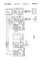
- FIG. 2is a block diagram of a power source and interface
- FIG. 3is a block diagram of a head end of a communication system according to the present invention.
- FIG. 4is a schematic representation of the multiplexing network
- FIG. 5shows pictorially the data base frequency range
- FIG. 6illustrates a power cable with integrated optical fiber
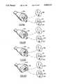
- FIG. 7Ais a plug according to the present invention.
- FIG 7Bis a receptacle according to the present invention.
- FIG. 7Cis a cross-sectional view of a plug-receptacle pair including receiving and transmitting means
- FIG. 7Dillustrates a plug which is provided with retroreflective means
- FIG. 7Eis an enlarged view of the retroreflector of FIG. 7D;
- FIGS. 8A, 8B, 8C and 8Dillustrate closed loop receptacles and mating plugs
- FIG. 9shows schematically a power supply to an appliance microprocessor
- FIG. 10is a perspective view of a switch according to the present invention.
- FIG. 10Aillustrates an alternate switch
- FIGS. 11A-11Cillustrates a sensor and remote signally means
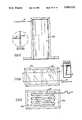
- FIG. 12illustrates an further application in accordance with the present invention.
- FIGS. 13,14, 14A and 15 and 15Aillustrate further embodiments of the invention.
- FIG. 1a simplified overview of the system according to the invention illustrates mains voltage 10 from the utility service introduced to the building (not shown) at the load centre 12.
- the load centre or power source meansis adapted to deliver 48 volts D.C. from a 48 V. DC converter 14.
- both of these voltagesare available for distribution over a pair of electrical power conductors included in the power distribution cables 16 shown in solid line in FIG. 1.
- Also included in the distribution cableis an optical fiber 18 shown in dotted line running in parallel with the electrical power conductors.
- the distribution cable 16interconnects the power source 12 to the control interface 20 from which the distribution cable 16 extends to a plurality of power receptacles 22.
- Each receptacle 22 connected to the control interface 20has in addition to a power delivery socket 24 a coupler 74 as best seen in FIG. 7C, capable of receiving a signal from the optical fiber 18 and transmitting a signal back to the optical fiber 18.
- the plug 26 mating with the socket 24 and attached to the appliance 28 for delivering power theretoalso may include a coupler 74 connected to an optical fiber 18 which runs in parallel with power conductors to the appliance.
- Appliances in accordance with the inventionmay be provided with a pre-programmed microprocessor (not shown) which includes operational data specific to the appliance. When an appliance 28 is plugged into the socket 24 the control interface 20 transmits via the optical fiber 18 a light wave interrogation signal to the microprocessor.
- the interrogation signalis processed by the microprocessor and in response thereto returns a light signal via the optical fiber 18, which signal includes operational data such as voltage requirements, current range, operating frequency and operating temperature.
- the control signal from the microprocessor in the appliance 28is assessed by the control interface 20 and if the data is within the specified conditions for that appliance the control interface 20 will, via the optical fiber 18, direct the power source 12 to provide the requested power to the appliance 28.
- the power source 12includes switch means 15 which in response to a command signal from the control interface 20 selects the appropriate power from the bank of available power ranges in the power source. Thus, if the appliance 28 calls for 48 volts DC the switch means 15 will connect the appliance 28 to the 48 volt DC power source.
- the receptacle 22is referred to throughout the description as being an outlet box of the type containing a socket, but the term is meant to cover other electrically connected devices which are permanently wired fixtures, such as lights.
- the systemmay include a single control interface, or a plurality of control interfaces, which are connected to a central control and distribution panel, may be used, depending on the power requirements of the building.
- appliances 30such as cooking stoves or clothes dryers have dedicated interfaces 32 which instruct the power source to deliver operational power responsive to an interrogation enquiry.
- FIG. 1also illustrates a service entrance 40 adapted to receive various external communication networks for distribution within the building. Included in the group of external communications for distribution within the building are telephone, CATV, and FM/AM radio.
- FIG. 2illustrates control interface units 20 in greater detail. 120 volt 60 Hz and 48 volt DC power is available for delivery to the control interface. Transmitting means 42 and receiving means 44 in the control interface continuously receive and transmit signals from the plug/receptacle pair to the power source and the power source delivers power to the receptacle/plug pair in response thereto.
- FIG. 3illustrates the communication distribution network in accordance with the invention.
- the external communication signals brought into the buildingmay be converted to digitized light signals and are distributed to receptacles via the optical fiber.
- the appliance connected to the receptacleis adapted to convert the optical signal to an electrical signal for processing by the appliance. It is to be understood that such appliances include telephone, radio, television and monitoring equipment.
- the optical fibercarries the communication signal, video, for example, and a command signal or information pertaining to the video signal i.e. to which receptacle the signal is to be directed and what channel is required.
- each applianceis provided with a microprocessor, which has stored in a permanent memory, operational information such as voltage, frequency, timing and current requirements.
- operational informationsuch as voltage, frequency, timing and current requirements.
- the microprocessorhas associated therewith a converter to convert the light signal to an electrical signal which is processed by the microprocessor.
- the microprocessorinstructs the converter to convert its electrical output to a light signal which is then relayed as operating data back to the interface via the optical fiber and this information is in turn communicated to the power distribution network.
- Power in accordance with the operational datais supplied to the appliance and continues to flow thereto until instructions are given to discontinue operation. Unplugging the appliance breaks the communication link provided by the optical fiber and the socket becomes deenergized. Similarly, a malfunction in the appliance will result in a communication signal which is outside of the operating range and this signal will instruct the power distribution network to cease power flow to the affected appliance. Similarly, communications in the form of cable television or telephone, etc. is available at the distribution panel and will be connected to the socket upon receipt of the appropriate instructions responsive to an interrogation signal fed to an appliance coupled to the socket. The interconnection of the communication and power sources are illustrated in FIGS. 2 through 4.
- FIG. 5illustrates the range of frequency used in the optical fiber communication link and which will accommodate the various communication requirements within the residents.
- the lower rangewhich may be 4800 bits per sec., for example, will be reserved for interrogation and reply communication respecting appliances and the higher ranges, which may be 90 megabits per sec., or even as high as 450 megabits per sec., will be reserved for external communication, audio, and video signals.
- FIG. 6is an illustration of one example of a power cable of the type which might be used in the closed loop programmable power system.
- the cable 16is shown as being flat in accordance with normal domestic wiring and includes an outer cover 61, internal insulation 62 and two insulated conductors 63.
- a ground wire 64is also shown.
- a single glass or plastic optical fiber 18is incorporated into the normal electrical wiring cable, this fiber being included at the time of manufacture. For certain special installations in which special requirements for the transmission of communication signals, more than one optical fiber may be included in the cable.
- the fiberis capable of withstanding temperature variations which are found in a residential environment.
- the fiberis also capable of being bent so as to be compatible with normal house wiring techniques.
- One technique which may be used to prevent the optical fiber from being bent too sharply when the cable is being drawn during installationis to include in the cable a continuous tube which has an internal diameter considerable larger than the outside diameter of the optical cable, and the optical cable is contained loosely in the tube.
- the plug/socket pair for use with the closed loop programmable systemis compatible with plugs and sockets currently in use.
- the only modification that is requiredinvolves the positioning of a centrally disposed opening in the body of the plug and socket to accommodate the optical fiber and the optical coupler in the mating faces.
- the lensmay be molded into the plastic portions of the socket and plug elements during manufacture.
- the fiberwhich is used in this application, has a small diameter 0.1 millimeters or less, it is necessary to incorporate optical couplers in the plug and socket pair to relieve tolerance requirements and to ensure proper communication coupling.
- a beam expanding lens 74compatible with the fiber cable 18 and the environment is secured to the end of one or both cables in the plug receptacle pair as shown in FIG. 7C.
- the lens systemreceives light exiting one of the fibers and directs it to the mating fiber. With the aid of such a coupling system, some mechanical tolerances are relaxed and a plug and socket pair analogous to those currently used in residential installations can be utilized without the need for elaborate aligning procedures.
- a collimating coupler lensso that there will be relatively low loss coupling between fibers, in spite of mechanical tolerances which are practical in the mating of a simple plug and socket combination.
- End to end coupling directly between bare fiber endsis relatively insensitive to tilt in the relative axis of the two fibers, but due to the small diameters of the fibers, such a coupling is very sensitive to lateral shifts.
- a feature of a mating plug and socketis that it is fairly controlled with respect to being angled, say 2° for an economical, but well designed, combination, but has a considerable amount of uncontrolled lateral shift, say 0.01" or 250 microns. Accordingly, the presence of a lens or lenses seems necessary to ensure the transmission of a signal through the connection formed by the plug and socket.
- the working lens radiusis the working lens radius
- fis the focal length of the lens
- NAis the numerical aperture, a measure of the angular spread of the light leaving a fiber
- f ⁇ NAis greater than 250 ⁇ is one condition, which prefers a large f.
- a relative tilt of the two coupler lenseswill result in a lateral shift of the one fiber core image overlapping the other fiber.
- This shiftis f ⁇ tilt and should be less than the fiber core radius for low loss.
- 62.5 micronsis a typical and commercially available optical fiber.
- fbe less than 30 ⁇ /0.03, or that
- the plug of an appliance without microprocessoris fitted with a retroreflective attachment 76 at the location which otherwise would be occupied by an optical coupler in a plug of a microprocessor equipped appliance as shown in FIG. 7D and this retroreflective material serves to reflect the interrogating signal provided by the interface back to the source.
- the reflected interrogation signalserves to notify the control interface that an appliance without facility to provide operational parameters has been connected to the system and the control interface will instruct the power source to provide the default power which will usually be 110 volts, 60 Hz. to the socket.
- the power sourcewhich will usually be 110 volts, 60 Hz. to the socket.
- the retroreflective material to be used on the appliance plugshould be capable of returning the incident light energy coaxially. Thus, light which might be reflected accidentally as from a mirror, reflecting magnetic surface, toys, etc. would not provide an error signal to the interface.
- One particularly efficient material for this purposeuses micropyramidal depressions of hexagonal form as illustrated in FIG. 7E although other configurations such as a microspheres reflector can be used.
- a selection of the size of the individual elements making up the reflective materialmay be calculated as described below.
- D1
- the normal working radius of the lensroughly speaking, is defined by the formula
- the focal length of the lensmay typically be 1 mm.
- the angular spread of the light leaving a fiberi.e., NA is approximately 0.2 or 0.3 for the type of fiber contemplated.
- D:1should be less than f ⁇ NA, or ##EQU1##
- the collimation imperfectionis due to the finite fiber core size, and
- the optical axis of the couplers in the plug and socketmay be slightly angled from a perpendicular to the plane surface of the plug and socket.
- any potentially reflecting material even placed flush against the plug facewould not be normal to the optical axis and would not return the incident energy.
- a universal socket 80has been designed.
- the socket as shown in FIG. 8A through Dincludes in addition to the optical coupler 74 an L shaped socket 82.
- FIGS. 8A, 8B, 8C and 8Dthe normal non closed loop power socket is shown immediately above the universal socket.
- the plug 86 on the leftis for an appliance requiring 48 volt DC. It can be seen that this plug will not mate with the non closed loop power socket 88 but that it will mate with the closed loop power socket 80.
- FIG. 8Billustrates a plug 26 which requires 110 volts and which is adapted for closed loop programmable power as evidenced by the optical coupler 74 in the front face.
- This plug 26will be received in both of the sockets 80, 88 on the right hand side.
- the plug 85 on the leftis for use by a 110 volt appliance which is not adapted for use with closed loop programmable power.
- Retroreflective surface 76 on the plug facereflects the interrogating signal back through the communicating fiber and the appliance will be provided with 110 volt supply.
- the socket as shown in FIGS. 8A to 8Dhas a L shaped opening to receive the distinguishing pin of the plugs it is to be understood that other configurations such as a right angled cross or a cross in which the arms of the cross are angled are contemplated by the invention.
- An appliance which is equipped with the programmed microprocessorwill require a low voltage DC supply in order to respond to the initial interrogating signal and to return information with respect to operational data. Since an important feature of closed loop programmable power is the safety feature associated with not having power at the socket until called for by an appliance, there is a requirement to generate low voltage power for the microprocessor before the main power is present.
- One of the techniques of satisfying this requirementis to superimpose a high frequency current limited AC voltage to the socket which provides a voltage to the plug when inserted. This high frequency AC voltage is then rectified by the circuit 90 shown in FIG. 9, the output 91, 92 being set at the DC voltage level required to operate the microprocessor in the appliance. Since the voltage is low, it does not pose a safety problem with respect to shock. Moreover, because the current is limited, fire hazard is not present.
- a low voltage current limited DC voltagecould be made available at the socket which would serve to power a microprocessor once the appliance plug is inserted in the socket.
- incident light energy derived from the interrogating signalcould supply a photovoltaic cell which would power a the microprocessor and external modulator in the appliance, the modulator, which may be in the form of a Kerr cell, would then act on the incoming and refected light so as to provide the light signal being returned to the interface.
- a power distribution cableincluding an integral optical fiber.
- a single length of the optical fibercan be used.
- an overhead lamp in a conventional applicationrequires that a power cable be run to the light socket and to a switch mounted on the wall in order to turn on and off the lamp.
- the power cableonly need be connected to the socket in as much as the control signal is delivered by the optical fiber to the control interface which will arrange for power to be provided to the lamp socket.
- the optical fibercan be inserted in the normal wall cavity, or since the optical fiber is of an extremely small diameter it could be unobtrusively placed on the surface of the wall.
- the optical fibercould be manufactured, for example, in combination with a very thin adhesive tape which could be applied directly to a wall face or other structural member.
- FIG. 10AA switch which comprises a retroreflective surface as described hereinbefore, operational between a first position adjacent the end of the cable and a second position removed from the cable will serve to provide the return communication to the interface is illustrated in FIG. 10A. While the switch 100 is in a first position wherein the retroreflective surface 76 is not in communication with the optical fiber 18, the overhead lamp will not be energized. In the second position wherein the optic retroreflective surface 76 is adjacent the end of the fiber 18 then the interrogation light will be reflected and a message directed to the interface to provide power to the overhead light. In order to increase reliability while keeping acceptable manufacturing tolerance, it is believed preferable to provide a lens at the end of the fiber through which the light signals are transmitted from and reflected to the optical fiber.
- a switchhas been developed which will serve to de-energize an appliance which otherwise is activated by the closed loop programmable power system.
- the communication fiber 18is severed and lens couplers 74 as described hereinbefore are placed on the two severed ends.
- a narrow air gapremains between the couplers and an opaque film 102 carried by a switch mechanism 104 is arranged to move through the gap.
- the opaque filmis in between the lens couplers 74, the interrogation signal will be disrupted and the appliance deactivated. Removal of the opaque film 102 from the coupler 74 will allow normal interrogating signal to be fed through the communication link and the appliance re-energized.
- the aspect of communicating command signals by means of an optical fiberalso applies to communicating externally generated communication information within the building.
- the optical fiber distributed to the receptacleseither in association with power distribution cables or individually may be used to transmit data such as audio and video signals, telephonic transmissions and monitoring information of various sources.
- each receptacleis capable of being accessed by a telephone set as well as the usual audio and video receivers.
- the communication signal which enters the building at the front endis coupled to communications converter means which converts the signal to a digitized or analog light signal.
- a devicesuch as a laser used in compact disc applications may be used.
- the light signal which has travelled through the optical fiberis converted to an electrical signal by means of photo diode type device.
- FIG. 11A further embodiment on this concept is illustrated in FIG. 11.
- power socketsare capable of providing external communication signals in addition to operational power.
- a televisionwhich is plugged into a closed loop programmable socket will initially receive the prescribed operating voltage and subsequently an audio and video signal selected from the appropriate inputs.
- the optical fiberis capable of simultaneously transmitting a range of digitized signals, it is possible to transmit externally generated command signals on the communication link in addition to the audio and video signals.
- FIGS. 1The configurations shown in FIGS.
- An adapter 110which may be plugged into the receptacle has a signal collecting device or detector 112 on the end opposite the plugs.
- the detectorwhich may be in the form of a silicon solar cell receives an infrared signal from a signal selection generator 114 (FIG. 11A) and the signal will be carried on the communication link to the interface where the signal will direct the appropriate TV signal to the requested socket.
- the signalis transmitted by an infrared light source such as a gallium arsenide light emitting diode
- the optical couplingcan also be completed by an optical fiber running directly from the signal selection generator 114 to the optical coupler of the receptacle.
- the detectormay be of an active nature in that it receives signals which are transmitted thereto in the form of sound, electrical or light and then converts them into digital or analog signals for transferring to the optical fiber
- the detectormay be more of a passive nature in that it is in the form of a lens or reflective surfaces, or both, for gathering light signals emitted from the generator and directing them to the coupler of the optical fiber in the receptacle (FIG. 11C).
- FIG. 12illustrates an optical fiber communication link carried by a gas delivery conduit. When coupled, the fiber optic communication link will interrogate the gas requirement of the gas operated appliance and will couple the operational data to the control panel.
- the optical fiber communication linkis also suitable for other forms of communication and monitoring services within a residence. For example, monitoring of room temperatures, child care and other health related conditions, smoke and heat detection for fire alarms, and various forms of intrusion detecting devices. Examples of intrusion detecting devices are shown in FIGS. 13, 14 and 15.
- a fiber optic 18is attached to the surface of a glass window 130.
- a reflective surface 132is provided at the end of the fiber and if the signal is returned no alarm will be sounded. If, however, the glass 130 is broken which disrupts the reflective surface 132, no signal will be returned to the interface and a command will be given to sound an alarm.
- a optical fiberis held adjacent to a reflective surface which is positioned by means of a wire 142 which passes in front of a window 130. If the wire 142 is disturbed, the angle of the reflector 140 is altered and the reflected signal through the communication link disrupted. This will result in an alarm being generated in response to a command from the interface as in the previous case.
- an optical fiber 18is secured adjacent to a reflective surface 150 at the edge of a door 152. If the door is opened by an intruder, the reflected signal will cease and the control interface 20 will command the appropriate alarm mechanism either within the building or at a remote monitor.
Landscapes
- Engineering & Computer Science (AREA)
- Physics & Mathematics (AREA)
- Power Engineering (AREA)
- General Physics & Mathematics (AREA)
- Optics & Photonics (AREA)
- Computer Networks & Wireless Communication (AREA)
- Signal Processing (AREA)
- Selective Calling Equipment (AREA)
- Connector Housings Or Holding Contact Members (AREA)
Abstract
Description
r=f×NA,
f×tanθ.sub.tilt <1/2 of 62.5 microns,
tan 2° 0.03.
f<1 mm.,
r=f×NA.
θ.sub.beam fiber radius/f.sub.lens
θ.sub.beam =30μ/1 mm., 0.03 radian, or about 2°.
λ/D.sub.=1 <0.03,
so,
D.sub.=1 >(λ/0.03=0.8μ/0.03 25).
Claims (24)
Applications Claiming Priority (2)
| Application Number | Priority Date | Filing Date | Title |
|---|---|---|---|
| CA542091 | 1987-07-13 | ||
| CA000542091ACA1297157C (en) | 1987-07-13 | 1987-07-13 | Closed loop, programmable power and communication system |
Publications (1)
| Publication Number | Publication Date |
|---|---|
| US5033112Atrue US5033112A (en) | 1991-07-16 |
Family
ID=4136077
Family Applications (1)
| Application Number | Title | Priority Date | Filing Date |
|---|---|---|---|
| US07/131,840Expired - LifetimeUS5033112A (en) | 1987-07-13 | 1987-12-11 | Closed loop, programmable power and communication system |
Country Status (2)
| Country | Link |
|---|---|
| US (1) | US5033112A (en) |
| CA (2) | CA1297157C (en) |
Cited By (69)
| Publication number | Priority date | Publication date | Assignee | Title |
|---|---|---|---|---|
| US5253068A (en)* | 1992-01-31 | 1993-10-12 | Crook Michael W | Gun shaped remote control unit for a television |
| US5289365A (en)* | 1991-12-23 | 1994-02-22 | Donnelly Corporation | Modular network control system |
| FR2696600A1 (en)* | 1992-10-06 | 1994-04-08 | Bourret Julien | Remote connection and disconnection of electric current appts. - uses optical fibre to detect proximity of electrical contacts to control remote switching of power |
| US5345592A (en)* | 1992-04-08 | 1994-09-06 | Concept W Systems, Inc. | Signal transfer and power delivery system for a television camera station |
| EP0556754A3 (en)* | 1992-02-18 | 1994-09-28 | Molex Inc | Automatically switched power receptacle |
| US5410292A (en)* | 1991-06-24 | 1995-04-25 | Sgs-Thomson Microelectronics S.A. | Method and system for communicating information within a dwelling or a property |
| EP0598520A3 (en)* | 1992-11-16 | 1995-07-26 | Gen Electric Co Plc | Consumption meter. |
| US5441047A (en)* | 1992-03-25 | 1995-08-15 | David; Daniel | Ambulatory patient health monitoring techniques utilizing interactive visual communication |
| GB2289140A (en)* | 1994-05-03 | 1995-11-08 | Methode Electronics Inc | Hybrid fibre optic/electrical connector |
| US5539388A (en) | 1993-02-11 | 1996-07-23 | National Digital Electronics, Inc. | Telemetry and control system |
| US5555015A (en)* | 1995-03-20 | 1996-09-10 | Intrinzix Technologies, Inc. | Wireless two way transmission between center and user stations via a relay |
| US5572438A (en)* | 1995-01-05 | 1996-11-05 | Teco Energy Management Services | Engery management and building automation system |
| US5579221A (en)* | 1993-12-31 | 1996-11-26 | Samsung Electronics Co., Ltd. | Home automation system having user controlled definition function |
| US5602670A (en)* | 1994-10-26 | 1997-02-11 | Rheem Manufacturing Company | Optical data receiver employing a solar cell resonant circuit and method for remote optical data communication |
| US5727208A (en)* | 1995-07-03 | 1998-03-10 | Dell U.S.A. L.P. | Method and apparatus for configuration of processor operating parameters |
| US5778116A (en)* | 1997-01-23 | 1998-07-07 | Tomich; John L. | Photonic home area network fiber/power insertion apparatus |
| EP0753774A3 (en)* | 1995-07-11 | 1998-08-05 | Gebrüder Merten GmbH & Co. KG | Electrical connection device |
| WO1998054843A1 (en)* | 1997-05-29 | 1998-12-03 | 3Com Corporation | Power transfer apparatus for concurrently transmitting data and power over data wires |
| US5924486A (en)* | 1997-10-29 | 1999-07-20 | Tecom, Inc. | Environmental condition control and energy management system and method |
| US5932933A (en)* | 1997-05-07 | 1999-08-03 | Matsushita Electric Industrial Co., Ltd. | Structure of power supply system |
| EP0825504A3 (en)* | 1996-08-23 | 1999-11-17 | Bosch-Siemens HausgerÀ¤te GmbH | Device for coupling an electrical household apparatus to a control system |
| US6012822A (en) | 1996-11-26 | 2000-01-11 | Robinson; William J. | Motion activated apparel flasher |
| GB2344469A (en)* | 1998-12-03 | 2000-06-07 | Delphi Tech Inc | Combined electrical and optical connector |
| US6097761A (en)* | 1997-02-11 | 2000-08-01 | U.S. Philips Corporation | Method and system for the transmission of data and power |
| EP0913748A3 (en)* | 1997-10-31 | 2001-03-21 | Hunter Douglas Industries B.V. | Group control system for light regulating devices |
| US20010025301A1 (en)* | 2000-02-09 | 2001-09-27 | Anderson Keith R. | Packet prioritization protocol for a large-scale, high speed computer network |
| US20020078290A1 (en)* | 2000-11-16 | 2002-06-20 | Derrico Joel Brian | Cluster computer network appliance |
| US20020161309A1 (en)* | 1999-10-27 | 2002-10-31 | Physiometrix, Inc. | Fiber optic power source for an electroencephalograph acquisition apparatus |
| US20030036819A1 (en)* | 1999-01-12 | 2003-02-20 | Amir Lehr | Data communication network |
| US20030200471A1 (en)* | 2002-04-23 | 2003-10-23 | Hitachi, Ltd. | Disk subsystem |
| US20040117330A1 (en)* | 2002-03-28 | 2004-06-17 | Ehlers Gregory A. | System and method for controlling usage of a commodity |
| US20050221816A1 (en)* | 2004-03-31 | 2005-10-06 | Hall Thomas M | System for and method of operating a radio station in a broadcast network |
| US20060056444A1 (en)* | 1998-07-28 | 2006-03-16 | Serconet, Ltd | Local area network of serial intelligent cells |
| US7072588B2 (en)* | 2000-10-03 | 2006-07-04 | Halliburton Energy Services, Inc. | Multiplexed distribution of optical power |
| US7072407B2 (en) | 2000-01-31 | 2006-07-04 | Brookline Flolmstead Llc | Combination power and full duplex data cable |
| US20070043478A1 (en)* | 2003-07-28 | 2007-02-22 | Ehlers Gregory A | System and method of controlling an HVAC system |
| US20070141869A1 (en)* | 2003-08-21 | 2007-06-21 | Hill-Rom Services, Inc. | Plug and receptacle having wired and wireless coupling |
| US20080104423A1 (en)* | 2006-10-31 | 2008-05-01 | Douglas Michael Boecker | Supplying combinations of clock frequency, voltage, and current to processors |
| US20080211321A1 (en)* | 2007-03-02 | 2008-09-04 | Billion Electric Co., Ltd. | Power adapter module with rotatable plug, power supply and electric apparatus with power adapter module or power supply of the same |
| US7447144B2 (en) | 2000-09-21 | 2008-11-04 | Serconet, Ltd. | Telephone communication system and method over local area network wiring |
| US7522615B2 (en) | 2002-11-13 | 2009-04-21 | Serconet, Ltd. | Addressable outlet, and a network using same |
| EP2128953A2 (en) | 2008-05-28 | 2009-12-02 | Hamilton Sundstrand Corporation | Electric power and control communications distribution system |
| US20100278537A1 (en)* | 2008-09-24 | 2010-11-04 | Elbex Video Ltd. | Method and Apparatus for Connecting AC Powered Switches, Current Sensors and Control Devices Via Two Way IR, Fiber Optic and Light Guide Cables |
| US7835386B2 (en) | 1999-07-07 | 2010-11-16 | Mosaid Technologies Incorporated | Local area network for distributing data communication, sensing and control signals |
| US20110130887A1 (en)* | 2002-03-28 | 2011-06-02 | Ehlers Sr Gregory Allen | Refrigeration monitor unit |
| WO2011079912A2 (en) | 2009-12-28 | 2011-07-07 | Fatum Projekt Ab | A system for power distribution and communication |
| US8045565B1 (en) | 2001-11-20 | 2011-10-25 | Brookline Flolmstead Llc | Method and apparatus for an environmentally hardened ethernet network system |
| US8103388B2 (en) | 2009-01-29 | 2012-01-24 | International Business Machines Corporation | System for prediction and communication of environmentally induced power useage limitation |
| USRE43163E1 (en) | 1999-05-14 | 2012-02-07 | Brookline Flolmstead Llc | High-speed network of independently linked nodes |
| US8155012B2 (en) | 1998-04-10 | 2012-04-10 | Chrimar Systems, Inc. | System and method for adapting a piece of terminal equipment |
| US8258973B2 (en) | 2005-02-11 | 2012-09-04 | Hill-Rom Services, Inc. | Transferable patient care equipment support |
| US8363797B2 (en) | 2000-03-20 | 2013-01-29 | Mosaid Technologies Incorporated | Telephone outlet for implementing a local area network over telephone lines and a local area network using such outlets |
| EP2499526A4 (en)* | 2009-11-11 | 2013-05-29 | Elbex Video Ltd | METHOD AND APPARATUS FOR OPTICAL SIGNAL COUPLING TO BOXED CIRCUITS THROUGH OPTICAL CABLES AND OPTICAL WAVEGUIDE COUPLERS |
| US20130268812A1 (en)* | 2010-11-15 | 2013-10-10 | Lifesafety Power, Inc. | Networked, Channelized Power Distribution, Monitor and Control for Security and Life Safety Applications |
| US8873586B2 (en) | 2000-04-19 | 2014-10-28 | Conversant Intellectual Property Management Incorporated | Network combining wired and non-wired segments |
| US20150228132A1 (en)* | 2014-02-11 | 2015-08-13 | Gentex Corporation | Systems and methods for adding a trainable transceiver to a vehicle |
| US9223336B2 (en) | 2011-05-17 | 2015-12-29 | 3M Innovative Properties Company | Remote socket apparatus |
| US9252418B2 (en) | 2011-03-09 | 2016-02-02 | Audi Ag | Battery for a vehicle and method of operating such a battery |
| WO2015187017A3 (en)* | 2014-06-05 | 2016-02-04 | Innovience International Bv | Solution for installing an in-house or in-building optical data network |
| US9343797B2 (en) | 2011-05-17 | 2016-05-17 | 3M Innovative Properties Company | Converged in-building network |
| GB2536194A (en)* | 2015-02-11 | 2016-09-14 | Eaton Ind France Sas | Automatically deducing the electrical cabling between electrical devices |
| JP2017037086A (en)* | 2012-10-26 | 2017-02-16 | エルベックスビデオ株式会社 | Method and device for calibrating intelligent ac outlet |
| US9948013B2 (en) | 2015-09-03 | 2018-04-17 | Steven D Houseworth | Modular electrical power transfer device for integrated power platform |
| EP3382824A4 (en)* | 2015-12-21 | 2018-11-21 | Huawei Technologies Co., Ltd. | Power adapter, socket and assembly |
| US10395769B2 (en) | 2015-12-16 | 2019-08-27 | Hill-Rom Services, Inc. | Patient care devices with local indication of correspondence and power line interconnectivity |
| US11032353B2 (en) | 2004-01-13 | 2021-06-08 | May Patents Ltd. | Information device |
| US12141007B2 (en) | 2022-07-11 | 2024-11-12 | Pure Storage, Inc. | Monitoring a power connection topology of a data center |
| US12186241B2 (en) | 2021-01-22 | 2025-01-07 | Hill-Rom Services, Inc. | Time-based wireless pairing between a medical device and a wall unit |
| US12279999B2 (en) | 2021-01-22 | 2025-04-22 | Hill-Rom Services, Inc. | Wireless configuration and authorization of a wall unit that pairs with a medical device |
Citations (34)
| Publication number | Priority date | Publication date | Assignee | Title |
|---|---|---|---|---|
| GB1429843A (en)* | 1973-06-02 | 1976-03-31 | Plessey Co Ltd | Endwise coupling of light guides |
| US4081208A (en)* | 1977-01-17 | 1978-03-28 | General Motors Corporation | Optical and electrical conduit termination means for circuit board |
| US4215276A (en)* | 1978-03-20 | 1980-07-29 | Janeway William F | Remote control of electrical power distribution system and method |
| CA1116714A (en)* | 1978-08-07 | 1982-01-19 | Robert S. Briggs, Jr. | Hotel/motel power load control and bilateral signalling apparatus |
| US4373777A (en)* | 1980-08-11 | 1983-02-15 | International Telephone And Telegraph Corporation | Connector and cable assembly |
| US4449043A (en)* | 1981-10-30 | 1984-05-15 | The United States Of America As Represented By The Secretary Of The Air Force | Optical power source control system |
| US4465333A (en)* | 1982-01-15 | 1984-08-14 | Grumman Aerospace Corporation | Electro-optical plug-in interconnection |
| CA1179032A (en)* | 1980-10-17 | 1984-12-04 | Lawrence G. Wiley | Coaxial cable/fiber optic bus network |
| US4491387A (en)* | 1977-05-13 | 1985-01-01 | Bicc Public Limited Company | Overhead electric and optical transmission systems |
| CA1190675A (en)* | 1981-07-28 | 1985-07-16 | Herbert Strehl | Wide-band communications system |
| JPS60157344A (en)* | 1984-01-26 | 1985-08-17 | Aichi Tokei Denki Co Ltd | signal transmission equipment |
| CA1192260A (en)* | 1981-09-04 | 1985-08-20 | Giok D. Khoe | Distribution system for a local area network |
| CA1194164A (en)* | 1980-07-30 | 1985-09-24 | George A. Waschka, Jr. | Local orderwire facility for fiber optic communication system |
| US4552432A (en)* | 1983-04-21 | 1985-11-12 | Cooper Industries, Inc. | Hybrid cable |
| CA1199074A (en)* | 1981-10-08 | 1986-01-07 | Bernhard Strebel | Communications network with optical channels |
| CA1199972A (en)* | 1981-10-21 | 1986-01-28 | Martin G. Hodgins | Data link using integrated optics devices |
| US4568145A (en)* | 1981-08-26 | 1986-02-04 | Les Cables De Lyon | Connection device for a cable incorporating optical fibers and metal conductors |
| CA1200844A (en)* | 1981-11-25 | 1986-02-18 | Alain P.M. Biolley | Digital information transmitting system through an optical transmission medium |
| CA1201170A (en)* | 1982-05-03 | 1986-02-25 | Simon Korowitz | Hybrid optical/electrical data highway |
| CA1201485A (en)* | 1981-11-25 | 1986-03-04 | Bernard C. De Loach, Jr. | Optical apparatus for interrogation of the status of a switch |
| CA1201484A (en)* | 1981-05-14 | 1986-03-04 | Douglas A. Pinnow | Information distribution system |
| CA1202081A (en)* | 1981-07-20 | 1986-03-18 | Gordon Gould | Optical communication system for drill hole logging |
| CA1208293A (en)* | 1983-12-09 | 1986-07-22 | Ansell W. Palmer | Sensing switch for a detachable communications probe |
| CA1210815A (en)* | 1982-12-22 | 1986-09-02 | Harold Blatter | Microprocessor self-turn-off arrangement for a consumer instrument |
| CA1210816A (en)* | 1982-12-22 | 1986-09-02 | Michael P. French | On-off arrangement in a microprocessor controlled remote transmitter for a consumer instrument |
| US4659176A (en)* | 1982-12-31 | 1987-04-21 | Kei Mori | Structure and implement for positioning the light-receiving edge of the light conductor onto the focus of the lens |
| CA1220848A (en)* | 1983-09-14 | 1987-04-21 | John R. Fox | Wideband cable network |
| US4690491A (en)* | 1985-10-04 | 1987-09-01 | Southwestern Bell Telephone | Building data transmission system |
| US4755792A (en)* | 1985-06-13 | 1988-07-05 | Black & Decker Inc. | Security control system |
| US4767181A (en)* | 1983-11-17 | 1988-08-30 | American Telephone And Telegraph Company | Electrical/lightwave connection arrangement |
| US4782322A (en)* | 1981-03-16 | 1988-11-01 | Transec Financiere S.A. | Amplitude modulation of control signals over electrical power lines utilizing the response of tuning fork filters |
| US4782482A (en)* | 1985-09-23 | 1988-11-01 | Alcatel Standard Electrica S.A. | Simultaneous voice and data communications system |
| US4803632A (en)* | 1986-05-09 | 1989-02-07 | Utility Systems Corporation | Intelligent utility meter system |
| US4808841A (en)* | 1986-11-12 | 1989-02-28 | Hitachi, Ltd. | Centralized control system for home electric appliances |
- 1987
- 1987-07-13CACA000542091Apatent/CA1297157C/ennot_activeExpired - Lifetime
- 1987-12-11USUS07/131,840patent/US5033112A/ennot_activeExpired - Lifetime
- 1990
- 1990-08-14CACA000615840Apatent/CA1309886C/ennot_activeExpired - Fee Related
Patent Citations (34)
| Publication number | Priority date | Publication date | Assignee | Title |
|---|---|---|---|---|
| GB1429843A (en)* | 1973-06-02 | 1976-03-31 | Plessey Co Ltd | Endwise coupling of light guides |
| US4081208A (en)* | 1977-01-17 | 1978-03-28 | General Motors Corporation | Optical and electrical conduit termination means for circuit board |
| US4491387A (en)* | 1977-05-13 | 1985-01-01 | Bicc Public Limited Company | Overhead electric and optical transmission systems |
| US4215276A (en)* | 1978-03-20 | 1980-07-29 | Janeway William F | Remote control of electrical power distribution system and method |
| CA1116714A (en)* | 1978-08-07 | 1982-01-19 | Robert S. Briggs, Jr. | Hotel/motel power load control and bilateral signalling apparatus |
| CA1194164A (en)* | 1980-07-30 | 1985-09-24 | George A. Waschka, Jr. | Local orderwire facility for fiber optic communication system |
| US4373777A (en)* | 1980-08-11 | 1983-02-15 | International Telephone And Telegraph Corporation | Connector and cable assembly |
| CA1179032A (en)* | 1980-10-17 | 1984-12-04 | Lawrence G. Wiley | Coaxial cable/fiber optic bus network |
| US4782322A (en)* | 1981-03-16 | 1988-11-01 | Transec Financiere S.A. | Amplitude modulation of control signals over electrical power lines utilizing the response of tuning fork filters |
| CA1201484A (en)* | 1981-05-14 | 1986-03-04 | Douglas A. Pinnow | Information distribution system |
| CA1202081A (en)* | 1981-07-20 | 1986-03-18 | Gordon Gould | Optical communication system for drill hole logging |
| CA1190675A (en)* | 1981-07-28 | 1985-07-16 | Herbert Strehl | Wide-band communications system |
| US4568145A (en)* | 1981-08-26 | 1986-02-04 | Les Cables De Lyon | Connection device for a cable incorporating optical fibers and metal conductors |
| CA1192260A (en)* | 1981-09-04 | 1985-08-20 | Giok D. Khoe | Distribution system for a local area network |
| CA1199074A (en)* | 1981-10-08 | 1986-01-07 | Bernhard Strebel | Communications network with optical channels |
| CA1199972A (en)* | 1981-10-21 | 1986-01-28 | Martin G. Hodgins | Data link using integrated optics devices |
| US4449043A (en)* | 1981-10-30 | 1984-05-15 | The United States Of America As Represented By The Secretary Of The Air Force | Optical power source control system |
| CA1200844A (en)* | 1981-11-25 | 1986-02-18 | Alain P.M. Biolley | Digital information transmitting system through an optical transmission medium |
| CA1201485A (en)* | 1981-11-25 | 1986-03-04 | Bernard C. De Loach, Jr. | Optical apparatus for interrogation of the status of a switch |
| US4465333A (en)* | 1982-01-15 | 1984-08-14 | Grumman Aerospace Corporation | Electro-optical plug-in interconnection |
| CA1201170A (en)* | 1982-05-03 | 1986-02-25 | Simon Korowitz | Hybrid optical/electrical data highway |
| CA1210815A (en)* | 1982-12-22 | 1986-09-02 | Harold Blatter | Microprocessor self-turn-off arrangement for a consumer instrument |
| CA1210816A (en)* | 1982-12-22 | 1986-09-02 | Michael P. French | On-off arrangement in a microprocessor controlled remote transmitter for a consumer instrument |
| US4659176A (en)* | 1982-12-31 | 1987-04-21 | Kei Mori | Structure and implement for positioning the light-receiving edge of the light conductor onto the focus of the lens |
| US4552432A (en)* | 1983-04-21 | 1985-11-12 | Cooper Industries, Inc. | Hybrid cable |
| CA1220848A (en)* | 1983-09-14 | 1987-04-21 | John R. Fox | Wideband cable network |
| US4767181A (en)* | 1983-11-17 | 1988-08-30 | American Telephone And Telegraph Company | Electrical/lightwave connection arrangement |
| CA1208293A (en)* | 1983-12-09 | 1986-07-22 | Ansell W. Palmer | Sensing switch for a detachable communications probe |
| JPS60157344A (en)* | 1984-01-26 | 1985-08-17 | Aichi Tokei Denki Co Ltd | signal transmission equipment |
| US4755792A (en)* | 1985-06-13 | 1988-07-05 | Black & Decker Inc. | Security control system |
| US4782482A (en)* | 1985-09-23 | 1988-11-01 | Alcatel Standard Electrica S.A. | Simultaneous voice and data communications system |
| US4690491A (en)* | 1985-10-04 | 1987-09-01 | Southwestern Bell Telephone | Building data transmission system |
| US4803632A (en)* | 1986-05-09 | 1989-02-07 | Utility Systems Corporation | Intelligent utility meter system |
| US4808841A (en)* | 1986-11-12 | 1989-02-28 | Hitachi, Ltd. | Centralized control system for home electric appliances |
Non-Patent Citations (10)
| Title |
|---|
| Closed Loop Programmable Power A Smart House Innovation John A. Edgar presented in Stockholm Jun. 1987.* |
| Closed Loop Programmable Power--A Smart House Innovation John A. Edgar--presented in Stockholm Jun. 1987. |
| Electrical Equipment News Mar. 1987, Smart House is Tops in Technology .* |
| Electrical Equipment News--Mar. 1987, "Smart House is Tops in Technology". |
| Electronics Jul. 1985, Will Smart House Provide Shelter for High Tech Firms* |
| Electronics--Jul. 1985, "Will Smart House Provide Shelter for High-Tech Firms?" |
| EPRI Journal Nov. 1986, "The Smart House: Wired for the Electronic Age". |
| EPRI Journal Nov. 1986, The Smart House: Wired for the Electronic Age .* |
| Professional Builder Dec. 1986, Smart House Most Revolutionary Change in Housing Since Indoor Plumbing .* |
| Professional Builder--Dec. 1986, "Smart House--Most Revolutionary Change in Housing Since Indoor Plumbing". |
Cited By (156)
| Publication number | Priority date | Publication date | Assignee | Title |
|---|---|---|---|---|
| US5410292A (en)* | 1991-06-24 | 1995-04-25 | Sgs-Thomson Microelectronics S.A. | Method and system for communicating information within a dwelling or a property |
| US5289365A (en)* | 1991-12-23 | 1994-02-22 | Donnelly Corporation | Modular network control system |
| US5253068A (en)* | 1992-01-31 | 1993-10-12 | Crook Michael W | Gun shaped remote control unit for a television |
| EP0556754A3 (en)* | 1992-02-18 | 1994-09-28 | Molex Inc | Automatically switched power receptacle |
| US5441047A (en)* | 1992-03-25 | 1995-08-15 | David; Daniel | Ambulatory patient health monitoring techniques utilizing interactive visual communication |
| US5345592A (en)* | 1992-04-08 | 1994-09-06 | Concept W Systems, Inc. | Signal transfer and power delivery system for a television camera station |
| FR2696600A1 (en)* | 1992-10-06 | 1994-04-08 | Bourret Julien | Remote connection and disconnection of electric current appts. - uses optical fibre to detect proximity of electrical contacts to control remote switching of power |
| EP0598520A3 (en)* | 1992-11-16 | 1995-07-26 | Gen Electric Co Plc | Consumption meter. |
| US5539388A (en) | 1993-02-11 | 1996-07-23 | National Digital Electronics, Inc. | Telemetry and control system |
| US5579221A (en)* | 1993-12-31 | 1996-11-26 | Samsung Electronics Co., Ltd. | Home automation system having user controlled definition function |
| GB2289140B (en)* | 1994-05-03 | 1998-02-18 | Methode Electronics Inc | Hybrid fiber optic/electrical connector |
| GB2289140A (en)* | 1994-05-03 | 1995-11-08 | Methode Electronics Inc | Hybrid fibre optic/electrical connector |
| US5602670A (en)* | 1994-10-26 | 1997-02-11 | Rheem Manufacturing Company | Optical data receiver employing a solar cell resonant circuit and method for remote optical data communication |
| US5684710A (en)* | 1995-01-05 | 1997-11-04 | Tecom Inc. | System for measuring electrical power interruptions |
| US5696695A (en)* | 1995-01-05 | 1997-12-09 | Tecom Inc. | System for rate-related control of electrical loads |
| US5572438A (en)* | 1995-01-05 | 1996-11-05 | Teco Energy Management Services | Engery management and building automation system |
| US5555015A (en)* | 1995-03-20 | 1996-09-10 | Intrinzix Technologies, Inc. | Wireless two way transmission between center and user stations via a relay |
| US5727208A (en)* | 1995-07-03 | 1998-03-10 | Dell U.S.A. L.P. | Method and apparatus for configuration of processor operating parameters |
| EP0753774A3 (en)* | 1995-07-11 | 1998-08-05 | Gebrüder Merten GmbH & Co. KG | Electrical connection device |
| EP0825504A3 (en)* | 1996-08-23 | 1999-11-17 | Bosch-Siemens HausgerÀ¤te GmbH | Device for coupling an electrical household apparatus to a control system |
| US6012822A (en) | 1996-11-26 | 2000-01-11 | Robinson; William J. | Motion activated apparel flasher |
| US5778116A (en)* | 1997-01-23 | 1998-07-07 | Tomich; John L. | Photonic home area network fiber/power insertion apparatus |
| EP0954763A4 (en)* | 1997-01-23 | 2001-05-23 | John L Tomich | Photonic home area network fiber/power insertion apparatus |
| US6097761A (en)* | 1997-02-11 | 2000-08-01 | U.S. Philips Corporation | Method and system for the transmission of data and power |
| US5932933A (en)* | 1997-05-07 | 1999-08-03 | Matsushita Electric Industrial Co., Ltd. | Structure of power supply system |
| US6496105B2 (en) | 1997-05-29 | 2002-12-17 | 3Com Corporation | Power transfer apparatus for concurrently transmitting data and power over data wires |
| US20040174251A1 (en)* | 1997-05-29 | 2004-09-09 | 3Com Corporation | Power transfer apparatus for concurrently transmitting data and power over data wires |
| US20040160312A1 (en)* | 1997-05-29 | 2004-08-19 | 3Com Corporation | Power transfer apparatus for concurrently transmitting data and power over data wires |
| US6140911A (en)* | 1997-05-29 | 2000-10-31 | 3Com Corporation | Power transfer apparatus for concurrently transmitting data and power over data wires |
| US6753761B2 (en)* | 1997-05-29 | 2004-06-22 | 3Com Corporation | Power transfer apparatus for concurrently transmitting data and power over data wires |
| US5994998A (en)* | 1997-05-29 | 1999-11-30 | 3Com Corporation | Power transfer apparatus for concurrently transmitting data and power over data wires |
| US7005969B2 (en) | 1997-05-29 | 2006-02-28 | Fisher David A | Power transfer apparatus for concurrently transmitting data and power over data wires |
| US6710704B2 (en)* | 1997-05-29 | 2004-03-23 | 3Com Corporation | Power transfer apparatus for concurrently transmitting data and power over data wires |
| US6329906B1 (en)* | 1997-05-29 | 2001-12-11 | 3Com Corporation | Power transfer apparatus for concurrently transmitting data and power over data wires |
| US20030062991A1 (en)* | 1997-05-29 | 2003-04-03 | 3Com Corporation | Power transfer apparatus for concurrently transmitting data and power over data wires |
| US20030058085A1 (en)* | 1997-05-29 | 2003-03-27 | 3Com Corporation | Power transfer apparatus for concurrently transmitting data and power over data wires |
| WO1998054843A1 (en)* | 1997-05-29 | 1998-12-03 | 3Com Corporation | Power transfer apparatus for concurrently transmitting data and power over data wires |
| US6216956B1 (en) | 1997-10-29 | 2001-04-17 | Tocom, Inc. | Environmental condition control and energy management system and method |
| US5924486A (en)* | 1997-10-29 | 1999-07-20 | Tecom, Inc. | Environmental condition control and energy management system and method |
| EP0913748A3 (en)* | 1997-10-31 | 2001-03-21 | Hunter Douglas Industries B.V. | Group control system for light regulating devices |
| US8902760B2 (en) | 1998-04-10 | 2014-12-02 | Chrimar Systems, Inc. | Network system and optional tethers |
| US8942107B2 (en) | 1998-04-10 | 2015-01-27 | Chrimar Systems, Inc. | Piece of ethernet terminal equipment |
| US9019838B2 (en) | 1998-04-10 | 2015-04-28 | Chrimar Systems, Inc. | Central piece of network equipment |
| US8155012B2 (en) | 1998-04-10 | 2012-04-10 | Chrimar Systems, Inc. | System and method for adapting a piece of terminal equipment |
| US9049019B2 (en) | 1998-04-10 | 2015-06-02 | Chrimar Systems, Inc. | Network equipment and optional tether |
| US9812825B2 (en) | 1998-04-10 | 2017-11-07 | Chrimar Systems, Inc. | Ethernet device |
| US8885659B2 (en) | 1998-07-28 | 2014-11-11 | Conversant Intellectual Property Management Incorporated | Local area network of serial intelligent cells |
| US7965735B2 (en) | 1998-07-28 | 2011-06-21 | Mosaid Technologies Incorporated | Local area network of serial intelligent cells |
| US8908673B2 (en) | 1998-07-28 | 2014-12-09 | Conversant Intellectual Property Management Incorporated | Local area network of serial intelligent cells |
| US7969917B2 (en) | 1998-07-28 | 2011-06-28 | Mosaid Technologies Incorporated | Local area network of serial intelligent cells |
| US8885660B2 (en) | 1998-07-28 | 2014-11-11 | Conversant Intellectual Property Management Incorporated | Local area network of serial intelligent cells |
| US8325636B2 (en) | 1998-07-28 | 2012-12-04 | Mosaid Technologies Incorporated | Local area network of serial intelligent cells |
| US7852874B2 (en) | 1998-07-28 | 2010-12-14 | Mosaid Technologies Incorporated | Local area network of serial intelligent cells |
| US8867523B2 (en) | 1998-07-28 | 2014-10-21 | Conversant Intellectual Property Management Incorporated | Local area network of serial intelligent cells |
| US7986708B2 (en) | 1998-07-28 | 2011-07-26 | Mosaid Technologies Incorporated | Local area network of serial intelligent cells |
| US20060056444A1 (en)* | 1998-07-28 | 2006-03-16 | Serconet, Ltd | Local area network of serial intelligent cells |
| US7830858B2 (en) | 1998-07-28 | 2010-11-09 | Mosaid Technologies Incorporated | Local area network of serial intelligent cells |
| GB2344469B (en)* | 1998-12-03 | 2002-07-10 | Delphi Tech Inc | Combined electrical and optical connector |
| GB2344469A (en)* | 1998-12-03 | 2000-06-07 | Delphi Tech Inc | Combined electrical and optical connector |
| US6985713B2 (en) | 1999-01-12 | 2006-01-10 | Powerdsine, Ltd. | Data communication network providing power over network connections with node identification functionality |
| US20030036819A1 (en)* | 1999-01-12 | 2003-02-20 | Amir Lehr | Data communication network |
| USRE43163E1 (en) | 1999-05-14 | 2012-02-07 | Brookline Flolmstead Llc | High-speed network of independently linked nodes |
| US8582598B2 (en) | 1999-07-07 | 2013-11-12 | Mosaid Technologies Incorporated | Local area network for distributing data communication, sensing and control signals |
| US7835386B2 (en) | 1999-07-07 | 2010-11-16 | Mosaid Technologies Incorporated | Local area network for distributing data communication, sensing and control signals |
| US8121132B2 (en) | 1999-07-07 | 2012-02-21 | Mosaid Technologies Incorporated | Local area network for distributing data communication, sensing and control signals |
| US20020161309A1 (en)* | 1999-10-27 | 2002-10-31 | Physiometrix, Inc. | Fiber optic power source for an electroencephalograph acquisition apparatus |
| US7072407B2 (en) | 2000-01-31 | 2006-07-04 | Brookline Flolmstead Llc | Combination power and full duplex data cable |
| US20070121634A1 (en)* | 2000-02-09 | 2007-05-31 | Brookline Flolmstead Llc | System and method for distributing addresses |
| US7835350B2 (en) | 2000-02-09 | 2010-11-16 | Anderson Keith R | Prioritizing data transmissions using the number of associated origin addresses |
| US20050249116A1 (en)* | 2000-02-09 | 2005-11-10 | Anderson Keith R | System and method for prioritizing data transmissions |
| US20010025301A1 (en)* | 2000-02-09 | 2001-09-27 | Anderson Keith R. | Packet prioritization protocol for a large-scale, high speed computer network |
| US6931003B2 (en) | 2000-02-09 | 2005-08-16 | Bookline Flolmstead Llc | Packet prioritization protocol for a large-scale, high speed computer network |
| US8855277B2 (en) | 2000-03-20 | 2014-10-07 | Conversant Intellectual Property Managment Incorporated | Telephone outlet for implementing a local area network over telephone lines and a local area network using such outlets |
| US8363797B2 (en) | 2000-03-20 | 2013-01-29 | Mosaid Technologies Incorporated | Telephone outlet for implementing a local area network over telephone lines and a local area network using such outlets |
| US8873586B2 (en) | 2000-04-19 | 2014-10-28 | Conversant Intellectual Property Management Incorporated | Network combining wired and non-wired segments |
| US8982904B2 (en) | 2000-04-19 | 2015-03-17 | Conversant Intellectual Property Management Inc. | Network combining wired and non-wired segments |
| US7489709B2 (en) | 2000-09-21 | 2009-02-10 | Serconet Ltd. | Telephone communication system and method over local area network wiring |
| US7480233B2 (en) | 2000-09-21 | 2009-01-20 | Serconet Ltd. | Telephone communication system and method over local area network wiring |
| US7447144B2 (en) | 2000-09-21 | 2008-11-04 | Serconet, Ltd. | Telephone communication system and method over local area network wiring |
| US8619538B2 (en) | 2000-09-21 | 2013-12-31 | Mosaid Technologies Incorporated | Communication system and method over local area network wiring |
| US8817779B2 (en) | 2000-09-21 | 2014-08-26 | Conversant Intellectual Property Management Incorporated | Telephone communication system and method over local area network wiring |
| US7843799B2 (en) | 2000-09-21 | 2010-11-30 | Mosaid Technologies Incorporated | Telephone communication system and method over local area network wiring |
| US7072588B2 (en)* | 2000-10-03 | 2006-07-04 | Halliburton Energy Services, Inc. | Multiplexed distribution of optical power |
| US20020078290A1 (en)* | 2000-11-16 | 2002-06-20 | Derrico Joel Brian | Cluster computer network appliance |
| US6948021B2 (en)* | 2000-11-16 | 2005-09-20 | Racemi Systems | Cluster component network appliance system and method for enhancing fault tolerance and hot-swapping |
| US8045565B1 (en) | 2001-11-20 | 2011-10-25 | Brookline Flolmstead Llc | Method and apparatus for an environmentally hardened ethernet network system |
| US7343226B2 (en) | 2002-03-28 | 2008-03-11 | Robertshaw Controls Company | System and method of controlling an HVAC system |
| US20110130887A1 (en)* | 2002-03-28 | 2011-06-02 | Ehlers Sr Gregory Allen | Refrigeration monitor unit |
| US7379997B2 (en) | 2002-03-28 | 2008-05-27 | Robertshaw Controls Company | System and method of controlling delivery and/or usage of a commodity |
| US20040138981A1 (en)* | 2002-03-28 | 2004-07-15 | Ehlers Gregory A | System and method of controlling delivery and/or usage of a commodity |
| US20040133314A1 (en)* | 2002-03-28 | 2004-07-08 | Ehlers Gregory A. | System and method of controlling an HVAC system |
| US20050033707A1 (en)* | 2002-03-28 | 2005-02-10 | Ehlers Gregory A. | Configurable architecture for controlling delivery and/or usage of a commodity |
| US20070043477A1 (en)* | 2002-03-28 | 2007-02-22 | Ehlers Gregory A | System and method of controlling an HVAC system |
| US20040117330A1 (en)* | 2002-03-28 | 2004-06-17 | Ehlers Gregory A. | System and method for controlling usage of a commodity |
| US20040139038A1 (en)* | 2002-03-28 | 2004-07-15 | Ehlers Gregory A. | System and method for controlling delivering of a commodity |
| US7418428B2 (en) | 2002-03-28 | 2008-08-26 | Robertshaw Controls Company | System and method for controlling delivering of a commodity |
| US7130719B2 (en) | 2002-03-28 | 2006-10-31 | Robertshaw Controls Company | System and method of controlling an HVAC system |
| US7516106B2 (en) | 2002-03-28 | 2009-04-07 | Robert Shaw Controls Company | System and method for controlling usage of a commodity |
| US20030200471A1 (en)* | 2002-04-23 | 2003-10-23 | Hitachi, Ltd. | Disk subsystem |
| US7047427B2 (en)* | 2002-04-23 | 2006-05-16 | Hitachi, Ltd. | Disk subsystem |
| US7522615B2 (en) | 2002-11-13 | 2009-04-21 | Serconet, Ltd. | Addressable outlet, and a network using same |
| US7990908B2 (en) | 2002-11-13 | 2011-08-02 | Mosaid Technologies Incorporated | Addressable outlet, and a network using the same |
| US8295185B2 (en) | 2002-11-13 | 2012-10-23 | Mosaid Technologies Inc. | Addressable outlet for use in wired local area network |
| US7911992B2 (en) | 2002-11-13 | 2011-03-22 | Mosaid Technologies Incorporated | Addressable outlet, and a network using the same |
| US20070043478A1 (en)* | 2003-07-28 | 2007-02-22 | Ehlers Gregory A | System and method of controlling an HVAC system |
| US9925104B2 (en) | 2003-08-21 | 2018-03-27 | Hill-Rom Services, Inc. | Hospital bed and room communication modules |
| US9572737B2 (en) | 2003-08-21 | 2017-02-21 | Hill-Rom Services, Inc. | Hospital bed having communication modules |
| US7399205B2 (en) | 2003-08-21 | 2008-07-15 | Hill-Rom Services, Inc. | Plug and receptacle having wired and wireless coupling |
| US10206837B2 (en) | 2003-08-21 | 2019-02-19 | Hill-Rom Services, Inc. | Hospital bed and room communication modules |
| US9142923B2 (en) | 2003-08-21 | 2015-09-22 | Hill-Rom Services, Inc. | Hospital bed having wireless data and locating capability |
| US20070141869A1 (en)* | 2003-08-21 | 2007-06-21 | Hill-Rom Services, Inc. | Plug and receptacle having wired and wireless coupling |
| US20110210833A1 (en)* | 2003-08-21 | 2011-09-01 | Mcneely Craig A | Combined power and data cord and receptacle |
| US8727804B2 (en) | 2003-08-21 | 2014-05-20 | Hill-Rom Services, Inc. | Combined power and data cord and receptacle |
| US11032353B2 (en) | 2004-01-13 | 2021-06-08 | May Patents Ltd. | Information device |
| US20050221816A1 (en)* | 2004-03-31 | 2005-10-06 | Hall Thomas M | System for and method of operating a radio station in a broadcast network |
| US8258973B2 (en) | 2005-02-11 | 2012-09-04 | Hill-Rom Services, Inc. | Transferable patient care equipment support |
| US7565560B2 (en)* | 2006-10-31 | 2009-07-21 | International Business Machines Corporation | Supplying combinations of clock frequency, voltage, and current to processors |
| US20080104423A1 (en)* | 2006-10-31 | 2008-05-01 | Douglas Michael Boecker | Supplying combinations of clock frequency, voltage, and current to processors |
| US20080211321A1 (en)* | 2007-03-02 | 2008-09-04 | Billion Electric Co., Ltd. | Power adapter module with rotatable plug, power supply and electric apparatus with power adapter module or power supply of the same |
| EP2128953A2 (en) | 2008-05-28 | 2009-12-02 | Hamilton Sundstrand Corporation | Electric power and control communications distribution system |
| US20090295551A1 (en)* | 2008-05-28 | 2009-12-03 | Dickey John A | Electric power and control communications distribution system |
| EP2128953A3 (en)* | 2008-05-28 | 2012-11-07 | Hamilton Sundstrand Corporation | Electric power and control communications distribution system |
| US20120183298A1 (en)* | 2008-09-24 | 2012-07-19 | Elbex Video Ltd. | Method and apparatus for connecting ac powered switches, current sensors and control devices via two way ir, fiber optic and light guide cables |
| US8175463B2 (en)* | 2008-09-24 | 2012-05-08 | Elbex Video Ltd. | Method and apparatus for connecting AC powered switches, current sensors and control devices via two way IR, fiber optic and light guide cables |
| US20120207481A1 (en)* | 2008-09-24 | 2012-08-16 | Elbex Video Ltd. | Method and apparatus for connecting ac powered switches, current sensors and control devices via two way ir, fiber optic and light guide cables |
| US8331794B2 (en)* | 2008-09-24 | 2012-12-11 | Elbex Video Ltd. | Method and apparatus for connecting AC powered switches, current sensors and control devices via two way IR, fiber optic and light guide cables |
| US20100278537A1 (en)* | 2008-09-24 | 2010-11-04 | Elbex Video Ltd. | Method and Apparatus for Connecting AC Powered Switches, Current Sensors and Control Devices Via Two Way IR, Fiber Optic and Light Guide Cables |
| US8331795B2 (en)* | 2008-09-24 | 2012-12-11 | Elbex Video Ltd. | Method and apparatus for connecting AC powered switches, current sensors and control devices via two way IR, fiber optic and light guide cables |
| US8103388B2 (en) | 2009-01-29 | 2012-01-24 | International Business Machines Corporation | System for prediction and communication of environmentally induced power useage limitation |
| EP2499526A4 (en)* | 2009-11-11 | 2013-05-29 | Elbex Video Ltd | METHOD AND APPARATUS FOR OPTICAL SIGNAL COUPLING TO BOXED CIRCUITS THROUGH OPTICAL CABLES AND OPTICAL WAVEGUIDE COUPLERS |
| US9054552B2 (en) | 2009-12-28 | 2015-06-09 | Zoliex Ab | System for power distribution and communication |
| WO2011079912A2 (en) | 2009-12-28 | 2011-07-07 | Fatum Projekt Ab | A system for power distribution and communication |
| US9952565B2 (en)* | 2010-11-15 | 2018-04-24 | Guang Liu | Networked, channelized power distribution, monitor and control for security and life safety applications |
| US20130268812A1 (en)* | 2010-11-15 | 2013-10-10 | Lifesafety Power, Inc. | Networked, Channelized Power Distribution, Monitor and Control for Security and Life Safety Applications |
| EP2684246B1 (en)* | 2011-03-09 | 2016-04-20 | Audi AG | Batterie for a vehicle and method for operating such a batterie |
| US9252418B2 (en) | 2011-03-09 | 2016-02-02 | Audi Ag | Battery for a vehicle and method of operating such a battery |
| US9343797B2 (en) | 2011-05-17 | 2016-05-17 | 3M Innovative Properties Company | Converged in-building network |
| US9223336B2 (en) | 2011-05-17 | 2015-12-29 | 3M Innovative Properties Company | Remote socket apparatus |
| JP2017037086A (en)* | 2012-10-26 | 2017-02-16 | エルベックスビデオ株式会社 | Method and device for calibrating intelligent ac outlet |
| US10859982B2 (en) | 2013-04-09 | 2020-12-08 | Lifesafety Power | Networked, channelized power distribution, monitor and control for security and life safety applications |
| US9640005B2 (en) | 2014-02-11 | 2017-05-02 | Gentex Corporation | Systems and methods for adding a trainable transceiver to a vehicle |
| US20150228132A1 (en)* | 2014-02-11 | 2015-08-13 | Gentex Corporation | Systems and methods for adding a trainable transceiver to a vehicle |
| US9947159B2 (en) | 2014-02-11 | 2018-04-17 | Gentex Corporation | Systems and methods for adding a trainable transceiver to a vehicle |
| US9984516B2 (en)* | 2014-02-11 | 2018-05-29 | Gentex Corporation | Systems and methods for adding a trainable transceiver to a vehicle |
| US10339741B2 (en) | 2014-02-11 | 2019-07-02 | Gentex Corporation | Systems and methods for adding a trainable transceiver to a vehicle |
| WO2015187017A3 (en)* | 2014-06-05 | 2016-02-04 | Innovience International Bv | Solution for installing an in-house or in-building optical data network |
| US10466424B2 (en) | 2014-06-05 | 2019-11-05 | Innovience International Bv | Solution for installing an in-house or in-building optical data network |
| US10535954B2 (en) | 2015-02-11 | 2020-01-14 | Eaton Intelligent Power Limited | Automatically deducing the electrical cabling between electrical devices |
| GB2536194A (en)* | 2015-02-11 | 2016-09-14 | Eaton Ind France Sas | Automatically deducing the electrical cabling between electrical devices |
| US9948013B2 (en) | 2015-09-03 | 2018-04-17 | Steven D Houseworth | Modular electrical power transfer device for integrated power platform |
| US10395769B2 (en) | 2015-12-16 | 2019-08-27 | Hill-Rom Services, Inc. | Patient care devices with local indication of correspondence and power line interconnectivity |
| EP3382824A4 (en)* | 2015-12-21 | 2018-11-21 | Huawei Technologies Co., Ltd. | Power adapter, socket and assembly |
| US10530102B2 (en) | 2015-12-21 | 2020-01-07 | Huawei Technologies Co., Ltd. | Power adapter, socket, and assembly |
| US12186241B2 (en) | 2021-01-22 | 2025-01-07 | Hill-Rom Services, Inc. | Time-based wireless pairing between a medical device and a wall unit |
| US12279999B2 (en) | 2021-01-22 | 2025-04-22 | Hill-Rom Services, Inc. | Wireless configuration and authorization of a wall unit that pairs with a medical device |
| US12141007B2 (en) | 2022-07-11 | 2024-11-12 | Pure Storage, Inc. | Monitoring a power connection topology of a data center |
Also Published As
| Publication number | Publication date |
|---|---|
| CA1297157C (en) | 1992-03-10 |
| CA1309886C (en) | 1992-11-10 |
Similar Documents
| Publication | Publication Date | Title |
|---|---|---|
| US5033112A (en) | Closed loop, programmable power and communication system | |
| JP4832617B1 (en) | Method and apparatus for connecting AC driven switches, current sensors and control devices via bi-directional IR, optical fiber and light guide cable | |
| US7035512B2 (en) | Method for providing a broadband infrastructure in a building by means of optical fibers | |
| CN104412541B (en) | Cable and Extender Units | |
| EP2210424B1 (en) | Method and apparatus for operating ac powered appliances via video interphones, two way ir drivers and remote control devices | |
| KR101469597B1 (en) | Method and apparatus for propagating optical signals along with power feed to illuminators and electrical appliances | |
| JP2011102979A (en) | Method and apparatus for coupling optical signal with packaged circuits via optical cables and lightguide couplers | |
| CN103503377A (en) | Method and apparatus for coding and linking electrical appliances for control and status report | |
| CA1312119C (en) | Optical shunt device | |
| US7082240B2 (en) | Home and building information system | |
| AU2001242955C1 (en) | A contact device and use of the same | |
| US11979196B2 (en) | Optical transmission power supply cable | |
| AU2001242955A1 (en) | A contact device and use of the same | |
| KR19990008284A (en) | Electrical plug device | |
| US20080152354A1 (en) | Fiber Optically Coupled Control System for Homes and Businesses | |
| JPH03235536A (en) | Optical output control system | |
| Bowling | Fiber in the home | |
| JPH04104621A (en) | Signal transmitter | |
| JPH0810074B2 (en) | Terminal equipment control device | |
| WO1990006025A1 (en) | Photoelectric connector and photo-outlet | |
| JPS63314610A (en) | Home control system | |
| HK1190239A (en) | Method and apparatus for combining ac power relay and current sensors with ac wiring devices | |
| JPS61232728A (en) | Outdoor plug socket unit | |
| HK1142467B (en) | Method and apparatus for operating ac powered appliances via video interphones, two way ir drivers and remote control devices | |
| HK1142467A (en) | Method and apparatus for operating ac powered appliances via video interphones, two way ir drivers and remote control devices |
Legal Events
| Date | Code | Title | Description |
|---|---|---|---|
| AS | Assignment | Owner name:NORTHERN TELECOM LIMITED, P.O. BOX 6123, STATION A Free format text:ASSIGNMENT OF ASSIGNORS INTEREST.;ASSIGNOR:GOODWIN, JOHN C.;REEL/FRAME:004852/0305 Effective date:19871021 Owner name:NORTHERN TELECOM LIMITED, CANADA Free format text:ASSIGNMENT OF ASSIGNORS INTEREST;ASSIGNOR:GOODWIN, JOHN C.;REEL/FRAME:004852/0305 Effective date:19871021 | |
| AS | Assignment | Owner name:BELL-NORTHERN RESEARCH LTD., P.O. BOX 3511, STATIO Free format text:ASSIGNMENT OF ASSIGNORS INTEREST.;ASSIGNOR:BOWLING, GEOFFREY N.;REEL/FRAME:004852/0303 Effective date:19871021 Owner name:BELL CANADA, 1050 BEAVER HALL HILL, MONTREAL, QUEB Free format text:ASSIGNMENT OF ASSIGNORS INTEREST.;ASSIGNOR:BELL-NORTHERN RESEARCH LTD.;REEL/FRAME:004852/0306 Effective date:19871021 Owner name:NORTHERN TELECOM LIMITED, P.O. BOX 6123, STATION A Free format text:ASSIGNMENT OF ASSIGNORS INTEREST.;ASSIGNOR:BELL CANADA;REEL/FRAME:004852/0307 Effective date:19871106 Owner name:BELL-NORTHERN RESEARCH LTD., CANADA Free format text:ASSIGNMENT OF ASSIGNORS INTEREST;ASSIGNOR:BOWLING, GEOFFREY N.;REEL/FRAME:004852/0303 Effective date:19871021 Owner name:BELL CANADA, CANADA Free format text:ASSIGNMENT OF ASSIGNORS INTEREST;ASSIGNOR:BELL-NORTHERN RESEARCH LTD.;REEL/FRAME:004852/0306 Effective date:19871021 Owner name:NORTHERN TELECOM LIMITED, CANADA Free format text:ASSIGNMENT OF ASSIGNORS INTEREST;ASSIGNOR:BELL CANADA;REEL/FRAME:004852/0307 Effective date:19871106 | |
| STCF | Information on status: patent grant | Free format text:PATENTED CASE | |
| FEPP | Fee payment procedure | Free format text:PAYOR NUMBER ASSIGNED (ORIGINAL EVENT CODE: ASPN); ENTITY STATUS OF PATENT OWNER: LARGE ENTITY | |
| FPAY | Fee payment | Year of fee payment:4 | |
| AS | Assignment | Owner name:NORDX/CDT, INC., CANADA Free format text:ASSIGNMENT OF ASSIGNORS INTEREST;ASSIGNOR:NORDX/CDT-IP CORP.;REEL/FRAME:008215/0514 Effective date:19960729 | |
| FEPP | Fee payment procedure | Free format text:PAYER NUMBER DE-ASSIGNED (ORIGINAL EVENT CODE: RMPN); ENTITY STATUS OF PATENT OWNER: LARGE ENTITY Free format text:PAYOR NUMBER ASSIGNED (ORIGINAL EVENT CODE: ASPN); ENTITY STATUS OF PATENT OWNER: LARGE ENTITY | |
| AS | Assignment | Owner name:NORDX/CDT, INC., CANADA Free format text:ASSIGNMENT OF ASSIGNORS INTEREST;ASSIGNOR:NORDX/CDT-IP CORP.;REEL/FRAME:008321/0082 Effective date:19960729 | |
| FPAY | Fee payment | Year of fee payment:8 | |
| FEPP | Fee payment procedure | Free format text:PAYOR NUMBER ASSIGNED (ORIGINAL EVENT CODE: ASPN); ENTITY STATUS OF PATENT OWNER: LARGE ENTITY Free format text:PAYER NUMBER DE-ASSIGNED (ORIGINAL EVENT CODE: RMPN); ENTITY STATUS OF PATENT OWNER: LARGE ENTITY | |
| FEPP | Fee payment procedure | Free format text:PAYER NUMBER DE-ASSIGNED (ORIGINAL EVENT CODE: RMPN); ENTITY STATUS OF PATENT OWNER: LARGE ENTITY Free format text:PAYOR NUMBER ASSIGNED (ORIGINAL EVENT CODE: ASPN); ENTITY STATUS OF PATENT OWNER: LARGE ENTITY | |
| FEPP | Fee payment procedure | Free format text:PAYOR NUMBER ASSIGNED (ORIGINAL EVENT CODE: ASPN); ENTITY STATUS OF PATENT OWNER: LARGE ENTITY Free format text:PAYER NUMBER DE-ASSIGNED (ORIGINAL EVENT CODE: RMPN); ENTITY STATUS OF PATENT OWNER: LARGE ENTITY | |
| FPAY | Fee payment | Year of fee payment:12 | |
| AS | Assignment | Owner name:FLEET NATIONAL BANK, MASSACHUSETTS Free format text:SECURITY INTEREST;ASSIGNORS:CABLE DESIGN TECHNOLOGIES CORPORATION;CABLE DESIGN TECHNOLOGIES INC. WASHINGTON CORPORATION;CDT INTERNATIONAL HOLDINGS INC.;AND OTHERS;REEL/FRAME:013362/0125 Effective date:20021024 | |
| REMI | Maintenance fee reminder mailed | ||
| AS | Assignment | Owner name:TENNECAST/CDT, INC. (THE TENNECAST COMPANY), OHIO Free format text:SECURITY TERMINATION AGREEMENT;ASSIGNOR:FLEET NATIONAL BANK;REEL/FRAME:016814/0396 Effective date:20030924 Owner name:NORDX/CDT CORP,, CANADA Free format text:SECURITY TERMINATION AGREEMENT;ASSIGNOR:FLEET NATIONAL BANK;REEL/FRAME:016814/0396 Effective date:20030924 Owner name:NORDX/CDT-IP CORP., CANADA Free format text:SECURITY TERMINATION AGREEMENT;ASSIGNOR:FLEET NATIONAL BANK;REEL/FRAME:016814/0396 Effective date:20030924 Owner name:RED HAWK/CDT, INC. (NETWORK ESSENTIALS, INC.), CAL Free format text:SECURITY TERMINATION AGREEMENT;ASSIGNOR:FLEET NATIONAL BANK;REEL/FRAME:016814/0396 Effective date:20030924 Owner name:X-MARK CDT, INC., PENNSYLVANIA Free format text:SECURITY TERMINATION AGREEMENT;ASSIGNOR:FLEET NATIONAL BANK;REEL/FRAME:016814/0396 Effective date:20030924 Owner name:CDT INTERNATIONAL HOLDINGS INC., UNITED KINGDOM Free format text:SECURITY TERMINATION AGREEMENT;ASSIGNOR:FLEET NATIONAL BANK;REEL/FRAME:016814/0396 Effective date:20030924 Owner name:DEARBORN/CDT, INC., ILLINOIS Free format text:SECURITY TERMINATION AGREEMENT;ASSIGNOR:FLEET NATIONAL BANK;REEL/FRAME:016814/0396 Effective date:20030924 Owner name:THERMAX/CDT, INC., CONNECTICUT Free format text:SECURITY TERMINATION AGREEMENT;ASSIGNOR:FLEET NATIONAL BANK;REEL/FRAME:016814/0396 Effective date:20030924 Owner name:A.W. INDUSTRIES, INC., FLORIDA Free format text:SECURITY TERMINATION AGREEMENT;ASSIGNOR:FLEET NATIONAL BANK;REEL/FRAME:016814/0396 Effective date:20030924 Owner name:CABLE DESIGN TECHNOLOGIES CORPORATION, PENNSYLVANI Free format text:SECURITY TERMINATION AGREEMENT;ASSIGNOR:FLEET NATIONAL BANK;REEL/FRAME:016814/0396 Effective date:20030924 Owner name:CABLE DESIGN TECHNOLOGIES, INC., MISSOURI Free format text:SECURITY TERMINATION AGREEMENT;ASSIGNOR:FLEET NATIONAL BANK;REEL/FRAME:016814/0396 Effective date:20030924 |