US5031370A - Coupled drive rods for installing ground anchors - Google Patents
Coupled drive rods for installing ground anchorsDownload PDFInfo
- Publication number
- US5031370A US5031370AUS07/535,560US53556090AUS5031370AUS 5031370 AUS5031370 AUS 5031370AUS 53556090 AUS53556090 AUS 53556090AUS 5031370 AUS5031370 AUS 5031370A
- Authority
- US
- United States
- Prior art keywords
- rods
- sleeve
- threads
- threaded
- rod
- Prior art date
- Legal status (The legal status is an assumption and is not a legal conclusion. Google has not performed a legal analysis and makes no representation as to the accuracy of the status listed.)
- Expired - Lifetime
Links
Images


Classifications
- E—FIXED CONSTRUCTIONS
- E02—HYDRAULIC ENGINEERING; FOUNDATIONS; SOIL SHIFTING
- E02D—FOUNDATIONS; EXCAVATIONS; EMBANKMENTS; UNDERGROUND OR UNDERWATER STRUCTURES
- E02D5/00—Bulkheads, piles, or other structural elements specially adapted to foundation engineering
- E02D5/74—Means for anchoring structural elements or bulkheads
- E02D5/80—Ground anchors
- Y—GENERAL TAGGING OF NEW TECHNOLOGICAL DEVELOPMENTS; GENERAL TAGGING OF CROSS-SECTIONAL TECHNOLOGIES SPANNING OVER SEVERAL SECTIONS OF THE IPC; TECHNICAL SUBJECTS COVERED BY FORMER USPC CROSS-REFERENCE ART COLLECTIONS [XRACs] AND DIGESTS
- Y10—TECHNICAL SUBJECTS COVERED BY FORMER USPC
- Y10T—TECHNICAL SUBJECTS COVERED BY FORMER US CLASSIFICATION
- Y10T403/00—Joints and connections
- Y10T403/57—Distinct end coupler
- Y10T403/5746—Continuous thread
Definitions
- This inventionrelates to the art of installing devices such as ground anchors in the ground and particularly deals with coupled drive rods or gads and methods for installing ground anchors wherein a string of drive rods are joined in end to end relation by devices which are not subjected to compression loads, but which hold the rods together in end to end relation under tension loads.
- drive rodsand “gads” include structures driven into the ground especially for installing ground anchors.
- ground anchors and the likeare installed by delivering impact blows to the anchors through a string of drive rods connected in end to end relation by couplers which are not subjected to impact blows or compression loads but which support tension loads.
- the drive rod unitsare relatively short so that their trailing ends can be impacted by a jackhammer or the like impacting device operated at ground level.
- the lead drive rodhas a onvex rounded leading end bottomed in the concave rounded bottom of an upright ground anchor socket to deliver the impact blows to the ground anchor without becoming fixedly attached to the socket.
- This lead rodhas a flat transverse trailing end and several turns of a smooth rolled external thread surround this trailing end.
- One or more intermediate drive rods having flat transverse ends and several turns of a smooth rolled external thread adjacent these endsare coupled in succession to the lead rod by couplers or sleeves which have several turns of an internal thread at both ends thereof separated by a central slide chamber. The threaded portions of the rods are threaded through and beyond the internal threads of the couplers so that the adjoining rod ends can slide in the chamber of the coupling and impact together during impact blows.
- the trailing drive rod of the stringhas a leading end like the intermediate rod sections to be threaded through the threaded end of the sleeve on the trailing end of the adjacent intermediate rod.
- this endmost rod of the drive rod stringis preferably equipped with a trailing shank for insertion in the bottom cup housing of a standard jackhammer and also has a radiating collar or flange to be engaged by the locking finger of the hammer.
- a drive rod or gad string kitpreferably also includes an extractor rod to replace the jackhammer driving shank rod in the event the driving rod string becomes locked in the ground and resists retraction by the jackhammer after the ground anchor has been installed to its desired depth.
- This extractor rodprovides an above ground member adapted to be engaged by an above ground pulling device.
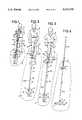
- FIGS. 1-4are schematic illustrations of the steps of installing ground anchors with drive rods or gads of this invention.
- FIG. 5is a cross-sectional view, with parts in elevation, along the line V--V of FIG. 1;
- FIG. 6is a front face view along the line VI--VI of the assembly of FIG. 5;
- FIG. 7is a longitudinal view of a string of drive rods or gads according to this invention.
- FIG. 8is a view along the line VIII--VIII of FIG. 7 showing the adjoining drive rods or gads under tension with the rod end separated;
- FIG. 9is a view similar to FIG. 8 taken along the line IX--IX of FIG. 7 and showing the adjacent drive rods under compression load with their adjoining ends abutted together;
- FIG. 10is a broken side elevational view of an elongated jackhammer shank rod for the drive rod string of this invention.
- FIG. 11is a view similar to FIG. 10 but illustrating a modified form of jackhammer shank rod of this invention
- FIG. 12is a broken elevational view of an intermediate drive rod or gad of this invention.
- FIG. 13is a broken elevational view of a lead drive rod of this invention.
- FIG. 14is an elevational view of a coupler of this invention illustrating the interior of the coupler in dotted lines;
- FIG. 15is a broken longitudinal view of an extractor rod to replace the jackhammer shank rods of FIGS. 10 and 11 when the string is stuck in the ground.
- FIGS. 1-4 of the drawingsillustrate the successive steps of installing a ground anchor according to this invention.
- a drive rod or gad string 10 of this inventiondrives an upright ground anchor A into the ground G by impact blows delivered from a jackhammer J held by an operator O standing on the ground G.
- the illustrated anchor Ais of the type disclosed and claimed in the David R. Chandler U.S. Pat. No. 4,802,317 issued Feb. 7, 1989, the disclosure of which is incorporated by reference into this application.
- the ground anchor Aas more particularly shown and described in the Chandler U.S. Pat. No. 4,802,317 is a plate-like member with a forwardly projecting leg L, laterally extending wings W, an open top socket S with a rounded bottom B and a trailing outturned rim R, all as shown in FIGS. 5 and 6.
- a rib on the front face of the plateswingably mounts a shackle or finger F into which is threaded the leading end of a pull rod P.R. to rotate the anchor A from its upright driving position of FIGS. 1-3 to its flatwise anchor position of FIG. 4.
- the drive rod or gad string 10 for the starting operationis initially composed of a lead rod section 11, a first sleeve or coupler 12 and a trailing jackhammer shank rod 13 slidably retained in the housing H of the jackhammer J by a retainer finger R.F.
- the forward end of the lead rod or gad 11is seated in the socket S of the anchor A.
- This anchoris in its upright or endwise position with the forward projecting leg L illustrated as entering into the ground G.
- the elongated pull rod P.R. as illustratedis threaded into the finger F of the anchor and draped over the shoulder of the operator O.
- This rod P.R.is sufficiently long to project above the ground G when the anchor is installed and rotated to its locking position as shown in FIG. 4 whereupon its projecting end may be coupled to a rod or guy wire G.W. for a utility pole or the like.
- the lead drive rod or gad 11 and the trailing jackhammer shank rod 13 coupled by the sleeve 1have a combined length which is short enough so that the jackhammer J driving the shank 13 will have its operating handles at a level to be conveniently grasped by the Operator O at about shoulder height when he is standing on the ground G for the start of the driving operation.
- the jackhammeris then operated to drive the anchor A into the ground for the full length of the lead drive rod or gad 11 whereupon the first coupler 12 will be adjacent ground level.
- the jackhammer shank rod 13is either removed from the coupling sleeve 12 or the coupling sleeve 12 is removed from the lead rod 10 and, as illustrated in FIG. 2, an intermediate coupling rod or gad 14 is coupled to the trailing end of the lead rod 11 through the coupler or sleeve 12 and the driving operation is repeated until the trailing end of this intermediate rod and the sleeve thereon is just above ground level.
- This operationis then followed up if necessary, by the addition of one or more intermediate drive rods 14 or gads as illustrated in FIG. 2 until the ground anchor A has reached the desired depth in the ground G.
- the pull rod P.R.follows the anchor.
- the jackhammer Jis conveniently grasped by the operator O at about knee level while his feet remain on the ground.
- the lengths of the component rods 11, 13 and 14 of the string 10are sufficiently short so that the operator of the jackhammer is always in a comfortable position.
- Convenient lengths for the component rodsare from two to three feet with the jackhammer shank rods being about 1-1/2 feet and the sleeves being about 8-10".
- the sleeves or couplers 12 of this inventionare metal tubes 15 with beveled ends 16 and have smooth, cylindrical bores 17 inwardly from these beveled ends 16.
- About two or three turns of an internal smooth rolled rope thread 18project into the bores 17 in spaced relation inwardly from the tapered ends 16. These threads 18 are followed by a continuation of the bores 17.
- the threadsare preferably left handed but can be of either hand.
- a reduced diameter bore 19 at the center of the sleeve 15is provided between the opposed bores 17.
- This reduced diameter bore 19provides a slide chamber for the ends of the drive rods or gads coupled together by the sleeve as will be hereinafter more fully described.
- the drive shank component 13 of the drive rod or gad string 10is a solid hardened steel rod with a trailing, preferably hexagonal, rod portion 20 projecting freely through the cup housing H of the jackhammer J with a flat transverse end 21 to be impacted by the conventional driving piston (not shown) of the jackhammer J.
- a radial collar or flange 22is provided between this hexagonal end portion 20 and a cylindrical rod portion 23. This collar or flange, as explained above, is engaged by the retaining finger R.F. of the jackhammer J to retain the rod member 13 in coupled relation with the jackhammer J while accommodating free reciprocation of the rod in the jackhammer for delivering the impact blows.
- the cylindrical portion 23 of the drive shank component forwardly of the collar or flange 22leads to a reduced diameter portion 24 on which is formed about two or three turns of an external smooth rolled rope thread 25 to mate with the internal threading of a coupler 12.
- a plain cylindrical portion 26 of the same diameter of the portion 24extends beyond the threads 25 and terminates in a flat transverse impacting end 27.
- the threads 25 of the rod member 13are threaded through and beyond the internal threads of the sleeve 12 so that the cylindrical portion 26 of the rod slides in the bore in the central portion of the sleeve.
- the flat end 27 of the rod member 13is thus slidably retained in the chamber provided by the bore 19 since the external threads 25 projecting beyond the internal threads 18 will prevent retraction from the sleeve 12 until the sleeve is rotated relative to the rod 13 to unthread the rod from the sleeve.
- a modified embodiment 13a of the jackhammer impact rodshown in FIG. 11, parts identical with the parts shown in FIG. 10 are marked with the same reference numerals. However, in the embodiment 13a, the rod is shorter and the reduced diameter cylindrical portion 24 has a further reduced diameter cylindrical portion 28 leading to the external threads 25.
- the three stage cylindrical portions 23, 24 and 28are useful in some installations where increased diameter impact rods are required.
- an intermediate rod component 14 in the string assembly 13is illustrated as having a hexagonal central portion 30 with reduced diameter cylindrical portions 31 projecting therefrom and leading to external threads 32 of greater diameter. These threads are also preferably about two or three turns of a smooth rolled rope-type thread and extend to cylindrical end portions 33 which terminate in flat transverse impact ends 34.
- the trailing end of the rod member 14is threaded through and beyond the threads 18 of the sleeve or coupler 12 with the cylindrical end portion 33 sliding in the bore 19 and with the impact end 34 opposing but spaced from the impact end 27 of the rod 13.
- FIG. 8illustrates that the assemblies of the rods 13 and 14 are under tension with ends 27 and 34 separated but coupled together by the sleeve 12.
- the illustrated components 14 of the string assembly 10are under compression load with their impact ends 34 in full abutting relation.
- the direction arrows of FIG. 9illustrate the compression force when the string assembly 10 is under impact loads from the jackhammer. It will be especially noted that the ends of the rods 14 within the sleeve 12 are free to slide in the sleeve because their threads 32 are beyond the threads 18 of the sleeve.
- the lead rod component 11may be hollow having a cylindrical bore 40 therethrough.
- This lead component 11preferably has a hexagonal central portion 41, and a cylindrical forward portion 42 leading to a convex rounded end portion 43.
- the portion 42fits freely in the socket S of the anchor A with the rounded convex bottom 43 seated on the concave bottom B of the socket.
- This arrangementprovides for delivery of the impact blows to the anchor A in axial alignment between the anchor and drive rods without permitting any mushrooming or enlargement of the end 43 into locked engagement with the socket S of the anchor. Therefore, the string 10 of drive rod components can be retracted from the anchor A by pulling up the jackhammer J as illustrated in FIG. 3.
- an extension rod component 50 shown in FIG. 15can replace the jackhammer impact rod 13.
- This retraction rodis a cylindrical rod member 51 with a diverging conical end 52 having an external thread 53 projecting therefrom for mating with the internal thread of the trailing sleeve or coupler 12 of the string 10.
- the cylindrical rod portion 51is of sufficient length so that it can be grasped bY a pulling tool above the ground to retract the string 10 out of the ground.
Landscapes
- Engineering & Computer Science (AREA)
- Structural Engineering (AREA)
- Life Sciences & Earth Sciences (AREA)
- General Life Sciences & Earth Sciences (AREA)
- Mining & Mineral Resources (AREA)
- Paleontology (AREA)
- Civil Engineering (AREA)
- General Engineering & Computer Science (AREA)
- Piles And Underground Anchors (AREA)
Abstract
Description
Claims (11)
Priority Applications (3)
| Application Number | Priority Date | Filing Date | Title |
|---|---|---|---|
| US07/535,560US5031370A (en) | 1990-06-11 | 1990-06-11 | Coupled drive rods for installing ground anchors |
| PCT/US1991/003554WO1991019860A1 (en) | 1990-06-11 | 1991-05-22 | Coupled drive rods for installing ground anchors |
| AU79973/91AAU7997391A (en) | 1990-06-11 | 1991-05-22 | Coupled drive rods for installing ground anchors |
Applications Claiming Priority (1)
| Application Number | Priority Date | Filing Date | Title |
|---|---|---|---|
| US07/535,560US5031370A (en) | 1990-06-11 | 1990-06-11 | Coupled drive rods for installing ground anchors |
Publications (1)
| Publication Number | Publication Date |
|---|---|
| US5031370Atrue US5031370A (en) | 1991-07-16 |
Family
ID=24134757
Family Applications (1)
| Application Number | Title | Priority Date | Filing Date |
|---|---|---|---|
| US07/535,560Expired - LifetimeUS5031370A (en) | 1990-06-11 | 1990-06-11 | Coupled drive rods for installing ground anchors |
Country Status (3)
| Country | Link |
|---|---|
| US (1) | US5031370A (en) |
| AU (1) | AU7997391A (en) |
| WO (1) | WO1991019860A1 (en) |
Cited By (73)
| Publication number | Priority date | Publication date | Assignee | Title |
|---|---|---|---|---|
| US5175966A (en)* | 1991-09-05 | 1993-01-05 | Better Bilt Products, Inc. | Earth anchor system |
| US5383749A (en)* | 1993-01-13 | 1995-01-24 | Reisdorff; Robert A. | Methods of reinforcing utility pole structures having their lower ends embedded in the ground, and reinforcement cage structure useful for practicing the method |
| US5625984A (en)* | 1995-03-07 | 1997-05-06 | Chapman; James P. | Ground anchor |
| US5649788A (en)* | 1994-09-14 | 1997-07-22 | Foresight Products, Inc. | Bi-directional anchor drive system and method of using same |
| US5881506A (en)* | 1995-03-07 | 1999-03-16 | Chapman; James P. | Ground anchor |
| US5888025A (en)* | 1994-11-25 | 1999-03-30 | Mai Pump Austria Gmbh | Coupling for tie rods |
| US6115988A (en)* | 1997-11-12 | 2000-09-12 | Laminated Wood Systems, Inc. | Methods of raising utility pole transmission hardware |
| US6151860A (en)* | 1997-11-12 | 2000-11-28 | Laminated Wood Systems | Methods of raising utility pole transmission cables |
| US6237289B1 (en)* | 1996-01-16 | 2001-05-29 | Foresight Products, Inc. | Ground Anchor |
| US20030056949A1 (en)* | 1998-12-07 | 2003-03-27 | Shell Oil Co. | Wellbore casing |
| US20030121219A1 (en)* | 2001-12-27 | 2003-07-03 | Dietel William R. | Apparatus for installing a workpiece below a surface |
| US20040033906A1 (en)* | 2001-07-27 | 2004-02-19 | Cook Robert Lance | Liner hanger with slip joint sealing members and method of use |
| US6742300B2 (en) | 2002-03-12 | 2004-06-01 | Andrew Sellers | System and method for anchoring a tree |
| US20040151608A1 (en)* | 2002-08-01 | 2004-08-05 | Vogt Gregory A. | High torque rotatable progressive cavity drive rods and connectors |
| US20040184088A1 (en)* | 1999-03-04 | 2004-09-23 | Panasonic Communications Co., Ltd. | Image data communication device and method |
| US20040215971A1 (en)* | 2001-08-29 | 2004-10-28 | Choong-Hee Nam | Anti keylog editor of activex base |
| US20040262014A1 (en)* | 1998-12-07 | 2004-12-30 | Cook Robert Lance | Mono-diameter wellbore casing |
| WO2004074622A3 (en)* | 2003-02-18 | 2005-03-31 | Enventure Global Technology | Protective compression and tension sleeves for threaded connections for radially expandable tubular members |
| US20050073196A1 (en)* | 2003-09-29 | 2005-04-07 | Yamaha Motor Co. Ltd. | Theft prevention system, theft prevention apparatus and power source controller for the system, transport vehicle including theft prevention system, and theft prevention method |
| US20050081358A1 (en)* | 1998-11-16 | 2005-04-21 | Cook Robert L. | Radial expansion of tubular members |
| US6983568B2 (en) | 2003-04-10 | 2006-01-10 | Chapman James P | Ground anchor |
| US7077211B2 (en) | 1998-12-07 | 2006-07-18 | Shell Oil Company | Method of creating a casing in a borehole |
| US7086475B2 (en) | 1998-12-07 | 2006-08-08 | Shell Oil Company | Method of inserting a tubular member into a wellbore |
| US7121352B2 (en) | 1998-11-16 | 2006-10-17 | Enventure Global Technology | Isolation of subterranean zones |
| US7146702B2 (en) | 2000-10-02 | 2006-12-12 | Shell Oil Company | Method and apparatus for forming a mono-diameter wellbore casing |
| US7147053B2 (en) | 1998-12-07 | 2006-12-12 | Shell Oil Company | Wellhead |
| US7159667B2 (en) | 1999-02-25 | 2007-01-09 | Shell Oil Company | Method of coupling a tubular member to a preexisting structure |
| US7168496B2 (en) | 2001-07-06 | 2007-01-30 | Eventure Global Technology | Liner hanger |
| US7172021B2 (en) | 2000-09-18 | 2007-02-06 | Shell Oil Company | Liner hanger with sliding sleeve valve |
| US7185710B2 (en) | 1998-12-07 | 2007-03-06 | Enventure Global Technology | Mono-diameter wellbore casing |
| US7231985B2 (en) | 1998-11-16 | 2007-06-19 | Shell Oil Company | Radial expansion of tubular members |
| US7234531B2 (en) | 1999-12-03 | 2007-06-26 | Enventure Global Technology, Llc | Mono-diameter wellbore casing |
| US7240728B2 (en) | 1998-12-07 | 2007-07-10 | Shell Oil Company | Expandable tubulars with a radial passage and wall portions with different wall thicknesses |
| US7243731B2 (en) | 2001-08-20 | 2007-07-17 | Enventure Global Technology | Apparatus for radially expanding tubular members including a segmented expansion cone |
| US7290605B2 (en) | 2001-12-27 | 2007-11-06 | Enventure Global Technology | Seal receptacle using expandable liner hanger |
| US7290616B2 (en) | 2001-07-06 | 2007-11-06 | Enventure Global Technology, L.L.C. | Liner hanger |
| US7308755B2 (en) | 2003-06-13 | 2007-12-18 | Shell Oil Company | Apparatus for forming a mono-diameter wellbore casing |
| US7325602B2 (en) | 2000-10-02 | 2008-02-05 | Shell Oil Company | Method and apparatus for forming a mono-diameter wellbore casing |
| US20080034682A1 (en)* | 2006-08-08 | 2008-02-14 | Carpenter Thomas J | Erosion control mat anchor system |
| US7350563B2 (en) | 1999-07-09 | 2008-04-01 | Enventure Global Technology, L.L.C. | System for lining a wellbore casing |
| US7360591B2 (en) | 2002-05-29 | 2008-04-22 | Enventure Global Technology, Llc | System for radially expanding a tubular member |
| US7363984B2 (en) | 1998-12-07 | 2008-04-29 | Enventure Global Technology, Llc | System for radially expanding a tubular member |
| US7377326B2 (en) | 2002-08-23 | 2008-05-27 | Enventure Global Technology, L.L.C. | Magnetic impulse applied sleeve method of forming a wellbore casing |
| US7383889B2 (en) | 2001-11-12 | 2008-06-10 | Enventure Global Technology, Llc | Mono diameter wellbore casing |
| US7398832B2 (en) | 2002-06-10 | 2008-07-15 | Enventure Global Technology, Llc | Mono-diameter wellbore casing |
| US7404444B2 (en) | 2002-09-20 | 2008-07-29 | Enventure Global Technology | Protective sleeve for expandable tubulars |
| US7410000B2 (en) | 2001-01-17 | 2008-08-12 | Enventure Global Technology, Llc. | Mono-diameter wellbore casing |
| US7416027B2 (en) | 2001-09-07 | 2008-08-26 | Enventure Global Technology, Llc | Adjustable expansion cone assembly |
| US7424918B2 (en) | 2002-08-23 | 2008-09-16 | Enventure Global Technology, L.L.C. | Interposed joint sealing layer method of forming a wellbore casing |
| US7438132B2 (en) | 1999-03-11 | 2008-10-21 | Shell Oil Company | Concentric pipes expanded at the pipe ends and method of forming |
| US7438133B2 (en) | 2003-02-26 | 2008-10-21 | Enventure Global Technology, Llc | Apparatus and method for radially expanding and plastically deforming a tubular member |
| US20090016826A1 (en)* | 2007-07-12 | 2009-01-15 | Carpenter Thomas J | Erosion control system |
| US7503393B2 (en) | 2003-01-27 | 2009-03-17 | Enventure Global Technology, Inc. | Lubrication system for radially expanding tubular members |
| US7513313B2 (en) | 2002-09-20 | 2009-04-07 | Enventure Global Technology, Llc | Bottom plug for forming a mono diameter wellbore casing |
| US7516790B2 (en) | 1999-12-03 | 2009-04-14 | Enventure Global Technology, Llc | Mono-diameter wellbore casing |
| US7552776B2 (en) | 1998-12-07 | 2009-06-30 | Enventure Global Technology, Llc | Anchor hangers |
| US7571774B2 (en) | 2002-09-20 | 2009-08-11 | Eventure Global Technology | Self-lubricating expansion mandrel for expandable tubular |
| US7603758B2 (en) | 1998-12-07 | 2009-10-20 | Shell Oil Company | Method of coupling a tubular member |
| US20090317190A1 (en)* | 2008-06-18 | 2009-12-24 | Carpenter Thomas J | Shoreline erosion control system |
| US20100058680A1 (en)* | 1993-11-03 | 2010-03-11 | Platipus Anchors Limited | Ground anchors |
| US7712522B2 (en) | 2003-09-05 | 2010-05-11 | Enventure Global Technology, Llc | Expansion cone and system |
| US7740076B2 (en) | 2002-04-12 | 2010-06-22 | Enventure Global Technology, L.L.C. | Protective sleeve for threaded connections for expandable liner hanger |
| US7739917B2 (en) | 2002-09-20 | 2010-06-22 | Enventure Global Technology, Llc | Pipe formability evaluation for expandable tubulars |
| US20100196102A1 (en)* | 2009-02-05 | 2010-08-05 | Carpenter Thomas J | Anchor system |
| US7775290B2 (en) | 2003-04-17 | 2010-08-17 | Enventure Global Technology, Llc | Apparatus for radially expanding and plastically deforming a tubular member |
| US7793721B2 (en) | 2003-03-11 | 2010-09-14 | Eventure Global Technology, Llc | Apparatus for radially expanding and plastically deforming a tubular member |
| NL2002773C2 (en)* | 2009-04-21 | 2010-10-22 | Kloosterman Waterbouw | ANCHOR DRIVER AND METHOD FOR USE THEREOF. |
| US7819185B2 (en) | 2004-08-13 | 2010-10-26 | Enventure Global Technology, Llc | Expandable tubular |
| US7886831B2 (en) | 2003-01-22 | 2011-02-15 | Enventure Global Technology, L.L.C. | Apparatus for radially expanding and plastically deforming a tubular member |
| US7918284B2 (en) | 2002-04-15 | 2011-04-05 | Enventure Global Technology, L.L.C. | Protective sleeve for threaded connections for expandable liner hanger |
| US20150021454A1 (en)* | 2013-03-12 | 2015-01-22 | Itzhak Sapir | Autonomous Remote Anchor System |
| US20160102442A1 (en)* | 2013-04-29 | 2016-04-14 | Gripple Limited | Ground anchor |
| US20250092628A1 (en)* | 2023-09-16 | 2025-03-20 | Hamed Niroumand | Space anchors for use on the moon, mars and other extraterrestrial bodies |
Citations (5)
| Publication number | Priority date | Publication date | Assignee | Title |
|---|---|---|---|---|
| US339534A (en)* | 1886-04-06 | John s | ||
| US1267250A (en)* | 1916-12-14 | 1918-05-21 | Thomas E Murray | Sheet-metal sleeve. |
| US3173524A (en)* | 1962-11-19 | 1965-03-16 | Earl J Redlich | Anchor |
| US4044513A (en)* | 1974-12-23 | 1977-08-30 | Foresight Industries | Earth anchor |
| US4802317A (en)* | 1987-10-29 | 1989-02-07 | Foresight Industries, Inc. | Ground anchor |
- 1990
- 1990-06-11USUS07/535,560patent/US5031370A/ennot_activeExpired - Lifetime
- 1991
- 1991-05-22WOPCT/US1991/003554patent/WO1991019860A1/enunknown
- 1991-05-22AUAU79973/91Apatent/AU7997391A/ennot_activeAbandoned
Patent Citations (5)
| Publication number | Priority date | Publication date | Assignee | Title |
|---|---|---|---|---|
| US339534A (en)* | 1886-04-06 | John s | ||
| US1267250A (en)* | 1916-12-14 | 1918-05-21 | Thomas E Murray | Sheet-metal sleeve. |
| US3173524A (en)* | 1962-11-19 | 1965-03-16 | Earl J Redlich | Anchor |
| US4044513A (en)* | 1974-12-23 | 1977-08-30 | Foresight Industries | Earth anchor |
| US4802317A (en)* | 1987-10-29 | 1989-02-07 | Foresight Industries, Inc. | Ground anchor |
Non-Patent Citations (2)
| Title |
|---|
| "Manta Ray" Equipment List and Installation Procedures Foresight Products, Inc. pamphlet. |
| Manta Ray Equipment List and Installation Procedures Foresight Products, Inc. pamphlet.* |
Cited By (111)
| Publication number | Priority date | Publication date | Assignee | Title |
|---|---|---|---|---|
| US5175966A (en)* | 1991-09-05 | 1993-01-05 | Better Bilt Products, Inc. | Earth anchor system |
| US5383749A (en)* | 1993-01-13 | 1995-01-24 | Reisdorff; Robert A. | Methods of reinforcing utility pole structures having their lower ends embedded in the ground, and reinforcement cage structure useful for practicing the method |
| US20100058680A1 (en)* | 1993-11-03 | 2010-03-11 | Platipus Anchors Limited | Ground anchors |
| US7713003B2 (en) | 1993-11-03 | 2010-05-11 | Platipus Anchors Limited | Ground anchors |
| US5649788A (en)* | 1994-09-14 | 1997-07-22 | Foresight Products, Inc. | Bi-directional anchor drive system and method of using same |
| US5888025A (en)* | 1994-11-25 | 1999-03-30 | Mai Pump Austria Gmbh | Coupling for tie rods |
| US5625984A (en)* | 1995-03-07 | 1997-05-06 | Chapman; James P. | Ground anchor |
| US5881506A (en)* | 1995-03-07 | 1999-03-16 | Chapman; James P. | Ground anchor |
| US6237289B1 (en)* | 1996-01-16 | 2001-05-29 | Foresight Products, Inc. | Ground Anchor |
| US6115988A (en)* | 1997-11-12 | 2000-09-12 | Laminated Wood Systems, Inc. | Methods of raising utility pole transmission hardware |
| US6151860A (en)* | 1997-11-12 | 2000-11-28 | Laminated Wood Systems | Methods of raising utility pole transmission cables |
| US7357190B2 (en) | 1998-11-16 | 2008-04-15 | Shell Oil Company | Radial expansion of tubular members |
| US7246667B2 (en) | 1998-11-16 | 2007-07-24 | Shell Oil Company | Radial expansion of tubular members |
| US7231985B2 (en) | 1998-11-16 | 2007-06-19 | Shell Oil Company | Radial expansion of tubular members |
| US7275601B2 (en) | 1998-11-16 | 2007-10-02 | Shell Oil Company | Radial expansion of tubular members |
| US7299881B2 (en) | 1998-11-16 | 2007-11-27 | Shell Oil Company | Radial expansion of tubular members |
| US7121352B2 (en) | 1998-11-16 | 2006-10-17 | Enventure Global Technology | Isolation of subterranean zones |
| US20050081358A1 (en)* | 1998-11-16 | 2005-04-21 | Cook Robert L. | Radial expansion of tubular members |
| US7363984B2 (en) | 1998-12-07 | 2008-04-29 | Enventure Global Technology, Llc | System for radially expanding a tubular member |
| US7195064B2 (en) | 1998-12-07 | 2007-03-27 | Enventure Global Technology | Mono-diameter wellbore casing |
| US7216701B2 (en) | 1998-12-07 | 2007-05-15 | Shell Oil Company | Apparatus for expanding a tubular member |
| US7434618B2 (en) | 1998-12-07 | 2008-10-14 | Shell Oil Company | Apparatus for expanding a tubular member |
| US7021390B2 (en) | 1998-12-07 | 2006-04-04 | Shell Oil Company | Tubular liner for wellbore casing |
| US7077211B2 (en) | 1998-12-07 | 2006-07-18 | Shell Oil Company | Method of creating a casing in a borehole |
| US7086475B2 (en) | 1998-12-07 | 2006-08-08 | Shell Oil Company | Method of inserting a tubular member into a wellbore |
| US7108061B2 (en) | 1998-12-07 | 2006-09-19 | Shell Oil Company | Expander for a tapered liner with a shoe |
| US7121337B2 (en) | 1998-12-07 | 2006-10-17 | Shell Oil Company | Apparatus for expanding a tubular member |
| US20040262014A1 (en)* | 1998-12-07 | 2004-12-30 | Cook Robert Lance | Mono-diameter wellbore casing |
| US7350564B2 (en) | 1998-12-07 | 2008-04-01 | Enventure Global Technology, L.L.C. | Mono-diameter wellbore casing |
| US7147053B2 (en) | 1998-12-07 | 2006-12-12 | Shell Oil Company | Wellhead |
| US7552776B2 (en) | 1998-12-07 | 2009-06-30 | Enventure Global Technology, Llc | Anchor hangers |
| US7357188B1 (en) | 1998-12-07 | 2008-04-15 | Shell Oil Company | Mono-diameter wellbore casing |
| US7603758B2 (en) | 1998-12-07 | 2009-10-20 | Shell Oil Company | Method of coupling a tubular member |
| US7665532B2 (en) | 1998-12-07 | 2010-02-23 | Shell Oil Company | Pipeline |
| US7174964B2 (en) | 1998-12-07 | 2007-02-13 | Shell Oil Company | Wellhead with radially expanded tubulars |
| US7240728B2 (en) | 1998-12-07 | 2007-07-10 | Shell Oil Company | Expandable tubulars with a radial passage and wall portions with different wall thicknesses |
| US20030056949A1 (en)* | 1998-12-07 | 2003-03-27 | Shell Oil Co. | Wellbore casing |
| US7185710B2 (en) | 1998-12-07 | 2007-03-06 | Enventure Global Technology | Mono-diameter wellbore casing |
| US7195061B2 (en) | 1998-12-07 | 2007-03-27 | Shell Oil Company | Apparatus for expanding a tubular member |
| US7419009B2 (en) | 1998-12-07 | 2008-09-02 | Shell Oil Company | Apparatus for radially expanding and plastically deforming a tubular member |
| US7198100B2 (en) | 1998-12-07 | 2007-04-03 | Shell Oil Company | Apparatus for expanding a tubular member |
| US7240729B2 (en) | 1998-12-07 | 2007-07-10 | Shell Oil Company | Apparatus for expanding a tubular member |
| US7159667B2 (en) | 1999-02-25 | 2007-01-09 | Shell Oil Company | Method of coupling a tubular member to a preexisting structure |
| US7556092B2 (en) | 1999-02-26 | 2009-07-07 | Enventure Global Technology, Llc | Flow control system for an apparatus for radially expanding tubular members |
| US20040184088A1 (en)* | 1999-03-04 | 2004-09-23 | Panasonic Communications Co., Ltd. | Image data communication device and method |
| US7438132B2 (en) | 1999-03-11 | 2008-10-21 | Shell Oil Company | Concentric pipes expanded at the pipe ends and method of forming |
| US7350563B2 (en) | 1999-07-09 | 2008-04-01 | Enventure Global Technology, L.L.C. | System for lining a wellbore casing |
| US7234531B2 (en) | 1999-12-03 | 2007-06-26 | Enventure Global Technology, Llc | Mono-diameter wellbore casing |
| US7516790B2 (en) | 1999-12-03 | 2009-04-14 | Enventure Global Technology, Llc | Mono-diameter wellbore casing |
| US7172021B2 (en) | 2000-09-18 | 2007-02-06 | Shell Oil Company | Liner hanger with sliding sleeve valve |
| US7201223B2 (en) | 2000-10-02 | 2007-04-10 | Shell Oil Company | Method and apparatus for forming a mono-diameter wellbore casing |
| US7172019B2 (en) | 2000-10-02 | 2007-02-06 | Shell Oil Company | Method and apparatus for forming a mono-diameter wellbore casing |
| US7146702B2 (en) | 2000-10-02 | 2006-12-12 | Shell Oil Company | Method and apparatus for forming a mono-diameter wellbore casing |
| US7363690B2 (en) | 2000-10-02 | 2008-04-29 | Shell Oil Company | Method and apparatus for forming a mono-diameter wellbore casing |
| US7325602B2 (en) | 2000-10-02 | 2008-02-05 | Shell Oil Company | Method and apparatus for forming a mono-diameter wellbore casing |
| US7204007B2 (en) | 2000-10-02 | 2007-04-17 | Shell Oil Company | Method and apparatus for forming a mono-diameter wellbore casing |
| US7363691B2 (en) | 2000-10-02 | 2008-04-29 | Shell Oil Company | Method and apparatus for forming a mono-diameter wellbore casing |
| US7410000B2 (en) | 2001-01-17 | 2008-08-12 | Enventure Global Technology, Llc. | Mono-diameter wellbore casing |
| US7290616B2 (en) | 2001-07-06 | 2007-11-06 | Enventure Global Technology, L.L.C. | Liner hanger |
| US7168496B2 (en) | 2001-07-06 | 2007-01-30 | Eventure Global Technology | Liner hanger |
| US20040033906A1 (en)* | 2001-07-27 | 2004-02-19 | Cook Robert Lance | Liner hanger with slip joint sealing members and method of use |
| US7258168B2 (en) | 2001-07-27 | 2007-08-21 | Enventure Global Technology L.L.C. | Liner hanger with slip joint sealing members and method of use |
| US7243731B2 (en) | 2001-08-20 | 2007-07-17 | Enventure Global Technology | Apparatus for radially expanding tubular members including a segmented expansion cone |
| US20040215971A1 (en)* | 2001-08-29 | 2004-10-28 | Choong-Hee Nam | Anti keylog editor of activex base |
| US7416027B2 (en) | 2001-09-07 | 2008-08-26 | Enventure Global Technology, Llc | Adjustable expansion cone assembly |
| US7559365B2 (en) | 2001-11-12 | 2009-07-14 | Enventure Global Technology, Llc | Collapsible expansion cone |
| US7383889B2 (en) | 2001-11-12 | 2008-06-10 | Enventure Global Technology, Llc | Mono diameter wellbore casing |
| US7290605B2 (en) | 2001-12-27 | 2007-11-06 | Enventure Global Technology | Seal receptacle using expandable liner hanger |
| US20030121219A1 (en)* | 2001-12-27 | 2003-07-03 | Dietel William R. | Apparatus for installing a workpiece below a surface |
| US6742300B2 (en) | 2002-03-12 | 2004-06-01 | Andrew Sellers | System and method for anchoring a tree |
| US7740076B2 (en) | 2002-04-12 | 2010-06-22 | Enventure Global Technology, L.L.C. | Protective sleeve for threaded connections for expandable liner hanger |
| US7918284B2 (en) | 2002-04-15 | 2011-04-05 | Enventure Global Technology, L.L.C. | Protective sleeve for threaded connections for expandable liner hanger |
| US7360591B2 (en) | 2002-05-29 | 2008-04-22 | Enventure Global Technology, Llc | System for radially expanding a tubular member |
| US7398832B2 (en) | 2002-06-10 | 2008-07-15 | Enventure Global Technology, Llc | Mono-diameter wellbore casing |
| US20040151608A1 (en)* | 2002-08-01 | 2004-08-05 | Vogt Gregory A. | High torque rotatable progressive cavity drive rods and connectors |
| US7377326B2 (en) | 2002-08-23 | 2008-05-27 | Enventure Global Technology, L.L.C. | Magnetic impulse applied sleeve method of forming a wellbore casing |
| US7424918B2 (en) | 2002-08-23 | 2008-09-16 | Enventure Global Technology, L.L.C. | Interposed joint sealing layer method of forming a wellbore casing |
| US7404444B2 (en) | 2002-09-20 | 2008-07-29 | Enventure Global Technology | Protective sleeve for expandable tubulars |
| US7571774B2 (en) | 2002-09-20 | 2009-08-11 | Eventure Global Technology | Self-lubricating expansion mandrel for expandable tubular |
| US7739917B2 (en) | 2002-09-20 | 2010-06-22 | Enventure Global Technology, Llc | Pipe formability evaluation for expandable tubulars |
| US7513313B2 (en) | 2002-09-20 | 2009-04-07 | Enventure Global Technology, Llc | Bottom plug for forming a mono diameter wellbore casing |
| US7886831B2 (en) | 2003-01-22 | 2011-02-15 | Enventure Global Technology, L.L.C. | Apparatus for radially expanding and plastically deforming a tubular member |
| US7503393B2 (en) | 2003-01-27 | 2009-03-17 | Enventure Global Technology, Inc. | Lubrication system for radially expanding tubular members |
| GB2429224B (en)* | 2003-02-18 | 2007-11-28 | Enventure Global Technology | Protective compression and tension sleeves for threaded connections for radially expandable tubular members |
| GB2429224A (en)* | 2003-02-18 | 2007-02-21 | Enventure Global Technology | Expandable tubular joint with increased axial loading capacity |
| WO2004074622A3 (en)* | 2003-02-18 | 2005-03-31 | Enventure Global Technology | Protective compression and tension sleeves for threaded connections for radially expandable tubular members |
| GB2429225A (en)* | 2003-02-18 | 2007-02-21 | Enventure Global Technology | Expandable tubular joint with overlapping frangible sleeve |
| GB2429225B (en)* | 2003-02-18 | 2007-11-28 | Enventure Global Technology | Protective sleeves with sacrificial material-filled reliefs for threaded connections of radially expandable tubular members |
| GB2415003A (en)* | 2003-02-18 | 2005-12-14 | Enventure Global Technology | Protective compression and tension sleeves for threaded connections for radially expandable tubular members |
| GB2415003B (en)* | 2003-02-18 | 2007-06-20 | Enventure Global Technology | Protective compression and tension sleeves for threaded connections for radially expandable tubular members |
| US7438133B2 (en) | 2003-02-26 | 2008-10-21 | Enventure Global Technology, Llc | Apparatus and method for radially expanding and plastically deforming a tubular member |
| US7793721B2 (en) | 2003-03-11 | 2010-09-14 | Eventure Global Technology, Llc | Apparatus for radially expanding and plastically deforming a tubular member |
| US6983568B2 (en) | 2003-04-10 | 2006-01-10 | Chapman James P | Ground anchor |
| US7775290B2 (en) | 2003-04-17 | 2010-08-17 | Enventure Global Technology, Llc | Apparatus for radially expanding and plastically deforming a tubular member |
| US7308755B2 (en) | 2003-06-13 | 2007-12-18 | Shell Oil Company | Apparatus for forming a mono-diameter wellbore casing |
| US7712522B2 (en) | 2003-09-05 | 2010-05-11 | Enventure Global Technology, Llc | Expansion cone and system |
| US20050073196A1 (en)* | 2003-09-29 | 2005-04-07 | Yamaha Motor Co. Ltd. | Theft prevention system, theft prevention apparatus and power source controller for the system, transport vehicle including theft prevention system, and theft prevention method |
| US7819185B2 (en) | 2004-08-13 | 2010-10-26 | Enventure Global Technology, Llc | Expandable tubular |
| US20080034682A1 (en)* | 2006-08-08 | 2008-02-14 | Carpenter Thomas J | Erosion control mat anchor system |
| US7862259B2 (en)* | 2006-08-08 | 2011-01-04 | Erosion Tech, Llc | Erosion control mat anchor system |
| US20090016826A1 (en)* | 2007-07-12 | 2009-01-15 | Carpenter Thomas J | Erosion control system |
| US7828499B2 (en) | 2007-07-12 | 2010-11-09 | Erosion Tech, Llc | Erosion control system |
| US7695219B2 (en) | 2008-06-18 | 2010-04-13 | Erosion Tech, Llc | Shoreline erosion control system |
| US20090317190A1 (en)* | 2008-06-18 | 2009-12-24 | Carpenter Thomas J | Shoreline erosion control system |
| US20100196102A1 (en)* | 2009-02-05 | 2010-08-05 | Carpenter Thomas J | Anchor system |
| US8157482B2 (en) | 2009-02-05 | 2012-04-17 | Erosion Tech, Llc | Anchor system |
| NL2002773C2 (en)* | 2009-04-21 | 2010-10-22 | Kloosterman Waterbouw | ANCHOR DRIVER AND METHOD FOR USE THEREOF. |
| US20150021454A1 (en)* | 2013-03-12 | 2015-01-22 | Itzhak Sapir | Autonomous Remote Anchor System |
| US20160102442A1 (en)* | 2013-04-29 | 2016-04-14 | Gripple Limited | Ground anchor |
| US9624639B2 (en)* | 2013-04-29 | 2017-04-18 | Gripple Limited | Ground anchor |
| US20250092628A1 (en)* | 2023-09-16 | 2025-03-20 | Hamed Niroumand | Space anchors for use on the moon, mars and other extraterrestrial bodies |
Also Published As
| Publication number | Publication date |
|---|---|
| WO1991019860A1 (en) | 1991-12-26 |
| AU7997391A (en) | 1992-01-07 |
Similar Documents
| Publication | Publication Date | Title |
|---|---|---|
| US5031370A (en) | Coupled drive rods for installing ground anchors | |
| US7407021B2 (en) | Methods for the installation of earth anchors | |
| US6474701B1 (en) | Tubing connector | |
| US4007790A (en) | Back-off apparatus and method for retrieving pipe from wells | |
| US7497053B2 (en) | System for fixing an object in the ground by means of a peg | |
| US5154558A (en) | Blind anchor for use with unthreaded rod | |
| US4074912A (en) | Releasable rigid pile connector apparatus | |
| US6935436B1 (en) | Double-headed tent stake driver and puller having twin release levers | |
| KR20080098607A (en) | Blind rivet and associated method | |
| US7954565B2 (en) | Thread retention for an earth boring device | |
| SE433163B (en) | PRAISE | |
| US7117955B2 (en) | Driver cap | |
| US5029427A (en) | Ground rod driver | |
| US5174388A (en) | Driver tool and method | |
| EP0636201B1 (en) | An anchoring device | |
| CN100359114C (en) | Method and system for securing at least one stranded cable in an anchor block | |
| US5863154A (en) | Method and apparatus for installing ground rods | |
| CN108915611B (en) | Continuous pipe rope connector and implementation method | |
| KR200398519Y1 (en) | A removal ground anchor | |
| EP3546127A1 (en) | Setting tool and method for percussive driving of an anchor bar into a borehole | |
| JP2004522030A (en) | Connecting anchor rod to drilling rod | |
| US6932164B1 (en) | Double-headed tent stake driver and puller | |
| CN113153880B (en) | Screw bolt without nut | |
| US20100223862A1 (en) | Multi-purpose auger-type anchoring system | |
| US20050201834A1 (en) | Method and apparatus for installing underground pipe |
Legal Events
| Date | Code | Title | Description |
|---|---|---|---|
| AS | Assignment | Owner name:FORESIGHT INDUSTRIES, INC., COLORADO Free format text:ASSIGNMENT OF ASSIGNORS INTEREST.;ASSIGNOR:JEWETT, THOMAS E.;REEL/FRAME:005339/0600 Effective date:19900605 | |
| STCF | Information on status: patent grant | Free format text:PATENTED CASE | |
| FPAY | Fee payment | Year of fee payment:4 | |
| AS | Assignment | Owner name:ASSET PURCHASE, CO., LLC, COLORADO Free format text:ASSIGNMENT OF ASSIGNORS INTEREST;ASSIGNOR:FORESIGHT INDUSTRIES, INC. D/B/A FORESIGHT PRODUCTS INC.;REEL/FRAME:008328/0129 Effective date:19960830 | |
| FPAY | Fee payment | Year of fee payment:8 | |
| AS | Assignment | Owner name:WELLS FARGO CREDIT, INC., COLORADO Free format text:SECURITY INTEREST;ASSIGNOR:FORESIGHT PRODUCTS, LLC. F/K/A ASSET PURCHASE CO., LLC;REEL/FRAME:010188/0405 Effective date:19990625 Owner name:NORWEST BANK MINNESOTA, N.A., MINNESOTA Free format text:SECURITY INTEREST;ASSIGNOR:FORESIGHT PRODUCTS,LLC, F/K/A ASSET PURCHASE CO., LLC;REEL/FRAME:010180/0911 Effective date:19990625 | |
| AS | Assignment | Owner name:FORESIGHT PRODUCTS, LLC, COLORADO Free format text:SECURITY AGREEMENT;ASSIGNOR:WELLS FARGO CREDIT, INC.;REEL/FRAME:013669/0768 Effective date:20030117 | |
| REMI | Maintenance fee reminder mailed | ||
| FPAY | Fee payment | Year of fee payment:12 | |
| SULP | Surcharge for late payment | Year of fee payment:11 | |
| AS | Assignment | Owner name:FORESIGHT PRODUCTS, LLC, COLORADO Free format text:RELEASE OF SECURITY AGREEMENT;ASSIGNOR:WELLS FARGO BANK MINNESOTA, N.A., F/K/A NORWEST BANK MINNESOTA, N.A.;REEL/FRAME:015259/0957 Effective date:20030219 | |
| AS | Assignment | Owner name:MACLEAN POWER, L.L.C., SOUTH CAROLINA Free format text:ASSIGNMENT OF ASSIGNORS INTEREST;ASSIGNOR:FORESIGHT PRODUCTS, LLC;REEL/FRAME:039318/0059 Effective date:20120427 | |
| AS | Assignment | Owner name:MACLEAN SENIOR INDUSTRIES, L.L.C., ILLINOIS Free format text:PARTIAL RELEASE OF SECURITY INTEREST IN INTELLECTUAL PROPERTY COLLATERAL;ASSIGNOR:BANK OF AMERICA, N.A., AS ABL COLLATERAL AGENT;REEL/FRAME:061661/0798 Effective date:20221011 Owner name:MACLEAN POWER, L.L.C., ILLINOIS Free format text:PARTIAL RELEASE OF SECURITY INTEREST IN INTELLECTUAL PROPERTY COLLATERAL;ASSIGNOR:BANK OF AMERICA, N.A., AS ABL COLLATERAL AGENT;REEL/FRAME:061661/0798 Effective date:20221011 Owner name:MAC LEAN-FOGG COMPANY, ILLINOIS Free format text:PARTIAL RELEASE OF SECURITY INTEREST IN INTELLECTUAL PROPERTY COLLATERAL;ASSIGNOR:BANK OF AMERICA, N.A., AS ABL COLLATERAL AGENT;REEL/FRAME:061661/0798 Effective date:20221011 |