US5031233A - Single chip radio receiver with one off-chip filter - Google Patents
Single chip radio receiver with one off-chip filterDownload PDFInfo
- Publication number
- US5031233A US5031233AUS07/378,724US37872489AUS5031233AUS 5031233 AUS5031233 AUS 5031233AUS 37872489 AUS37872489 AUS 37872489AUS 5031233 AUS5031233 AUS 5031233A
- Authority
- US
- United States
- Prior art keywords
- filter
- receiver
- chip
- radio receiver
- radio
- Prior art date
- Legal status (The legal status is an assumption and is not a legal conclusion. Google has not performed a legal analysis and makes no representation as to the accuracy of the status listed.)
- Expired - Lifetime
Links
Images

Classifications
- H—ELECTRICITY
- H04—ELECTRIC COMMUNICATION TECHNIQUE
- H04B—TRANSMISSION
- H04B1/00—Details of transmission systems, not covered by a single one of groups H04B3/00 - H04B13/00; Details of transmission systems not characterised by the medium used for transmission
- H04B1/06—Receivers
- H04B1/16—Circuits
- H04B1/1638—Special circuits to enhance selectivity of receivers not otherwise provided for
- H—ELECTRICITY
- H04—ELECTRIC COMMUNICATION TECHNIQUE
- H04W—WIRELESS COMMUNICATION NETWORKS
- H04W52/00—Power management, e.g. Transmission Power Control [TPC] or power classes
- H04W52/02—Power saving arrangements
- H04W52/0209—Power saving arrangements in terminal devices
- H04W52/0261—Power saving arrangements in terminal devices managing power supply demand, e.g. depending on battery level
- H04W52/0274—Power saving arrangements in terminal devices managing power supply demand, e.g. depending on battery level by switching on or off the equipment or parts thereof
- Y—GENERAL TAGGING OF NEW TECHNOLOGICAL DEVELOPMENTS; GENERAL TAGGING OF CROSS-SECTIONAL TECHNOLOGIES SPANNING OVER SEVERAL SECTIONS OF THE IPC; TECHNICAL SUBJECTS COVERED BY FORMER USPC CROSS-REFERENCE ART COLLECTIONS [XRACs] AND DIGESTS
- Y02—TECHNOLOGIES OR APPLICATIONS FOR MITIGATION OR ADAPTATION AGAINST CLIMATE CHANGE
- Y02D—CLIMATE CHANGE MITIGATION TECHNOLOGIES IN INFORMATION AND COMMUNICATION TECHNOLOGIES [ICT], I.E. INFORMATION AND COMMUNICATION TECHNOLOGIES AIMING AT THE REDUCTION OF THEIR OWN ENERGY USE
- Y02D30/00—Reducing energy consumption in communication networks
- Y02D30/70—Reducing energy consumption in communication networks in wireless communication networks
Definitions
- the present inventionrelates to radio receivers and more particularly to IF filters for radio receivers.
- the receiver shown in the above referenced patent applicationincludes two off-chip band pass filters. It is possible to build band pass filters on an integrated circuit chip using gyrators to simulate inductors; however, at high frequencies such circuits tend to be unstable. That is, the pass band and the stop band of filters built on an integrated circuit chip using gyrators tend to vary over time because the simulated inductance of a gyrator is a function of the DC bias current through the circuit and it is very difficult to precisely control DC bias current in an integrated circuit chip.
- the IF filteris a critical component relative to insuring proper discrimination between stations, hence, it is essential that the IF filter have the proper frequency response, hence, prior art FM receivers generally use external IF filters.
- the IF stage of FM radio receiverstypically use two 10.7 megahertz two pole filters in series.
- the radio receiver shown in the above referenced patent applicationincludes two 10.7 megahertz filters as off-chip components.
- Adaptive filtersthat is, filters whose frequency response is adjustable in response to external signals are known.
- a paper by W. B. Mikhael and F. F. Yassa entitled “Stable High Order Continuous Adaptive Filters” IEE Int. Symp. on Circuits and Systems, pp 666-669, Rome, Italy, May 1982describes a filter which is adapted in response to an RMS measurement of an error signal. It is also know that one can make an adaptive filter which automatically adapts so that the filter has the same characteristics as does a fixed reference filter. For example a paper by D. A. Johns, W. M. Snelgrove, and A. S.
- Sedra entitled “Continuous-Time Analog Adaptive Recursive Filters” published in ISCAS 1989 pages 667-669describes how an adaptive filter and a reference filter can be connected s that the adaptive filter's frequency response is made to match that of the reference filter.
- white noiseis injected into both the adaptive filter and the reference filter.
- the adaptive filteris then adjusted so that it produces the same response to the white noise as does the reference filter.
- the transfer function of the adaptive filtermatches the transfer function of the reference filter.
- the filterwill only hold the frequency response to which it is adjusted for a relatively short period of time due to the fact that the DC bias current in the integrated circuit will drift thereby changing the value of the inductances in the circuit.
- the present inventionprovides an improved single chip radio receiver which has less external components than do previous similar receivers.
- the integrated circuit which includes the radio receiveralso has an on-chip adaptive filter.
- the radio receiveris designed for use in a radio pager which is only active for a very short time slot during a relative long repeat cycle.
- the adaptive filteronly need remain stable for a short period after its coefficients are adjusted to the desired values.
- the radio receiverincludes an external filter which has the same frequency response as desired from the adaptive filter.
- the circuitis activated to adjust the parameters of the adaptive filter so that the adaptive filter matches the external filter.
- the radio receiveris then activated using both filters in series thereby producing the desired radio reception.
- the adaptive filterquickly changes characteristics; however, since the radio receiver is only active for a short period of time, operation of the system is not affected.
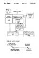
- FIG. 1is an overall block diagram of a preferred embodiment of the present invention.
- FIG. 2is a diagram showing the length of the relevant portions of the operating cycle.
- FIG. 3is a block diagram showing how the components are connected during the "adjustment" portion of the cycle.
- FIG. 4is a block diagram showing how the components are connected during the "receive" portion of the cycle.
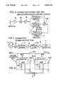
- FIG. 5is a circuit diagram of a two pole on-chip adjustable IF band pass filter.
- FIG. 6is a detailed block diagram of a receiver wherein the present invention is applicable.
- FIG. 1An overall block diagram of a preferred embodiment of the present invention is shown in FIG. 1.
- the major componentsare an integrated circuit chip 110, an external IF filter 111, a filter coefficient adjustment circuit 112, an operating cycle timer 113, and configuration changing gates 113A.
- the integrated circuit chip 110includes thereon a radio receiver 110A, an on-chip filter 110C and a signal comparator 110B.
- the blocks shown in FIG. 1are not meant to show the actual layout of the components on the chip 110 since the layout of the chip can be conventional and it forms no part of this invention.
- the details of the radio receiver 110A and its associated external componentsare shown in FIG. 6 and they will be explained in detail later.
- an FM radio receiverincludes IF filters.
- the parts of the radio receiver on integrated chip 110that is, the radio receiver minus the IF filter, is called a radio receiver.
- a key aspect of the present inventionis that it reduces the number of external or off-chip components required.
- the inventionis applicable to a receiver system that includes two IF filters. With the present invention one of these filters, namely filter 110A, is implemented on-chip and the second filter 111 is an off-chip component.
- the on-chip filteris made to conform to the off-chip filter prior to the activation of the receiver. While the on-chip filter may drift out of the acceptable range of specifications in a relatively short time, the receiver is only activated for a short period and during this period the on-chip filter 110A operates appropriately.
- the radio receiver 110Ais designed for operation in a time slot paging system such as that shown in U.S. Pat. No. 4,713,808 (Gaskill) wherein the receiver is only active for very short periods, each active period being followed by a relative long period of inactivity. Since the receiver is only active for very short periods, it uses relatively little power. This is important in applications such as where the radio receiver is part of a wristwatch where there are very severe power limitations.
- the on-chip filter 110Cis adjusted.
- the receiver 110Ais turned ON for a short period.
- the receiver 110Ais OFF for a long period.
- FIG. 2shows the relative length of the three portions of the operating cycle. Key to the present invention is the fact that the first and second portions of the operating cycle are relatively short with respect to the third portion of the operating cycle. The length of the various portions of the operating cycle is shown in FIG. 2.
- FIG. 3shows how the components in the system are connected during the first portion of each operating cycle.
- FIG. 4shows how the components are connected during the second portion of each operating cycle.
- the circuitis connected so that the on-chip filter 110C can be adjusted.
- the frequency characteristics of on chip filter 110Care made to match the frequency characteristics of external filter 111. This portion of the cycle requires approximately 4.3 milliseconds.
- the on-chip filter 110C and the off-chip filter 111are connected in series as shown in FIG. 4 and the receiver is activated for approximately 33 milliseconds. As explained in the above referenced Gaskill patent, while the receiver is only active for a short period of time, this is time enough to span one time slot in a time slot protocol. In the third, and relatively long portion of each operating cycle, the receiver is deactivated.
- FIG. 5shows the details of the on-chip filter 110C.
- On-chip filter 110Cis a two pole filter which includes two coupled resonators 550A and 550B. The two resonators 550A and 550B are connected by a series coupling capacitor 550C.
- Resonator 550Aincludes on-chip capacitors 501A and 502A, gyrator 503A, and variable resistor 504A.
- Resonator 550Bincludes on-chip capacitors 501B and 502B, gyrator 503B and variable resistor 504B.
- the on-chip components shown in FIG. 5are connected in a conventional fashion to form a band pass filter. Such filters are well know; however, it is also well known that such on-chip gyrators working at 10.7 mHz are relatively unstable. That is, once they are adjusted to certain parameters, they will retain those values for only a short period of time.
- the present inventiontakes advantage of the fact that the receiver 110A is only active for a very short period, that is, for 33 milliseconds. Thus, the parameters are adjusted during the first portion of each cycle and they only need retain their value for the 33 milliseconds that the receiver is active during the second portion of each cycle. Unique to the invention is the fact that the parameters are automatically adjusted each time that the receiver 110 is activated.
- the particular adaptive algorithm used to adjust the parameters or gyrators 503A and 503Bis not relevant to the present invention and such adjustment algorithms are known in the art.
- the details of how receiver 110 is connected into the system during the second or "receive" portion of each cycleare shown in FIG. 6.
- the system as shown in FIG. 6includes an RF stage 10, an IF stage 12 and a baseband stage 14.
- the RF stage 10includes an antenna 116 which may be fabricated into the wristband 17 of the wristwatch 19 in which the receiver 8 is mounted. (A suitable wristwatch enclosure is described in the Gaskill et al patent).
- the antenna 116provides RF signals to an antenna tuner stage 18.
- Antenna tuner stage 18is a conventional varactor controlled bandpass filter which also performs limited impedance match functions.
- a tuning voltageis applied to a tune voltage port 20 from a microprocessor based control system not shown earlier. Such a microprocessor system is discussed in Gaskill et al.
- the voltage supplied via port 20tunes a voltage-variable capacitor in tuner 18.
- the antenna tuner 18also serves a limited impedance transformation function.
- the antenna 116is typically a very small loop and consequently has a very small impedance. Receiver performance and noise figure are optimized if this impedance is transformed up to more closely match the input impedance of the following RF amplifier stage 22.
- RF amplifier stage 22is a low noise broadband amplifier tuned for maximum gain in the FM broadcast band (88-108 megahertz).
- the maximum gain of RF amplifier stage 22is approximately 10 dB.
- the actual gainis controlled by an AGC control circuit discussed below.
- a receiver mixer stage 26is provided with a wide band of amplified input signals.
- mixer stage 26is configured in an image canceling topology.
- Two individual quad mixers 28 and 30are driven with quadrature local oscillator signals on lines 27 and 29 from a local oscillator synthesizer 31. High side injection is used, so the local oscillator tunes the 98.7 to 118.7 megahertz range to yield a 10.7 megahertz intermediate frequency.
- the output of the mixer 28 driven from local oscillator line 27is delayed 90 degrees and is combined with the output of the mixer 30 that is driven from the delayed local oscillator line 29. The combination of these signals cancels any image response while reinforcing the desired signal response.
- Mixer 26has a conversion gain at the desired signal frequency of approximately 7 dB.
- the output of mixer stage 26is provided to an IF chain 32 comprised of two IF amplifiers 34 and 36 and ceramic band pass filters 111 and adaptive filter 110A.
- the filter 110is of chip construction and may be of the SFEC 10.7 series manufactured by Murata. In accordance with the present invention only filter 40 is implemented using an IC chip.
- IF amplifiers 34 and 36have gains of approximately 20 dB each and filters 38 and 49 have about 6 dB each of loss.
- the IF amplifiers 34 and 35can be gain controlled, to optimize noise figure.
- the output of IF chain 32is provided to a synchronous, or coherent detector comprised of a mixer 49 injected with a 10.7 megahertz local oscillator signal.
- the synchronous detection processadds the side band signal voltage and the side band noise powers, resulting in a 3 dB improvement in signal-to noise ratio.
- the techniquealso permits detection at a much lower signal level than would be possible if a limiter stage was employed. Consequently, the IF stage gain can be lower than would normally be the case, thereby reducing the risk of feedback.
- the local oscillator 48which provides the 10.7 megahertz signal is locked to the frequency of the IF by a feedback circuit 71, discussed below.
- a 90 degree phase shift of the local oscillator signal by a phase shifter 47causes the signal output by mixer 49 to an output line 51 to be proportional to the frequency of the signal modulating the 10.7 megahertz IF.
- This baseband frequency modulated signalis fed to a low pass filter 52 and then to a baseband amplifier 53.
- Baseband amplifier 53has a break point of about five kilohertz for discrimination against the left plus right FM stereo channel. The breakpoint also minimizes distortion caused by the main audio channel bleeding into the subcarrier channel.
- the high end rolloff breakpointis at about 150 kilohertz.
- the output of the baseband amplifier 53is provided to conventional decoder circuitry, as disclosed in the Gaskill et al. patent.
- a second synchronous detectoris also driven by the IF chain 32 and provides an AGC signal for application to the RF and IF gain stages.
- This second synchronous detectoragain includes a mixer 60, this one driven in phase with the 10.7 megahertz local oscillator signal. The output of this mixer 60 is thus related to the amplitude of the IF signal and can be used to gain control preceding stages.
- AGC circuitry 24 employed in the preferred embodiment of the present inventionis disclosed in pending U.S. patent application Ser. No. 07/146,446 of Suter entitled “AGC Delay on an Integrated Circuit,” the disclosure of which is incorporated herein by reference.
- An AGC loop filter 70is a single RC stage with a break point at about one kilohertz. All other bypassing of AGC points is done with much higher break points so that the one pole is clearly dominant.
- Radio receiver as shown hereinis AFC controlled in a relatively continual manner.
- AFCis effected by a DC component on the feedback loop 71 produced by a synchronous detector 49.
- An amplifier 74is included to insure that the loop gain is high enough to control local oscillator drift.
- the AFC loopcontrols two local oscillators: The synthesized local oscillator 31 used for high side RF injection and the 10.7 megahertz local oscillator 48 used by the synchronous detectors 49 and 60. Both oscillators respond to any DC component on the feedback loop 71 to adjust their frequencies to minimize the resulting DC output from synchronous detector 49.
- the AFC featureis included here not for threshold extension (which is not viable with a low modulation index), but to reduce cross-modulation of entertainment energy into the receiver's subspectrum due to distortion in the filters 111 and 110B.
- AFC of the synthesizer 31can be disabled by a switch 72, which can be operated to apply a fixed reference voltage to the synthesizer 31 instead of the AFC signal.
Landscapes
- Engineering & Computer Science (AREA)
- Computer Networks & Wireless Communication (AREA)
- Signal Processing (AREA)
- Superheterodyne Receivers (AREA)
- Circuits Of Receivers In General (AREA)
- Networks Using Active Elements (AREA)
Abstract
Description
Claims (8)
Priority Applications (3)
| Application Number | Priority Date | Filing Date | Title |
|---|---|---|---|
| US07/378,724US5031233A (en) | 1989-07-11 | 1989-07-11 | Single chip radio receiver with one off-chip filter |
| AU61433/90AAU6143390A (en) | 1989-07-11 | 1990-07-10 | Single chip radio receiver with one off-chip filter |
| PCT/US1990/003877WO1991001599A1 (en) | 1989-07-11 | 1990-07-10 | Single chip radio receiver with one off-chip filter |
Applications Claiming Priority (1)
| Application Number | Priority Date | Filing Date | Title |
|---|---|---|---|
| US07/378,724US5031233A (en) | 1989-07-11 | 1989-07-11 | Single chip radio receiver with one off-chip filter |
Publications (1)
| Publication Number | Publication Date |
|---|---|
| US5031233Atrue US5031233A (en) | 1991-07-09 |
Family
ID=23494305
Family Applications (1)
| Application Number | Title | Priority Date | Filing Date |
|---|---|---|---|
| US07/378,724Expired - LifetimeUS5031233A (en) | 1989-07-11 | 1989-07-11 | Single chip radio receiver with one off-chip filter |
Country Status (3)
| Country | Link |
|---|---|
| US (1) | US5031233A (en) |
| AU (1) | AU6143390A (en) |
| WO (1) | WO1991001599A1 (en) |
Cited By (54)
| Publication number | Priority date | Publication date | Assignee | Title |
|---|---|---|---|---|
| WO1993001662A1 (en)* | 1991-07-11 | 1993-01-21 | Shimon Neustein | Pager apparatus |
| WO1993007598A1 (en)* | 1991-09-30 | 1993-04-15 | Motorola, Inc. | Combination liquid crystal display driver and varactor voltage power supply |
| US5864750A (en)* | 1993-12-21 | 1999-01-26 | Thomson Consumer Electronics, Inc. | Microcomputer-based carrier detection system for a cordless telephone by comparing an output signal which contains signals no higher in frequency with a frequency threshold value |
| US5881365A (en)* | 1996-01-18 | 1999-03-09 | Clariti Telecommunications International, Ltd. | Digital compressed voice paging system which uses R.D.S. format for the ID signals and S.C.A. format for the voice signals both formats being FM subcarriers |
| US5926753A (en)* | 1996-06-27 | 1999-07-20 | Nec Corporation | Radio selection call receiver capable of increasing receiving ratio |
| US5930686A (en)* | 1993-05-05 | 1999-07-27 | Marconi Electronic Systems Limited | Integrated transceiver circuit packaged component |
| US6043724A (en)* | 1997-12-04 | 2000-03-28 | International Business Machines Corporation | Two-stage power noise filter with on and off chip capacitors |
| US20010007151A1 (en)* | 1998-11-12 | 2001-07-05 | Pieter Vorenkamp | Fully integrated tuner architecture |
| US6426680B1 (en) | 1999-05-26 | 2002-07-30 | Broadcom Corporation | System and method for narrow band PLL tuning |
| US6445039B1 (en) | 1998-11-12 | 2002-09-03 | Broadcom Corporation | System and method for ESD Protection |
| US20020197972A1 (en)* | 2001-06-20 | 2002-12-26 | Motorola, Inc. | Image rejection mixer with switchable high or low side injection |
| US6525609B1 (en) | 1998-11-12 | 2003-02-25 | Broadcom Corporation | Large gain range, high linearity, low noise MOS VGA |
| US20030197810A1 (en)* | 2000-12-15 | 2003-10-23 | Broadcom Corporation | Digital IF demodulator with carrier recovery |
| US6640093B1 (en)* | 1909-06-29 | 2003-10-28 | Sony International (Europe) Gmbh | Broadcast receiver |
| US6696898B1 (en) | 1998-11-12 | 2004-02-24 | Broadcom Corporation | Differential crystal oscillator |
| US20040153879A1 (en)* | 2002-01-22 | 2004-08-05 | Junichi Fukutani | High-frequency signal reception apparatus and manufacturing method thereof |
| US20050008095A1 (en)* | 2004-07-23 | 2005-01-13 | Rush Frederick A. | Apparatus using interrupts for controlling a processor for radio isolation and associated methods |
| US20050028220A1 (en)* | 2003-03-04 | 2005-02-03 | Broadcom Corporation | Television functionality on a chip |
| US6885275B1 (en) | 1998-11-12 | 2005-04-26 | Broadcom Corporation | Multi-track integrated spiral inductor |
| US20050212604A1 (en)* | 2004-02-10 | 2005-09-29 | Cyr Russell J | Programmable radio transceiver |
| US20050228913A1 (en)* | 2004-03-31 | 2005-10-13 | Silicon Laboratories, Inc. | Communication apparatus implementing time domain isolation with restricted bus access |
| US20050258901A1 (en)* | 1998-11-12 | 2005-11-24 | Broadcom Corporation | System and method for linearizing a CMOS differential pair |
| US20050285449A1 (en)* | 2004-06-29 | 2005-12-29 | Rush Frederick A | Keypad scanning with radio event isolation |
| US20060004938A1 (en)* | 2004-06-30 | 2006-01-05 | Silicon Laboratories, Inc. | Communication apparatus including dual timer units |
| US6985035B1 (en) | 1998-11-12 | 2006-01-10 | Broadcom Corporation | System and method for linearizing a CMOS differential pair |
| US6987966B1 (en)* | 1999-10-21 | 2006-01-17 | Broadcom Corporation | Adaptive radio transceiver with polyphase calibration |
| US20060019686A1 (en)* | 2004-07-23 | 2006-01-26 | Rush Frederick A | Method of controlling a processor for radio isolation using a timer |
| US20060018401A1 (en)* | 2004-07-23 | 2006-01-26 | Rush Frederick A | Apparatus using interrupts for controlling a processor for radio isolation and associated method |
| US20060072685A1 (en)* | 2004-09-30 | 2006-04-06 | Silicon Laboratories Inc. | Wireless communication system with hardware-based frequency burst detection |
| US20060125015A1 (en)* | 2004-12-13 | 2006-06-15 | Broadcom Corporation | ESD protection for high voltage applications |
| US20060141946A1 (en)* | 2004-12-29 | 2006-06-29 | Rush Frederick A | Communication apparatus having a standard serial communication interface compatible with radio isolation |
| US20060142064A1 (en)* | 2004-12-29 | 2006-06-29 | Rush Frederick A | Communication apparatus having a SIM interface compatible with radio isolation |
| US20060152870A1 (en)* | 2005-01-07 | 2006-07-13 | Broadcom Corporation | ESD configuration for low parasitic capacitance I/O |
| US7106388B2 (en) | 1999-12-15 | 2006-09-12 | Broadcom Corporation | Digital IF demodulator for video applications |
| US20060227019A1 (en)* | 2005-03-30 | 2006-10-12 | Somayajula Shyam S | Method and system for sampling a signal |
| US20060229024A1 (en)* | 2005-03-30 | 2006-10-12 | Vishakhadatta G Diwakar | System and method for efficient power supply regulation compatible with radio frequency operation |
| US20070009022A1 (en)* | 2005-06-24 | 2007-01-11 | Shaojie Chen | Signal processing task scheduling in a communication apparatus |
| US20070025471A1 (en)* | 2005-06-24 | 2007-02-01 | Shaojie Chen | Communication apparatus including a buffer circuit having first and second portions for alternately storing results |
| US20070140388A1 (en)* | 2005-12-20 | 2007-06-21 | Silicon Laboratories, Inc. | Method and apparatus for acquiring a frequency burst in a radio communication device |
| US20070293163A1 (en)* | 2006-06-15 | 2007-12-20 | John Kilpatrick | Programmable transmitter architecture for non-constant and constant envelope modulation |
| US20070290910A1 (en)* | 2005-06-29 | 2007-12-20 | Shaojie Chen | Wireless communication system including an audio underflow protection mechanism operative with time domain isolation |
| US20080007365A1 (en)* | 2006-06-15 | 2008-01-10 | Jeff Venuti | Continuous gain compensation and fast band selection in a multi-standard, multi-frequency synthesizer |
| US7324496B1 (en) | 2002-05-01 | 2008-01-29 | Nxp B.V. | Highly integrated radio-frequency apparatus and associated methods |
| US20080036536A1 (en)* | 1999-05-26 | 2008-02-14 | Broadcom Corporation | System and method for linearizing a CMOS differential pair |
| US7352411B2 (en) | 2000-12-15 | 2008-04-01 | Broadcom Corporation | Digital IF demodulator |
| US20080174925A1 (en)* | 1999-01-15 | 2008-07-24 | Broadcom Corporation | System and method for ESD protection |
| US7433393B2 (en) | 2004-07-23 | 2008-10-07 | Nxp B.V. | Apparatus for controlling a digital signal processor for radio isolation and associated methods |
| US7508898B2 (en) | 2004-02-10 | 2009-03-24 | Bitwave Semiconductor, Inc. | Programmable radio transceiver |
| US7567637B2 (en) | 2004-09-30 | 2009-07-28 | St-Ericsson Sa | Wireless communication system and method with frequency burst acquisition feature using autocorrelation and narrowband interference detection |
| US20100102877A1 (en)* | 2000-10-11 | 2010-04-29 | Silicon Laboratories Inc. | Method and apparatus for reducing interference |
| US20100172060A1 (en)* | 1999-01-15 | 2010-07-08 | Broadcom Corporation | System and Method for ESD Protection |
| US20100238849A1 (en)* | 2009-03-17 | 2010-09-23 | Provigent Ltd | Transmitter with replaceable power amplifier |
| US8405152B2 (en) | 1999-01-15 | 2013-03-26 | Broadcom Corporation | System and method for ESD protection |
| US10855320B2 (en) | 2018-09-27 | 2020-12-01 | Qualcomm Incorporated | Antenna aperture tuning |
Citations (5)
| Publication number | Priority date | Publication date | Assignee | Title |
|---|---|---|---|---|
| US4177430A (en)* | 1978-03-06 | 1979-12-04 | Rockwell International Corporation | Adaptive noise cancelling receiver |
| US4528698A (en)* | 1983-12-22 | 1985-07-09 | Motorola, Inc. | Tuning system for RF receiver |
| US4761829A (en)* | 1985-11-27 | 1988-08-02 | Motorola Inc. | Adaptive signal strength and/or ambient noise driven audio shaping system |
| US4885802A (en)* | 1988-06-30 | 1989-12-05 | At&E Corporation | Wristwatch receiver architecture |
| US4885801A (en)* | 1986-02-24 | 1989-12-05 | H.U.C. Elektronik Hansen & Co. | Method and circuit for converting frequency-modulated signals through at least one intermediate frequency into low frequency signals |
Family Cites Families (2)
| Publication number | Priority date | Publication date | Assignee | Title |
|---|---|---|---|---|
| US4326294A (en)* | 1979-02-13 | 1982-04-20 | Nippon Telegraph & Telephone Public Corporation | Space diversity reception system having compensation means of multipath effect |
| US4484354A (en)* | 1980-10-16 | 1984-11-20 | Motorola, Inc. | Continuous tone decoder/encoder |
- 1989
- 1989-07-11USUS07/378,724patent/US5031233A/ennot_activeExpired - Lifetime
- 1990
- 1990-07-10WOPCT/US1990/003877patent/WO1991001599A1/enunknown
- 1990-07-10AUAU61433/90Apatent/AU6143390A/ennot_activeAbandoned
Patent Citations (5)
| Publication number | Priority date | Publication date | Assignee | Title |
|---|---|---|---|---|
| US4177430A (en)* | 1978-03-06 | 1979-12-04 | Rockwell International Corporation | Adaptive noise cancelling receiver |
| US4528698A (en)* | 1983-12-22 | 1985-07-09 | Motorola, Inc. | Tuning system for RF receiver |
| US4761829A (en)* | 1985-11-27 | 1988-08-02 | Motorola Inc. | Adaptive signal strength and/or ambient noise driven audio shaping system |
| US4885801A (en)* | 1986-02-24 | 1989-12-05 | H.U.C. Elektronik Hansen & Co. | Method and circuit for converting frequency-modulated signals through at least one intermediate frequency into low frequency signals |
| US4885802A (en)* | 1988-06-30 | 1989-12-05 | At&E Corporation | Wristwatch receiver architecture |
Non-Patent Citations (4)
| Title |
|---|
| "A Complete Single Chip AM/FM Radio IC" Okanobu et al 6/82. |
| A Complete Single Chip AM/FM Radio IC Okanobu et al 6/82.* |
| Continuous Time Adaptive Recursive Filters, Johns et al, pp. 667 670, 1989 IEEE.* |
| Continuous-Time Adaptive Recursive Filters, Johns et al, pp. 667-670, 1989 IEEE. |
Cited By (147)
| Publication number | Priority date | Publication date | Assignee | Title |
|---|---|---|---|---|
| US6640093B1 (en)* | 1909-06-29 | 2003-10-28 | Sony International (Europe) Gmbh | Broadcast receiver |
| WO1993001662A1 (en)* | 1991-07-11 | 1993-01-21 | Shimon Neustein | Pager apparatus |
| WO1993007598A1 (en)* | 1991-09-30 | 1993-04-15 | Motorola, Inc. | Combination liquid crystal display driver and varactor voltage power supply |
| US5930686A (en)* | 1993-05-05 | 1999-07-27 | Marconi Electronic Systems Limited | Integrated transceiver circuit packaged component |
| US5864750A (en)* | 1993-12-21 | 1999-01-26 | Thomson Consumer Electronics, Inc. | Microcomputer-based carrier detection system for a cordless telephone by comparing an output signal which contains signals no higher in frequency with a frequency threshold value |
| US5881365A (en)* | 1996-01-18 | 1999-03-09 | Clariti Telecommunications International, Ltd. | Digital compressed voice paging system which uses R.D.S. format for the ID signals and S.C.A. format for the voice signals both formats being FM subcarriers |
| CN1115060C (en)* | 1996-06-27 | 2003-07-16 | 日本电气株式会社 | Radio selection call receiver capable of increasing receiving ratio |
| US5926753A (en)* | 1996-06-27 | 1999-07-20 | Nec Corporation | Radio selection call receiver capable of increasing receiving ratio |
| US6043724A (en)* | 1997-12-04 | 2000-03-28 | International Business Machines Corporation | Two-stage power noise filter with on and off chip capacitors |
| US20050153677A1 (en)* | 1998-11-12 | 2005-07-14 | Broadcom Corporation | System and method for on-chip filter tuning |
| US7821581B2 (en) | 1998-11-12 | 2010-10-26 | Broadcom Corporation | Fully integrated tuner architecture |
| US20010007151A1 (en)* | 1998-11-12 | 2001-07-05 | Pieter Vorenkamp | Fully integrated tuner architecture |
| US6445039B1 (en) | 1998-11-12 | 2002-09-03 | Broadcom Corporation | System and method for ESD Protection |
| US7236212B2 (en) | 1998-11-12 | 2007-06-26 | Broadcom Corporation | System and method for providing a low power receiver design |
| US6504420B1 (en) | 1998-11-12 | 2003-01-07 | Broadcom Corporation | Temperature compensation for internal inductor resistance |
| US6525609B1 (en) | 1998-11-12 | 2003-02-25 | Broadcom Corporation | Large gain range, high linearity, low noise MOS VGA |
| US6549766B2 (en) | 1998-11-12 | 2003-04-15 | Broadcom Corporation | System and method for on-chip filter tuning |
| US20030107427A1 (en)* | 1998-11-12 | 2003-06-12 | Broadcom Corporation | Temperature compensation for internal inductor resistance |
| US6591091B1 (en) | 1998-11-12 | 2003-07-08 | Broadcom Corporation | System and method for coarse/fine PLL adjustment |
| US6285865B1 (en) | 1998-11-12 | 2001-09-04 | Broadcom Corporation | System and method for on-chip filter tuning |
| US20030194978A1 (en)* | 1998-11-12 | 2003-10-16 | Pieter Vorenkamp | System and method for coarse/fine PLL adjustment |
| US8227892B2 (en) | 1998-11-12 | 2012-07-24 | Broadcom Corporation | Multi-track integrated circuit inductor |
| WO2000028664A3 (en)* | 1998-11-12 | 2001-07-26 | Broadcom Corp | Fully integrated tuner architecture |
| US6696898B1 (en) | 1998-11-12 | 2004-02-24 | Broadcom Corporation | Differential crystal oscillator |
| US6759904B2 (en) | 1998-11-12 | 2004-07-06 | Broadcom Corporation | Large gain range, high linearity, low noise MOS VGA |
| US8195117B2 (en) | 1998-11-12 | 2012-06-05 | Broadcom Corporation | Integrated switchless programmable attenuator and low noise amplifier |
| US20040160286A1 (en)* | 1998-11-12 | 2004-08-19 | Broadcom Corporation | Applications for differential cystal oscillator |
| US7199664B2 (en) | 1998-11-12 | 2007-04-03 | Broadcom Corporation | Integrated switchless programmable attenuator and low noise amplifier |
| US20040212417A1 (en)* | 1998-11-12 | 2004-10-28 | Behzad Arya R. | Large gain range, high linearity, low noise MOS VGA |
| US8111095B2 (en) | 1998-11-12 | 2012-02-07 | Broadcom Corporation | Temperature compensation for internal inductor resistance |
| US8045066B2 (en) | 1998-11-12 | 2011-10-25 | Broadcom Corporation | Fully integrated tuner architecture |
| US20050030108A1 (en)* | 1998-11-12 | 2005-02-10 | Broadcom Corporation | Integrated VCO having an improved tuning range over process and temperature variations |
| US6865381B2 (en) | 1998-11-12 | 2005-03-08 | Broadcom Corporation | System and method for on-chip filter tuning |
| US6879816B2 (en) | 1998-11-12 | 2005-04-12 | Broadcom Corporation | Integrated switchless programmable attenuator and low noise amplifier |
| US6885275B1 (en) | 1998-11-12 | 2005-04-26 | Broadcom Corporation | Multi-track integrated spiral inductor |
| US20050107055A1 (en)* | 1998-11-12 | 2005-05-19 | Broadcom Corporation | Integrated switchless programmable attenuator and low noise amplifier |
| US20070120605A1 (en)* | 1998-11-12 | 2007-05-31 | Broadcom Corporation | Integrated switchless programmable attenuator and low noise amplifier |
| US20050156700A1 (en)* | 1998-11-12 | 2005-07-21 | Broadcom Corporation | Integrated spiral inductor |
| US7276970B2 (en) | 1998-11-12 | 2007-10-02 | Broadcom Corporation | System and method for linearizing a CMOS differential pair |
| US20110067083A1 (en)* | 1998-11-12 | 2011-03-17 | Broadcom Corporation | Fully Integrated Tuner Architecture |
| US6377315B1 (en) | 1998-11-12 | 2002-04-23 | Broadcom Corporation | System and method for providing a low power receiver design |
| US20100245012A1 (en)* | 1998-11-12 | 2010-09-30 | Broadcom Corporation | Integrated Spiral Inductor |
| US20050236673A1 (en)* | 1998-11-12 | 2005-10-27 | Broadcom Corporation | System and method for ESD protection |
| US6963248B2 (en) | 1998-11-12 | 2005-11-08 | Broadcom Corporation | Phase locked loop |
| US6963110B2 (en) | 1998-11-12 | 2005-11-08 | Broadcom Corporation | System and method for ESD protection |
| US20050258901A1 (en)* | 1998-11-12 | 2005-11-24 | Broadcom Corporation | System and method for linearizing a CMOS differential pair |
| US20100237884A1 (en)* | 1998-11-12 | 2010-09-23 | Broadcom Corporation | Integrated switchless programmable attenuator and low noise amplifier |
| US20070013433A1 (en)* | 1998-11-12 | 2007-01-18 | Broadcom Corporation | Temperature compensation for internal inductor resistance |
| US6985035B1 (en) | 1998-11-12 | 2006-01-10 | Broadcom Corporation | System and method for linearizing a CMOS differential pair |
| US20070007598A1 (en)* | 1998-11-12 | 2007-01-11 | Broadcom Corporation | System and method for ESD protection |
| US7729676B2 (en) | 1998-11-12 | 2010-06-01 | Broadcom Corporation | Integrated switchless programmable attenuator and low noise amplifier |
| US7719083B2 (en) | 1998-11-12 | 2010-05-18 | Broadcomm Corporation | Integrated spiral inductor |
| US7019598B2 (en) | 1998-11-12 | 2006-03-28 | Broadcom Corporation | Integrated VCO having an improved tuning range over process and temperature variations |
| US7132888B2 (en) | 1998-11-12 | 2006-11-07 | Broadcom—Corporation | Large gain range, high linearity, low noise MOS VGA |
| US7692247B2 (en) | 1998-11-12 | 2010-04-06 | Broadcom Corporation | System and method for ESD protection |
| US7366486B2 (en) | 1998-11-12 | 2008-04-29 | Broadcom Corporation | System and method for coarse/fine PLL adjustment |
| US7515895B2 (en) | 1998-11-12 | 2009-04-07 | Broadcom Corporation | System and method for on-chip filter tuning |
| US7423699B2 (en) | 1998-11-12 | 2008-09-09 | Broadcom Corporation | Fully integrated tuner architecture |
| US7092043B2 (en) | 1998-11-12 | 2006-08-15 | Broadcom Corporation | Fully integrated tuner architecture |
| US7417303B2 (en) | 1998-11-12 | 2008-08-26 | Broadcom Corporation | System and method for ESD protection |
| US7109781B2 (en) | 1998-11-12 | 2006-09-19 | Broadcom Corporation | Temperature compensation for internal inductor resistance |
| US7115952B2 (en) | 1998-11-12 | 2006-10-03 | Broadcom Corporation | System and method for ESD protection |
| US20080174925A1 (en)* | 1999-01-15 | 2008-07-24 | Broadcom Corporation | System and method for ESD protection |
| US7687858B2 (en) | 1999-01-15 | 2010-03-30 | Broadcom Corporation | System and method for ESD protection |
| US20100172060A1 (en)* | 1999-01-15 | 2010-07-08 | Broadcom Corporation | System and Method for ESD Protection |
| US8035162B2 (en) | 1999-01-15 | 2011-10-11 | Broadcom Corporation | System and method for ESD protection |
| US8405152B2 (en) | 1999-01-15 | 2013-03-26 | Broadcom Corporation | System and method for ESD protection |
| US7696823B2 (en) | 1999-05-26 | 2010-04-13 | Broadcom Corporation | System and method for linearizing a CMOS differential pair |
| US20080036536A1 (en)* | 1999-05-26 | 2008-02-14 | Broadcom Corporation | System and method for linearizing a CMOS differential pair |
| US6803829B2 (en) | 1999-05-26 | 2004-10-12 | Broadcom Corporation | Integrated VCO having an improved tuning range over process and temperature variations |
| US6426680B1 (en) | 1999-05-26 | 2002-07-30 | Broadcom Corporation | System and method for narrow band PLL tuning |
| US6987966B1 (en)* | 1999-10-21 | 2006-01-17 | Broadcom Corporation | Adaptive radio transceiver with polyphase calibration |
| US20070105504A1 (en)* | 1999-12-15 | 2007-05-10 | Broadcom Corporation | Digital IF demodulator for video applications |
| US7106388B2 (en) | 1999-12-15 | 2006-09-12 | Broadcom Corporation | Digital IF demodulator for video applications |
| US8711288B2 (en) | 1999-12-15 | 2014-04-29 | Broadcom Corporation | Digital IF demodulator for video applications |
| US7884666B1 (en)* | 2000-10-11 | 2011-02-08 | Silicon Laboratories Inc. | Method and apparatus for reducing interference |
| US8648653B2 (en) | 2000-10-11 | 2014-02-11 | Silicon Laboratories Inc. | Method and apparatus for reducing interference |
| US20100102877A1 (en)* | 2000-10-11 | 2010-04-29 | Silicon Laboratories Inc. | Method and apparatus for reducing interference |
| US20030197810A1 (en)* | 2000-12-15 | 2003-10-23 | Broadcom Corporation | Digital IF demodulator with carrier recovery |
| US7834937B2 (en) | 2000-12-15 | 2010-11-16 | Broadcom Corporation | Digital IF demodulator |
| US7239357B2 (en) | 2000-12-15 | 2007-07-03 | Broadcom Corporation | Digital IF demodulator with carrier recovery |
| US20080180578A1 (en)* | 2000-12-15 | 2008-07-31 | Broadcom Corporation | Digital IF modulator |
| US7352411B2 (en) | 2000-12-15 | 2008-04-01 | Broadcom Corporation | Digital IF demodulator |
| US20020197972A1 (en)* | 2001-06-20 | 2002-12-26 | Motorola, Inc. | Image rejection mixer with switchable high or low side injection |
| US6952572B2 (en) | 2001-06-20 | 2005-10-04 | Freescale Semiconductor, Inc. | Image rejection mixer with switchable high or low side injection |
| US7630686B2 (en)* | 2002-01-22 | 2009-12-08 | Panasonic Corporation | Radio-frequency-signal receiver and method of manufacturing the same |
| US20040153879A1 (en)* | 2002-01-22 | 2004-08-05 | Junichi Fukutani | High-frequency signal reception apparatus and manufacturing method thereof |
| US7324496B1 (en) | 2002-05-01 | 2008-01-29 | Nxp B.V. | Highly integrated radio-frequency apparatus and associated methods |
| US20050028220A1 (en)* | 2003-03-04 | 2005-02-03 | Broadcom Corporation | Television functionality on a chip |
| US7961255B2 (en) | 2003-03-04 | 2011-06-14 | Broadcom Corporation | Television functionality on a chip |
| US7489362B2 (en) | 2003-03-04 | 2009-02-10 | Broadcom Corporation | Television functionality on a chip |
| US8854545B2 (en) | 2003-03-04 | 2014-10-07 | Broadcom Corporation | Television functionality on a chip |
| US20050227627A1 (en)* | 2004-02-10 | 2005-10-13 | Cyr Russell J | Programmable radio transceiver |
| US20090079524A1 (en)* | 2004-02-10 | 2009-03-26 | Bitwave Semiconductor, Inc. | Multi-band tunable resonant circuit |
| US7580684B2 (en) | 2004-02-10 | 2009-08-25 | Bitwave Semiconductor, Inc. | Programmable radio transceiver |
| US20050212604A1 (en)* | 2004-02-10 | 2005-09-29 | Cyr Russell J | Programmable radio transceiver |
| US7482887B2 (en) | 2004-02-10 | 2009-01-27 | Bitwave Semiconductor, Inc. | Multi-band tunable resonant circuit |
| US7323945B2 (en) | 2004-02-10 | 2008-01-29 | Bitwave Semiconductor, Inc. | Programmable radio transceiver |
| US7508898B2 (en) | 2004-02-10 | 2009-03-24 | Bitwave Semiconductor, Inc. | Programmable radio transceiver |
| US8478921B2 (en) | 2004-03-31 | 2013-07-02 | Silicon Laboratories, Inc. | Communication apparatus implementing time domain isolation with restricted bus access |
| US20050228913A1 (en)* | 2004-03-31 | 2005-10-13 | Silicon Laboratories, Inc. | Communication apparatus implementing time domain isolation with restricted bus access |
| US20050285449A1 (en)* | 2004-06-29 | 2005-12-29 | Rush Frederick A | Keypad scanning with radio event isolation |
| US8884791B2 (en) | 2004-06-29 | 2014-11-11 | St-Ericsson Sa | Keypad scanning with radio event isolation |
| US20060004938A1 (en)* | 2004-06-30 | 2006-01-05 | Silicon Laboratories, Inc. | Communication apparatus including dual timer units |
| US7248848B2 (en) | 2004-06-30 | 2007-07-24 | Matthews Phillip M | Communication apparatus including dual timer units |
| US7761056B2 (en) | 2004-07-23 | 2010-07-20 | St-Ericsson Sa | Method of controlling a processor for radio isolation using a timer |
| US20050008095A1 (en)* | 2004-07-23 | 2005-01-13 | Rush Frederick A. | Apparatus using interrupts for controlling a processor for radio isolation and associated methods |
| US20060019686A1 (en)* | 2004-07-23 | 2006-01-26 | Rush Frederick A | Method of controlling a processor for radio isolation using a timer |
| US7433393B2 (en) | 2004-07-23 | 2008-10-07 | Nxp B.V. | Apparatus for controlling a digital signal processor for radio isolation and associated methods |
| US8472990B2 (en) | 2004-07-23 | 2013-06-25 | St Ericsson Sa | Apparatus using interrupts for controlling a processor for radio isolation and associated method |
| US20060018401A1 (en)* | 2004-07-23 | 2006-01-26 | Rush Frederick A | Apparatus using interrupts for controlling a processor for radio isolation and associated method |
| US7593482B2 (en) | 2004-09-30 | 2009-09-22 | St-Ericsson Sa | Wireless communication system with hardware-based frequency burst detection |
| US20060072685A1 (en)* | 2004-09-30 | 2006-04-06 | Silicon Laboratories Inc. | Wireless communication system with hardware-based frequency burst detection |
| US7567637B2 (en) | 2004-09-30 | 2009-07-28 | St-Ericsson Sa | Wireless communication system and method with frequency burst acquisition feature using autocorrelation and narrowband interference detection |
| US20060125015A1 (en)* | 2004-12-13 | 2006-06-15 | Broadcom Corporation | ESD protection for high voltage applications |
| US20090045464A1 (en)* | 2004-12-13 | 2009-02-19 | Broadcom Corporation | ESD protection for high voltage applications |
| US7439592B2 (en) | 2004-12-13 | 2008-10-21 | Broadcom Corporation | ESD protection for high voltage applications |
| US8049278B2 (en) | 2004-12-13 | 2011-11-01 | Broadcom Corporation | ESD protection for high voltage applications |
| US20060141946A1 (en)* | 2004-12-29 | 2006-06-29 | Rush Frederick A | Communication apparatus having a standard serial communication interface compatible with radio isolation |
| US7778674B2 (en) | 2004-12-29 | 2010-08-17 | St-Ericsson Sa | Communication apparatus having a SIM interface compatible with radio isolation |
| US20060142064A1 (en)* | 2004-12-29 | 2006-06-29 | Rush Frederick A | Communication apparatus having a SIM interface compatible with radio isolation |
| US8019382B2 (en) | 2004-12-29 | 2011-09-13 | St-Ericsson Sa | Communication apparatus having a standard serial communication interface compatible with radio isolation |
| US20060152870A1 (en)* | 2005-01-07 | 2006-07-13 | Broadcom Corporation | ESD configuration for low parasitic capacitance I/O |
| US20090161276A1 (en)* | 2005-01-07 | 2009-06-25 | Broadcom Corporation | ESD Configuration for Low Parasitic Capacitance I/O |
| US7920366B2 (en) | 2005-01-07 | 2011-04-05 | Broadcom Corporation | ESD configuration for low parasitic capacitance I/O |
| US7505238B2 (en) | 2005-01-07 | 2009-03-17 | Agnes Neves Woo | ESD configuration for low parasitic capacitance I/O |
| US7209061B2 (en) | 2005-03-30 | 2007-04-24 | Silicon Laboratories, Inc. | Method and system for sampling a signal |
| US7805170B2 (en) | 2005-03-30 | 2010-09-28 | St-Ericsson Sa | System and method for efficient power supply regulation compatible with radio frequency operation |
| US20060229024A1 (en)* | 2005-03-30 | 2006-10-12 | Vishakhadatta G Diwakar | System and method for efficient power supply regulation compatible with radio frequency operation |
| US20060227019A1 (en)* | 2005-03-30 | 2006-10-12 | Somayajula Shyam S | Method and system for sampling a signal |
| US7424275B2 (en) | 2005-03-30 | 2008-09-09 | Silicon Laboratories, Inc. | Method and system for sampling a signal |
| US7289477B2 (en) | 2005-06-24 | 2007-10-30 | Silicon Laboratories, Inc. | Communication apparatus including a buffer circuit having first and second portions for alternately storing results |
| US20070009022A1 (en)* | 2005-06-24 | 2007-01-11 | Shaojie Chen | Signal processing task scheduling in a communication apparatus |
| US7801207B2 (en) | 2005-06-24 | 2010-09-21 | St-Ericsson Sa | Signal processing task scheduling in a communication apparatus |
| US20070025471A1 (en)* | 2005-06-24 | 2007-02-01 | Shaojie Chen | Communication apparatus including a buffer circuit having first and second portions for alternately storing results |
| US7283503B1 (en) | 2005-06-24 | 2007-10-16 | Silicon Laboratories, Inc. | Communication apparatus including a buffer circuit having first and second portions for alternately storing results |
| US20070290910A1 (en)* | 2005-06-29 | 2007-12-20 | Shaojie Chen | Wireless communication system including an audio underflow protection mechanism operative with time domain isolation |
| US7414560B2 (en) | 2005-06-29 | 2008-08-19 | Shaojie Chen | Wireless communication system including an audio underflow protection mechanism operative with time domain isolation |
| US7864891B2 (en) | 2005-12-20 | 2011-01-04 | Silicon Laboratories Inc. | Method and apparatus for acquiring a frequency burst in a radio communication device |
| US20070140388A1 (en)* | 2005-12-20 | 2007-06-21 | Silicon Laboratories, Inc. | Method and apparatus for acquiring a frequency burst in a radio communication device |
| US20080007365A1 (en)* | 2006-06-15 | 2008-01-10 | Jeff Venuti | Continuous gain compensation and fast band selection in a multi-standard, multi-frequency synthesizer |
| US20070293163A1 (en)* | 2006-06-15 | 2007-12-20 | John Kilpatrick | Programmable transmitter architecture for non-constant and constant envelope modulation |
| US7672645B2 (en) | 2006-06-15 | 2010-03-02 | Bitwave Semiconductor, Inc. | Programmable transmitter architecture for non-constant and constant envelope modulation |
| US20100238849A1 (en)* | 2009-03-17 | 2010-09-23 | Provigent Ltd | Transmitter with replaceable power amplifier |
| US8798564B2 (en)* | 2009-03-17 | 2014-08-05 | Provigent Ltd. | Transmitter with replaceable power amplifier |
| US10855320B2 (en) | 2018-09-27 | 2020-12-01 | Qualcomm Incorporated | Antenna aperture tuning |
| US11563456B2 (en) | 2018-09-27 | 2023-01-24 | Qualcomm Incorporated | Antenna aperture tuning |
Also Published As
| Publication number | Publication date |
|---|---|
| AU6143390A (en) | 1991-02-22 |
| WO1991001599A1 (en) | 1991-02-07 |
Similar Documents
| Publication | Publication Date | Title |
|---|---|---|
| US5031233A (en) | Single chip radio receiver with one off-chip filter | |
| US5852784A (en) | Multiband mobile unit communication apparatus | |
| US20040033794A1 (en) | Resonator configuration | |
| US20020003585A1 (en) | Television tuner capable of receiving FM broadcast | |
| US7013124B2 (en) | Wide band tuner | |
| US5262741A (en) | Attenuator for high-frequency signal | |
| US4355413A (en) | Phase locked loop circuit | |
| WO1991002413A1 (en) | Radio receiver frequency control system | |
| JP2000341091A (en) | Input trap circuit and image trap circuit | |
| US6169447B1 (en) | Stabilization of passband active filters | |
| JPH07321603A (en) | Tuner | |
| Kasperkovitz | An integrated FM receiver | |
| JP3838030B2 (en) | High frequency signal receiver | |
| JP3187204B2 (en) | FM modulator | |
| KR960013785B1 (en) | Tunner | |
| KR0132903Y1 (en) | Antenna automatic adjustment circuit | |
| JPS6211539B2 (en) | ||
| JPS6012828A (en) | Frequency synthesizer tuner having automatic adjusting function of radio frequency part | |
| JPH0129875Y2 (en) | ||
| JPH0232816B2 (en) | JUSHINKAIRO | |
| JPS5935534B2 (en) | PLL circuit | |
| KR0177689B1 (en) | Rf type tunner | |
| JP3065761B2 (en) | Filter device | |
| JPH11127395A (en) | Television tuner | |
| JPH0918293A (en) | High frequency input circuit and receiver |
Legal Events
| Date | Code | Title | Description |
|---|---|---|---|
| AS | Assignment | Owner name:AT&E CORPORATION, ONE MARITIME PLAZA, SAN FRANCISC Free format text:ASSIGNMENT OF ASSIGNORS INTEREST.;ASSIGNOR:RAGAN, LAWRENCE H.;REEL/FRAME:005100/0887 Effective date:19890711 | |
| STCF | Information on status: patent grant | Free format text:PATENTED CASE | |
| AS | Assignment | Owner name:SEIKO CORPORATION, JAPAN Free format text:ASSIGNMENT OF ASSIGNORS INTEREST.;ASSIGNOR:AT&E CORPORATION;REEL/FRAME:005996/0617 Effective date:19911231 Owner name:SEIKO EPSON CORPORATION, JAPAN Free format text:ASSIGNMENT OF ASSIGNORS INTEREST.;ASSIGNOR:AT&E CORPORATION;REEL/FRAME:005996/0617 Effective date:19911231 | |
| FEPP | Fee payment procedure | Free format text:PAT HLDR NO LONGER CLAIMS SMALL ENT STAT AS INDIV INVENTOR (ORIGINAL EVENT CODE: LSM1); ENTITY STATUS OF PATENT OWNER: LARGE ENTITY | |
| FPAY | Fee payment | Year of fee payment:4 | |
| FPAY | Fee payment | Year of fee payment:8 | |
| FPAY | Fee payment | Year of fee payment:12 | |
| AS | Assignment | Owner name:SEIKO INSTRUMENTS INC., JAPAN Free format text:ASSIGNMENT OF ASSIGNORS INTEREST;ASSIGNORS:SEIKO CORPORATION;SEIKO EPSON CORPORATION;REEL/FRAME:018398/0844;SIGNING DATES FROM 20060621 TO 20060920 | |
| AS | Assignment | Owner name:SEIKO HOLDINGS CORPORATION, JAPAN Free format text:CHANGE OF NAME;ASSIGNOR:SEIKO CORPORATION;REEL/FRAME:021029/0634 Effective date:20070701 Owner name:SEIKO INSTRUMENTS INC., JAPAN Free format text:ASSIGNMENT OF ASSIGNORS INTEREST;ASSIGNORS:SEIKO HOLDINGS CORPORATION;SEIKO EPSON CORPORATION;REEL/FRAME:021029/0649;SIGNING DATES FROM 20080423 TO 20080505 | |
| FEPP | Fee payment procedure | Free format text:PAYER NUMBER DE-ASSIGNED (ORIGINAL EVENT CODE: RMPN); ENTITY STATUS OF PATENT OWNER: LARGE ENTITY Free format text:PAYOR NUMBER ASSIGNED (ORIGINAL EVENT CODE: ASPN); ENTITY STATUS OF PATENT OWNER: LARGE ENTITY | |
| AS | Assignment | Owner name:PROTOCOL-IP.COM, L.L.C., DELAWARE Free format text:ASSIGNMENT OF ASSIGNORS INTEREST;ASSIGNOR:SEIKO INSTRUMENTS INC.;REEL/FRAME:022024/0063 Effective date:20080201 |