US5030208A - Safety syringe needle device with interchangeable and retractable needle platform - Google Patents
Safety syringe needle device with interchangeable and retractable needle platformDownload PDFInfo
- Publication number
- US5030208A US5030208AUS07/410,318US41031889AUS5030208AUS 5030208 AUS5030208 AUS 5030208AUS 41031889 AUS41031889 AUS 41031889AUS 5030208 AUS5030208 AUS 5030208A
- Authority
- US
- United States
- Prior art keywords
- barrel
- plunger
- adapter
- syringe
- needle
- Prior art date
- Legal status (The legal status is an assumption and is not a legal conclusion. Google has not performed a legal analysis and makes no representation as to the accuracy of the status listed.)
- Expired - Lifetime
Links
Images


Classifications
- A—HUMAN NECESSITIES
- A61—MEDICAL OR VETERINARY SCIENCE; HYGIENE
- A61L—METHODS OR APPARATUS FOR STERILISING MATERIALS OR OBJECTS IN GENERAL; DISINFECTION, STERILISATION OR DEODORISATION OF AIR; CHEMICAL ASPECTS OF BANDAGES, DRESSINGS, ABSORBENT PADS OR SURGICAL ARTICLES; MATERIALS FOR BANDAGES, DRESSINGS, ABSORBENT PADS OR SURGICAL ARTICLES
- A61L2/00—Methods or apparatus for disinfecting or sterilising materials or objects other than foodstuffs or contact lenses; Accessories therefor
- A61L2/26—Accessories or devices or components used for biocidal treatment
- A61L2/28—Devices for testing the effectiveness or completeness of sterilisation, e.g. indicators which change colour
- A—HUMAN NECESSITIES
- A61—MEDICAL OR VETERINARY SCIENCE; HYGIENE
- A61M—DEVICES FOR INTRODUCING MEDIA INTO, OR ONTO, THE BODY; DEVICES FOR TRANSDUCING BODY MEDIA OR FOR TAKING MEDIA FROM THE BODY; DEVICES FOR PRODUCING OR ENDING SLEEP OR STUPOR
- A61M5/00—Devices for bringing media into the body in a subcutaneous, intra-vascular or intramuscular way; Accessories therefor, e.g. filling or cleaning devices, arm-rests
- A61M5/178—Syringes
- A61M5/31—Details
- A61M5/32—Needles; Details of needles pertaining to their connection with syringe or hub; Accessories for bringing the needle into, or holding the needle on, the body; Devices for protection of needles
- A61M5/3202—Devices for protection of the needle before use, e.g. caps
- A—HUMAN NECESSITIES
- A61—MEDICAL OR VETERINARY SCIENCE; HYGIENE
- A61M—DEVICES FOR INTRODUCING MEDIA INTO, OR ONTO, THE BODY; DEVICES FOR TRANSDUCING BODY MEDIA OR FOR TAKING MEDIA FROM THE BODY; DEVICES FOR PRODUCING OR ENDING SLEEP OR STUPOR
- A61M5/00—Devices for bringing media into the body in a subcutaneous, intra-vascular or intramuscular way; Accessories therefor, e.g. filling or cleaning devices, arm-rests
- A61M5/178—Syringes
- A61M5/31—Details
- A61M5/32—Needles; Details of needles pertaining to their connection with syringe or hub; Accessories for bringing the needle into, or holding the needle on, the body; Devices for protection of needles
- A61M5/3205—Apparatus for removing or disposing of used needles or syringes, e.g. containers; Means for protection against accidental injuries from used needles
- A61M5/321—Means for protection against accidental injuries by used needles
- A61M5/322—Retractable needles, i.e. disconnected from and withdrawn into the syringe barrel by the piston
- A—HUMAN NECESSITIES
- A61—MEDICAL OR VETERINARY SCIENCE; HYGIENE
- A61M—DEVICES FOR INTRODUCING MEDIA INTO, OR ONTO, THE BODY; DEVICES FOR TRANSDUCING BODY MEDIA OR FOR TAKING MEDIA FROM THE BODY; DEVICES FOR PRODUCING OR ENDING SLEEP OR STUPOR
- A61M5/00—Devices for bringing media into the body in a subcutaneous, intra-vascular or intramuscular way; Accessories therefor, e.g. filling or cleaning devices, arm-rests
- A61M5/50—Devices for bringing media into the body in a subcutaneous, intra-vascular or intramuscular way; Accessories therefor, e.g. filling or cleaning devices, arm-rests having means for preventing re-use, or for indicating if defective, used, tampered with or unsterile
- A61M5/5086—Devices for bringing media into the body in a subcutaneous, intra-vascular or intramuscular way; Accessories therefor, e.g. filling or cleaning devices, arm-rests having means for preventing re-use, or for indicating if defective, used, tampered with or unsterile for indicating if defective, used, tampered with or unsterile
- A—HUMAN NECESSITIES
- A61—MEDICAL OR VETERINARY SCIENCE; HYGIENE
- A61M—DEVICES FOR INTRODUCING MEDIA INTO, OR ONTO, THE BODY; DEVICES FOR TRANSDUCING BODY MEDIA OR FOR TAKING MEDIA FROM THE BODY; DEVICES FOR PRODUCING OR ENDING SLEEP OR STUPOR
- A61M5/00—Devices for bringing media into the body in a subcutaneous, intra-vascular or intramuscular way; Accessories therefor, e.g. filling or cleaning devices, arm-rests
- A61M5/178—Syringes
- A61M5/31—Details
- A61M2005/3101—Leak prevention means for proximal end of syringes, i.e. syringe end opposite to needle mounting end
- A—HUMAN NECESSITIES
- A61—MEDICAL OR VETERINARY SCIENCE; HYGIENE
- A61M—DEVICES FOR INTRODUCING MEDIA INTO, OR ONTO, THE BODY; DEVICES FOR TRANSDUCING BODY MEDIA OR FOR TAKING MEDIA FROM THE BODY; DEVICES FOR PRODUCING OR ENDING SLEEP OR STUPOR
- A61M5/00—Devices for bringing media into the body in a subcutaneous, intra-vascular or intramuscular way; Accessories therefor, e.g. filling or cleaning devices, arm-rests
- A61M5/178—Syringes
- A61M5/31—Details
- A61M2005/3103—Leak prevention means for distal end of syringes, i.e. syringe end for mounting a needle
- A61M2005/3104—Caps for syringes without needle
- A—HUMAN NECESSITIES
- A61—MEDICAL OR VETERINARY SCIENCE; HYGIENE
- A61M—DEVICES FOR INTRODUCING MEDIA INTO, OR ONTO, THE BODY; DEVICES FOR TRANSDUCING BODY MEDIA OR FOR TAKING MEDIA FROM THE BODY; DEVICES FOR PRODUCING OR ENDING SLEEP OR STUPOR
- A61M5/00—Devices for bringing media into the body in a subcutaneous, intra-vascular or intramuscular way; Accessories therefor, e.g. filling or cleaning devices, arm-rests
- A61M5/178—Syringes
- A61M5/31—Details
- A61M2005/3103—Leak prevention means for distal end of syringes, i.e. syringe end for mounting a needle
- A61M2005/3106—Plugs for syringes without needle
- A—HUMAN NECESSITIES
- A61—MEDICAL OR VETERINARY SCIENCE; HYGIENE
- A61M—DEVICES FOR INTRODUCING MEDIA INTO, OR ONTO, THE BODY; DEVICES FOR TRANSDUCING BODY MEDIA OR FOR TAKING MEDIA FROM THE BODY; DEVICES FOR PRODUCING OR ENDING SLEEP OR STUPOR
- A61M5/00—Devices for bringing media into the body in a subcutaneous, intra-vascular or intramuscular way; Accessories therefor, e.g. filling or cleaning devices, arm-rests
- A61M5/178—Syringes
- A61M5/31—Details
- A61M2005/3117—Means preventing contamination of the medicament compartment of a syringe
- A61M2005/3118—Means preventing contamination of the medicament compartment of a syringe via the distal end of a syringe, i.e. syringe end for mounting a needle cannula
- A—HUMAN NECESSITIES
- A61—MEDICAL OR VETERINARY SCIENCE; HYGIENE
- A61M—DEVICES FOR INTRODUCING MEDIA INTO, OR ONTO, THE BODY; DEVICES FOR TRANSDUCING BODY MEDIA OR FOR TAKING MEDIA FROM THE BODY; DEVICES FOR PRODUCING OR ENDING SLEEP OR STUPOR
- A61M5/00—Devices for bringing media into the body in a subcutaneous, intra-vascular or intramuscular way; Accessories therefor, e.g. filling or cleaning devices, arm-rests
- A61M5/178—Syringes
- A61M5/31—Details
- A61M2005/3117—Means preventing contamination of the medicament compartment of a syringe
- A61M2005/3121—Means preventing contamination of the medicament compartment of a syringe via the proximal end of a syringe, i.e. syringe end opposite to needle cannula mounting end
- A—HUMAN NECESSITIES
- A61—MEDICAL OR VETERINARY SCIENCE; HYGIENE
- A61M—DEVICES FOR INTRODUCING MEDIA INTO, OR ONTO, THE BODY; DEVICES FOR TRANSDUCING BODY MEDIA OR FOR TAKING MEDIA FROM THE BODY; DEVICES FOR PRODUCING OR ENDING SLEEP OR STUPOR
- A61M5/00—Devices for bringing media into the body in a subcutaneous, intra-vascular or intramuscular way; Accessories therefor, e.g. filling or cleaning devices, arm-rests
- A61M5/178—Syringes
- A61M5/31—Details
- A61M5/32—Needles; Details of needles pertaining to their connection with syringe or hub; Accessories for bringing the needle into, or holding the needle on, the body; Devices for protection of needles
- A61M5/3205—Apparatus for removing or disposing of used needles or syringes, e.g. containers; Means for protection against accidental injuries from used needles
- A61M5/321—Means for protection against accidental injuries by used needles
- A61M5/322—Retractable needles, i.e. disconnected from and withdrawn into the syringe barrel by the piston
- A61M5/3221—Constructional features thereof, e.g. to improve manipulation or functioning
- A61M2005/3223—Means impeding or disabling repositioning of used needles at the syringe nozzle
- A61M2005/3224—Means to disalign the needle tip and syringe nozzle
- A—HUMAN NECESSITIES
- A61—MEDICAL OR VETERINARY SCIENCE; HYGIENE
- A61M—DEVICES FOR INTRODUCING MEDIA INTO, OR ONTO, THE BODY; DEVICES FOR TRANSDUCING BODY MEDIA OR FOR TAKING MEDIA FROM THE BODY; DEVICES FOR PRODUCING OR ENDING SLEEP OR STUPOR
- A61M5/00—Devices for bringing media into the body in a subcutaneous, intra-vascular or intramuscular way; Accessories therefor, e.g. filling or cleaning devices, arm-rests
- A61M5/178—Syringes
- A61M5/31—Details
- A61M5/32—Needles; Details of needles pertaining to their connection with syringe or hub; Accessories for bringing the needle into, or holding the needle on, the body; Devices for protection of needles
- A61M5/3205—Apparatus for removing or disposing of used needles or syringes, e.g. containers; Means for protection against accidental injuries from used needles
- A61M5/321—Means for protection against accidental injuries by used needles
- A61M5/322—Retractable needles, i.e. disconnected from and withdrawn into the syringe barrel by the piston
- A61M5/3221—Constructional features thereof, e.g. to improve manipulation or functioning
- A61M2005/3231—Proximal end of needle captured or embedded inside piston head, e.g. by friction or hooks
- A—HUMAN NECESSITIES
- A61—MEDICAL OR VETERINARY SCIENCE; HYGIENE
- A61M—DEVICES FOR INTRODUCING MEDIA INTO, OR ONTO, THE BODY; DEVICES FOR TRANSDUCING BODY MEDIA OR FOR TAKING MEDIA FROM THE BODY; DEVICES FOR PRODUCING OR ENDING SLEEP OR STUPOR
- A61M5/00—Devices for bringing media into the body in a subcutaneous, intra-vascular or intramuscular way; Accessories therefor, e.g. filling or cleaning devices, arm-rests
- A61M5/178—Syringes
- A61M5/31—Details
- A61M5/32—Needles; Details of needles pertaining to their connection with syringe or hub; Accessories for bringing the needle into, or holding the needle on, the body; Devices for protection of needles
- A61M5/3205—Apparatus for removing or disposing of used needles or syringes, e.g. containers; Means for protection against accidental injuries from used needles
- A61M5/3278—Apparatus for destroying used needles or syringes
- A61M2005/3279—Breaking syringe nozzles or needle hubs
- A—HUMAN NECESSITIES
- A61—MEDICAL OR VETERINARY SCIENCE; HYGIENE
- A61M—DEVICES FOR INTRODUCING MEDIA INTO, OR ONTO, THE BODY; DEVICES FOR TRANSDUCING BODY MEDIA OR FOR TAKING MEDIA FROM THE BODY; DEVICES FOR PRODUCING OR ENDING SLEEP OR STUPOR
- A61M2205/00—General characteristics of the apparatus
- A61M2205/58—Means for facilitating use, e.g. by people with impaired vision
- A61M2205/583—Means for facilitating use, e.g. by people with impaired vision by visual feedback
- A—HUMAN NECESSITIES
- A61—MEDICAL OR VETERINARY SCIENCE; HYGIENE
- A61M—DEVICES FOR INTRODUCING MEDIA INTO, OR ONTO, THE BODY; DEVICES FOR TRANSDUCING BODY MEDIA OR FOR TAKING MEDIA FROM THE BODY; DEVICES FOR PRODUCING OR ENDING SLEEP OR STUPOR
- A61M5/00—Devices for bringing media into the body in a subcutaneous, intra-vascular or intramuscular way; Accessories therefor, e.g. filling or cleaning devices, arm-rests
- A61M5/002—Packages specially adapted therefor, e.g. for syringes or needles, kits for diabetics
- A—HUMAN NECESSITIES
- A61—MEDICAL OR VETERINARY SCIENCE; HYGIENE
- A61M—DEVICES FOR INTRODUCING MEDIA INTO, OR ONTO, THE BODY; DEVICES FOR TRANSDUCING BODY MEDIA OR FOR TAKING MEDIA FROM THE BODY; DEVICES FOR PRODUCING OR ENDING SLEEP OR STUPOR
- A61M5/00—Devices for bringing media into the body in a subcutaneous, intra-vascular or intramuscular way; Accessories therefor, e.g. filling or cleaning devices, arm-rests
- A61M5/178—Syringes
- A61M5/31—Details
- A61M5/32—Needles; Details of needles pertaining to their connection with syringe or hub; Accessories for bringing the needle into, or holding the needle on, the body; Devices for protection of needles
- A61M5/34—Constructions for connecting the needle, e.g. to syringe nozzle or needle hub
- A61M5/347—Constructions for connecting the needle, e.g. to syringe nozzle or needle hub rotatable, e.g. bayonet or screw
Definitions
- This inventionrelates to a novel safety disposal syringe needle device which has medical and industrial application. More particularly, this invention pertains to a syringe which, after being used by a person to inject medication or fluid into a patient, or withdraw fluids from a patient after sampling or exposure to toxic materials, or the like, can be transformed by the person to withdraw the needle into the barrel of the syringe for disposal purposes, thereby eliminating needlestick injuries among such persons.
- the self-sheathing safety needlehas a case with a small closed end and a large open end.
- a needle assemblyis located within the case with the needle projecting through the small closed end.
- a hubis connected to the needle assembly inside the case. The connector on the hub cooperates with a receiver on the small end to hold the needle assembly in the case.
- a flange on the hubcooperates with an inward projection in the case based from the small end to prevent movement of the needle out of the case when the needle is withdrawn from the opening in the small end.
- the nozzle of a syringe pushed into the hubwithdraws the needle when the syringe is withdrawn.
- a rubber stopper on a vacuum tubewithdraws the needle after the rubber stopper turns the flange to release the connector from the receiver.
- U.S. Pat. No. 4,804,370granted Feb. 14, 1989, Haber et al., discloses a disposable disease control syringe which reduces the frequency of accidental needle strikes to health care workers and prevents health-threatening reuse of the needle cannula by drug abusers.
- the syringeincludes a cylinder having an open proximal end, a substantially closed distal end, and a retractable needle projecting through the distal end.
- a piston assemblyhaving a detachable stem and a needle capturing receptacle moves axially and distally through the syringe cylinder to expulse fluid medication and to selectively engage the needle at the most distal aspect of the cylinder.
- the piston assemblyis then withdrawn proximally through the cylinder, whereby to relocate the needle from the distal end to the proximal cylinder end.
- the needle capturing receptacleis locked at the proximal end of the syringe cylinder with the needle cannula retracted within and completely shielded by the cylinder.
- the stemis then detached from the piston assembly and discarded, thereby creating a disposal cartridge with the needle cannula rendered permanently irretrievable therewithin.
- the piston assemblycan be driven distally through the cylinder for correspondingly moving the needle into contact with a puncture resistant shield located at the distal end of the cylinder, whereby the needle is axially collapsed and destroyed within the cylinder.
- U.S. Pat. No. 4,631,057, Mitchelldiscloses a syringe which has on the body of the syringe a needle guard which can be moved from a position which shields the needle, to a retracted position which exposes the needle.
- U.S. Pat. No. 4,425,120, Sampson, granted Jan. 10, 1984also discloses a shielded hypodermic syringe with a needle guard mounted on the barrel which may be extended or retracted to protect or expose the needle.
- 4,573,976also discloses a shielded needle syringe comprising a needle guard which can be retracted or extended relative to the body of the syringe, means being provided for releasably retaining the guard in the retracted position.
- U.S. Pat. No. 3,884,230, Wulff, granted May 20, 1975discloses a flexible needle and guard and device for a hypodermic syringe. This design appears to be directed mainly to avoiding breakage of the needle when the syringe is being used.
- U.S. Pat. No. 4,258,713, Wardlawdiscloses an automatic disposable hypodermic syringe which has means for driving the hypodermic needle from a retracted position within the housing of the syringe to an injecting position whereby a portion of the needle protrudes from the housing. This device does not disclose a feature whereby the needle can be protected or retracted after use.
- U.S. Pat. No. 4,085,737discloses a blood sampling syringe which includes an apparatus for protecting the open end of the needle of the syringe. The device is intended for minimizing risk of contamination of the needle tip after a blood sample has been taken.
- U.S. Pat. No. 4,266,543, Blum, granted May 12, 1981discloses a hypodermic needle protection means which is designed so that the needle can be slidably moved to the interior of the needle support means upon application of pressure.
- U.S. Pat. No. 4,266,544, Wardlaw, granted May 12, 1981discloses an improved disposable syringe wherein retracting means movably mounted on the housing of the syringe is adapted to pull the needle from its projecting position to a safe position whereby the needle is covered by a portion of the syringe.
- U.S. Pat. No. 4,139,009, Alvarezdiscloses a hypodermic needle assembly with a retractable needle cover, the needle cover comprising a plurality of elastically resilient arms extending between a hub portion and a slide member, the arms acting as a restoring force for urging the slide member back over the needle forward portion when the syringe is withdrawn from contact with the skin of a patient.
- U.S. Pat. No. 4,774,964discloses a device which is designed to withdraw blood from a patient. It is not a syringe per se. It is not used for injecting fluids into a patient. However, the device has the capacity to withdraw the needle into the barrel housing.
- This inventionrelates to a safety disposable syringe. More particularly, this invention pertains to a syringe which after being used by a health care person to inject medication or fluid into a patient or withdraw fluids from a patient, can be transformed by that person to withdraw the needle into the barrel of the syringe for disposal purposes, thereby eliminating the occurrence of needle sticking injuries among such health care persons.
- This syringecan also be used in industrial processes for sampling or adding substances which may be toxic. After such function, the needle is withdrawn into the barrel to prevent contamination at any further point in the process or during disposal.
- the syringe and retractable needle featureis adapted to be used with a variety of interchangeable needles of different diameter and length utilizing a universal Luer lock coupling mechanism.
- the inventionpertains to a syringe comprising: (a) a hollow elongated barrel means; (b) penetration means which is adapted to removably engage with an end of the barrel means; (c) plunger means adapted to fit within and move axially in the hollow barrel means; the plunger means causing a pumping action within the interior of the barrel means between the plunger means and the end of the barrel means when the plunger means is pushed into the interior of the barrel means in the direction of the end of the barrel means; and (d) engaging means at the end of the plunger means proximate to the penetration means, the engaging means being adapted to engage the penetration means when the plunger means is fully inserted into the interior of the barrel means in the direction of the end of the barrel means and cause the penetrating means to part from the barrel means and to be withdrawn into the interior of the barrel when the plunger means is withdrawn away from the end of the barrel means.
- the penetrating meanscan be a hollow needle which is pointed at one end thereof, and at the end opposite to the pointed end is formed to mate with the penetration means engaging end of the barrel means.
- An abutting meanscan be positioned within the interior of the barrel means and permits the plunger to be inserted into the interior of the barrel means through one end but deters the plunger means from being withdrawn from the interior of the barrel means.
- the barrel meansmay have two abutting means in the interior of the barrel means, the two abutting means being adapted to trap the plunger means between them when the plunger means is partially withdrawn from the barrel means.
- the engaging meansmay be a hook.
- the needle engaging meansmay be a female and male thread combination which is engaged by rotating the plunger relative to the barrel and penetrating means.
- the engaging meansmay be a cam-lock combination, the cam on the base of the needle penetrating means engaging with a receiving groove formed in the needle proximate end of the plunger, the cam-lock means engaging by rotating the plunger relative to the barrel.
- the end of the plunger proximate the penetrating meanscan be formed with a snap-over attachment, and the end of the penetrating means proximate the plunger can be formed with a projection which is adapted to receive and be secured by the snap-over attachment.
- the penetration means at the end proximate the plungermay be bent radially, and mate with a groove formed in the end of the plunger proximate to the bent end of the penetration means, the bent end of the penetration means and the groove in the plunger being engaged by rotating the plunger relative to the barrel of the syringe.
- the needle engaging means in the syringecan be a dual female thread combination, the dual threads being formed in opposite ends of the engaging means, and a male thread means being formed on the exterior of the engaging means outside one of the female threads, the exterior male thread means being of opposite thread rotation to the dual female thread means.
- the end of the needle proximate to the engaging meanscan have a male thread removably engageable with the proximate female thread of the engaging means.
- the plunger proximate to the engaging meanscan have a male thread engageable with the female thread of the engaging means opposite to the female thread engaging the male thread of the needle means.
- the inventionalso relates to an adapter for a syringe having a piston and a needle base fitting in the end of the syringe comprising: (a) a protrusion formed at one end of the adapter for fitting inside the hollow of a base affixed to a syringe needle; (b) releasable engagement means formed in the exterior of the adapter and being adapted to releasably engage with the interior of the needle receiving end of a syringe barrel; and (c) an engagement means formed in the end of the adapter opposite the protrusion, said engagement means being adapted to engage with the piston end of a syringe plunger.
- the piston engaging means of the adaptercan be a spiral thread and the releasable engagement means can be a male thread.
- the penetration means of the syringecan be releasably engaged with the end of the barrel means by means of an adapter, and the adapter means can be adapted to engage with the engaging means at the end of the plunger means proximate to the penetration means by rotating the plunger means.
- the adapter meanscan be releasably connected to the end of the barrel means by a female-male thread combination, and the means of the adapter means adapted to engage the engaging means of the plunger means can be a spiral thread combination with locking means.
- the penetration means of the syringecan be a needle which is fitted with a Luer lock, the Luer lock being engaged with the adapter means.
- the needle-Luer lock combination and the adaptercan be disengaged from the end of the barrel means by latch means which engages with the adapter when the plunger means is pushed to the needle end of the barrel and rotated to minimally withdraw and activate the engagement means.
- the adaptercan protrude partially from the penetration means end of the hollow barrel means and can have a thread direction which is the same as or opposite to the thread direction of the barrel means engaging the penetration means.
- the adaptercan be designed to protrude partially from the penetration end of a syringe barrel.
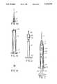
- FIG. 1aillustrates a side elevation view of the needle and hub components of a first embodiment of the syringe
- FIG. 1billustrates a side elevation view of the barrel of a first embodiment of the syringe
- FIG. 1cillustrates a side elevation view of the plunger, bung and hook of a first embodiment of the syringe
- FIG. 1dillustrates an end elevation view of the hook
- FIG. 2illustrates a side elevation partial-section view of a first embodiment of the syringe assembly with the needle and hub secured to an end of the barrel, and the plunger and its bung and hook partially inserted into the interior of the barrel, prior to use of the syringe;
- FIG. 3illustrates a side elevation partial-section view of a first embodiment of the syringe assembly with the plunger and its bung and hook fully inserted into the interior of the barrel so that the hook extends into the interior of hub;
- FIG. 4illustrates a side elevation partial-section view of a first embodiment of the syringe with the plunger, bung, hook and needle fully withdrawn into the interior of the barrel and the distal end of the plunger broken-off from the bung end of the plunger;
- FIG. 5illustrates a side elevation partial section view of an alternative embodiment of the syringe which has a double screw action needle and hub engagement mechanism and the end of the plunger away from the needle and hub engagement mechanism has therein a cavity which can fit over the opening in the end of the plunger after the needle and hub are withdrawn into the interior of the barrel.
- FIG. 6illustrates a detail view of the double screw action needle and hub engagement mechanism.
- FIG. 7illustrates a side elevation partial section view of the needle and hub withdrawn into the interior of the barrel and the broken away part of the plunger placed over the opening in the head end of the barrel.
- FIG. 8illustrates a side elevation partial-section view of a second embodiment of the syringe with a screw-lock plunger-needle hub connection
- FIG. 9illustrates a detailed side elevation partial-section view taken along section A--A of FIG. 11 of a first design of a plunger with a right-hand or left-hand cam-lock rotation to secure the plunger to the needle hub for withdrawing the needle into barrel of the syringe;
- FIG. 10illustrates a detailed side elevation partial-section view taken along section A--A of FIG. 11 of a second design of a plunger with a right-hand or left-hand cam-lock rotation to secure the plunger to the needle hub and a second right-hand or left-hand rotation locking means which provides a double locking action between the plunger and needle hub;
- FIG. 11illustrates an end elevation view of the needle end of the syringe illustrated in FIG. 8;
- FIG. 12is a section view taken along section line B--B of FIG. 9 showing the syringe barrel handle and syringe plunger handle at a 45° angle to one another to activate the right-hand rotation cam locking action;
- FIG. 13illustrates a detailed side elevation partial-section view of side scoring on a plunger of a syringe with an oval flange cam lock
- FIG. 15illustrates a top elevation partial-section view of a plunger with a snap-on socket type needle hub connection
- FIG. 16illustrates a side elevation partial-section view of a plunger with a snap-on socket type needle hub connection
- FIG. 17illustrates a top elevation partial-section view of a plunger with a snap-on socket type needle hub connection combined with a right-hand rotation option
- FIG. 18illustrates a section view taken along section line A--A of FIG. 16;
- FIG. 19illustrates a side elevation partial-section view of a bent needle embodiment of a needle hub connection
- FIG. 20illustrates a top elevation partial-section view of a bent needle embodiment of a needle hub connection
- FIG. 21illustrates a side elevation partial-section view of a bent needle embodiment of a needle hub connection coupled with a right-hand rotation option
- FIG. 22illustrates a detailed end view of the diagonal slot in the end of the piston-plunger with the bent needle end fitted in the slot;
- FIG. 23illustrates a detailed end view of the diagonal slot in the end of the piston-plunger rotated in the slot to grip the bent end of the needle;
- FIG. 24illustrates a side elevation partial-section view of an embodiment of the syringe wherein the needle and hub are rotatably detachable from the barrel and the plunger threadedly engages the interior of the hub;
- FIG. 25aillustrates a side elevation partial-section view of the syringe with the needle and hub drawn within the interior of the barrel and the remote end of the plunger that is broken away, formed with a hollow threaded cap-like opening;
- FIG. 25billustrates a side elevation partial-section view of the syringe with the broken away plunger portion threadedly engaged with the male threaded end of the hub at the top of the barrel.
- FIGS. 25c and 25dillustrate sequential side elevation views of an alternative design of syringe where the part of the plunger adjacent the break away weak point is threaded and is screwed into the opening in the end of the barrel vacated by the needle and hub when pulled into the barrel.
- FIG. 26illustrates a side elevation partial-section view of an embodiment of the syringe wherein the piston is adapted with a latch which snaps into place in an adapter after the piston is fully depressed and rotated.
- FIG. 27illustrates a side elevation partial section view of an adapter which mates with the needle platform.
- FIG. 28illustrates a side elevation section view taken along section line C--C of FIG. 29.
- FIG. 29illustrates an end view of the latch mechanism of the piston depicted in FIG. 26.
- FIG. 30illustrates a side elevation view of an alternative design of adapter
- FIG. 31illustrates a side elevation partial section view of the alternative design of adapter
- FIG. 32illustrates a side elevation partial section view of an embodiment of the syringe wherein an adapter is mounted partially exterior the front end of the syringe to provide a longer length in the barrel.
- Luer connectorwhich may be of two types.
- Oneis a simple conical device which accepts the needle base. This version is often described as a Luer tip. To detach the needle, it is simply pulled off.
- the other connector typeis often described as a Luer lock.
- the Luer lockhas a simple screw thread locking mechanism that permits the base of the needle to be screwed on to the syringe so that it cannot be pulled off without unscrewing.
- the universal coupling mechanism connecting the needle to the syringewill be referred to as a Luer lock version of the Luer connector unless otherwise indicated.
- the claims to the inventionrelate to both the plain Luer tip and the Luer lock mechanisms.
- the interchangability capability of a Luer lockallows for the most appropriate needle to be used for syringe filling and patient injection.
- a different larger needleis used to fill the syringe with fluid prior to injection.
- a needle of fine calibre to minimize pain to the patient, and tissue damage,is often used for intramuscular or subcutaneous injection.
- the same needleis used to puncture a vial in order to fill the syringe with medication, there is a potential for contamination of that needle from the vial, if the vial stopper carries a contaminant. Under most circumstances, this would not pose a significant risk.
- the patienthas reduced immunity to infection, the ability to change to an entirely new sterile needle for patient injection may become important.
- syringeswhich can protect the needle by a variety of means, including those which involve withdrawing the needle into the interior of the barrel of the syringe, such syringes do not allow for interchangability of the needle or for the universal Luer lock coupling mechanism which is an important feature of the syringe.
- Most commercially available syringesemploy a Luer lock. Since the subject invention is adapted for use with a Luer lock, it can directly replace syringes currently in use and requires no change in technique or procedure until after the syringe has been used. In addition, most currently produced needles can be used in the usual manner on this syringe.
- the syringe plungercan be snapped off. It is designed so that it can be screwed onto the front of the syringe and thereby prevent any possibility of the needle within the barrel protruding through the front of the syringe again. This is an important factor for a health care worker using the syringe and also for any healthcare workers subsequently handling garbage which might contain a contaminated syringe.
- This inventionpertains to a syringe which, after being used by a health care worker or hazardous industries worker, or the like, to inject medication or fluid into a patient, or withdraw fluid from a patient, or in sampling toxic material, for example, in an industrial process, can be transformed by the worker to withdraw the needle into the barrel of the syringe for disposal purposes, thereby eliminating potentially harmful needlestick injuries among such workers.
- the storage of a contaminated needleis similarly effected within the barrel to prevent further contamination of the environment or process.
- the needleis retracted by the user into the interior of the body of the syringe immediately after it is withdrawn from the patient's body tissue, or after exposure to hazardous situations.
- the needleis not exposed for accidental contact at any time after the needle has contacted the potentially hazardous patient's body fluids, or other hazardous materials. This retraction feature eliminates the possibility of potentially dangerous needlestick injuries occurring with contaminated needles.
- the safety syringe of the inventionis simple to operate and is only slightly more expensive to manufacture than presently used syringes. Another advantage is that the syringe design closely resembles currently used syringes and thus there should be no difficulty in obtaining good acceptance among workers such as medical institutional workers. Moreover, the operation of the subject syringe is easy to teach to such workers and requires no unusual skills or manual dexterity.
- Syringesthat are in current commercial use normally consist of four components, a needle cap which is removed prior to use, a hollow needle which is mounted on a hub with a Luer lock, a barrel to which the hub is attached, and a plunger with a bung (piston) at the head end of the plunger.
- the plungeris inserted within the barrel head end first and can be pushed into the interior of the barrel in order to pump fluid contained in the barrel out through the interior of the hollow needle.
- the subject inventionin various embodiments, includes several basic modifications which do not dramatically change the appearance of the conventional syringe.
- FIGS. 1a, 1b and 1cillustrate the three basic components which make up a first embodiment of the novel needle retractable syringe.
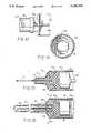
- FIG. 1aillustrates in side elevation partial section view the construction and interaction of the needle 2 and cup 4 which fits detachably within the interior of hub 6 of the syringe.
- Hub 6has a female thread in the base of its interior.
- FIG. 1billustrates in side elevation partial section view the construction interaction of the barrel 8, the partially closed threaded hub receiving end 10, which is located at the top of the barrel 8, and the barrel base 12 which is formed at the bottom the barrel 8.
- a circular rim-like catch 14is formed in the interior of the barrel 8 immediately above the barrel base 12 and provides a stop to deter full withdrawal of the plunger 16 from the interior of the barrel 8.
- the needlemay during manufacture be affixed integrally to the syringe base and be removable only during retraction into the barrel after the syringe has been used.
- FIG. 1cillustrates the construction of the plunger 16, which includes a bung (piston) 18 which fits snuggly against the interior of the barrel 8 and serves to force the liquid contents of the interior of the hollow barrel 8 (usually medication) out the interior of the hollow needle 2, and in a common situation into the body of a patient, when the plunger 16 is manually pushed into the interior of the barrel 8.
- a thumb or finger press 20is formed at the base of the plunger 16, while the base 22 of the bung 18 serves to align the plunger 16 within the interior of the barrel 8, and deter full withdrawal of the plunger 16 from the barrel 8 by abutting catch 14.
- Affixed to the top central area of the bung 18is a five tine metal hook 24.
- FIGS. 2, 3 and 4illustrate in sequential side elevation partial-section views, the syringe in assembled state, with the components in various positions.
- FIG. 2illustrates the syringe assembly when it is charged with a fluid such a fluid medication, or the like, ready for use. The fluid is contained in the volume space immediately above the bung 18 and below the threaded hub receiving end 10.
- the plunger 16When the plunger 16 is fully pushed by thumb or finger press 20 upwardly into the interior of the barrel 8, the fluid contents of the syringe are extruded by plunger 16 and bung 18 through the hollow interior of needle 2 and out the pointed end.
- one or more of the tynes of the hook 24engages with the interior of cup 4 as illustrated in FIG. 3.
- the metal of the needleis extended to form a bell shaped cup 4, which fits within the interior of and is affixed to the plastic hub 6.
- the likelihood that a break will occur between the needle 2 and the cup 4is minimized.
- the needle 2 and the cup 4are formed in one piece, and since the metal is stronger than the plastic forming the hub 6, a break between the metal and the plastic is encouraged.
- the syringe of the inventionhas a built-in safety feature in that the needle 2 can only be withdrawn into the interior of the barrel 8 up to the point that guide 22 abuts the catch 14 located around the interior rim of the base of the barrel 8. Thus, unless considerable effort is exerted, it is not possible to pull the needle 2 cap 4 and plunger 16 completely through the barrel 8.
- the catch 14is designed so that when the components are assembled, it is easy to insert the bung 18, with the hook 24, and the guide 22 through the interior of the one-way catch 14, and into the interior of the barrel 8 but it is difficult to fully withdraw these components.
- the tynes of hook 24are not necessarily of the same length, which encourages tipping of the needle 2 to one side. Breaking off the portion of the plunger 16 that extends beyond barrel base 12 ensures that the used needle 2 cannot be pushed back through hub 6, thereby exposing the sharp point of the needle 2 beyond hub 6. Also, it is usually easier to dispose of two smaller shorter components than one elongated one.
- FIGS. 5 through 31illustrate nine alternative embodiments of the body fluids precautions syringe.
- FIG. 5illustrates a side elevation partial section view of a preferred embodiment of the syringe which has a double screw action needle and hub engagement mechanism 80.
- the end of the plunger 16 away from the needle and hub engagement mechanism 80has therein a cavity 82 which can fit over the cup 84 and opening in the end of the barrel 8 after the needle 2 and hub 6 are withdrawn into the interior of the barrel 8 (See FIG. 7).
- FIG. 6illustrates a detail view of the double screw action needle and hub engagement mechanism 80.
- the mechanism 80is constructed so that it has right hand female thread 86 of one size diameter in a cup-like opening at one side, a right hand female thread 88 of a narrower size diameter in a cup-like opening in the opposite side, and a left-hand male thread 90 on the exterior of the mechanism 80 outside the interior female thread 88.
- Hub 6screws into female thread 88 and the syringe is used in this configuration for injecting medication into a patient.
- the mechanism 80to enable the needle to be withdrawn into the barrel 8, the head end of the plunger and bung 18 are screwed right handed into the female thread 86. Once fully engaged, then further right hand action on left-handed thread 90, unscrews thread 90. The entire mechanism 80 including the needle 2 can then be withdrawn into the interior of the barrel 8.
- the right hand and left hand threadscan, of course, be reversed to operate in the reverse manner, if that is required.
- FIG. 7illustrates a side elevation partial section view of the needle 2 and hub 6 withdrawn into the interior of the barrel 8 and the cavity 82 of the broken away part of the plunger 16 placed over the opening and cup 84 in the head end of the barrel 8.
- FIG. 8illustrates a side elevation partial-section view of a second embodiment of the syringe which is constructed to have a screw-lock plunger-needle hub connection.
- the barrel 8has the syringe plunger 16 disposed therein.
- the plunger 16carries at its frontal end (the left end as seen in FIG. 8) a piston 26 which is constructed of a resilient material such as resilient rubber so that it snugly engages the inner cylindrical surface of the barrel 8.
- the piston 26is connected to the plunger 16 by means of a plunger flange 36.
- the frontal end of the plunger 16is constructed to have therein a cylindrical cavity which has a female thread 28 formed in the wall of the cavity.
- FIG. 8also illustrates piston stop 15 formed in the rear end of the interior of the barrel 8 (the right side as seen in FIG. 8). Piston stop 15 serves the same purpose as catch 14 as discussed in relation to FIGS. 1 to 4 above.
- a cap 32protects the needle 2 and fits over the hub 6. Cap 32, when engaged after the needle 2 is withdrawn prevents exposure of the needle 2 if it is accidentally pushed back through the opening at the forward end of the syringe.
- the plunger 16 and piston 26are disposed within barrel 8 as illustrated in FIG. 8.
- the cap 32is removed and the pointed end of the needle 2 is inserted into the medication.
- female hub thread 34is not engaged in male thread 28.
- the fluid medicationis drawn into the interior of the barrel 8 by suction action created by withdrawing press 20 and plunger 16 from the interior of barrel 8, as is conventional.
- the sharp end of the needle 2is inserted into an appropriate location on the patient.
- the medication that is held within the interior of barrel 8is injected through the interior of needle 2 into the patient by asserting thumb or finger pressure on press 20. Once the medication has been injected into the patient, the piston 26 has moved to the position illustrated in FIG. 8.
- break point 30is an option which need not necessarily be built into plunger 16. Breaking the syringe into two parts permits easy disposal whereas one elongated syringe, with the plunger withdrawn might be difficult to dispose of in certain instances.
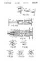
- FIG. 9illustrates a detailed side elevation partial-section view taken along section line A--A of FIG. 11 of a first design of a piston 26 with a right-hand cam-lock rotation (rather than a thread configuration) to secure the forward end of the piston 26 to the needle hub 6 for withdrawing the needle 2 into the barrel of the syringe.
- the cam-lock option illustrated in FIG. 9operates by asserting a right-hand rotation on the press 20, relative to the barrel 8.
- cam-lock ridge 42which is formed in the base of hub 6, rotates into helical engagement with cam-lock groove 44. This combination replaces the male hub thread 34 and female thread 28 combination illustrated in FIG. 8, as discussed previously.
- FIG. 10illustrates a detailed side elevation partial-section view of a second design of a plunger with a right-hand cam-lock rotation (similar to that illustrated in FIG. 9).
- the design shown in FIG. 10also includes a second hub rim 38 which is formed in the base area of hub 6.
- the purpose of hub rim 38is to engage left hand thread 40, which is formed in the interior of the barrel 8, which houses the hub 6.
- the alternative option illustrated in FIG. 10includes the right-hand cam-lock ridge 42, cam-lock groove 44 combination, discussed in association with FIG. 9, but it has a second feature.
- a right-hand male hub rib 38is formed in the exterior of hub 6 forward of cam-lock ridge 42.
- a matching right hand female thread 40is formed in the interior of the forward end of barrel 8, that is, the end which surrounds hub 6.
- cam-lock ridge 42is first engaged in cam-lock groove 44 by clockwise (right hand) rotating press 20 relative to barrel base 12 (see FIG. 8) and then, by means of a second right handed (counterclockwise) rotation, hub rim 38 is engaged within female left hand thread 40.
- the needle 2 and hub 6are then double engaged by two right hand twists and can then be withdrawn into the interior of the barrel 8.
- the double-action engagement mechanismensures proper secure engagement of the plunger and hub.
- FIGS. 9 and 10respectively can be used in any of the alternative embodiments of the invention that are illustrated in FIGS. 11 through 23. It should also be recognized that the double-action locking mechanism illustrated in FIG. 10 can be right-right, left-left, right-left or left-right.
- FIG. 11illustrates an end elevation view of the needle end of the syringe illustrated in FIG. 8, and clearly illustrates the eccentric construction of right-hand cam-lock ridge 42.
- Ridge 42is constructed generally in the form of an oval, the opposite ends of the oval being adapted to engage in the right-hand grooves of the cam-lock groove 44 (see FIG. 9 or 10).
- FIG. 12is a section view taken along section line B--B of FIG. 9 and illustrates the syringe barrel base 12 and the press 20 rotated clockwise 45° relative to one another. This clockwise action engages cam-lock ridge 42 in cam-lock groove 44.
- FIG. 13illustrates in detail a side elevation partial-section view of right-hand side scoring on the interior frontal opening a plunger of the syringe adapted for use with the oval flange cam-lock.
- the right-hand oval shaped ridges 42when they become mated in the interior of the pair of cam-lock grooves 44, rotate relative to one another in a helical fashion, thereby creating a secure fit.
- FIG. 14illustrates a detailed end view of the cam-lock mechanism of the embodiment of the syringe illustrated in FIG. 9. Barrel 8 and cam-lock ridge 42 are shown in solid lines. The dotted lines represent the cam-lock groove 44.
- FIG. 15illustrates a top elevation partial-section view of a plunger 16 which is equipped with an alternative design engaging mechanism, namely a snap-on socket type needle hub connection.
- FIG. 16illustrates a side elevation view of the snap-on socket type needle hub connection illustrated in FIG. 15.
- the forward end of the plunger 16is constructed so that it has a "snap-on" fastener 46, which, when the plunger 16 is pushed strongly (in a leftwardly direction as seen in FIG. 16) snaps over and embraces the longitudinal knob-like end 48 that is formed in the base of hub 6.
- the snap-on fastener 46 and knob 48 engagement combinationis an alternative embodiment which replaces the cam-lock ridge 42 and cam-lock groove 44 combination illustrated in FIGS.
- FIG. 17illustrates the snap-on fastener 46-snap over knob 48 embodiment discussed previously in relation to FIGS. 15 and 16, but includes the option of a right-hand hub rim 38 and a right hand thread 40 secondary engagement mechanism (as discussed in detail previously in association with FIG. 10).
- FIG. 18illustrates a section view of the syringe taken along section line A--A of FIG. 16.
- the rectangular construction of the snap-on fastener 46, which fits over snap over knob 48,can be readily seen.
- the plunger flange 36shown in dotted lines
- barrel 8needle 2
- barrel base 12barrel base 12
- FIGS. 15 to 18illustrate a cylindrical embodiment. It should be understood that alternative shapes such as hexagonal or octagonal can be used. The advantage would be that such a configuration would allow for rotary movement to be transferred to the needle assembly and allow it to be broken away by rotation rather than by simple traction.
- FIGS. 19 and 20illustrate respectively side and top elevation partial-section views of a further alternative engaging mechanism, namely a bent needle hub engaging embodiment of the syringe.
- FIG. 19which depicts the side elevation view, incorporates the first option (that is, without optional hub rim 38, and right hand thread 40 combination).
- FIG. 19shows how the base end of the needle 2 is bent at right angles to form an upwardly projecting end 50.
- the end 50fits into a slot and groove 52, which is formed in the forward end of the plunger 16.
- the end 50engages in slot 52, thereby securely connecting the head end of plunger 16 with hub 6 and needle 2.
- FIG. 21illustrates the bent needle embodiment that was discussed above in relation to FIGS. 19 and 20, but including the option of a hub rim 38, and a right hand thread 40, formed in the hub 6 to provide a double engagement mechanism.
- option 1 or option 2can be utilized in all embodiments of the syringe as discussed.
- FIGS. 22 and 23illustrate a detailed end view of slot 52 and needle end 50, the slot 52 being formed in the head end of the plunger 16.
- the bent needle end 50is first inserted in slot 52, as illustrated in FIG. 22, and then the end 50 is rotated 90° into an groove opening formed in the interior of the plunger 16, thereby engaging the base end of the needle 2 with the plunger 16.
- FIG. 24illustrates a side-elevation partial-section view of an embodiment of the syringe wherein the needle and hub are rotatably detachable from the barrel and the plunger threadedly engages the interior of the hub.
- the base of the needle 2is threadedly and removably engageable with the hub 63 by threads 62.
- the hub 63is threadedly and removably engageable with the barrel 8 by thread 64.
- the head end of the plunger 16can engage with the interior of the hub 63 by interior threads 65 and withdraw needle 2 and hub 63 into the interior of the barrel 8.
- the interior of the head end of barrel 8is shaped like an "M". The angled ends deter the needle 2 from pushing back through the opening in the end of the barrel 8.
- FIG. 25aillustrates a side elevation partial-section view of the syringe with the needle and hub drawn within the interior of the barrel and the remote end of the plunger that is broken away, formed with a hollow threaded cap-like opening;
- FIG. 25billustrates a side-elevation partial-section view of the syringe with the broken away plunger portion threadedly engaged with the male threaded end of the hub at the top of the barrel.
- the hub 6can be formed so that it has male threads 70 around its circumference.
- a mating cavity with mating female thread 72can be formed in the thumb press end of plunger 16. If need be, the thumb press end of plunger 16 can be widened at location 74 in order to accommodate the cavity with the female thread 72.
- the end distant from the thumb press and proximate to the fracture sitecan be fashioned to allow it to fit snuggly or screw into the now open end of the barrel (from which the needle has now been withdrawn into the barrel).
- a second fracture site(not shown) can be fashioned in the plunger. This permits the plunger to be broken off at either of the two fracture sites according to the performance of the user.
- FIGS. 25c and 25dillustrate sequential side elevation views of an alternative design of syringe where the part of the plunger 16 adjacent the break away weak point 30 is threaded 78 and is screwed into female threads 76 of the opening in the end of the barrel 8 vacated by the needle 2 and hub when pulled into the barrel 8.
- FIG. 26illustrates a side elevation partial-section view of an embodiment of the syringe wherein the piston is adapted with a latch which snaps into place in an adapter (platform) after the piston is fully depressed and rotated clockwise.
- the embodiment illustrated in FIG. 26depicts the needle 2 embedded in a Luer lock 100, associated with the constricted end 10 of syringe barrel 8.
- the plunger 16 with a finger press 20 at the remote end thereofis positioned inside barrel 8.
- a stop catch 14prevents the plunger 16 from being totally withdrawn from the interior of the barrel 8.
- Bung 18, which provides a tight fit with the interior of barrel 8,is mounted on the end of plunger 16 opposite finger press 20.
- the operative needle engagement and detachment mechanism illustrated in FIG. 26is a combination of an adapter 102, which cooperates with Luer lock 100, the combination fitting into the narrow end 10 of barrel 8.
- the end of plunger 16 opposite finger press 20has a latch mechanism 104 formed inside bung 18.
- a pair of prongs 106are formed in latch 104 and engage into grooves 108 in adapter 102 when the plunger 16 is rotated in a clockwise direction. Once the pair of prongs 106 engage in the respective grooves 108 of the adapter 102, then the plunger 16 is rotated further clockwise which then, because of the left hand threads 110 engaging the interior of the narrow end 10, causes the adapter, and the needle with the Luer lock 100, to disengage from the narrow end 10. At this point, the needle 2, Luer lock 100, adapter 102, and bung 18 can be withdrawn into the interior of the barrel 8 by pulling finger press 20 away from the narrow end 10 of the syringe.
- the adapter 102is an important feature of this embodiment of the invention.
- the adapterenables a standard Luer lock 100 to indirectly mate with latch 104 at the end of plunger 16.
- the adapter 110is designed so that it accommodates different sizes of needle 2 and Luer lock 100.
- FIG. 26illustrates a narrow point in the plunger which assists in breaking the plunger in two. If required, or desirable, two or more additional narrow points can be included to permit breakage at alternative locations.
- FIG. 27illustrates in side elevation partial section view a preferred embodiment of the adapter 102.
- Nose 112is adapted to fit inside the hollow of a standard Luer lock 100.
- the left hand thread 110is also shown in FIG. 27.
- the adapter 102has opposite the nose 112 a cup-like edge 114 which is formed to receive the front end of latch 104.
- Formed inside the rim of cup 114is a protrusion 116 which has a pair of fast acting spiral male threads 118 formed thereon.
- Prong engaging grooves 108are also formed in the interior of the protrusion 116 at the point where the protrusion 116 joins with the cup 114.
- the advantage of this adapter designis that with the fast acting spiral threads 118 force alignment without jamming.
- FIG. 28illustrates a section view taken along section lines C--C of FIG. 29.
- FIG. 28depicts a detailed view of the construction of the latch 104 and prongs 106.
- the latch 104has a pair of alignment ridges 120 formed in the interior of latch 104. These alignment ridges 120 assist engagement of the latch 104 with adapter 102.
- FIG. 30,which illustrates a side view of an alternative design of adapter 102
- FIG. 31,which illustrates a partial cutaway section view of the adapter depicted in FIG. 30, illustrate flared grooves 122, which are adapted to receive ridges 120 of latch 104.
- the flareassists in enabling the ridges 120 to be received into grooves 122.
- the adapterdoes not have the fast acting non-jamming spiral threads 118, depicted in the adapter design illustrated in FIG. 27.
- FIGS. 26 to 31have a number of advantages:
- the preferred embodimentallows for universal coupling with all Luer lock needle connections.
- Needle interchangeability during use of the syringeis possible, that is, different needles can be used for filling the vial and for injecting the patient.
- the needle platform (adapter) designallows for compatibility of the syringe with other custom design needles or any subsequent needle design, merely by altering the outer needle connection configuration platform.
- the syringe hubcan be permanently closed after use of the syringe by screwing on the broken plunger stalk after withdrawal of the needle into the barrel.
- the novel coupling mechanism between the platform and the plungerallows full axial movement of the plunger without the possibility of an inadvertent locking. But deliberate rotational action permits locking of the coupling device and withdrawal of the platform (adapter) with the attached needle into the barrel.
- FIG. 32illustrates a side elevation partial side section view of an embodiment of the invention related to that illustrated in FIGS. 26 to 30.
- the embodiment depicted in FIG. 32shows an adapter 130 which extends partially from the front end of the barrel 132.
- a standard Luer lock 134is formed in the front end of the barrel 132.
- the Luer lockhas a standard right hand thread 135.
- the barrel 132has a left hand thread 137 to release the adapter 130 for withdrawal inside the barrel 132, after the syringe is used.
- a needle hub 136 carrying needle 140fits on the tapered front end of adapter 130 and screws into the right hand thread of the Luer lock 134.
- a given clearance 138permits the needle hub 136 to be withdrawn into the interior of the barrel 132 after the adapter 130, hub 136, and needle 140 are unscrewed and withdrawn into the barrel 132 by rotation of the plunger and engagement of the plunger adapter connection mechanism.
- a Luer tipmay be a simple conical device which accepts the needle base. This design could also be used in this embodiment, thus eliminating the screw connection of the needle hub 136 and the Luer lock thread 135.
- the adapter 130by partially protruding from the front of the syringe, provides a longer internal barrel length to accommodate longer needles.
- Another advantageis that by reducing the diameter of the platform needle combination, a thinner barrel can be manufactured. For a given capacity of syringe, this will allow the length of the syringe to be longer and therefore a longer needle to be accommodated within it.
- the outer diameter of the platform needle combinationis defined by the width of the needle hub and not by the supporting outer plastic Luer lock mechanism. It is therefore possible to ensure as long a barrel as possible for a given capacity.
- the standard 3 cc syringerepresents a main portion of the syringe market.
- a standard 3 cc syringeis often used with a 11/2 inch needle for intramuscular injection. Accordingly, the barrel of a 3 cc syringe should be at least 21/2 inches long to accommodate the withdrawn needle, adapter and plunger connector all within the barrel. This is done by having the adapter protrude somewhat as shown in FIG. 32.
- the foregoing embodimentsdiscuss various means of enabling the plunger to be connected securely to the hub 6 of the needle 2, to enable the plunger 16, when withdrawn, to pull the hub 6 and needle 2 into the interior of the barrel 8.
- the adapterdisengages if it (the plunger connector) is twisted in the wrong direction. This provides an overtightening safety feature. The adapter is released from the syringe if the correct rotation is used. It will be recognized that these are illustrative of specific embodiments and there are other possible ways to make a secure connection for the purpose of withdrawing the hub and needle into the interior of the barrel
Landscapes
- Health & Medical Sciences (AREA)
- Life Sciences & Earth Sciences (AREA)
- Veterinary Medicine (AREA)
- Engineering & Computer Science (AREA)
- Public Health (AREA)
- General Health & Medical Sciences (AREA)
- Animal Behavior & Ethology (AREA)
- Biomedical Technology (AREA)
- Hematology (AREA)
- Heart & Thoracic Surgery (AREA)
- Anesthesiology (AREA)
- Vascular Medicine (AREA)
- Epidemiology (AREA)
- Environmental & Geological Engineering (AREA)
- Infusion, Injection, And Reservoir Apparatuses (AREA)
- Facsimiles In General (AREA)
Abstract
Description
Claims (36)
Priority Applications (25)
| Application Number | Priority Date | Filing Date | Title |
|---|---|---|---|
| US07/410,318US5030208A (en) | 1989-03-22 | 1989-09-21 | Safety syringe needle device with interchangeable and retractable needle platform |
| JP2505740AJP2828175B2 (en) | 1989-03-22 | 1990-03-20 | Syringe with replaceable and retractable needle platform |
| AU54202/90AAU638009C (en) | 1989-03-22 | 1990-03-20 | Syringe with interchangeable and retractable needle platform |
| AT9090905392TATE105493T1 (en) | 1989-03-22 | 1990-03-20 | SYRINGE WITH INTERCHANGEABLE AND RETRACTABLE NEEDLE PLATFORM. |
| ES90905392TES2056461T3 (en) | 1989-03-22 | 1990-03-20 | SYRINGE WITH INTERCHANGEABLE AND REMOVABLE NEEDLE PLATFORM. |
| DK90905392.8TDK0463086T3 (en) | 1989-03-22 | 1990-03-20 | Replaceable and retractable needle platform syringe |
| DE69008850TDE69008850T2 (en) | 1989-03-22 | 1990-03-20 | SYRINGE WITH INTERCHANGEABLE AND RETRACTABLE CANNULA PLATFORM. |
| CA002049972ACA2049972C (en) | 1989-03-22 | 1990-03-20 | Syringe with interchangeable and retractable needle platform |
| PCT/CA1990/000095WO1990011099A1 (en) | 1989-03-22 | 1990-03-20 | Syringe with interchangeable and retractable needle platform |
| BR909007247ABR9007247A (en) | 1989-03-22 | 1990-03-20 | SYRINGE WITH INTERCHANGEABLE AND RETRACTILE NEEDLE PLATFORM |
| EP90905392AEP0463086B1 (en) | 1989-03-22 | 1990-03-20 | Syringe with interchangeable and retractable needle platform |
| US07/607,127US5122124A (en) | 1988-12-14 | 1990-10-03 | Safety syringe needle device with interchangeable and retractable needle platform |
| US07/800,849US5205827A (en) | 1988-12-14 | 1991-11-29 | Safety syringe needle device with interchangeable and retractable needle platform |
| US07/909,385US5263933A (en) | 1988-12-14 | 1992-07-08 | Safety syringe needle device with interchangeable and retractable needle platform |
| US08/128,694US5415638A (en) | 1988-12-14 | 1993-09-30 | Safety syringe needle device with interchangeable and retractable needle platform |
| US08/136,201US5360404A (en) | 1988-12-14 | 1993-10-15 | Needle guard and needle assembly for syringe |
| US08/361,227US5462531A (en) | 1988-12-14 | 1994-12-21 | Safety syringe needle device with interchangeable and retractable needle platform |
| US08/470,026US5520649A (en) | 1988-12-14 | 1995-06-06 | Safety syringe needle device with interchangeable and retractable needle platform |
| US08/603,868US5688240A (en) | 1988-12-14 | 1996-02-22 | Safety syringe needle device with interchangeable and retractable needle platform |
| US08/917,337US5858000A (en) | 1988-12-14 | 1997-08-25 | Safety syringe needle device with interchangeable and retractable needle platform |
| US09/215,519US6033386A (en) | 1988-12-14 | 1998-12-18 | Safety syringe needle device with interchangeable and retractable needle platform |
| US09/460,713US6117113A (en) | 1988-12-14 | 1999-12-14 | Safety syringe needle device with interchangeable and retractable needle platform |
| US09/637,873US6344031B1 (en) | 1989-03-22 | 2000-08-15 | Safety syringe needle device with interchangeable and retractable needle platform |
| US10/042,355US6878131B2 (en) | 1988-12-14 | 2002-01-11 | Safety syringe needle device with interchangeable and retractable needle platform |
| US10/766,034US20050192541A1 (en) | 1988-12-14 | 2004-01-29 | Safety syringe needle device with interchangeable and retractable needle platform |
Applications Claiming Priority (2)
| Application Number | Priority Date | Filing Date | Title |
|---|---|---|---|
| US32734489A | 1989-03-22 | 1989-03-22 | |
| US07/410,318US5030208A (en) | 1989-03-22 | 1989-09-21 | Safety syringe needle device with interchangeable and retractable needle platform |
Related Parent Applications (1)
| Application Number | Title | Priority Date | Filing Date |
|---|---|---|---|
| US32734489AContinuation-In-Part | 1988-12-14 | 1989-03-22 |
Related Child Applications (2)
| Application Number | Title | Priority Date | Filing Date |
|---|---|---|---|
| US07/607,127Continuation-In-PartUS5122124A (en) | 1988-12-14 | 1990-10-03 | Safety syringe needle device with interchangeable and retractable needle platform |
| US07/687,108Continuation-In-PartUS5112318A (en) | 1988-12-14 | 1991-04-18 | Safety syringe needle device with interchangeable and retractable needle platform |
Publications (1)
| Publication Number | Publication Date |
|---|---|
| US5030208Atrue US5030208A (en) | 1991-07-09 |
Family
ID=26985828
Family Applications (1)
| Application Number | Title | Priority Date | Filing Date |
|---|---|---|---|
| US07/410,318Expired - LifetimeUS5030208A (en) | 1988-12-14 | 1989-09-21 | Safety syringe needle device with interchangeable and retractable needle platform |
Country Status (10)
| Country | Link |
|---|---|
| US (1) | US5030208A (en) |
| EP (1) | EP0463086B1 (en) |
| JP (1) | JP2828175B2 (en) |
| AT (1) | ATE105493T1 (en) |
| BR (1) | BR9007247A (en) |
| CA (1) | CA2049972C (en) |
| DE (1) | DE69008850T2 (en) |
| DK (1) | DK0463086T3 (en) |
| ES (1) | ES2056461T3 (en) |
| WO (1) | WO1990011099A1 (en) |
Cited By (54)
| Publication number | Priority date | Publication date | Assignee | Title |
|---|---|---|---|---|
| US5125908A (en)* | 1990-10-19 | 1992-06-30 | Cohen Milton J | Hypodermic syringe with protective holder |
| US5171300A (en)* | 1988-02-01 | 1992-12-15 | Medtech Group, Inc. | Disposable hypodermic syringe |
| US5188597A (en)* | 1992-04-13 | 1993-02-23 | Becton, Dickinson And Company | Safety needle syringe |
| US5188601A (en)* | 1991-11-06 | 1993-02-23 | King Richard J | Disposable safety syringe |
| US5195985A (en)* | 1990-05-25 | 1993-03-23 | Hall John E | Syringe having a retractable needle |
| WO1993006880A1 (en)* | 1991-10-04 | 1993-04-15 | Retrax, Inc. | Retractable syringe |
| US5205823A (en)* | 1990-10-04 | 1993-04-27 | Retrax, Inc. | Retractable syringe |
| US5205824A (en)* | 1991-06-13 | 1993-04-27 | Mazur Matthew S | Retractable syringe with a closed barrel |
| US5256151A (en)* | 1989-06-15 | 1993-10-26 | Mediverse, Inc. | Safety syringe with retractible needle holder |
| EP0566882A1 (en)* | 1992-03-25 | 1993-10-27 | Demetrio Federico | Safety syringe |
| US5263933A (en)* | 1988-12-14 | 1993-11-23 | Patco Ventures Ltd. | Safety syringe needle device with interchangeable and retractable needle platform |
| US5336186A (en)* | 1993-02-10 | 1994-08-09 | Habley Medical Technology Corporation | Safety syringe with displaceable barrel hub |
| US5336198A (en)* | 1993-02-01 | 1994-08-09 | Innova Development Corp. | Hypodermic syringe with needle retraction feature |
| US5346480A (en)* | 1992-12-14 | 1994-09-13 | Q-Med, Inc. | Syringe with retractable needle |
| US5352208A (en)* | 1992-11-30 | 1994-10-04 | Robinson Wilbur D | Safe non-reusable hypodermic syringe |
| US5370619A (en)* | 1989-12-20 | 1994-12-06 | Rossi; Lucio | Single-use safety syringe provided with retractile needle and device preventing it from being reused |
| US5401246A (en)* | 1991-06-13 | 1995-03-28 | U.S. Medical Instruments, Inc. | Retractable syringe with a closed barrel |
| US5415638A (en)* | 1988-12-14 | 1995-05-16 | Inviro Medical Devices, Ltd. | Safety syringe needle device with interchangeable and retractable needle platform |
| US5462531A (en)* | 1988-12-14 | 1995-10-31 | Inviro Medical Devices Ltd. | Safety syringe needle device with interchangeable and retractable needle platform |
| GB2298139A (en)* | 1994-10-21 | 1996-08-28 | Lu Wen Chin | Safety syringe |
| WO1999025403A1 (en)* | 1997-11-14 | 1999-05-27 | Manuel Valle Sanchez | Improved syringe with incorporated locking system of the single use or non reusable type |
| US5951520A (en)* | 1996-12-19 | 1999-09-14 | Bio-Plexus, Inc. | Self-blunting needle medical devices and methods of manufacture thereof |
| US6146337A (en)* | 1998-11-25 | 2000-11-14 | Bio-Plexus, Inc. | Holder for blood collection needle with blunting mechanism |
| US6183464B1 (en) | 1998-06-01 | 2001-02-06 | Inviro Medical Devices Ltd. | Safety syringe with retractable needle and universal luer coupling |
| US6488657B1 (en)* | 2001-09-21 | 2002-12-03 | M.K. Meditech Co., Ltd. | Needle holder positioning structure for safety hypodermic syringe |
| US6524278B1 (en) | 1998-09-04 | 2003-02-25 | Nmt Group Plc | Needle sheath |
| US6530903B2 (en) | 2000-02-24 | 2003-03-11 | Xiping Wang | Safety syringe |
| WO2003072181A1 (en)* | 2002-02-27 | 2003-09-04 | Van Dyke Lewis R | Automatically retractable needle safety syringe |
| US20030236501A1 (en)* | 1998-09-04 | 2003-12-25 | Donnan Jeremy Francis | Retractable needle syringe including a sheath and an intravenous adapter |
| US6733465B1 (en) | 1998-11-25 | 2004-05-11 | Bio-Plexus, Inc. | Holder for blood collection needle with blunting mechanism |
| US20040153113A1 (en)* | 2000-03-15 | 2004-08-05 | Matera James R. | Surgical tattooing apparatus and method |
| US6805689B2 (en) | 2001-10-23 | 2004-10-19 | Wei Chen | Safety blood collector device |
| US20060089597A1 (en)* | 2004-10-21 | 2006-04-27 | Allard Edward F | Hypodermic syringe with multi-gauge needle exchangeability |
| US20060241515A1 (en)* | 2005-04-21 | 2006-10-26 | Jones Jeffrey L | Single-hand operated syringe-like device that provides electronic chain of custody when securing a sample for analysis |
| US20080097303A1 (en)* | 2006-06-02 | 2008-04-24 | Chih-Hsiung Chen | Syringe with retractable needle |
| US20080255524A1 (en)* | 2007-04-11 | 2008-10-16 | Vantex Biotechnology Co., Ltd. | Structure of the syringe cover including the barrel |
| US20100076378A1 (en)* | 2007-03-21 | 2010-03-25 | Midland Medical Devices Holdings, Llc | Safety Medical Syringe with Retractable Needle and Including a Plunger that is Received within a Barrel |
| US7803132B2 (en) | 2004-10-14 | 2010-09-28 | Midland Medical Device Holdings, LLC | Safety medical syringe with retractable needle |
| US7846135B2 (en) | 2006-02-24 | 2010-12-07 | Midland Medical Holding LLC | Retractable needle syringe with needle trap |
| US7985216B2 (en) | 2004-03-16 | 2011-07-26 | Dali Medical Devices Ltd. | Medicinal container engagement and automatic needle device |
| US8376998B2 (en) | 2003-09-17 | 2013-02-19 | Elcam Medical Agricultural Cooperative Association Ltd. | Automatic injection device |
| US20130060191A1 (en)* | 2009-11-11 | 2013-03-07 | Unitract Syringe Pty Ltd | Vaccination syringe |
| US8486024B2 (en) | 2011-04-27 | 2013-07-16 | Covidien Lp | Safety IV catheter assemblies |
| US8628497B2 (en) | 2011-09-26 | 2014-01-14 | Covidien Lp | Safety catheter |
| US8715250B2 (en) | 2011-09-26 | 2014-05-06 | Covidien Lp | Safety catheter and needle assembly |
| US20140124508A1 (en)* | 2012-11-08 | 2014-05-08 | Sulzer Mixpac Ag | Cartridge for at least two flowable components |
| WO2014127095A1 (en)* | 2013-02-13 | 2014-08-21 | Castillo Hilario | Multiple needle syringe |
| US8834422B2 (en) | 2011-10-14 | 2014-09-16 | Covidien Lp | Vascular access assembly and safety device |
| US20140296744A1 (en)* | 2011-10-20 | 2014-10-02 | Becton, Dickinson And Company | Syringe with Removable Plunger for Arterial Blood Gas Sample Collection |
| US8864783B2 (en) | 2005-08-04 | 2014-10-21 | Bayer Healthcare Llc | Lancing device |
| US8939938B2 (en) | 2006-10-12 | 2015-01-27 | Covidien Lp | Needle tip protector |
| EP3144019A4 (en)* | 2014-05-14 | 2018-02-14 | Dongkoo Bio & Pharma Co., Ltd. | Component separator |
| EP3599032A1 (en)* | 2018-07-26 | 2020-01-29 | Nordson Corporation | Dispensing tube for dispensing liquid materials |
| US10774301B2 (en) | 2016-07-11 | 2020-09-15 | Board Of Trustees Of Southern Illinois University | Syringe system for fluid separation |
Families Citing this family (16)
| Publication number | Priority date | Publication date | Assignee | Title |
|---|---|---|---|---|
| US6344031B1 (en) | 1989-03-22 | 2002-02-05 | Laurel A. Novacek | Safety syringe needle device with interchangeable and retractable needle platform |
| US5858000A (en)* | 1988-12-14 | 1999-01-12 | Inviro Medical Devices Ltd. | Safety syringe needle device with interchangeable and retractable needle platform |
| US5122124A (en)* | 1988-12-14 | 1992-06-16 | Patco Ventures Ltd. | Safety syringe needle device with interchangeable and retractable needle platform |
| US5112318A (en)* | 1990-10-03 | 1992-05-12 | Patco Ventures Ltd. | Safety syringe needle device with interchangeable and retractable needle platform |
| DE69024815T2 (en) | 1989-09-18 | 1996-05-23 | Robb Pascal Patent Pty. Ltd., Alderley, Queensland | SYRINGE |
| DK285990A (en)* | 1990-11-30 | 1992-05-31 | Nujenko Pty Ltd | SPRAY UNIT |
| US5776076A (en)* | 1996-03-11 | 1998-07-07 | Chen; Long-Hsiung | Safety vacuum syringe for blood sampling |
| CN101203253A (en)* | 2005-05-11 | 2008-06-18 | 医疗器械创新有限公司 | A syringe with removable needle |
| DE102005052545A1 (en)* | 2005-11-02 | 2007-05-03 | Schering Ag | Closure for medical syringe, has syringe cylinder and connected syringe neck at distal end whereby syringe neck has fixable adapter in which screw cap is fixable |
| JP2011041689A (en)* | 2009-08-21 | 2011-03-03 | Top Corp | Medical needle with protector |
| WO2011057334A1 (en)* | 2009-11-11 | 2011-05-19 | Unitract Syringe Pty Ltd | Clinical syringe |
| WO2012157313A1 (en)* | 2011-05-13 | 2012-11-22 | テルモ株式会社 | Injection needle unit |
| WO2012157312A1 (en)* | 2011-05-13 | 2012-11-22 | テルモ株式会社 | Injection needle unit |
| US11213631B2 (en) | 2017-06-13 | 2022-01-04 | Difinity Solutions Inc. | Protected needle assembly for a hypodermic needle |
| US11759570B2 (en) | 2019-02-25 | 2023-09-19 | Difinity Solutions Inc. | Medicament injector and interchangeable cartridges therefor |
| EP4351366A1 (en)* | 2021-06-11 | 2024-04-17 | Nicoventures Trading Limited | Aerosol provision device |
Citations (40)
| Publication number | Priority date | Publication date | Assignee | Title |
|---|---|---|---|---|
| US2688325A (en)* | 1952-09-12 | 1954-09-07 | Compule Corp | Piston plug withdrawal limiting means for hypodermic syringe devices and the like |
| US3306290A (en)* | 1964-02-14 | 1967-02-28 | Harold S Weltman | Automatically retractable needle syringe |
| US3354882A (en)* | 1964-10-26 | 1967-11-28 | Pharmaseal Lab | Hypodermic syringe |
| GB1150980A (en)* | 1966-08-19 | 1969-05-07 | Sven Husted-Andersen | Disposable Syringe |
| US3884230A (en)* | 1973-09-27 | 1975-05-20 | Goldwyn L Wulff | Flexible needle and guard device for a hypodermic syringe |
| US3930492A (en)* | 1974-08-21 | 1976-01-06 | Jintan Terumo Company, Ltd. | Air-noncontact type blood sampling assembly |
| US4085737A (en)* | 1976-09-03 | 1978-04-25 | Bordow Richard A | Device and technique for minimizing risk of contamination by blood sample |
| US4139009A (en)* | 1976-11-23 | 1979-02-13 | Marcial Alvarez | Hypodermic needle assembly with retractable needle cover |
| US4258713A (en)* | 1979-07-23 | 1981-03-31 | Wardlaw Stephen C | Automatic disposable hypodermic syringe |
| US4266543A (en)* | 1979-02-22 | 1981-05-12 | Blum Alvin S | Hypodermic needle protection means |
| US4266544A (en)* | 1979-11-09 | 1981-05-12 | Wardlaw Stephen C | Hypodermic syringe |
| US4425120A (en)* | 1982-04-15 | 1984-01-10 | Sampson Norma A | Shielded hypodermic syringe |
| US4459997A (en)* | 1981-11-03 | 1984-07-17 | Walter Sarstedt Kunststoff-Spritzgusswerk | Blood extracting and centrifuging device |
| US4542749A (en)* | 1981-09-30 | 1985-09-24 | Ivo Caselgrandi | Syringe for use in hypodermic biopsy, featuring automatic plunger-return |
| US4562844A (en)* | 1984-11-27 | 1986-01-07 | Jett Labs, Inc. | Multipurpose syringe |
| US4573976A (en)* | 1984-05-24 | 1986-03-04 | Dolores A. Smith | Shielded needle |
| US4592744A (en)* | 1985-08-14 | 1986-06-03 | The University Of Virginia Alumni Patents Foundation | Self-resheathing needle assembly |
| US4631057A (en)* | 1985-12-17 | 1986-12-23 | Dolores A. Smith | Shielded needle |
| US4650468A (en)* | 1986-02-26 | 1987-03-17 | Jennings Jr Baldwin P | Medical syringe |
| US4655751A (en)* | 1986-02-14 | 1987-04-07 | Harbaugh John T | Liquid dispensing and receiving syringe |
| US4675005A (en)* | 1986-05-08 | 1987-06-23 | Deluccia James | Retractable disposable syringe |
| US4692156A (en)* | 1985-12-06 | 1987-09-08 | Irene Haller | Disposable syringe with retractable cannula |
| US4695274A (en)* | 1986-01-31 | 1987-09-22 | Fox Richard L | Protected hypodermic needle |
| US4710170A (en)* | 1987-02-12 | 1987-12-01 | Habley Medical Technology Corporation | Anti-needle strike and anti-drug abuse syringe |
| US4747830A (en)* | 1986-04-28 | 1988-05-31 | Gloyer Walter W | Anti-stick contagion free disposable hypodermic safety syringe |
| US4770655A (en)* | 1987-03-13 | 1988-09-13 | Habley Medical Technology Corporation | Disease control syringe having a retractable needle |
| US4774964A (en)* | 1987-11-18 | 1988-10-04 | Applied Plastics Technology, Inc. | Disposable blood collection device |
| US4790828A (en)* | 1987-08-07 | 1988-12-13 | Dombrowski Mitchell P | Self-capping needle assembly |
| US4790822A (en)* | 1987-12-11 | 1988-12-13 | Haining Michael L | Retractable hypodermic safety syringe |
| US4795443A (en)* | 1987-04-16 | 1989-01-03 | Peachtree Medical, Inc. | Syringe sealing device and method |
| US4804370A (en)* | 1987-03-13 | 1989-02-14 | Habley Medical Technology Corporation | Disease control syringe having a retractable needle |
| US4810248A (en)* | 1986-02-03 | 1989-03-07 | Masters Edwin J | Syringe with safety sheath and safety needle cap |
| US4813426A (en)* | 1987-11-09 | 1989-03-21 | Habley Medical Technology Corporation | Shielded safety syringe having a retractable needle |
| US4813936A (en)* | 1988-01-20 | 1989-03-21 | Geralyn M. Schroeder | Retracting hypodermic needle |
| US4832695A (en)* | 1985-09-23 | 1989-05-23 | Bruce Rosenberg | Tamper evident injection syringe |
| US4838870A (en)* | 1987-06-08 | 1989-06-13 | Sherwood Medical Co. | Removable needle attachment having a detachable needle |
| US4861338A (en)* | 1988-02-11 | 1989-08-29 | Mediverse Inc. | Safety syringe |
| US4874383A (en)* | 1987-03-17 | 1989-10-17 | Mcnaughton R David | Syringe shield |
| EP0347742A1 (en)* | 1988-06-23 | 1989-12-27 | Aldo Venturini | Disposable safety syringe |
| WO1989012475A1 (en)* | 1988-06-15 | 1989-12-28 | Alteron Incorporated | Syringe with retractable needle |
Family Cites Families (1)
| Publication number | Priority date | Publication date | Assignee | Title |
|---|---|---|---|---|
| US4986813A (en)* | 1988-02-01 | 1991-01-22 | The MadTech Group, Inc. | Disposable hypodermic syringe |
- 1989
- 1989-09-21USUS07/410,318patent/US5030208A/ennot_activeExpired - Lifetime
- 1990
- 1990-03-20WOPCT/CA1990/000095patent/WO1990011099A1/enactiveIP Right Grant
- 1990-03-20CACA002049972Apatent/CA2049972C/ennot_activeExpired - Lifetime
- 1990-03-20ATAT9090905392Tpatent/ATE105493T1/ennot_activeIP Right Cessation
- 1990-03-20EPEP90905392Apatent/EP0463086B1/ennot_activeExpired - Lifetime
- 1990-03-20BRBR909007247Apatent/BR9007247A/ennot_activeIP Right Cessation
- 1990-03-20ESES90905392Tpatent/ES2056461T3/ennot_activeExpired - Lifetime
- 1990-03-20JPJP2505740Apatent/JP2828175B2/ennot_activeExpired - Fee Related
- 1990-03-20DEDE69008850Tpatent/DE69008850T2/ennot_activeExpired - Fee Related
- 1990-03-20DKDK90905392.8Tpatent/DK0463086T3/enactive
Patent Citations (41)
| Publication number | Priority date | Publication date | Assignee | Title |
|---|---|---|---|---|
| US2688325A (en)* | 1952-09-12 | 1954-09-07 | Compule Corp | Piston plug withdrawal limiting means for hypodermic syringe devices and the like |
| US3306290A (en)* | 1964-02-14 | 1967-02-28 | Harold S Weltman | Automatically retractable needle syringe |
| US3354882A (en)* | 1964-10-26 | 1967-11-28 | Pharmaseal Lab | Hypodermic syringe |
| GB1150980A (en)* | 1966-08-19 | 1969-05-07 | Sven Husted-Andersen | Disposable Syringe |
| US3884230A (en)* | 1973-09-27 | 1975-05-20 | Goldwyn L Wulff | Flexible needle and guard device for a hypodermic syringe |
| US3930492A (en)* | 1974-08-21 | 1976-01-06 | Jintan Terumo Company, Ltd. | Air-noncontact type blood sampling assembly |
| US4085737A (en)* | 1976-09-03 | 1978-04-25 | Bordow Richard A | Device and technique for minimizing risk of contamination by blood sample |
| US4139009A (en)* | 1976-11-23 | 1979-02-13 | Marcial Alvarez | Hypodermic needle assembly with retractable needle cover |
| US4266543A (en)* | 1979-02-22 | 1981-05-12 | Blum Alvin S | Hypodermic needle protection means |
| US4258713A (en)* | 1979-07-23 | 1981-03-31 | Wardlaw Stephen C | Automatic disposable hypodermic syringe |
| US4266544A (en)* | 1979-11-09 | 1981-05-12 | Wardlaw Stephen C | Hypodermic syringe |
| US4542749A (en)* | 1981-09-30 | 1985-09-24 | Ivo Caselgrandi | Syringe for use in hypodermic biopsy, featuring automatic plunger-return |
| US4459997A (en)* | 1981-11-03 | 1984-07-17 | Walter Sarstedt Kunststoff-Spritzgusswerk | Blood extracting and centrifuging device |
| US4425120A (en)* | 1982-04-15 | 1984-01-10 | Sampson Norma A | Shielded hypodermic syringe |
| US4573976A (en)* | 1984-05-24 | 1986-03-04 | Dolores A. Smith | Shielded needle |
| US4562844A (en)* | 1984-11-27 | 1986-01-07 | Jett Labs, Inc. | Multipurpose syringe |
| US4592744A (en)* | 1985-08-14 | 1986-06-03 | The University Of Virginia Alumni Patents Foundation | Self-resheathing needle assembly |
| US4832695A (en)* | 1985-09-23 | 1989-05-23 | Bruce Rosenberg | Tamper evident injection syringe |
| US4692156A (en)* | 1985-12-06 | 1987-09-08 | Irene Haller | Disposable syringe with retractable cannula |
| US4631057A (en)* | 1985-12-17 | 1986-12-23 | Dolores A. Smith | Shielded needle |
| US4695274A (en)* | 1986-01-31 | 1987-09-22 | Fox Richard L | Protected hypodermic needle |
| US4810248A (en)* | 1986-02-03 | 1989-03-07 | Masters Edwin J | Syringe with safety sheath and safety needle cap |
| US4655751A (en)* | 1986-02-14 | 1987-04-07 | Harbaugh John T | Liquid dispensing and receiving syringe |
| US4650468A (en)* | 1986-02-26 | 1987-03-17 | Jennings Jr Baldwin P | Medical syringe |
| US4747830A (en)* | 1986-04-28 | 1988-05-31 | Gloyer Walter W | Anti-stick contagion free disposable hypodermic safety syringe |
| US4675005A (en)* | 1986-05-08 | 1987-06-23 | Deluccia James | Retractable disposable syringe |
| US4710170A (en)* | 1987-02-12 | 1987-12-01 | Habley Medical Technology Corporation | Anti-needle strike and anti-drug abuse syringe |
| EP0278493A2 (en)* | 1987-02-12 | 1988-08-17 | Habley Medical Technology Corporation | Anti-needle strike and anti-drug abuse syringe |
| US4770655A (en)* | 1987-03-13 | 1988-09-13 | Habley Medical Technology Corporation | Disease control syringe having a retractable needle |
| US4804370A (en)* | 1987-03-13 | 1989-02-14 | Habley Medical Technology Corporation | Disease control syringe having a retractable needle |
| US4874383A (en)* | 1987-03-17 | 1989-10-17 | Mcnaughton R David | Syringe shield |
| US4795443A (en)* | 1987-04-16 | 1989-01-03 | Peachtree Medical, Inc. | Syringe sealing device and method |
| US4838870A (en)* | 1987-06-08 | 1989-06-13 | Sherwood Medical Co. | Removable needle attachment having a detachable needle |
| US4790828A (en)* | 1987-08-07 | 1988-12-13 | Dombrowski Mitchell P | Self-capping needle assembly |
| US4813426A (en)* | 1987-11-09 | 1989-03-21 | Habley Medical Technology Corporation | Shielded safety syringe having a retractable needle |
| US4774964A (en)* | 1987-11-18 | 1988-10-04 | Applied Plastics Technology, Inc. | Disposable blood collection device |
| US4790822A (en)* | 1987-12-11 | 1988-12-13 | Haining Michael L | Retractable hypodermic safety syringe |
| US4813936A (en)* | 1988-01-20 | 1989-03-21 | Geralyn M. Schroeder | Retracting hypodermic needle |
| US4861338A (en)* | 1988-02-11 | 1989-08-29 | Mediverse Inc. | Safety syringe |
| WO1989012475A1 (en)* | 1988-06-15 | 1989-12-28 | Alteron Incorporated | Syringe with retractable needle |
| EP0347742A1 (en)* | 1988-06-23 | 1989-12-27 | Aldo Venturini | Disposable safety syringe |
Cited By (76)
| Publication number | Priority date | Publication date | Assignee | Title |
|---|---|---|---|---|
| US5171300A (en)* | 1988-02-01 | 1992-12-15 | Medtech Group, Inc. | Disposable hypodermic syringe |
| US5688240A (en)* | 1988-12-14 | 1997-11-18 | Inviro Medical Devices Ltd. | Safety syringe needle device with interchangeable and retractable needle platform |
| US5520649A (en)* | 1988-12-14 | 1996-05-28 | Inviro Medical Devices Ltd. | Safety syringe needle device with interchangeable and retractable needle platform |
| US5462531A (en)* | 1988-12-14 | 1995-10-31 | Inviro Medical Devices Ltd. | Safety syringe needle device with interchangeable and retractable needle platform |
| US5415638A (en)* | 1988-12-14 | 1995-05-16 | Inviro Medical Devices, Ltd. | Safety syringe needle device with interchangeable and retractable needle platform |
| US5263933A (en)* | 1988-12-14 | 1993-11-23 | Patco Ventures Ltd. | Safety syringe needle device with interchangeable and retractable needle platform |
| US5256151A (en)* | 1989-06-15 | 1993-10-26 | Mediverse, Inc. | Safety syringe with retractible needle holder |
| US5370619A (en)* | 1989-12-20 | 1994-12-06 | Rossi; Lucio | Single-use safety syringe provided with retractile needle and device preventing it from being reused |
| US5195985A (en)* | 1990-05-25 | 1993-03-23 | Hall John E | Syringe having a retractable needle |
| US5205823A (en)* | 1990-10-04 | 1993-04-27 | Retrax, Inc. | Retractable syringe |
| US5125908A (en)* | 1990-10-19 | 1992-06-30 | Cohen Milton J | Hypodermic syringe with protective holder |
| US5401246A (en)* | 1991-06-13 | 1995-03-28 | U.S. Medical Instruments, Inc. | Retractable syringe with a closed barrel |
| US5205824A (en)* | 1991-06-13 | 1993-04-27 | Mazur Matthew S | Retractable syringe with a closed barrel |
| WO1993006880A1 (en)* | 1991-10-04 | 1993-04-15 | Retrax, Inc. | Retractable syringe |
| US5188601A (en)* | 1991-11-06 | 1993-02-23 | King Richard J | Disposable safety syringe |
| EP0566882A1 (en)* | 1992-03-25 | 1993-10-27 | Demetrio Federico | Safety syringe |
| US5188597A (en)* | 1992-04-13 | 1993-02-23 | Becton, Dickinson And Company | Safety needle syringe |
| US5352208A (en)* | 1992-11-30 | 1994-10-04 | Robinson Wilbur D | Safe non-reusable hypodermic syringe |
| US5346480A (en)* | 1992-12-14 | 1994-09-13 | Q-Med, Inc. | Syringe with retractable needle |
| US5336198A (en)* | 1993-02-01 | 1994-08-09 | Innova Development Corp. | Hypodermic syringe with needle retraction feature |
| US5336186A (en)* | 1993-02-10 | 1994-08-09 | Habley Medical Technology Corporation | Safety syringe with displaceable barrel hub |
| WO1995016478A1 (en)* | 1993-12-14 | 1995-06-22 | U.S. Medical Instruments, Inc. | Retractable syringe with a closed barrel |
| GB2298139A (en)* | 1994-10-21 | 1996-08-28 | Lu Wen Chin | Safety syringe |
| GB2298139B (en)* | 1994-10-21 | 1998-08-05 | Lu Wen Chin | Safety syringe with externally connectable and internally retractable self-biased needle |
| US6254574B1 (en) | 1996-12-19 | 2001-07-03 | Bio-Plexus, Inc. | Self-blunting needle medical devices and methods of manufacture thereof |
| US5951520A (en)* | 1996-12-19 | 1999-09-14 | Bio-Plexus, Inc. | Self-blunting needle medical devices and methods of manufacture thereof |
| WO1999025403A1 (en)* | 1997-11-14 | 1999-05-27 | Manuel Valle Sanchez | Improved syringe with incorporated locking system of the single use or non reusable type |
| ES2142735A1 (en)* | 1997-11-14 | 2000-04-16 | Sanchez Manuel Valle | Improved syringe with incorporated locking system of the single use or non reusable type |
| US6183464B1 (en) | 1998-06-01 | 2001-02-06 | Inviro Medical Devices Ltd. | Safety syringe with retractable needle and universal luer coupling |
| US6958055B2 (en) | 1998-09-04 | 2005-10-25 | Nmt Group Plc | Retractable needle syringe including a sheath and an intravenous adapter |
| US20030236501A1 (en)* | 1998-09-04 | 2003-12-25 | Donnan Jeremy Francis | Retractable needle syringe including a sheath and an intravenous adapter |
| US6524278B1 (en) | 1998-09-04 | 2003-02-25 | Nmt Group Plc | Needle sheath |
| US20040254499A1 (en)* | 1998-11-25 | 2004-12-16 | Smutney Chad C. | Holder for blood collection needle with blunting mechanism |
| US6733465B1 (en) | 1998-11-25 | 2004-05-11 | Bio-Plexus, Inc. | Holder for blood collection needle with blunting mechanism |
| US6146337A (en)* | 1998-11-25 | 2000-11-14 | Bio-Plexus, Inc. | Holder for blood collection needle with blunting mechanism |
| US6530903B2 (en) | 2000-02-24 | 2003-03-11 | Xiping Wang | Safety syringe |
| US20040153113A1 (en)* | 2000-03-15 | 2004-08-05 | Matera James R. | Surgical tattooing apparatus and method |
| US6488657B1 (en)* | 2001-09-21 | 2002-12-03 | M.K. Meditech Co., Ltd. | Needle holder positioning structure for safety hypodermic syringe |
| US6805689B2 (en) | 2001-10-23 | 2004-10-19 | Wei Chen | Safety blood collector device |
| WO2003072181A1 (en)* | 2002-02-27 | 2003-09-04 | Van Dyke Lewis R | Automatically retractable needle safety syringe |
| US11623051B2 (en) | 2003-09-17 | 2023-04-11 | E3D Agricultural Cooperative Association Ltd. | Automatic injection device |
| EP2650033A2 (en) | 2003-09-17 | 2013-10-16 | Elcam Medical Agricultural Cooperative Association Ltd. | Automatic injection device |
| US8376998B2 (en) | 2003-09-17 | 2013-02-19 | Elcam Medical Agricultural Cooperative Association Ltd. | Automatic injection device |
| US7985216B2 (en) | 2004-03-16 | 2011-07-26 | Dali Medical Devices Ltd. | Medicinal container engagement and automatic needle device |
| US7803132B2 (en) | 2004-10-14 | 2010-09-28 | Midland Medical Device Holdings, LLC | Safety medical syringe with retractable needle |
| US20060089597A1 (en)* | 2004-10-21 | 2006-04-27 | Allard Edward F | Hypodermic syringe with multi-gauge needle exchangeability |
| US20060241515A1 (en)* | 2005-04-21 | 2006-10-26 | Jones Jeffrey L | Single-hand operated syringe-like device that provides electronic chain of custody when securing a sample for analysis |
| US9375175B2 (en) | 2005-08-04 | 2016-06-28 | Ascensia Diabetes Care Holdings Ag | Lancing device |
| US8864783B2 (en) | 2005-08-04 | 2014-10-21 | Bayer Healthcare Llc | Lancing device |
| US7846135B2 (en) | 2006-02-24 | 2010-12-07 | Midland Medical Holding LLC | Retractable needle syringe with needle trap |
| US20080097303A1 (en)* | 2006-06-02 | 2008-04-24 | Chih-Hsiung Chen | Syringe with retractable needle |
| US8939938B2 (en) | 2006-10-12 | 2015-01-27 | Covidien Lp | Needle tip protector |
| US20100076378A1 (en)* | 2007-03-21 | 2010-03-25 | Midland Medical Devices Holdings, Llc | Safety Medical Syringe with Retractable Needle and Including a Plunger that is Received within a Barrel |
| US20080255524A1 (en)* | 2007-04-11 | 2008-10-16 | Vantex Biotechnology Co., Ltd. | Structure of the syringe cover including the barrel |
| US20130060191A1 (en)* | 2009-11-11 | 2013-03-07 | Unitract Syringe Pty Ltd | Vaccination syringe |
| US20190314582A1 (en)* | 2009-11-11 | 2019-10-17 | Unl Holdings Llc | Vaccination Syringe |
| US10213562B2 (en) | 2009-11-11 | 2019-02-26 | Unl Holdings Llc | Vaccination syringe |
| US11058826B2 (en)* | 2009-11-11 | 2021-07-13 | Unl Holdings Llc | Vaccination syringe |
| US9302056B2 (en)* | 2009-11-11 | 2016-04-05 | Unitract Syringe Pty Ltd | Vaccination syringe |
| US8926563B2 (en) | 2011-04-27 | 2015-01-06 | Covidien Lp | Safety IV catheter assemblies |
| US8486024B2 (en) | 2011-04-27 | 2013-07-16 | Covidien Lp | Safety IV catheter assemblies |
| US8715250B2 (en) | 2011-09-26 | 2014-05-06 | Covidien Lp | Safety catheter and needle assembly |
| US9375552B2 (en) | 2011-09-26 | 2016-06-28 | Covidien Lp | Safety needle assembly |
| US8628497B2 (en) | 2011-09-26 | 2014-01-14 | Covidien Lp | Safety catheter |
| US8834422B2 (en) | 2011-10-14 | 2014-09-16 | Covidien Lp | Vascular access assembly and safety device |
| US20140296744A1 (en)* | 2011-10-20 | 2014-10-02 | Becton, Dickinson And Company | Syringe with Removable Plunger for Arterial Blood Gas Sample Collection |
| US9642569B2 (en)* | 2011-10-20 | 2017-05-09 | Becton, Dickinson And Company | Syringe with removable plunger for arterial blood gas sample collection |
| US20140124508A1 (en)* | 2012-11-08 | 2014-05-08 | Sulzer Mixpac Ag | Cartridge for at least two flowable components |
| US9611074B2 (en)* | 2012-11-08 | 2017-04-04 | Sulzer Mixpac Ag | Cartridge for at least two flowable components |
| US9616184B2 (en) | 2013-02-13 | 2017-04-11 | Hilario Castillo | Syringe facilitating retraction of multiple needles |
| WO2014127095A1 (en)* | 2013-02-13 | 2014-08-21 | Castillo Hilario | Multiple needle syringe |
| EP3144019A4 (en)* | 2014-05-14 | 2018-02-14 | Dongkoo Bio & Pharma Co., Ltd. | Component separator |
| US10774301B2 (en) | 2016-07-11 | 2020-09-15 | Board Of Trustees Of Southern Illinois University | Syringe system for fluid separation |
| EP3599032A1 (en)* | 2018-07-26 | 2020-01-29 | Nordson Corporation | Dispensing tube for dispensing liquid materials |
| CN110773379A (en)* | 2018-07-26 | 2020-02-11 | 诺信公司 | Dispensing Tubes for Dispensing Liquid Materials |
| CN110773379B (en)* | 2018-07-26 | 2023-09-08 | 诺信公司 | Dispensing tube for dispensing liquid material |
Also Published As
| Publication number | Publication date |
|---|---|
| CA2049972C (en) | 2000-05-30 |
| JP2828175B2 (en) | 1998-11-25 |
| ATE105493T1 (en) | 1994-05-15 |
| DK0463086T3 (en) | 1994-09-12 |
| ES2056461T3 (en) | 1994-10-01 |
| BR9007247A (en) | 1992-03-17 |
| WO1990011099A1 (en) | 1990-10-04 |
| DE69008850D1 (en) | 1994-06-16 |
| AU5420290A (en) | 1990-10-22 |
| JPH05504691A (en) | 1993-07-22 |
| AU638009B2 (en) | 1993-06-17 |
| EP0463086B1 (en) | 1994-05-11 |
| EP0463086A1 (en) | 1992-01-02 |
| CA2049972A1 (en) | 1990-09-23 |
| DE69008850T2 (en) | 1994-10-06 |
Similar Documents
| Publication | Publication Date | Title |
|---|---|---|
| US5030208A (en) | Safety syringe needle device with interchangeable and retractable needle platform | |
| US5122124A (en) | Safety syringe needle device with interchangeable and retractable needle platform | |
| US5112318A (en) | Safety syringe needle device with interchangeable and retractable needle platform | |
| US5205827A (en) | Safety syringe needle device with interchangeable and retractable needle platform | |
| US6344031B1 (en) | Safety syringe needle device with interchangeable and retractable needle platform | |
| US5263933A (en) | Safety syringe needle device with interchangeable and retractable needle platform | |
| US5462531A (en) | Safety syringe needle device with interchangeable and retractable needle platform | |
| US6033386A (en) | Safety syringe needle device with interchangeable and retractable needle platform | |
| US4846811A (en) | Sliding sheath for medical needles | |
| RU2095090C1 (en) | Syringe for hypodermic injections | |
| US5195985A (en) | Syringe having a retractable needle | |
| US4888002A (en) | Disposable shield medical syringe | |
| US5593391A (en) | Ampule safety syringe | |
| US5501670A (en) | Syringe system providing retraction of needle cannula into disposable cartridge | |
| US5713871A (en) | Protective sleeve for hypodermic needle | |
| US5330440A (en) | Reverse thread carpule dental safety syringe | |
| JPH025971A (en) | Freely drawable hypodermic injector | |
| US5415638A (en) | Safety syringe needle device with interchangeable and retractable needle platform | |
| JPH067448A (en) | Injector with safety needle | |
| WO1994013336A1 (en) | Non-reusable syringe with needle guard | |
| CN100358594C (en) | needle retractable syringe | |
| US20120191041A1 (en) | Safety syringe | |
| AU638009C (en) | Syringe with interchangeable and retractable needle platform | |
| EP1262207A1 (en) | Needle protection holder |
Legal Events
| Date | Code | Title | Description |
|---|---|---|---|
| AS | Assignment | Owner name:DR. F. ROSS SHARP LTD., VANCOUVER, BRITISH COLUMBI Free format text:ASSIGNMENT OF ASSIGNORS INTEREST.;ASSIGNORS:NOVACEK, LAUREL A.;SHARP, FRASER R.;MC LEAN, DONALD A.;REEL/FRAME:005668/0141 Effective date:19910316 Owner name:PATCO VENTURES LTD., VANCOUVER, BRITISH COLUMBIA, Free format text:ASSIGNMENT OF ASSIGNORS INTEREST.;ASSIGNOR:DR. F. ROSS SHARP LTD.;REEL/FRAME:005668/0144 Effective date:19910316 | |
| STCF | Information on status: patent grant | Free format text:PATENTED CASE | |
| AS | Assignment | Owner name:INVIRO MEDICAL DEVICES LTD., BARBADOS Free format text:ASSIGNMENT OF ASSIGNORS INTEREST;ASSIGNOR:PATCO VENTURES LTD.;REEL/FRAME:006714/0695 Effective date:19930210 | |
| FEPP | Fee payment procedure | Free format text:PAT HLDR NO LONGER CLAIMS SMALL ENT STAT AS INDIV INVENTOR (ORIGINAL EVENT CODE: LSM1); ENTITY STATUS OF PATENT OWNER: LARGE ENTITY | |
| CC | Certificate of correction | ||
| FPAY | Fee payment | Year of fee payment:4 | |
| FEPP | Fee payment procedure | Free format text:PAT HOLDER CLAIMS SMALL ENTITY STATUS - INDIV INVENTOR (ORIGINAL EVENT CODE: SM01); ENTITY STATUS OF PATENT OWNER: LARGE ENTITY Free format text:PAT HOLDER CLAIMS SMALL ENTITY STATUS - SMALL BUSINESS (ORIGINAL EVENT CODE: SM02); ENTITY STATUS OF PATENT OWNER: LARGE ENTITY Free format text:PAT HLDR NO LONGER CLAIMS SMALL ENT STAT AS SMALL BUSINESS (ORIGINAL EVENT CODE: LSM2); ENTITY STATUS OF PATENT OWNER: LARGE ENTITY | |
| FPAY | Fee payment | Year of fee payment:8 | |
| FEPP | Fee payment procedure | Free format text:PAT HOLDER NO LONGER CLAIMS SMALL ENTITY STATUS, ENTITY STATUS SET TO UNDISCOUNTED (ORIGINAL EVENT CODE: STOL); ENTITY STATUS OF PATENT OWNER: LARGE ENTITY | |
| REFU | Refund | Free format text:REFUND - PAYMENT OF MAINTENANCE FEE, 12TH YR, SMALL ENTITY (ORIGINAL EVENT CODE: R2553); ENTITY STATUS OF PATENT OWNER: LARGE ENTITY | |
| FPAY | Fee payment | Year of fee payment:12 | |
| REMI | Maintenance fee reminder mailed | ||
| AS | Assignment | Owner name:INVIRO MEDICAL DEVICES, INC., GEORGIA Free format text:ASSIGNMENT OF ASSIGNORS INTEREST;ASSIGNOR:INVIRO MEDICAL DEVICES, LTD.;REEL/FRAME:020762/0667 Effective date:20080218 |