US5030128A - Docking module - Google Patents
Docking moduleDownload PDFInfo
- Publication number
- US5030128A US5030128AUS07/319,200US31920089AUS5030128AUS 5030128 AUS5030128 AUS 5030128AUS 31920089 AUS31920089 AUS 31920089AUS 5030128 AUS5030128 AUS 5030128A
- Authority
- US
- United States
- Prior art keywords
- computer
- connectors
- toggle
- chassis
- docking module
- Prior art date
- Legal status (The legal status is an assumption and is not a legal conclusion. Google has not performed a legal analysis and makes no representation as to the accuracy of the status listed.)
- Expired - Lifetime
Links
Images


Classifications
- G—PHYSICS
- G06—COMPUTING OR CALCULATING; COUNTING
- G06F—ELECTRIC DIGITAL DATA PROCESSING
- G06F1/00—Details not covered by groups G06F3/00 - G06F13/00 and G06F21/00
- G06F1/16—Constructional details or arrangements
- G06F1/1613—Constructional details or arrangements for portable computers
- G06F1/1632—External expansion units, e.g. docking stations
- H—ELECTRICITY
- H01—ELECTRIC ELEMENTS
- H01R—ELECTRICALLY-CONDUCTIVE CONNECTIONS; STRUCTURAL ASSOCIATIONS OF A PLURALITY OF MUTUALLY-INSULATED ELECTRICAL CONNECTING ELEMENTS; COUPLING DEVICES; CURRENT COLLECTORS
- H01R13/00—Details of coupling devices of the kinds covered by groups H01R12/70 or H01R24/00 - H01R33/00
- H01R13/62—Means for facilitating engagement or disengagement of coupling parts or for holding them in engagement
- H01R13/629—Additional means for facilitating engagement or disengagement of coupling parts, e.g. aligning or guiding means, levers, gas pressure electrical locking indicators, manufacturing tolerances
- H01R13/631—Additional means for facilitating engagement or disengagement of coupling parts, e.g. aligning or guiding means, levers, gas pressure electrical locking indicators, manufacturing tolerances for engagement only
- H—ELECTRICITY
- H01—ELECTRIC ELEMENTS
- H01R—ELECTRICALLY-CONDUCTIVE CONNECTIONS; STRUCTURAL ASSOCIATIONS OF A PLURALITY OF MUTUALLY-INSULATED ELECTRICAL CONNECTING ELEMENTS; COUPLING DEVICES; CURRENT COLLECTORS
- H01R13/00—Details of coupling devices of the kinds covered by groups H01R12/70 or H01R24/00 - H01R33/00
- H01R13/64—Means for preventing incorrect coupling
- H01R13/641—Means for preventing incorrect coupling by indicating incorrect coupling; by indicating correct or full engagement
Definitions
- the present inventionrelates to personal computer apparatus. More particularly, the invention concerns portable computer apparatus of the type commonly termed, "lap-top" computers.
- Lap-top computersare characterized by design demands that are unique as compared with personal or other computers of conventional design. Most importantly, in addition to being durable, they must be of compact construction in order that they will be sufficiently small and of light weight to enable their being readily carried, held and manipulated for lap-top use. Also, due the portable nature of the apparatus, recognition must be given to the fact that the computer will be employed in locations presenting diverse positional requirements and operational demands that must be accommodated. Furthermore, it is desirable that such apparatus be sufficiently versatile in design as to enable utilization also as a desk top apparatus. Consequently, the apparatus must be readily convertible from one form of apparatus to the other.
- the invention described hereinrelates to equipment that facilitates electrical connection of a portable computer to one or more pieces of ancillary hardware to enhance utilization of the computer as a desk-top type of apparatus.
- a docking module apparatusfor joining a computer to one or more elements of ancillary support hardware, comprising a casing structure adapted for attachment to the computer having on one housing surface a plurality of complementary electrical connectors corresponding in number and location to the mating connectors on a housing surface on the computer and on another surface means to effect connection between the apparatus and the ancillary support hardware; and means for effecting alignment adjustment between the complementary electrical connectors and the mating connectors.
- the docking moduleadvantageously effects conversion of the concerned personal computer between its lap-top mode and its desk-top mode without need to individually connect and/or disconnect the computer to the respective peripheral equipment for use in the desk-top mode.
- the cable connections from the respective pieces of peripheral equipmentare made to one side of the docking module with the other side being adapted to connect with the respective connectors mounted on the computer chassis for reception of the electrical connections to the respective pieces of peripheral equipment.
- the connection of each piece of peripheral equipmentneed be made only once--to the docking module.
- the computer chassisbe disconnected from the docking module.
- the respective pieces of peripheral equipmentin the meantime, remain physically connected to the docking module. Accordingly, when converting between a lap-top and a desk-top mode of operation only a single connection or disconnection, as the case may be, need be made.
- the input side of the docking moduleis organized with a mounting arrangement that essentially duplicates that on the input side of the computer chassis.
- the output sideon the other hand, carries connectors corresponding to, but of an opposite sense from, those on the input side. These connectors are of an opposite sense to the connectors mounted on the computer chassis, as well.
- the corresponding connectors on the respective sides of the docking moduleare electrically connected such that by simply physically connecting the computer to the docking module the several connections to the respective pieces of peripheral equipment are simultaneously made.
- the described apparatusincorporates toggle latching mechanism effective to couple the docking module to the CPU chassis at an increased coupling force with a minimum application of manual effort.
- organization of the latching mechanismis such that the docking module can be released from the CPU chassis with minimum effort.
- the arrangementis such that the latching mechanism is caused to emit an audible signal when the respective connectors are sufficiently aligned to permit actuation of the toggle latches without danger of damaging any of the connectors or connector pins.
- FIG. 1is an isometric representation of a personal computer apparatus incorporating the present invention shown in the open condition;
- FIG. 2is an isometric representation of the personal computer apparatus of FIG. 1 shown in the closed condition
- FIG. 3is an exploded isometric representation of the personal computer apparatus of FIG. 1 illustrating the principal subassemblies thereof;
- FIG. 4is a rear elevational view of the computer chassis with the rear closure panel closed;
- FIG. 5is a rear elevational view, similar to FIG. 4, but showing the rear closure panel horizontal;
- FIG. 6is an exploded isometric view of the computer display
- FIG. 7is an isometric view of the computer display with the back cover partially cut away
- FIG. 8is an enlarged partial sectional view of the display housing taken along line 8--8 of FIG. 3;
- FIG. 9is a partial plan view of the display housing
- FIG. 10is an enlarged partial sectional view of the display housing taken along line 10--10 of FIG. 3;
- FIG. 11is a partial plan view of the display base and display housing with the backing covers removed;
- FIG. 12is an enlarged isometric view of the circuit strip and connector employed in the computer display
- FIG. 13is a partial plan view of the circuit strip and connector of FIG. 12;
- FIG. 14is a partial sectional elevational view of the circuit strip and connector taken along line 14--14 of FIG. 13;
- FIG. 15is a partial sectional elevational view similar to FIG. 14 showing the condition of the circuit strip and connector with the display housing in the closed position;
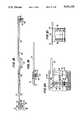
- FIG. 16is an isometric representation of the computer display in the detached, free-standing condition
- FIG. 17is a side elevational view of the detached computer display
- FIG. 18is a front elevational view of the computer display base
- FIG. 19is a side elevational view, partly in section, of the computer display base taken along line 19--19 of FIG. 18;
- FIG. 20is an enlarged side elevational view, partly in section, illustrating the computer display mounting connection to the chassis;
- FIG. 21is a view taken along line 21--21 of FIG. 20;
- FIG. 22is a top plan view of the battery pack
- FIG. 23is a side elevational view of the battery pack
- FIG. 24is a bottom plan view of the computer chassis
- FIG. 25is an enlarged partial elevational view, partly in section, illustrating the battery pack latch mechanism
- FIG. 26is a partial top plan view of the latch mechanism of FIG. 25;
- FIG. 27is an isometric view of the latch mechanism actuator slide
- FIG. 28is a partial rear elevational view of the computer apparatus with its rear end elevated
- FIG. 29is a partial side elevational view of the computer apparatus with its rear end elevated
- FIG. 30is a partial side sectional view of the rear side of the chassis and closure panel
- FIG. 31is a partial plan view taken along line 31--31 of FIG. 30;
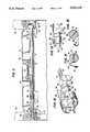
- FIG. 32is a front elevational view of the docking module
- FIG. 33is a rear elevational view of the docking module
- FIG. 34is a plan view of the docking module with parts broken away to illustrate the toggle latching mechanisms
- FIG. 35is an exploded isometric view illustrating the principal component parts of a toggle latching mechanism utilized with the docking module of FIG. 32;
- FIG. 36is a view taken along line 36--36 of FIG. 32 illustrating one form of a docking module connector mounting
- FIG. 37is a view taken along line 37--37 of FIG. 32 illustrating another form of docking module connector mounting.
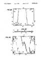
- FIGS. 38 to 41are partial plan views of the docking module and computer chassis illustrating various stages of the mounting procedure.
- FIGS. 1 and 2 of the drawingsthere is shown a computer apparatus 10 particularly adapted for utilization, alternately, as a portable, so-called lap-top computer, or as a desk-top computer.
- the computer organizationcomprises four main sub-assemblies; namely a central processing unit (CPU) 12, a display 14, a battery pack 16 and a docking module 18.
- the display 14is mounted for pivotal movement with respect to the CPU 12 and, as shown in FIG. 2, when closed forms part of the computer enclosure structure.
- each of the sub-assemblies, including the display 14, the battery pack 16 and the docking module 18is detachable from the CPU 12 in order to enhance the versatility of application of the computer apparatus 10.
- CPUCentral Processing Unit
- the CPU 12comprises a metal casing structure forming a chassis or housing 20 containing a plurality of components, many of which are not germane to the present invention, as for example, data processing means, such as one or more microprocessor or microcomputer chips; a small random access memory; and means for electrically connecting the various components of the computer.
- Electric power to the computeris derived from the battery pack 16 during the lap-top mode of operation, while, or operating during the desk-top mode, power can be input from a house source of electric power.
- the chassis 20is formed of generally rectangularly positioned front and rear walls 22 and 24 and left and right side walls, 26 and 28, respectively, that extend between, and interconnect, a bottom wall 30 and a top wall 32.
- the top wall 32has a stepped configuration containing a keyboard 34 in the forward portion thereof and mounting the display 14 at a slightly elevated position in the rearward portion.
- a disc access opening 36is disposed in the right side wall 28 with a depressible disc release actuator 38 conveniently located adjacent thereto.
- the rear side wall 24 of the chassis 20(FIG. 4) is provided with a pivotally mounted single pole power switch 40 located adjacent the left side wall 26. Adjacent the switch 40 and closed by a closure cover 42 is a region 44 in which the connectors for various peripheral equipment are contained.
- Such connectorsinclude various female connectors, 46 through 54, having multiple prongs for connection with mating connectors of individual pieces of peripheral equipment, or with an assemblage of such connectors, such as contained in the docking module 18, discussed in detail hereinafter.
- the bottom surface 34 of the CPU 12may be provided with a plurality of resilient feet 229 to cushion engagement of the chassis 20 with a support surface when the battery pack 16 is removed.
- the display 14 in such apparatusprovides the output of computer graphics to the operator.
- the display 14is of the liquid crystal-type being contained in a display housing 60.
- the display housing 60is connected to the rearward portion of the top wall 32 of the CPU 12 via a base or jamb 62 that is adapted for releasable attachment to the CPU.
- the display housing 60is connected to the base 62 for pivotal movement between a position, shown in FIG. 2 as being essentially horizontal, in which the housing effectively covers and encloses, via a skirt 61, the computer top wall 32 in order to protect the keyboard 34. From the horizontal attitude the housing 60 is pivotable to a maximum angularly extended position for graphics display, shown in FIG.
- Position control meansenable the display housing 60 to be retained in any angular position between the horizontal position and its maximum extended position.
- Releasable latches 64each having an associated actuator 66, are retained in the left and right side walls, 26 and 28, for releasably securing the display housing 60 in its closed position.
- the display housing 60comprises an assembly of oppositely disposed metal panels formed of cast aluminum or magnesium-alloy and including front panel 68 and rear panel 70. Interposed between the panels 68 and 70 in sandwiched relation thereto, are a forwardly positioned liquid crystal display (LCD) plate 72 and an electric luminescent panel 74 therebehind. Surrounding the LCD plate 72 are rectangularly arranged printed circuit boards 76 that form part of the electrical connection between the CPU 12 and the display 14.
- LCDliquid crystal display
- the sub-assembly consisting of the plate 72 and circuit boards 76are resiliently cushioned by generally U-shaped shock mounts 78 disposed substantially at the intersecting corners of the sub-assembly and adapted to be received into seats 80 integrally formed on the interior surface of the front panel 68.
- connection arrangementthat comprises the interengagement of oppositely directed lips 82 and 84 (FIG. 8) that extend along the longitudinal edges of the respective panels that form the upper or free side of the display 14.
- the connection arrangementfurther includes, along each of the remaining three sides of the housing 60, the provision on the oppositely facing, interior surfaces of the front and rear panels 68 and 70 of alternately spaced projections 86 containing longitudinal recesses 88.
- the projections 86 on the rear panel 70are integrally formed along the inturned panel edge 90 to face inwardly therefrom.
- the projections 86 on the front panel 68are formed as part of an integrally formed strip 92 spaced inwardly from the panel edge and upstanding from the interior surface of the panel with the projections 86 being disposed on the outwardly facing side of the strip.
- the projections 86 on the respective panelsare on alternate spacing and organized to be mutually interfitting when the panels are brought together in assembled relation.
- the recesses 88 in the respective projections 86are so arranged as to be axially aligned upon assembly of the panels so as to form an elongated opening for reception of a straight, elongated fastening pin 94.
- the fastening pins 94are of a diameter to be snugly received in the elongated opening formed by the aligned recesses 88.
- the pins 94at their rear ends, are provided with threads 95 that permit them to be attached to a tool (not shown) by which they can be rotated as they are inserted into their associated elongated opening. Rotating the pins in this manner facilitates their insertion and extension along the elongated openings. To further facilitate passage of the pins 94 through these openings their leading ends may be pointed as shown at 97 in FIG. 9.
- a closure plug 96may be installed to cover the threaded end of each pin 94 by resilient engagement with the wall of a counterbore 98 formed in the panels.
- the plugs 96are each sized to substantially fill the respective counterbores 98 and are located at the bottom ends of the negative side edges of the display housing 60 and at one end along the bottom or pivot side of the housing.
- These openings 98are formed by semi-cylindrical segments in the respective panels 68 and 70 and are completed when the panels are brought together upon assembly.
- the closure plugs 96are first removed from the respective openings 98 and the aforementioned tool threadedly attached to the end of the respective fastening pins 94 for their withdrawal from the openings in which they are disposed.
- the panels 68 and 70can be manipulated with respect to each other thereby disengaging the lips 82 and 84 and permitting the panels to be separated.
- the display housing 60is journalled for pivotal movement in the base or jamb 62, the latter being comprised of a metal casting containing integrally formed journals 100 and 102 (FIG. 11) disposed at opposite ends thereof and a cast metal cover 63 (not shown in FIG. 11) that closes the casting.
- a pivot shaft 104that is fixedly secured to the display housing 60 and that extends from one lateral end thereof, serves as the pivot axle.
- This shaft 104provides the supplemental function of guidingly attaching a flexible circuit strip 106 that defines the electrical connection between the CPU 12 and the display 14, the details of which attachment are described hereinafter.
- This position control apparatus 109comprises an elongated cylindrical rod 110 formed of spring steel extending end-to-end between the lateral sides of the display assembly and received in a receptacle 112 formed in the display housing panel 68 adjacent the fastening pin 94 that secures the bottom edges of the housing panels 68 and 70.
- the rod 110contains a substantially perpendicular offset portion 114 that is received in a receptacle 116 formed by spaced projections cast along the side portion of the front panel 68.
- the rod 110contains a substantially perpendicular offset portion 120 that, as shown in FIG. 6, is angularly offset about 80° with respect to the offset portion 114.
- the offset portion 120is adapted to be received in a receptacle 122 (FIG. 11) formed in the base 62 by case projections.
- the respective offset end portions 114 and 120 of the rod 110serve to anchor opposite ends of the rod to the display housing 60 and base 62, respectively, so that the rod incurs torsional stressing during pivoting of the display housing with respect to the base.
- the rod 110is designed to contain a torsional prestress selected such that it is essentially zero psi when the display housing 60 is disposed about 10° beyond its vertical position with respect to the upper surface 32 of the CPU 12.
- a torsional prestressselected such that it is essentially zero psi when the display housing 60 is disposed about 10° beyond its vertical position with respect to the upper surface 32 of the CPU 12.
- the stress profileis such that, when the latches 64 are actuated to release the housing 60 from the sides of the chassis 20, the housing will automatically spring to a slightly raised position above the upper surface of the chassis. This facilitates its being manually gripped for further manipulation.
- the rod 110telescopically receives the pivot sleeve 108 about the offset portion 120.
- the pivot sleeve 108when assembled on the rod 110, extends beyond the end of the display panels, 68 and 70, and is received in the journal 122 provided in the casting forming the base 62, wherein it is anchored in place by the assembly of the cover 63 and whereby it forms the other display pivot axle.
- the friction retention force generated by the band brake 130is effective to retain the display 60 in any angular position between its initial, slightly raised, unlatched position and its maximum full open position, thereby to enable adjustment of the display in any angular position between these positions.
- the displayis held in its various angular positions principally by the friction force developed by the cylindrical portion 132 of the band brake 130 on the pivot sleeve 108.
- the torsion rod 110besides being useful in reducing the gravitational effects of the display 14 and thereby the amount of effort required to move it, interacts with the band brake 130 to reduce significantly the amount of friction force necessary to be generated by the band brake for retaining and display. Therefore, the size of the respective elements required to retain the display is minimized such that the display housing structure required for their containment is small.
- the electrical interconnection between the CPU 12 and the display 14is effected by a flat, flexible plastic circuit strip 106, of generally known construction, in which a plurality of electrical conductors are embedded.
- the circuit strip 106has one terminal end electrically connected to a multi-pronged terminal plug 138 centrally disposed in the base 62 of the display 14.
- the plug 138is adapted for connection in a mating plug (not shown) that is accessible through opening 140 in the upper wall 32 of the CPU 12 which wall is closed by depressible, spring-biased closure covers 142.
- the strip 106is adapted for connection to one or more of the printed circuit boards 76.
- the strip 106contains a pair of parallel leg portions 142 and 144 and a nexus portion 146.
- One leg portion 144extends to the nexus portion 146 from the terminal plug 138 and is fixedly secured in a track 148 formed in the base casting upon assembly of the base 62.
- the other leg portion 142extends to the nexus portion 146 of the strip from that terminal end which is connected to the circuit board 76.
- the leg portion 142is fixedly secured between the panels 68 and 70 that form the display housing 60 and is adapted to undergo movement with the housing when it is pivoted about the base 62.
- a flex bushing 150that defines the pivot shaft 104.
- the flex bushing 150has a body having a generally cylindrical section 152 and a generally rectangularly sided anchor section 154 separated by an enlarged diameter flange 156.
- the busing 150is retained between the display housing panels 68 and 70 with the anchor section 154 being seated in a cast receptacle in the panels so that the bushing remains stationary with respect to the display housing 60 for angular movement therewith.
- the cylindrical section 152 of the bushing bodyextends from an opening in the housing and is mounted for pivotal movement in the journal 100 formed in the casting defining the display base 62. This opening is effectively closed by the close proximity of the flange 156 on the bushing body to the opening. It will be appreciated that the bushing body thus forms the other pivot axle for the display 14.
- the body of bushing 150extends in a direction transversely of the nexus portion 146 of the circuit strip 136 in order to grasp the strip 136 substantially along the longitudinal axis of the leg portion 142.
- Grasping of the strip 106 in this manneris effected by the fact that the bushing body contains a longitudinal slot 157 produced by the body's being fabricated in half sections that are joined by a flexible connector strip 158 that permits the sections to be folded upon each other.
- the attached portion of the strip 106is retained on the bushing 150 by being sandwiched between the respective half sections.
- the cylindrical section 152 of the bodyis formed as a recess that is shouldered at each end, as shown at 160, within which recess the exposed part of the nexus portion 146 of the circuit strip 106 is wound as the bushing rotates in journal 100 upon pivotal movement of the display 14.
- FIGS. 14 and 15The action of the strip 106 formed by the nexus portion 146 is best illustrated in FIGS. 14 and 15, wherein it is evident that sufficient slack is made available in the strip to create an undulation or wave of sufficient longitudinal extent to permit the bushing body 150 to undergo about 135° of rotation in the journal 100 without applying undue tension to the strip material.
- the material forming the nexus portion 146 of the circuit strip 106winds upon the reduced diameter portion 152 of the bushing and is confined thereto by the shoulders 160 formed at the respective ends of the recess.
- the strip materialis caused to undergo controlled movement as the display 14 moves with respect to the base 62, thereby preventing the creation of snarls in the strip that might create damage or breakage thereof or might, otherwise, cause a system malfunction.
- the display 14, including the housing 60 and base 62can be completely detached from the CPU chassis 20 and made to be free standing.
- This desirable featureis obtained by the provision, on the underside of the base 62 adjacent opposite ends thereof, of looking cams 162 fixedly attached to operating levers 164.
- the organizationis such that, when the display 14 is detached from the CPU 12, the operating levers 164 of the locking cams 162 advantageously serve as support legs for the free standing assembly and the locking cams 162 serve as support feet to raise the front end of the assembly with respect to its back end. In this way a greater degree of inclination can be imparted to the display housing 60, to both enhance viewing of the projected graphics and to improve stability of the free standing structure by moving its center of gravity rearwardly.
- FIGS. 11 and 18depict a plan view and a rear view, respectively, of the base 62 on which the locking cams 162 are mounted.
- the cams 162comprise bodies having parallel, somewhat elongated, linear sides 166 and rounded, generally circular ends 168.
- the cam bodiesare integrally formed on one end of the respective levers 164, with the assembly being connected for pivotal movement via a spring-biased fastener 163 to the casting forming the base 62.
- the levers 164are in their extended positions, and normal to the longitudinal axis of the base 62, the sides 166 of the cams 162 are caused to be aligned with the base axis.
- the levers 164are rotatable 90° to be received in openings 169 formed in the base 62, whereupon the sides 166 of the cams 162 are made to be disposed perpendicular to the base axis, thus to effect a locking mode, as hereinafter explained.
- the top wall 32 of the chassis 20 adjacent its rear endcontains three openings, indicated as the centrally disposed plug opening 140 and openings 172 spaced on opposite sides of the central opening 140.
- the central opening 140provides access to a female terminal connector (not shown) for the terminal plug 138 located on the underside of the housing base 62.
- the plug 138attaches directly to the mating female connector in the chassis 20.
- an elongated electrical connector indicated as 174 in FIG. 16is made to connect between the respective aforementioned terminal connectors.
- the electrical connector 174may be arranged to carry a body 175 forming a foot for stabilizing the display 14 when it is separated from the computer 12.
- Each of the openings 172is, as shown, rectangular in shape and is closed by a flat closure plate 176 that is mounted in cantilever-fashion via a base 178 having openings that move along a pair of depending, sleeved posts 180 and that is biased upwardly by means of springs 182 positioned between the head of the posts 180 in each pair and the base that moves therealong.
- the levers 164are moved to their extended position perpendicular to the base axis. This movement positions the locking cams 162 with their sides 166 parallel to the base axis and in a position to be received by the respective openings 172 in the upper surface 32 of the chassis 20.
- the base 62is caused to be moved downwardly toward the chassis top wall 32 such that the cams 162 simultaneously enter the openings 172 and the plug 138 enters the opening 140 pivoting the closures 142 open for connection of the plug 138 to the mating female plug.
- the respective levers 164are thereafter rotated to be moved into the elongated openings 169 formed in the display base 62.
- This actioncauses the locking cams 162 to rotate 90°, whereupon the elongated sides 166 of the cams are made to extend transversely beyond the short sides of the openings 172 thus to prevent withdrawal of the cams from the openings.
- the top surfaces 185 of the camsupon rotation, are urged into locking engagement with the undersurface of the chassis top wall 32 by means of the curvature of the surface 185, thereby to securely attach the display 14 to the CPU 12.
- the computer apparatus 10is equipped with a battery pack 16 of particular design that is releasable from attachment to the CPU 12 for recharging or for other purposes.
- the battery pack 16comprises a plurality of rechargeable cells (not shown) that are housed within a container 186 of reduced vertical dimension having generally rectangularly shaped, parallel upper and lower walls 188 and 190 that are interconnected by rectangularly arranged upstanding front, rear and oppositely spaced side walls 192, 194, 196 and 198, respectively.
- a contact assembly 199 formed of a plurality of resilient contact elementsis here shown as being located adjacent the corner formed by the intersection of the rear wall 194 and side wall 196.
- the contact elements 199a of the assembly 199are arranged to resiliently engage contact elements (199b) (FIG. 24) disposed on the chassis bottom wall 34 in overlying relation to the contact assembly on the battery pack 16 when in its latched, operative position.
- the securing members 200are formed of generally flat bodies each having its longitudinal axis extending parallel to the adjacent battery side wall.
- the members 200are adapted to be received in slots 201 provided in the bottom wall of the CPU chassis 20.
- the slots 201have a shape corresponding to the sectional shape of the members 200, but are slightly elongated in the longitudinal direction and have their hook-forming openings 202 facing in the direction of the battery rear wall 194.
- the particular shape of the securing members 200dictates that, upon both installation and removal of the battery pack 16 to and from the bottom wall 34 of the chassis 20, there will be relative sliding contact between the contact elements 199a on the battery pack body 186 and the mating contacts 199b on the chassis bottom wall 34 so that damaging oxide accumulation on the respective contacts is prevented.
- a releasable latching mechanismis employed to couple the battery pack 16 to the chassis 20 of CPU 12.
- the latching mechanism 203comprises a depressible detent 204 that is adapted to be received in a mating slot 205 in the bottom wall 34 of the chassis.
- the detent 204is integrally formed on an operator arm 206 having a composite shape that enables it to be retained within the battery pack container structure for pivotal movement; to be spring biased; and to be cam actuated within a restricted space.
- the operator arm 206is formed of a sheet metal body that is housed within a cast portion 208 of the battery pack frame structure, from which the detent 204 is vertically extensible and retractable by pivotal movement of the operator arm.
- the operator arm 206is formed at one end with a substantially circularly formed pivot portion 210 that rests in a pivot seat 212 of complementary shape in the cast portion 208.
- the arm 206contains a longitudinal extension 214, the bottom surface of which engages a spring 216 that is contained within a spring seat 218 in the cast portion 208 and that normally biases the engaged end of the arm upwardly.
- the arm 206possesses a cam surface 220 that is inclined upwardly in the direction of the detent 204 and adapted for reception of a movable boss 222 formed on an actuator slide 224.
- the actuator slide 224contains two laterally spaced body portions 226 and 228 joined by connector 227.
- the spacing between the body portions 226 and 228 and the position of the connector 227 therebetweenis such as to permit the actuator slide 224 to be retained for longitudinal sliding movement on the battery pack frame structure.
- the body portion 226 containing the boss 222also contains a post 232 to which one end of a spring 234 is attached. At its other end the spring 234 is attached to a post 236 on the cast portion 208 such that the actuator slide 224 is normally biased to its retracted position with the boss 222 positioned in the deepest part of the recess forming the cam surface 220 so that the detent 204 is normally located in its vertically extended position.
- the other actuator body portion 228is disposed exteriorly of the battery pack container and may be provided with a knurled, or otherwise roughened surface, to facilitate its manual operation.
- the actuator 224is manually moved to the right as it appears in FIGS. 22, 25 and 26 so as to pivotally depress the operator arm 206 and withdraw the detent 204 from the mating slot 205 in the CPU chassis. Withdrawal of the detent 204 from its mating slot 205 permits the battery pack 16, and thus the securing members 200, to be moved rearwardly for release of the members from the slots 201 in which they extend.
- This longitudinal movement of the battery pack with respect to the chassis 20effects a sliding action of the contact elements 199a on the battery pack with the contact elements 199b on the chassis, thereby advantageously wiping any accumulated metal oxide from the surface of the respective contacts.
- the detent 204will, when the facing surfaces of the chassis and the battery pack bear against each other, be forced downwardly depressing the operator arm 206 against the spring 216.
- the detent 204being upwardly biased by spring 216, will automatically enter the mating slot 205 to secure the battery pack to the chassis.
- the facing surface 188 of the body 186 of the battery pack 16contains recesses 230 formed and located to provide clearance for the respective feet 229 on the bottom surface 34 of computer chassis 20.
- the chassis 20 of CPU 12mounts the various aforementioned eleCtrical connectors including principally the expansion bus connector 46, video connector 48, a connector 25 for a printer or the like, modem connections 52, and a keyboard connection 54.
- Other connectionssuch as that indicated as 53 for a mouse, and connector ports 55 to accommodate connection of other compatible apparatus can also be provided.
- the computer power switch 40Also disposed on the rear wall 24 is the computer power switch 40, the actuation of which activates the computer, either by power from the battery pack 16 or from an external power source.
- the region 44 of the rear wall that contains the respective electrical connector members 46 through 55is made to be slightly recessed from the lateral end portions of the rear wall. Closing the recessed region 44 is a closure panel 42 formed by a plate 246, the external surface of which is substantially coplanar with the adjacent portions of the rear wall.
- the plate 246is mounted via pivot pins 248 disposed at opposite ends of the panel lower portion and journalled in openings formed in the facing sides 250 of the recess that forms region 44.
- the plate 246is angularly displaceable through a range of movement of about 180°, from the vertically upright position shown in FIGS. 4 and 30, in which it serves to enclose and cover the region 44, to the vertically downturned position of FIGS. 28 and 29 in which the plate 246 serves as a support standard for raising the rear of the chassis 20, thereby to permit the CPU 12 to be supported in an inclined attitude, if desired.
- the plate 246, as shown in FIG. 5,is also adapted to assume a third position, intermediate the other two positions, in which it is disposed substantially parallel to the bottom wall 32 of the CPU chassis 20 In this position the plate is effective to permit access to the various connectors in the region 44 of the chassis rear wall 24 with the chassis 20 oriented in an essentially horizontal position.
- Mechanismis provided to effectively secure the plate 246 in each of its three operative positions.
- This mechanismcomprises, at each opposite end of the plate 246 adjacent the pivot pins 248, a camming surface, indicated generally as 252, having four rectangularly disposed sides, three of which, indicated as sides 254, 256 and 258, are cam surfaces engageable by a spring biased follower 260.
- Each follower 260comprises a pressing foot 262 that is separated by an enlarged shoulder 264 from a guide post 266.
- the pressing foot 262 on each followeris adapted to extend through an opening 268 in the chassis rear wall 24 in order to access the surface 252.
- the follower 260is biased outwardly by a spring 270 that surrounds the guide post 266 and extends between the shoulder 264 and a spring retainer 272 integrally formed on, and upstanding from, the interior surface of the chassis bottom wall 30.
- the movement of the pressing foot 262is guided by a pair of retainers 272 that are also upstanding from the interior surface of chassis wall 30.
- the side 254 of the camming surface 252 of the cover 427is engaged by the pressing foot 262 of the follower 260 with the closure plate 246 in its vertically upright position.
- the spring force imposed on the follower 260 by spring 270is of the order of magnitude of about 50 pounds to, thus, secure the plate 246 in the selected position.
- the follower 260is depressed against the spring 270, to be returned to pressing engagement with the surfaces 256 and 258 when the plate has been moved to dispose one or the other of the surfaces to a disposition normal to the axis of the pressing foot.
- the camming surface 252is advantageously arranged to permit relatively easy movement of the plate 246 between its vertically upright position and its intermediate position parallel to the chassis bottom wall 30. This relative ease of movement is effected by a depression 274 at the intersection of the sides 254 and 256. Such depression may be formed by either a curved surface extending between the two sides or, as shown, by a linear diagonal nexus surface that intersects the two sides at about 45°.
- the intersection between the sides 256 and 258 of camming surface 252is maintained essentially at right angles. This is to increase the force required to depress the follower 260 and, concomitantly, the force necessary to move the plate 246 between its intermediate and its standard-forming position. More importantly, this device increases the retrograde force required to move the cover plate 246 between its standard-forming, downturned position back to its intermediate, horizontal position, so as to reduce the danger of collapse of the support for the rear end of the chassis 20 when it is in its raised position.
- the configuration of the camming surface 252in cooperation with the follower 260, is such as will permit relative ease of movement of the closure plate 246 from its position closing the recessed region 44 of the chassis rear wall 24 to its open position.
- the configuration of the camming surface 252is also such as will render it difficult for the plate 246 to be accidently dislodged from its vertically downturned position, where a sudden collapse of the support standard could damage the computer apparatus.
- the docking module 18whose function it is to effect connection between the computer chassis 20 and various pieces of ancillary equipment without the need for individual cable connections, thereby to facilitate conversion of the computer between its lap-top mode of operation and its desk-top operating mode.
- the docking module 18comprises a metallic casing 283 formed by the assembly of an upper shell 284, a lower shell 286, a front bezel 288 and a rear bezel 290.
- the opposite side surfaces 292 and 294 of the docking module 18are formed by the cooperation between perpendicularly offset wall portions, such as those indicated as 286a and 286b, that extend from the upper and lower shells 284 and 286, respectively.
- toggle latch mechanisms 296,mounted on the respective side surfaces 292 and 294 and separated from the interior region of the docking module by an arcuately formed shielding partition 295 are toggle latch mechanisms 296, each consisting principally of a latch hook 300, and a toggle lever 302, and each of which is formed of a rigid material. Since the sole structural difference existing between the respective toggle latch mechanisms 296 is the opposite facing disposition of the gripping projections 304 on the latch hooks 300, only one such toggle latch mechanism will be described in detail.
- the toggle lever 302is a substantially U-shaped member having a body 306 containing oppositely spaced arms 308 and 310.
- the arms 308 and 310 adjacent their leading endscontain axially aligned pivot holes 312 adapted for reception on pins 314 which are integrally formed on the upper and lower shells 284 and 286, respectively, in oppositely facing relation to one another.
- the space between the arms 308 and 310receives the latch hook 300 that is connected via a pivot pin 316 to the toggle lever 320 and that has formed thereon the inturned hook-like gripping projection 304.
- Each toggle latch elementis spring biased by a compound leaf spring assembly 318 that is fixedly attached at one end in a recess 320 integrally formed in standards 322 cast in the upper and lower shells 284 and 286, respectively.
- Each spring assembly 318comprises a central spring element 324 whose free end is angularly offset and adapted to engage a cam element 326 formed on the rear end 328 of the latch hook 300.
- the spring assemblyis operable to bias the rear end 328 of the latch hook 300 outwardly and, thus, the leading end that contains the projection 304, inwardly.
- Straddling the central spring element 324is a lever spring 330 adapted at its free end to alternately engage angularly disposed cam surfaces 332 and 334 formed on a cam nose 336 that is integrally formed on the toggle lever body 306 extending between the arms 308 and 310.
- the disposition of the cam surfaces 332 and 334 on the cam nose 336is such as, in cooperation with the lever spring 330, to biasingly retain the lever 302 alternatively in its angularly outer or released position and in its latching or angularly inner position.
- the toggle mechanisms 296 and 298are arranged to secure the docking module 380 to the computer chassis 20 by the cooperation of the projections 304 on the latch hooks 300 with recessed depressions 340 (FIG. 29) formed on the left and right side walls 26 and 28 of the computer chassis 20 adjacent the rear ends thereof and formed to receive and grip the projections 304 so as to draw the docking module 18 and the computer chassis 20 toward each other and to secure them together.
- the location of the respective depressions 340 vis-a-vis the toggle mechanisms 296 and 298is such that the mechanisms operate to emit an audible signal when the projections 304 formed on the leading ends of the respective latch hooks 300 enter their respective associated depressions 340 to indicate that all of the complementary connectors on the docking module 18 and computer chassis 20 are properly aligned so as to permit actuation of the toggle levers 302 to draw the respective apparatus together and thereby further extend the pins on the male connectors into the receptacles on the female connectors without danger of damaging any of the connectors.
- the biasing force of the central spring elements 324 on the latch hooks 300accordingly serve, not only to bias the projections 304 inwardly into the inserted relation with the depressions 340 but, do so with such force that an audible noise results which serves as the aforementioned signal.
- the face of the front bezel 288mounts connectors that complement the connectors 46 through 55 mounted on the rear wall of the chassis 20.
- those connectors mounted on the front bezel 288 and indicated by the same numeral but with a prime superscript as the reference numeral that designates the connector on the CPU 12 with which it connectsare adapted to float to a limited degree by the provision of slightly oversized holes in which the respective connectors are mounted, thereby to impart a self-alignment feature to the concerned connectors.
- FIGS. 36 and 37depict examples of the two typical forms of connector mountings existing in the docking module.
- FIG. 36is shown a multi-pin connector similar to the connector 55', adapted for reception in a mounting hole 344 of slightly oversized, conforming shape.
- the connector 55'comprises a frame 346 adapted for reception of screws 347 at the opposite lateral ends thereof.
- the mounting hole 344is provided with oppositely spaced, lateral recesses 348 into which is inserted a flexible grommet 350 configured to fit snugly in the recess in concentric, surrounding relation to the neck of a tubular nut 352.
- the grommets 350 and nuts 352are inserted into the recesses 348 in alignment with openings in a flange 354 for reception of screws 347.
- FIG. 37depicts another form of electrical connector 358, typically formed of plastic material, whose body 360 is provided at one end with an outwardly extending flange 362 adapted to engage one side of the inturned flange 364 that extends about the periphery of the mounting hole 366 in the front bezel 288.
- a plurality of flexible fingers 368Spaced rearwardly from, and extending toward, the flange 362 are a plurality of flexible fingers 368 whose gripping faces oppose the flange 362 and in cooperation therewith are adapted to engage the opposite side of the flange 364.
- Appropriate sizing of the hole 366 vis-a-vis the body 360provides the connector 358 with a limited degree of float, both horizontally and vertically, on the docking module 18, thus to impart the connector with a self-alignment capability.
- Assisting in the alignment of the electrical connectors on the docking module 18 with those on the chassis 20are a pair of alignment pins 370 that are flexibly secured to the front bezel 288 by a spring or other flexible connection.
- the pins 370are desirably disposed on laterally oblique spacing on the front bezel and extend forwardly from the surface thereof to be received in mating holes 372 formed in the chassis rear wall 24.
- a pusher linkage 374comprising an actuating lever 376 accessible from the rear face of the docking module and an operating lever 378 that protrudes through an opening in the front bezel 288 to engage the switch 40 on the CPU chassis 20.
- the levers 376 and 378are each mounted for pivotal movement on pivot pins 380 and 382 upstanding from the front and rear edges, respectively, of the lower shell 286.
- a link 384extends between, and interconnects, corresponding arms on the respective levers such that a pivoted action imposed on the actuating lever 376 will be directly imparted to the operating lever 378 and, concomitantly, to the power switch 40 on the computer chassis.
- the operation of the described docking module 18is as follows. In a typical application the docking module 18 will be disposed on a support surface at a location at which desk-top operation of the computer apparatus is intended.
- To each of these connectors on the rear bezel 290are connected, via appropriate cabling the ancillary equipment intended for use with the computer 10. Such equipment may include a video apparatus, a printer, a modem, etc. It Will be appreciated that cabling, once attached to the docking module 18, is intended to remain essentially permanently attached regardless of whether the computer 10 is attached to the docking module, or not.
- the electrical connectors mounted on the front bezel 288complement, and are electrically connected to those on the rear bezel 290. They also complement those on the computer chassis rear wall 24. Consequently, the mating connection of the connectors on the computer chassis 20 to those on the docking module 18 will effectively connect the computer 10 to all apparatus from which cabling is extended and attached to the connectors on the docking module rear bezel 290.
- the effect of thisis to greatly facilitate conversion of the computer from its lap-top or portable, operating mode to a desk-top mode, or viceversa, in that the need to independently and individually make or break connections to the various equipment attached to the computer is eliminated. Instead, only a single connection need be made of the computer 10 to the docking module 18 that simultaneously effects all of the connections to be made.
- the front of the docking module and the rear of the chassisare placed in a face-to-face relation and the alignment pins 370 on the docking module are caused to enter the mating holes 372 in the computer chassis 20 (FIG. 39).
- the computer chassis 20 and the docking module 18are, thereafter, moved closer together with the projections 304 on the latch hooks 300 of the toggle latch mechanisms in sliding contact with the wall surfaces rearwardly of the depressions 340.
- the interstitial space between the docking module 18 and the computer chassis 20is such that the projections 304 on the latch hooks 300 are caused to enter the depressions 340 in the chassis side walls 26 and 28.
- the latch hooks 300are spring-biased by the central spring elements 324, the projections 304 are caused to enter the depressions 340, as shown in FIG.
- a manual five pound actuating force on the levers 302produces about an eighty pound attachment force between the hook projections 304 and the engaged edges of the depressions 340 on the chassis.
- the spring force between the lever springs 330 on the surface 334 on the respective cam noses 336serves to retain the levers in place. Thereafter, utilization of the computer can commence upon actuation of the power switch 40 via actuation of the pusher linkage 374.
- the levers 302are released from their locked position of FIG. 41, whereupon, in returning to their open position under the influence of the spring 330, the reactive force generated between the tip 303 of the hook 300 and the adjacent edge of the depression 340 in the chassis 20 effects a slight retrograde movement of the docking module from the chassis.
- the lever 302is moved slightly forwardly from its open position whereupon, by action of the cam surface 305 on the front bezel 288 and the follower 307 on the hook 300, the latter is urged laterally outwardly from the depression so as to enable final separation of the docking module from the computer.
Landscapes
- Engineering & Computer Science (AREA)
- Theoretical Computer Science (AREA)
- Computer Hardware Design (AREA)
- Human Computer Interaction (AREA)
- Physics & Mathematics (AREA)
- General Engineering & Computer Science (AREA)
- General Physics & Mathematics (AREA)
- Casings For Electric Apparatus (AREA)
- Details Of Connecting Devices For Male And Female Coupling (AREA)
Abstract
Description
Claims (11)
Priority Applications (5)
| Application Number | Priority Date | Filing Date | Title |
|---|---|---|---|
| US07/319,200US5030128A (en) | 1989-03-06 | 1989-03-06 | Docking module |
| PCT/US1990/000965WO1990011628A2 (en) | 1989-03-06 | 1990-03-02 | Docking module |
| AU51966/90AAU5196690A (en) | 1989-03-06 | 1990-03-02 | Docking module |
| CA002011426ACA2011426A1 (en) | 1989-03-06 | 1990-03-05 | Docking module |
| CN90101194.0ACN1046056A (en) | 1989-03-06 | 1990-03-06 | Connecting element |
Applications Claiming Priority (1)
| Application Number | Priority Date | Filing Date | Title |
|---|---|---|---|
| US07/319,200US5030128A (en) | 1989-03-06 | 1989-03-06 | Docking module |
Publications (1)
| Publication Number | Publication Date |
|---|---|
| US5030128Atrue US5030128A (en) | 1991-07-09 |
Family
ID=23241268
Family Applications (1)
| Application Number | Title | Priority Date | Filing Date |
|---|---|---|---|
| US07/319,200Expired - LifetimeUS5030128A (en) | 1989-03-06 | 1989-03-06 | Docking module |
Country Status (5)
| Country | Link |
|---|---|
| US (1) | US5030128A (en) |
| CN (1) | CN1046056A (en) |
| AU (1) | AU5196690A (en) |
| CA (1) | CA2011426A1 (en) |
| WO (1) | WO1990011628A2 (en) |
Cited By (135)
| Publication number | Priority date | Publication date | Assignee | Title |
|---|---|---|---|---|
| US5177665A (en)* | 1991-10-01 | 1993-01-05 | Progressive Insurance Corp. | Housing and vehicular support for portable computer |
| US5187645A (en)* | 1991-06-07 | 1993-02-16 | Ergo Computing, Inc. | Portable computer with docking connector for peripheral devices |
| US5196991A (en)* | 1991-09-13 | 1993-03-23 | Hsieh La Fai | Portable computer having pivotable detachable cover with display |
| US5206790A (en)* | 1991-07-11 | 1993-04-27 | Zeos International, Ltd. | Pivot and swivel mechanism for lap top display |
| US5265238A (en)* | 1991-01-25 | 1993-11-23 | International Business Machines Corporation | Automatic device configuration for dockable portable computers |
| WO1994000808A1 (en)* | 1992-06-19 | 1994-01-06 | Toshiba (Australia) Pty. Limited | Computer interface |
| US5290178A (en)* | 1992-03-10 | 1994-03-01 | Ma Hsi K | Docking station apparatus for portable computer |
| US5301132A (en)* | 1991-07-23 | 1994-04-05 | Sony Corporation | Assembly structure for information inputting apparatus |
| US5313596A (en)* | 1993-01-05 | 1994-05-17 | Dell Usa Lp | Motorized portable computer/expansion chassis docking system |
| US5327322A (en)* | 1993-03-30 | 1994-07-05 | Ma Hsi Kuang | Built-up pen base computer |
| US5394552A (en)* | 1990-11-19 | 1995-02-28 | Seiko Epson Corp. | Docking system for enhancing computer functionality |
| US5402166A (en)* | 1991-11-12 | 1995-03-28 | Rank Cintel Limited | Method and apparatus for compensating for film registration weave in film scanning systems |
| US5411416A (en)* | 1994-07-29 | 1995-05-02 | The Whitaker Corporation | Docking connector unit |
| US5443390A (en)* | 1993-07-14 | 1995-08-22 | International Business Machines, Corp. | Computer audio joystick and MIDI breakout box |
| US5460547A (en)* | 1992-04-03 | 1995-10-24 | Zenith Data Systems Corporation | Port replicator |
| US5463742A (en)* | 1993-03-05 | 1995-10-31 | Hitachi Computer Products (America), Inc. | Personal processor module and docking station for use therewith |
| US5472351A (en)* | 1993-10-06 | 1995-12-05 | U.S. Robotics, Inc. | Personal computer modem card interface construction |
| US5475626A (en)* | 1992-03-12 | 1995-12-12 | Ing. C. Olivetti & C., S.P.A. | Portable computer with a simple power supply control of chargeable and non-rechargeable battery packs |
| US5477123A (en)* | 1994-12-12 | 1995-12-19 | Technoggin, Inc. | Connection multiple batteries to battery powered devices |
| US5488572A (en)* | 1994-05-04 | 1996-01-30 | Compaq Computer Corp. | Portable computer system for docking to an expansion base unit |
| US5491609A (en)* | 1994-02-28 | 1996-02-13 | Telepad | Portable electronic platform system |
| US5497245A (en)* | 1992-07-21 | 1996-03-05 | Ricoh Company, Ltd. | Facsimile machine including a power source adaptor used therein |
| US5497339A (en)* | 1993-11-15 | 1996-03-05 | Ete, Inc. | Portable apparatus for providing multiple integrated communication media |
| US5504649A (en)* | 1991-09-06 | 1996-04-02 | Kabushiki Kaisha Toshiba | Electronic apparatus system including expansion unit which has an expansion device for expanding the function of an electronic apparatus and which is connectable to the electronic apparatus by means of a card connector |
| US5504648A (en)* | 1991-09-06 | 1996-04-02 | Kabushiki Kaisha Toshiba | Electronic apparatus and electronic system with expanding apparatus having interlock, ejector, grounding, and lock mechanisms, for expanding function of electronic apparatus |
| US5507661A (en)* | 1991-07-19 | 1996-04-16 | Kabushiki Kaisha Toshiba | Electronic system with expanding apparatus for expanding function of electronic apparatus |
| US5531611A (en)* | 1994-05-04 | 1996-07-02 | Thomas & Betts Corporation | Connector module for local area network |
| US5544010A (en)* | 1990-07-25 | 1996-08-06 | Norand Corporation | Portable electronic device docking system |
| US5555491A (en)* | 1995-02-14 | 1996-09-10 | Toshiba America Information Systems, Inc. | Compact docking station for portable computer |
| US5561589A (en)* | 1990-10-15 | 1996-10-01 | Compaq Computer Corporation | Expansion base and system for portable computers |
| US5568359A (en)* | 1995-05-24 | 1996-10-22 | Dell Usa, L.P. | Portable computer desktop docking system |
| US5598537A (en)* | 1994-03-25 | 1997-01-28 | Advanced Micro Devices, Inc. | Apparatus and method for driving a bus to a docking safe state in a dockable computer system including a docking station and a portable computer |
| US5598539A (en)* | 1994-03-25 | 1997-01-28 | Advanced Micro Devices, Inc. | Apparatus and method for achieving hot docking capabilities for a dockable computer system |
| US5625829A (en)* | 1994-03-25 | 1997-04-29 | Advanced Micro Devices, Inc. | Dockable computer system capable of symmetric multi-processing operations |
| US5632020A (en)* | 1994-03-25 | 1997-05-20 | Advanced Micro Devices, Inc. | System for docking a portable computer to a host computer without suspending processor operation by a docking agent driving the bus inactive during docking |
| USD381956S (en)* | 1995-06-28 | 1997-08-05 | Motorola, Inc. | Computer back panel portion |
| USD381955S (en)* | 1995-06-28 | 1997-08-05 | Motorola, Inc. | Computer back panel portion |
| US5668977A (en)* | 1994-03-25 | 1997-09-16 | Advanced Micro Devices, Inc. | Dockable computer system capable of electric and electromagnetic communication |
| US5675524A (en)* | 1993-11-15 | 1997-10-07 | Ete Inc. | Portable apparatus for providing multiple integrated communication media |
| WO1997037293A1 (en)* | 1996-04-02 | 1997-10-09 | Fieldworks, Inc. | Modular field computer workstation |
| US5676567A (en)* | 1994-12-06 | 1997-10-14 | Dell Usa, L.P. | Internal/external modular interface |
| US5689400A (en)* | 1994-05-31 | 1997-11-18 | Kabushiki Kaisha Toshiba | Portable electronic apparatus including space-saving component mounting features |
| US5738537A (en)* | 1995-04-28 | 1998-04-14 | Kabushiki Kaisha Toshiba | External extension apparatus for extending the function of a portable electronic apparatus |
| US5745341A (en)* | 1996-12-31 | 1998-04-28 | Compaq Computer Corporation | Inclined docking base for a portable computer with a slidable monitor support member |
| US5751545A (en)* | 1996-01-17 | 1998-05-12 | Samsung Electronics Co., Ltd. | Desktop personal computer with an easy assembly structure |
| US5761322A (en)* | 1996-12-31 | 1998-06-02 | Compaq Computer Corporation | Portable computer speaker enclosure |
| US5785533A (en)* | 1993-11-15 | 1998-07-28 | Siemens Nixdorf Informationssysteme Aktiengesellschaft | Termination panel for control unit |
| US5796579A (en)* | 1994-05-31 | 1998-08-18 | Kabushiki Kaisha Toshiba | Portable electronic apparatus having expansion connector covered by pivotally mounted upper and lower covers having laterally extending guide portions |
| US5796580A (en)* | 1993-04-13 | 1998-08-18 | Hitachi, Ltd. | Air-cooled information processing apparatus having cooling air fan, sub-fan, and plural separated cooling air flow channels |
| US5807140A (en)* | 1996-10-01 | 1998-09-15 | Metrovideo, Inc. | Signal coupler with a common ground plane |
| US5818182A (en)* | 1993-08-13 | 1998-10-06 | Apple Computer, Inc. | Removable media ejection system |
| US5826042A (en)* | 1996-08-02 | 1998-10-20 | Compaq Computer Corporation | Portable computer docking station with module connection replicator |
| US5828905A (en)* | 1995-11-13 | 1998-10-27 | Mitsubishi Chemical America, Inc. | Adapter and method of connecting devices associated with at least three different protocols |
| US5838539A (en)* | 1995-11-08 | 1998-11-17 | Electronics Accessory Specialists International | Docking module for portable computers |
| US5837942A (en)* | 1995-10-04 | 1998-11-17 | Becker; Paul R. | Computer CPU plug protector and cover |
| US5841630A (en)* | 1992-07-17 | 1998-11-24 | Kabushiki Kaisha Toshiba | Compact electronic apparatus having battery pack detachably retained by four engaging portions and latch member |
| US5867406A (en)* | 1994-06-16 | 1999-02-02 | International Business Machines Corp. | Docking device for a portable computer and a method for docking a portable computer to the docking device |
| US5875094A (en)* | 1996-08-02 | 1999-02-23 | Compaq Computer Corporation | Portable computer docking station with adjustable insertion angle |
| US5876238A (en)* | 1997-06-17 | 1999-03-02 | International Business Machines Corporation | Device and method for securing integrity of a blind autodock electrical connection |
| US5883820A (en)* | 1994-01-13 | 1999-03-16 | Citizen Watch Co., Ltd. | Computer system |
| US5923757A (en)* | 1994-08-25 | 1999-07-13 | International Business Machines Corporation | Docking method for establishing secure wireless connection between computer devices using a docket port |
| US5929606A (en)* | 1997-08-29 | 1999-07-27 | Compaq Computer Corporation | Ripple-suppressed converting battery module |
| USD413574S (en) | 1997-10-14 | 1999-09-07 | Sony Corporation | Connector |
| USRE36381E (en)* | 1992-10-15 | 1999-11-09 | Apple Computer, Inc. | Portable computer and docking station having an electromechanical docking/undocking mechanism and a plurality of cooperatively interacting failsafe mechanisms |
| US5987545A (en)* | 1995-03-28 | 1999-11-16 | Samsung Electronics Co., Ltd. | Control device for enabling and disabling the data transmission between a portable computer and a docking station |
| US5997323A (en)* | 1997-04-15 | 1999-12-07 | Samsung Electronic Co., Ltd. | Device for connecting a portable computer to a docking station |
| US6024607A (en)* | 1998-06-12 | 2000-02-15 | Hewlett-Packard Company | Female combination connector |
| USRE36769E (en)* | 1991-04-30 | 2000-07-11 | Fujitsu Limited | Card type input/output interface device and electronic device using the same |
| US6093039A (en)* | 1998-08-06 | 2000-07-25 | Mobility Electronics, Inc. | Docking device for a portable computer |
| US6172867B1 (en) | 1991-07-30 | 2001-01-09 | Kabushiki Kaisha Toshiba | Electronic apparatus with reinforced upper case |
| US6182169B1 (en)* | 1998-11-06 | 2001-01-30 | Gordon F. Force, Sr. | Tether fastened to personal digital assistant by latch having spring biased manual toggle |
| US6185096B1 (en)* | 1997-10-31 | 2001-02-06 | Hewlett-Packard Company | Adjustable height docking station and computing device for use therewith |
| US6231371B1 (en) | 1999-06-25 | 2001-05-15 | Hewlett-Packard Company | Docking station for multiple devices |
| US6236571B1 (en)* | 1996-03-29 | 2001-05-22 | Sanyo Electric Co., Ltd. | Attachment device of portable electronic equipment and feature expanding unit of portable electronic equipment, and separation type feature expanding device of portable electronic equipment comprising attachment device and feature expanding unit |
| USD443860S1 (en) | 1999-05-13 | 2001-06-19 | Sony Corporation | Connector for a computer |
| SG83690A1 (en)* | 1998-07-24 | 2001-10-16 | Ranoda Elect Pte Ltd | Female combination connector for computer storage device |
| US6385041B1 (en)* | 1999-01-22 | 2002-05-07 | Samsung Electronics Co., Ltd | Electronic device with battery pack |
| US6411503B1 (en) | 1996-10-11 | 2002-06-25 | Fujitsu Limited | Portable type information apparatus |
| US6445385B1 (en)* | 1998-06-15 | 2002-09-03 | Samsung Electronics Co., Ltd. | Assembly structure of display of electronic appliance |
| US6510608B1 (en) | 2000-08-25 | 2003-01-28 | George J. Marshall | Habitable vehicle utility docking apparatus and method |
| US6560100B1 (en) | 1996-10-24 | 2003-05-06 | Fujitsu Limited | Portable computer equipped with add-on battery |
| US6558201B1 (en)* | 1999-10-20 | 2003-05-06 | Hewlett Packard Development Company, L.P. | Adapter and method for converting data interface hardware on a computer peripheral device |
| US6560102B1 (en)* | 2000-10-23 | 2003-05-06 | Belkin Components | Universal serial bus docking station |
| US6757165B2 (en)* | 1999-01-25 | 2004-06-29 | Fujitsu Limited | Function expanding device for electronic hardware |
| US6767253B1 (en)* | 2002-11-06 | 2004-07-27 | Sprint Communications Company L.P. | Media-component docking system |
| US6786773B2 (en)* | 2001-10-23 | 2004-09-07 | Hewlett-Packard Development Company, L.P. | Expandable port replicator for computer underside docking |
| US20040201601A1 (en)* | 2003-04-09 | 2004-10-14 | Fa-Chih Ke | One-touch release apparatus |
| KR100462590B1 (en)* | 1998-06-15 | 2004-12-20 | 삼성전자주식회사 | Structure for coupling display of electronic device |
| US6859219B1 (en) | 1999-10-08 | 2005-02-22 | Gateway, Inc. | Method and apparatus having multiple display devices |
| US20050047099A1 (en)* | 2003-08-26 | 2005-03-03 | Belkin Corporation | Universal serial bus hub and method of manufacturing same |
| US20050047104A1 (en)* | 2003-08-29 | 2005-03-03 | Dell Products L.P. | Method to allow vertical docking to a media station |
| US20050090145A1 (en)* | 2003-10-23 | 2005-04-28 | Wu Hua K. | Cable coupler device for electric facilities |
| US20050094355A1 (en)* | 2003-08-26 | 2005-05-05 | Belkin Corporation | Universal serial bus hub and method of manufacturing same |
| USD510091S1 (en) | 2003-08-26 | 2005-09-27 | Belkin Corporation | Universal serial bus hub |
| USD512718S1 (en) | 2003-08-26 | 2005-12-13 | Belkin Corporation | Universal serial bus hub |
| US20060018090A1 (en)* | 2004-07-23 | 2006-01-26 | Tuttle Erick J | Technique for mounting a power supply in a computer |
| USD516562S1 (en)* | 2004-09-22 | 2006-03-07 | Hewlett-Packard Development Company, L.P. | Computer docking station |
| US7035598B2 (en) | 1991-01-18 | 2006-04-25 | Scott Lochner | Modular computer system |
| US7083462B1 (en) | 2005-11-03 | 2006-08-01 | Liang Tei Co., Ltd. | Adjustable buckling structure for connectors |
| USD530717S1 (en) | 2005-04-15 | 2006-10-24 | Belkin Corporation | USB hub |
| US20060238669A1 (en)* | 2005-03-15 | 2006-10-26 | Chiang Sun H | Liquid crystal display supporting assembly |
| US20060286840A1 (en)* | 2005-06-20 | 2006-12-21 | Belkin Corporation | Multi-standard connection hub and method of manufacturing same |
| US20070149029A1 (en)* | 2005-12-28 | 2007-06-28 | Hwang Ji-Ho | Hard disk drive |
| US20080200064A1 (en)* | 2007-01-05 | 2008-08-21 | Belkin International, Inc. | Electrical Grommet Device |
| USD579451S1 (en)* | 2007-01-05 | 2008-10-28 | Oqo, Inc. | Computer docking assembly |
| US20090213536A1 (en)* | 2008-02-27 | 2009-08-27 | Lewandowski Jason M | Computer docking station for a vehicle |
| US20100008027A1 (en)* | 2008-07-08 | 2010-01-14 | Hong Fu Jin Precision Industry (Shenzhen) Co., Ltd. | Portable apparatus and positioning device thereof |
| US20100317224A1 (en)* | 2005-05-11 | 2010-12-16 | Belkin International, Inc. | In-Desk USB HUB and Connectivity System |
| US8014170B2 (en) | 2003-08-26 | 2011-09-06 | Belkin International, Inc. | Cable management device and method of cable management |
| US20120092835A1 (en)* | 2010-07-13 | 2012-04-19 | Raycap Corporation | Connection lug |
| US20120094528A1 (en)* | 2009-09-17 | 2012-04-19 | Matthew Leigh Vroom | Docking Station for an Electronic Device with Improved Electrical Interface |
| US20120200979A1 (en)* | 2011-02-08 | 2012-08-09 | Raycap Corporation | Overvoltage protection system for wireless communication systems |
| US20120286630A1 (en)* | 2011-05-11 | 2012-11-15 | Denso Corporation | Drive unit |
| US8418219B1 (en)* | 2009-08-19 | 2013-04-09 | Communications Test Design, Inc. | Method and apparatus for simultaneously testing multiple set-top boxes |
| USD693349S1 (en)* | 2011-03-28 | 2013-11-12 | Seagate Technology Llc | Interface |
| US8730639B1 (en) | 2010-07-13 | 2014-05-20 | Raycap, S.A. | Overvoltage protection for remote radio head-based wireless communication systems |
| US9099860B2 (en) | 2012-12-10 | 2015-08-04 | Raycap Intellectual Property Ltd. | Overvoltage protection and monitoring system |
| US9285831B2 (en) | 2009-09-17 | 2016-03-15 | Henge Docks Llc | Docking station for portable electronics |
| US9309698B2 (en) | 2013-12-31 | 2016-04-12 | Henge Docks Llc | Motorized horizontal docking station having integrated locking mechanism |
| US9575510B1 (en) | 2015-10-23 | 2017-02-21 | Matthew Leigh Vroom | Precision docking station for an electronic device having integrated retention mechanism |
| US9575277B2 (en) | 2015-01-15 | 2017-02-21 | Raycap, S.A. | Fiber optic cable breakout assembly |
| US9640986B2 (en) | 2013-10-23 | 2017-05-02 | Raycap Intellectual Property Ltd. | Cable breakout assembly |
| US20170177030A1 (en)* | 2015-12-21 | 2017-06-22 | Lenovo (Singapore) Pte. Ltd. | Expansion unit for portable information equipment |
| US9727084B2 (en) | 2015-10-23 | 2017-08-08 | Henge Docks Llc | Drivetrain for a motorized docking station |
| US9811118B2 (en) | 2015-10-23 | 2017-11-07 | Henge Docks Llc | Secure assembly for a docking station |
| US9927838B2 (en) | 2013-12-31 | 2018-03-27 | Henge Docks Llc | Sensor system for docking station |
| US9971119B2 (en) | 2015-11-03 | 2018-05-15 | Raycap Intellectual Property Ltd. | Modular fiber optic cable splitter |
| US20190094907A1 (en)* | 2017-09-22 | 2019-03-28 | Lenovo (Singapore) Pte. Ltd. | Docking device |
| US10365688B1 (en) | 2018-04-19 | 2019-07-30 | Henge Docks Llc | Alignment sleeve for docking station |
| US10802237B2 (en) | 2015-11-03 | 2020-10-13 | Raycap S.A. | Fiber optic cable management system |
| US10812664B2 (en) | 2017-01-20 | 2020-10-20 | Raycap S.A. | Power transmission system for wireless communication systems |
| US10971928B2 (en) | 2018-08-28 | 2021-04-06 | Raycap Ip Assets Ltd | Integrated overvoltage protection and monitoring system |
| US11251608B2 (en) | 2010-07-13 | 2022-02-15 | Raycap S.A. | Overvoltage protection system for wireless communication systems |
| US11677164B2 (en) | 2019-09-25 | 2023-06-13 | Raycap Ip Assets Ltd | Hybrid antenna distribution unit |
| US12237134B2 (en) | 2021-12-28 | 2025-02-25 | Raycap Ip Assets Ltd | Circuit protection for hybrid antenna distribution units |
Families Citing this family (4)
| Publication number | Priority date | Publication date | Assignee | Title |
|---|---|---|---|---|
| US5097388A (en)* | 1991-01-31 | 1992-03-17 | Unisys Corporation | Computer system housing monitor with detachable module for providing diverse functionality |
| SE468533B (en)* | 1991-06-28 | 1993-02-01 | Login Europ Ab | ADDITIONAL DEVICE, COMPUTER PROVIDED WITH DOCKING CONNECTOR AND DOCKING STATION FOR CONNECTING A PORTABLE COMPUTER IN A STATIONARY ENVIRONMENT |
| GB2421363B (en)* | 2004-12-17 | 2006-11-22 | Liang Tei Co Ltd | Connector fastening device |
| CN111061345A (en)* | 2020-01-09 | 2020-04-24 | 合肥市卓怡恒通信息安全有限公司 | Detachable all-in-one machine |
Citations (28)
| Publication number | Priority date | Publication date | Assignee | Title |
|---|---|---|---|---|
| GB956993A (en)* | 1961-11-27 | 1964-04-29 | Oxley Robert Frederick | Improvements in and relating to plug and socket connectors |
| GB1031376A (en)* | 1962-04-24 | 1966-06-02 | Plessey Co Ltd | Improvements in or relating to splash-proof electrical connectors |
| US3347979A (en)* | 1966-01-20 | 1967-10-17 | Amp Inc | Electrical connector with audible indicator means |
| CH453456A (en)* | 1966-08-05 | 1968-06-14 | Dunkel Otto Gmbh | Multipole electrical connector |
| DE2607868A1 (en)* | 1975-02-26 | 1976-09-09 | Casio Computer Co Ltd | DATA CARRIER |
| GB2092392A (en)* | 1981-01-30 | 1982-08-11 | Cannon Electric Great Britain | Clicker connector |
| US4377315A (en)* | 1981-02-09 | 1983-03-22 | Bell Telephone Laboratories, Incorporated | Circuit board keying arrangement |
| US4379336A (en)* | 1980-05-30 | 1983-04-05 | Canon Business Machines, Inc. | Modular calculator with separable keyboard and display modules |
| US4388671A (en)* | 1981-06-29 | 1983-06-14 | Honeywell Information Systems Inc. | Cathode ray tube display terminal having an enclosure for protection of a logic board |
| US4420209A (en)* | 1980-03-28 | 1983-12-13 | Siemens Aktiengesellschaft | Plug contact |
| JPS59105118A (en)* | 1982-12-07 | 1984-06-18 | Matsushita Electric Ind Co Ltd | Fastening device for data processing equipment |
| US4507697A (en)* | 1982-03-17 | 1985-03-26 | Maurice Ozil | Device for indicating the position of printed circuit cards relative to their connectors |
| US4530066A (en)* | 1981-08-24 | 1985-07-16 | Sony Corporation | Compact expandable electronic signal processing apparatus |
| US4541036A (en)* | 1984-07-06 | 1985-09-10 | General Motors Corporation | Latch for terminal block |
| US4571456A (en)* | 1982-10-18 | 1986-02-18 | Grid Systems Corporation | Portable computer |
| US4634203A (en)* | 1985-06-27 | 1987-01-06 | Honeywell Information Systems Inc. | Universal internal latch and lock D shell connector |
| US4653835A (en)* | 1985-03-04 | 1987-03-31 | Firma Schulte-Elektrotechnik Gmbh & Co. Kg | Electrical plug-coupler-system |
| US4669053A (en)* | 1984-05-31 | 1987-05-26 | Zenith Electronics Corporation | Portable personal computer |
| US4680674A (en)* | 1984-07-16 | 1987-07-14 | Moore Fergus E | Modular computer system with integral electronic bus |
| US4717982A (en)* | 1984-08-31 | 1988-01-05 | Xebec | Electrical connector retaining assembly for facilitating removable mounting of a rigid disk drive |
| US4725244A (en)* | 1987-07-02 | 1988-02-16 | Tektronix, Inc. | System for assembling an electronic work station |
| US4726783A (en)* | 1985-04-04 | 1988-02-23 | Hirose Electric Company, Ltd. | Locking mechanism for connectors |
| US4734874A (en)* | 1986-05-12 | 1988-03-29 | Digital Equipment Corporation | Cordless computer assembly |
| US4769764A (en)* | 1986-08-11 | 1988-09-06 | Isaac Levanon | Modular computer system with portable travel unit |
| US4788658A (en)* | 1986-07-03 | 1988-11-29 | Hanebuth Charles E | Apparatus for connecting computer components |
| US4894792A (en)* | 1988-09-30 | 1990-01-16 | Tandy Corporation | Portable computer with removable and replaceable add-on modules |
| US4915643A (en)* | 1987-10-28 | 1990-04-10 | Yazaki Corporation | Connector |
| US4939622A (en)* | 1988-04-11 | 1990-07-03 | Avions Marcel Dassault-Breguet Aviation | Removable electrical or electronic equipment assembly comprising a box and its housing |
- 1989
- 1989-03-06USUS07/319,200patent/US5030128A/ennot_activeExpired - Lifetime
- 1990
- 1990-03-02AUAU51966/90Apatent/AU5196690A/ennot_activeAbandoned
- 1990-03-02WOPCT/US1990/000965patent/WO1990011628A2/enunknown
- 1990-03-05CACA002011426Apatent/CA2011426A1/ennot_activeAbandoned
- 1990-03-06CNCN90101194.0Apatent/CN1046056A/enactivePending
Patent Citations (29)
| Publication number | Priority date | Publication date | Assignee | Title |
|---|---|---|---|---|
| GB956993A (en)* | 1961-11-27 | 1964-04-29 | Oxley Robert Frederick | Improvements in and relating to plug and socket connectors |
| GB1031376A (en)* | 1962-04-24 | 1966-06-02 | Plessey Co Ltd | Improvements in or relating to splash-proof electrical connectors |
| US3347979A (en)* | 1966-01-20 | 1967-10-17 | Amp Inc | Electrical connector with audible indicator means |
| CH453456A (en)* | 1966-08-05 | 1968-06-14 | Dunkel Otto Gmbh | Multipole electrical connector |
| DE2607868A1 (en)* | 1975-02-26 | 1976-09-09 | Casio Computer Co Ltd | DATA CARRIER |
| US4420209A (en)* | 1980-03-28 | 1983-12-13 | Siemens Aktiengesellschaft | Plug contact |
| US4379336A (en)* | 1980-05-30 | 1983-04-05 | Canon Business Machines, Inc. | Modular calculator with separable keyboard and display modules |
| GB2092392A (en)* | 1981-01-30 | 1982-08-11 | Cannon Electric Great Britain | Clicker connector |
| US4377315A (en)* | 1981-02-09 | 1983-03-22 | Bell Telephone Laboratories, Incorporated | Circuit board keying arrangement |
| US4388671A (en)* | 1981-06-29 | 1983-06-14 | Honeywell Information Systems Inc. | Cathode ray tube display terminal having an enclosure for protection of a logic board |
| US4530066A (en)* | 1981-08-24 | 1985-07-16 | Sony Corporation | Compact expandable electronic signal processing apparatus |
| US4507697A (en)* | 1982-03-17 | 1985-03-26 | Maurice Ozil | Device for indicating the position of printed circuit cards relative to their connectors |
| US4571456A (en)* | 1982-10-18 | 1986-02-18 | Grid Systems Corporation | Portable computer |
| US4571456B1 (en)* | 1982-10-18 | 1995-08-15 | Grid Systems Corp | Portable computer |
| JPS59105118A (en)* | 1982-12-07 | 1984-06-18 | Matsushita Electric Ind Co Ltd | Fastening device for data processing equipment |
| US4669053A (en)* | 1984-05-31 | 1987-05-26 | Zenith Electronics Corporation | Portable personal computer |
| US4541036A (en)* | 1984-07-06 | 1985-09-10 | General Motors Corporation | Latch for terminal block |
| US4680674A (en)* | 1984-07-16 | 1987-07-14 | Moore Fergus E | Modular computer system with integral electronic bus |
| US4717982A (en)* | 1984-08-31 | 1988-01-05 | Xebec | Electrical connector retaining assembly for facilitating removable mounting of a rigid disk drive |
| US4653835A (en)* | 1985-03-04 | 1987-03-31 | Firma Schulte-Elektrotechnik Gmbh & Co. Kg | Electrical plug-coupler-system |
| US4726783A (en)* | 1985-04-04 | 1988-02-23 | Hirose Electric Company, Ltd. | Locking mechanism for connectors |
| US4634203A (en)* | 1985-06-27 | 1987-01-06 | Honeywell Information Systems Inc. | Universal internal latch and lock D shell connector |
| US4734874A (en)* | 1986-05-12 | 1988-03-29 | Digital Equipment Corporation | Cordless computer assembly |
| US4788658A (en)* | 1986-07-03 | 1988-11-29 | Hanebuth Charles E | Apparatus for connecting computer components |
| US4769764A (en)* | 1986-08-11 | 1988-09-06 | Isaac Levanon | Modular computer system with portable travel unit |
| US4725244A (en)* | 1987-07-02 | 1988-02-16 | Tektronix, Inc. | System for assembling an electronic work station |
| US4915643A (en)* | 1987-10-28 | 1990-04-10 | Yazaki Corporation | Connector |
| US4939622A (en)* | 1988-04-11 | 1990-07-03 | Avions Marcel Dassault-Breguet Aviation | Removable electrical or electronic equipment assembly comprising a box and its housing |
| US4894792A (en)* | 1988-09-30 | 1990-01-16 | Tandy Corporation | Portable computer with removable and replaceable add-on modules |
Cited By (200)
| Publication number | Priority date | Publication date | Assignee | Title |
|---|---|---|---|---|
| US5544010A (en)* | 1990-07-25 | 1996-08-06 | Norand Corporation | Portable electronic device docking system |
| US5644471A (en)* | 1990-07-25 | 1997-07-01 | Norand Corporation | Portable dock for a portable electronic device |
| US5838541A (en)* | 1990-10-15 | 1998-11-17 | Compaq Computer Corporation | Computer expansion system including expansion base and monitor support structure |
| US5687061A (en)* | 1990-10-15 | 1997-11-11 | Compaq Computer Corporation | Expansion base and system for portable computers |
| US5561589A (en)* | 1990-10-15 | 1996-10-01 | Compaq Computer Corporation | Expansion base and system for portable computers |
| US5394552A (en)* | 1990-11-19 | 1995-02-28 | Seiko Epson Corp. | Docking system for enhancing computer functionality |
| US7035598B2 (en) | 1991-01-18 | 2006-04-25 | Scott Lochner | Modular computer system |
| US5265238A (en)* | 1991-01-25 | 1993-11-23 | International Business Machines Corporation | Automatic device configuration for dockable portable computers |
| AU653189B2 (en)* | 1991-01-25 | 1994-09-22 | International Business Machines Corporation | Automatic device configuration for dockable portable computers |
| USRE36769E (en)* | 1991-04-30 | 2000-07-11 | Fujitsu Limited | Card type input/output interface device and electronic device using the same |
| US5289342A (en)* | 1991-06-07 | 1994-02-22 | Ergo Computing, Inc. | System with cooling of electronic components on a circuit board |
| US5187645A (en)* | 1991-06-07 | 1993-02-16 | Ergo Computing, Inc. | Portable computer with docking connector for peripheral devices |
| US5206790A (en)* | 1991-07-11 | 1993-04-27 | Zeos International, Ltd. | Pivot and swivel mechanism for lap top display |
| US5507661A (en)* | 1991-07-19 | 1996-04-16 | Kabushiki Kaisha Toshiba | Electronic system with expanding apparatus for expanding function of electronic apparatus |
| US5301132A (en)* | 1991-07-23 | 1994-04-05 | Sony Corporation | Assembly structure for information inputting apparatus |
| US6172867B1 (en) | 1991-07-30 | 2001-01-09 | Kabushiki Kaisha Toshiba | Electronic apparatus with reinforced upper case |
| US5504649A (en)* | 1991-09-06 | 1996-04-02 | Kabushiki Kaisha Toshiba | Electronic apparatus system including expansion unit which has an expansion device for expanding the function of an electronic apparatus and which is connectable to the electronic apparatus by means of a card connector |
| US5504648A (en)* | 1991-09-06 | 1996-04-02 | Kabushiki Kaisha Toshiba | Electronic apparatus and electronic system with expanding apparatus having interlock, ejector, grounding, and lock mechanisms, for expanding function of electronic apparatus |
| US5594622A (en)* | 1991-09-06 | 1997-01-14 | Kabushiki Kaisha Toshiba | Electronic apparatus system having an electronic apparatus unit and an expansion unit for expanding the function of the electronic apparatus unit by connection to an expansion card connector |
| US5196991A (en)* | 1991-09-13 | 1993-03-23 | Hsieh La Fai | Portable computer having pivotable detachable cover with display |
| US5177665A (en)* | 1991-10-01 | 1993-01-05 | Progressive Insurance Corp. | Housing and vehicular support for portable computer |
| US5402166A (en)* | 1991-11-12 | 1995-03-28 | Rank Cintel Limited | Method and apparatus for compensating for film registration weave in film scanning systems |
| US5290178A (en)* | 1992-03-10 | 1994-03-01 | Ma Hsi K | Docking station apparatus for portable computer |
| US5475626A (en)* | 1992-03-12 | 1995-12-12 | Ing. C. Olivetti & C., S.P.A. | Portable computer with a simple power supply control of chargeable and non-rechargeable battery packs |
| US5460547A (en)* | 1992-04-03 | 1995-10-24 | Zenith Data Systems Corporation | Port replicator |
| US5569052A (en)* | 1992-04-03 | 1996-10-29 | Zenith Data Systems Corporation | Computer for use with a port replicator |
| WO1994000808A1 (en)* | 1992-06-19 | 1994-01-06 | Toshiba (Australia) Pty. Limited | Computer interface |
| US5841630A (en)* | 1992-07-17 | 1998-11-24 | Kabushiki Kaisha Toshiba | Compact electronic apparatus having battery pack detachably retained by four engaging portions and latch member |
| US5497245A (en)* | 1992-07-21 | 1996-03-05 | Ricoh Company, Ltd. | Facsimile machine including a power source adaptor used therein |
| USRE36381E (en)* | 1992-10-15 | 1999-11-09 | Apple Computer, Inc. | Portable computer and docking station having an electromechanical docking/undocking mechanism and a plurality of cooperatively interacting failsafe mechanisms |
| US5313596A (en)* | 1993-01-05 | 1994-05-17 | Dell Usa Lp | Motorized portable computer/expansion chassis docking system |
| US5991838A (en)* | 1993-01-05 | 1999-11-23 | Dell Usa, L.P. | Motorized portable computer/expansion chassis docking system |
| US5463742A (en)* | 1993-03-05 | 1995-10-31 | Hitachi Computer Products (America), Inc. | Personal processor module and docking station for use therewith |
| US5327322A (en)* | 1993-03-30 | 1994-07-05 | Ma Hsi Kuang | Built-up pen base computer |
| US5796580A (en)* | 1993-04-13 | 1998-08-18 | Hitachi, Ltd. | Air-cooled information processing apparatus having cooling air fan, sub-fan, and plural separated cooling air flow channels |
| US5443390A (en)* | 1993-07-14 | 1995-08-22 | International Business Machines, Corp. | Computer audio joystick and MIDI breakout box |
| US5818182A (en)* | 1993-08-13 | 1998-10-06 | Apple Computer, Inc. | Removable media ejection system |
| US6208044B1 (en) | 1993-08-13 | 2001-03-27 | Apple Computer, Inc. | Removable media ejection system |
| US5472351A (en)* | 1993-10-06 | 1995-12-05 | U.S. Robotics, Inc. | Personal computer modem card interface construction |
| US5497339A (en)* | 1993-11-15 | 1996-03-05 | Ete, Inc. | Portable apparatus for providing multiple integrated communication media |
| US5675524A (en)* | 1993-11-15 | 1997-10-07 | Ete Inc. | Portable apparatus for providing multiple integrated communication media |
| US5785533A (en)* | 1993-11-15 | 1998-07-28 | Siemens Nixdorf Informationssysteme Aktiengesellschaft | Termination panel for control unit |
| US5883820A (en)* | 1994-01-13 | 1999-03-16 | Citizen Watch Co., Ltd. | Computer system |
| US5491609A (en)* | 1994-02-28 | 1996-02-13 | Telepad | Portable electronic platform system |
| US5632020A (en)* | 1994-03-25 | 1997-05-20 | Advanced Micro Devices, Inc. | System for docking a portable computer to a host computer without suspending processor operation by a docking agent driving the bus inactive during docking |
| US5625829A (en)* | 1994-03-25 | 1997-04-29 | Advanced Micro Devices, Inc. | Dockable computer system capable of symmetric multi-processing operations |
| US5668977A (en)* | 1994-03-25 | 1997-09-16 | Advanced Micro Devices, Inc. | Dockable computer system capable of electric and electromagnetic communication |
| US5598539A (en)* | 1994-03-25 | 1997-01-28 | Advanced Micro Devices, Inc. | Apparatus and method for achieving hot docking capabilities for a dockable computer system |
| US5598537A (en)* | 1994-03-25 | 1997-01-28 | Advanced Micro Devices, Inc. | Apparatus and method for driving a bus to a docking safe state in a dockable computer system including a docking station and a portable computer |
| US5488572A (en)* | 1994-05-04 | 1996-01-30 | Compaq Computer Corp. | Portable computer system for docking to an expansion base unit |
| US5531611A (en)* | 1994-05-04 | 1996-07-02 | Thomas & Betts Corporation | Connector module for local area network |
| US5808860A (en)* | 1994-05-31 | 1998-09-15 | Kabushiki Kaisha Toshiba | Portable electronic apparatus with detachably mounted keyboard |
| US5764476A (en)* | 1994-05-31 | 1998-06-09 | Kabushiki Kaisha Toshiba | Portable electronic apparatus having a base a display and a microphone |
| US5689400A (en)* | 1994-05-31 | 1997-11-18 | Kabushiki Kaisha Toshiba | Portable electronic apparatus including space-saving component mounting features |
| US5796579A (en)* | 1994-05-31 | 1998-08-18 | Kabushiki Kaisha Toshiba | Portable electronic apparatus having expansion connector covered by pivotally mounted upper and lower covers having laterally extending guide portions |
| US5867406A (en)* | 1994-06-16 | 1999-02-02 | International Business Machines Corp. | Docking device for a portable computer and a method for docking a portable computer to the docking device |
| US5411416A (en)* | 1994-07-29 | 1995-05-02 | The Whitaker Corporation | Docking connector unit |
| US6067076A (en)* | 1994-08-25 | 2000-05-23 | International Business Machines Corporation | Docking system with docking port for establishing secure wireless connection between computer devices |
| US6072468A (en)* | 1994-08-25 | 2000-06-06 | International Business Machines Corporation | Docking system for establishing secure wireless connection between computer devices |
| US5930368A (en)* | 1994-08-25 | 1999-07-27 | International Business Machines Corporation | Docking method for establishing secure wireless connection between computer devices |
| US5923757A (en)* | 1994-08-25 | 1999-07-13 | International Business Machines Corporation | Docking method for establishing secure wireless connection between computer devices using a docket port |
| US5676567A (en)* | 1994-12-06 | 1997-10-14 | Dell Usa, L.P. | Internal/external modular interface |
| US5477123A (en)* | 1994-12-12 | 1995-12-19 | Technoggin, Inc. | Connection multiple batteries to battery powered devices |
| US5621301A (en)* | 1994-12-12 | 1997-04-15 | Technoggin, Inc. | Connecting multiple batteries to battery powered devices |
| US5555491A (en)* | 1995-02-14 | 1996-09-10 | Toshiba America Information Systems, Inc. | Compact docking station for portable computer |
| US5987545A (en)* | 1995-03-28 | 1999-11-16 | Samsung Electronics Co., Ltd. | Control device for enabling and disabling the data transmission between a portable computer and a docking station |
| US5738537A (en)* | 1995-04-28 | 1998-04-14 | Kabushiki Kaisha Toshiba | External extension apparatus for extending the function of a portable electronic apparatus |
| US5568359A (en)* | 1995-05-24 | 1996-10-22 | Dell Usa, L.P. | Portable computer desktop docking system |
| USD381955S (en)* | 1995-06-28 | 1997-08-05 | Motorola, Inc. | Computer back panel portion |
| USD381956S (en)* | 1995-06-28 | 1997-08-05 | Motorola, Inc. | Computer back panel portion |
| US5837942A (en)* | 1995-10-04 | 1998-11-17 | Becker; Paul R. | Computer CPU plug protector and cover |
| US5838539A (en)* | 1995-11-08 | 1998-11-17 | Electronics Accessory Specialists International | Docking module for portable computers |
| US5828905A (en)* | 1995-11-13 | 1998-10-27 | Mitsubishi Chemical America, Inc. | Adapter and method of connecting devices associated with at least three different protocols |
| US5751545A (en)* | 1996-01-17 | 1998-05-12 | Samsung Electronics Co., Ltd. | Desktop personal computer with an easy assembly structure |
| US6236571B1 (en)* | 1996-03-29 | 2001-05-22 | Sanyo Electric Co., Ltd. | Attachment device of portable electronic equipment and feature expanding unit of portable electronic equipment, and separation type feature expanding device of portable electronic equipment comprising attachment device and feature expanding unit |
| WO1997037293A1 (en)* | 1996-04-02 | 1997-10-09 | Fieldworks, Inc. | Modular field computer workstation |
| US5875094A (en)* | 1996-08-02 | 1999-02-23 | Compaq Computer Corporation | Portable computer docking station with adjustable insertion angle |
| US5826042A (en)* | 1996-08-02 | 1998-10-20 | Compaq Computer Corporation | Portable computer docking station with module connection replicator |
| US5807140A (en)* | 1996-10-01 | 1998-09-15 | Metrovideo, Inc. | Signal coupler with a common ground plane |
| US6804113B2 (en) | 1996-10-11 | 2004-10-12 | Fujitsu Limited | Portable-type information apparatus |
| US6724615B2 (en) | 1996-10-11 | 2004-04-20 | Fujitsu Limited | Portable-type information apparatus |
| US6411503B1 (en) | 1996-10-11 | 2002-06-25 | Fujitsu Limited | Portable type information apparatus |
| US6948966B2 (en)* | 1996-10-11 | 2005-09-27 | Fujitsu Limited | Portable-type information apparatus |
| US6674637B2 (en) | 1996-10-24 | 2004-01-06 | Fujitsu Limited | Portable computer equipped with add-on battery |
| US6560100B1 (en) | 1996-10-24 | 2003-05-06 | Fujitsu Limited | Portable computer equipped with add-on battery |
| US6956734B2 (en) | 1996-10-24 | 2005-10-18 | Fujitsu Limited | Portable computer equipped with add-on battery |
| US6563702B1 (en) | 1996-10-24 | 2003-05-13 | Fujitsu Limited | Portable computer equipped with add-on battery |
| US20060034047A1 (en)* | 1996-10-24 | 2006-02-16 | Fujitsu Limited | Portable computer equipped with add-on battery |
| US7199999B2 (en) | 1996-10-24 | 2007-04-03 | Fujitsu Limited | Portable computer equipped with add-on battery |
| US5745341A (en)* | 1996-12-31 | 1998-04-28 | Compaq Computer Corporation | Inclined docking base for a portable computer with a slidable monitor support member |
| US5761322A (en)* | 1996-12-31 | 1998-06-02 | Compaq Computer Corporation | Portable computer speaker enclosure |
| US5997323A (en)* | 1997-04-15 | 1999-12-07 | Samsung Electronic Co., Ltd. | Device for connecting a portable computer to a docking station |
| US5876238A (en)* | 1997-06-17 | 1999-03-02 | International Business Machines Corporation | Device and method for securing integrity of a blind autodock electrical connection |
| US5929606A (en)* | 1997-08-29 | 1999-07-27 | Compaq Computer Corporation | Ripple-suppressed converting battery module |
| USD413574S (en) | 1997-10-14 | 1999-09-07 | Sony Corporation | Connector |
| US6185096B1 (en)* | 1997-10-31 | 2001-02-06 | Hewlett-Packard Company | Adjustable height docking station and computing device for use therewith |
| US6024607A (en)* | 1998-06-12 | 2000-02-15 | Hewlett-Packard Company | Female combination connector |
| KR100462590B1 (en)* | 1998-06-15 | 2004-12-20 | 삼성전자주식회사 | Structure for coupling display of electronic device |
| US6445385B1 (en)* | 1998-06-15 | 2002-09-03 | Samsung Electronics Co., Ltd. | Assembly structure of display of electronic appliance |
| SG83690A1 (en)* | 1998-07-24 | 2001-10-16 | Ranoda Elect Pte Ltd | Female combination connector for computer storage device |
| US6093039A (en)* | 1998-08-06 | 2000-07-25 | Mobility Electronics, Inc. | Docking device for a portable computer |
| US6182169B1 (en)* | 1998-11-06 | 2001-01-30 | Gordon F. Force, Sr. | Tether fastened to personal digital assistant by latch having spring biased manual toggle |
| US6385041B1 (en)* | 1999-01-22 | 2002-05-07 | Samsung Electronics Co., Ltd | Electronic device with battery pack |
| US6757165B2 (en)* | 1999-01-25 | 2004-06-29 | Fujitsu Limited | Function expanding device for electronic hardware |
| USD443860S1 (en) | 1999-05-13 | 2001-06-19 | Sony Corporation | Connector for a computer |
| US6231371B1 (en) | 1999-06-25 | 2001-05-15 | Hewlett-Packard Company | Docking station for multiple devices |
| US6309230B2 (en) | 1999-06-25 | 2001-10-30 | Hewlett-Packard Company | Docking station for multiple devices |
| US6859219B1 (en) | 1999-10-08 | 2005-02-22 | Gateway, Inc. | Method and apparatus having multiple display devices |
| US6558201B1 (en)* | 1999-10-20 | 2003-05-06 | Hewlett Packard Development Company, L.P. | Adapter and method for converting data interface hardware on a computer peripheral device |
| US6510608B1 (en) | 2000-08-25 | 2003-01-28 | George J. Marshall | Habitable vehicle utility docking apparatus and method |
| US6712619B2 (en) | 2000-08-25 | 2004-03-30 | George J. Marshall | Habitable vehicle utility docking apparatus and method |
| US20030070284A1 (en)* | 2000-08-25 | 2003-04-17 | George Marshall | Habitable Vehicle Utility Docking Apparatus and Method |
| US6560102B1 (en)* | 2000-10-23 | 2003-05-06 | Belkin Components | Universal serial bus docking station |
| US6786773B2 (en)* | 2001-10-23 | 2004-09-07 | Hewlett-Packard Development Company, L.P. | Expandable port replicator for computer underside docking |
| US6767253B1 (en)* | 2002-11-06 | 2004-07-27 | Sprint Communications Company L.P. | Media-component docking system |
| US20080316700A1 (en)* | 2003-01-08 | 2008-12-25 | Flextronics Computer Sales & Marketing (L) Ltd. | One-Touch Release Apparatus |
| US7379295B2 (en)* | 2003-04-09 | 2008-05-27 | Arima Computer Corporation | One-touch release apparatus |
| US20040201601A1 (en)* | 2003-04-09 | 2004-10-14 | Fa-Chih Ke | One-touch release apparatus |
| US20050094355A1 (en)* | 2003-08-26 | 2005-05-05 | Belkin Corporation | Universal serial bus hub and method of manufacturing same |
| US7167372B2 (en) | 2003-08-26 | 2007-01-23 | Belkin Corporation | Universal serial bus hub and method of manufacturing same |
| USD512718S1 (en) | 2003-08-26 | 2005-12-13 | Belkin Corporation | Universal serial bus hub |
| US20050047099A1 (en)* | 2003-08-26 | 2005-03-03 | Belkin Corporation | Universal serial bus hub and method of manufacturing same |
| USD510091S1 (en) | 2003-08-26 | 2005-09-27 | Belkin Corporation | Universal serial bus hub |
| US8014170B2 (en) | 2003-08-26 | 2011-09-06 | Belkin International, Inc. | Cable management device and method of cable management |
| US20080133813A1 (en)* | 2003-08-26 | 2008-06-05 | Belkin International, Inc. | Universal Serial Bus Hub Attachably Stackable In Multiple Orientations, And Method |
| US7329152B2 (en) | 2003-08-26 | 2008-02-12 | Belkin International, Inc. | Universal serial bus hub and method of manufacturing same |
| US20060256538A1 (en)* | 2003-08-26 | 2006-11-16 | Belkin Corporation | Universal serial bus hub and method of connecting peripheral devices to computers |
| US20050047104A1 (en)* | 2003-08-29 | 2005-03-03 | Dell Products L.P. | Method to allow vertical docking to a media station |
| US7256990B2 (en)* | 2003-08-29 | 2007-08-14 | Dell Products L.P. | Vertical docking method and system |
| US20050090145A1 (en)* | 2003-10-23 | 2005-04-28 | Wu Hua K. | Cable coupler device for electric facilities |
| US20060018090A1 (en)* | 2004-07-23 | 2006-01-26 | Tuttle Erick J | Technique for mounting a power supply in a computer |
| US7046510B2 (en)* | 2004-07-23 | 2006-05-16 | Hewlett-Packard Development Company, L.P. | Technique for mounting a power supply in a computer |
| USD516562S1 (en)* | 2004-09-22 | 2006-03-07 | Hewlett-Packard Development Company, L.P. | Computer docking station |
| US20060238669A1 (en)* | 2005-03-15 | 2006-10-26 | Chiang Sun H | Liquid crystal display supporting assembly |
| USD530717S1 (en) | 2005-04-15 | 2006-10-24 | Belkin Corporation | USB hub |
| US20100317224A1 (en)* | 2005-05-11 | 2010-12-16 | Belkin International, Inc. | In-Desk USB HUB and Connectivity System |
| US20060286840A1 (en)* | 2005-06-20 | 2006-12-21 | Belkin Corporation | Multi-standard connection hub and method of manufacturing same |
| US7381095B2 (en) | 2005-06-20 | 2008-06-03 | Belkin International, Inc. | Multi-standard connection hub and method of manufacturing same |
| US7083462B1 (en) | 2005-11-03 | 2006-08-01 | Liang Tei Co., Ltd. | Adjustable buckling structure for connectors |
| US20070149029A1 (en)* | 2005-12-28 | 2007-06-28 | Hwang Ji-Ho | Hard disk drive |
| US7452232B2 (en)* | 2005-12-28 | 2008-11-18 | Samsung Electronics Co., Ltd. | Hard disk drive with supplemental mechanical coupling mechanism |
| USD579451S1 (en)* | 2007-01-05 | 2008-10-28 | Oqo, Inc. | Computer docking assembly |
| US20080200064A1 (en)* | 2007-01-05 | 2008-08-21 | Belkin International, Inc. | Electrical Grommet Device |
| US7806723B2 (en) | 2007-01-05 | 2010-10-05 | Belkin International, Inc. | Electrical grommet device |
| US20090213536A1 (en)* | 2008-02-27 | 2009-08-27 | Lewandowski Jason M | Computer docking station for a vehicle |
| US20110128689A1 (en)* | 2008-02-27 | 2011-06-02 | Lewandowski Jason M | Computer docking station for a vehicle |
| US7978466B2 (en) | 2008-02-27 | 2011-07-12 | L&P Property Management Company | Computer docking station for a vehicle |
| US8098488B2 (en) | 2008-02-27 | 2012-01-17 | L&P Property Management Company | Computer docking station for a vehicle |
| USRE43869E1 (en) | 2008-02-27 | 2012-12-25 | L&P Property Management Company | Computer docking station for a vehicle |
| US20100008027A1 (en)* | 2008-07-08 | 2010-01-14 | Hong Fu Jin Precision Industry (Shenzhen) Co., Ltd. | Portable apparatus and positioning device thereof |
| US8068337B2 (en)* | 2008-07-08 | 2011-11-29 | Hong Fu Jin Precision Industry (Shenzhen) Co., Ltd. | Portable apparatus and positioning device thereof |
| US8418219B1 (en)* | 2009-08-19 | 2013-04-09 | Communications Test Design, Inc. | Method and apparatus for simultaneously testing multiple set-top boxes |
| US8882545B2 (en)* | 2009-09-17 | 2014-11-11 | Henge Docks Llc | Docking station for an electronic device with improved electrical interface |
| US20130303012A1 (en)* | 2009-09-17 | 2013-11-14 | Henge Docks Llc | Docking station for an electronic device with improved electrical interface |
| US20120094528A1 (en)* | 2009-09-17 | 2012-04-19 | Matthew Leigh Vroom | Docking Station for an Electronic Device with Improved Electrical Interface |
| US9285831B2 (en) | 2009-09-17 | 2016-03-15 | Henge Docks Llc | Docking station for portable electronics |
| US20130137298A1 (en)* | 2009-09-17 | 2013-05-30 | Matthew Leigh Vroom | Docking Station for an Electronic Device with Improved Electrical Interface |
| US8512079B2 (en)* | 2009-09-17 | 2013-08-20 | Henge Docks Llc | Docking station for an electronic device with improved electrical interface |
| US8512080B2 (en)* | 2009-09-17 | 2013-08-20 | Henge Docks Llc | Docking station for an electronic device with improved electrical interface |
| US20140038450A1 (en)* | 2009-09-17 | 2014-02-06 | Henge Docks Llc | Docking Station for an Electronic Device with Improved Electrical Interface |
| US8585443B1 (en)* | 2009-09-17 | 2013-11-19 | Henge Docks, LLC | Docking station for an electronic device with improved electrical interface |
| US8810990B1 (en) | 2010-07-13 | 2014-08-19 | Raycap, S.A. | Overvoltage protection for remote radio head-based wireless communication systems |
| US8526200B2 (en)* | 2010-07-13 | 2013-09-03 | Raycap, S.A. | Connection lug |
| US8730639B1 (en) | 2010-07-13 | 2014-05-20 | Raycap, S.A. | Overvoltage protection for remote radio head-based wireless communication systems |
| US10181717B2 (en) | 2010-07-13 | 2019-01-15 | Raycap S.A. | Overvoltage protection system for wireless communication systems |
| US20120092835A1 (en)* | 2010-07-13 | 2012-04-19 | Raycap Corporation | Connection lug |
| US11251608B2 (en) | 2010-07-13 | 2022-02-15 | Raycap S.A. | Overvoltage protection system for wireless communication systems |
| US8780519B2 (en) | 2011-02-08 | 2014-07-15 | Raycap, S.A. | Modular and weather resistant overvoltage protection system for wireless communication systems |
| US8995106B2 (en)* | 2011-02-08 | 2015-03-31 | Raycap, S.A. | Overvoltage protection system for wireless communication systems |
| US20120200979A1 (en)* | 2011-02-08 | 2012-08-09 | Raycap Corporation | Overvoltage protection system for wireless communication systems |
| USD693349S1 (en)* | 2011-03-28 | 2013-11-12 | Seagate Technology Llc | Interface |
| US8816548B2 (en)* | 2011-05-11 | 2014-08-26 | Denso Corporation | Drive unit with controller case including lever |
| US20120286630A1 (en)* | 2011-05-11 | 2012-11-15 | Denso Corporation | Drive unit |
| US9099860B2 (en) | 2012-12-10 | 2015-08-04 | Raycap Intellectual Property Ltd. | Overvoltage protection and monitoring system |
| US9640986B2 (en) | 2013-10-23 | 2017-05-02 | Raycap Intellectual Property Ltd. | Cable breakout assembly |
| US9309698B2 (en) | 2013-12-31 | 2016-04-12 | Henge Docks Llc | Motorized horizontal docking station having integrated locking mechanism |
| US9593510B2 (en) | 2013-12-31 | 2017-03-14 | Henge Docks Llc | Motorized horizontal docking station having integrated locking mechanism |
| US9650814B2 (en) | 2013-12-31 | 2017-05-16 | Henge Docks Llc | Alignment and drive system for motorized horizontal docking station |
| US9663977B2 (en) | 2013-12-31 | 2017-05-30 | Henge Docks Llc | Motorized horizontal docking station having integrated locking mechanism |
| US9347245B2 (en) | 2013-12-31 | 2016-05-24 | Henge Docks Llc | Motorized horizontal docking station having integrated locking mechanism |
| US9725930B2 (en) | 2013-12-31 | 2017-08-08 | Henge Docks Llc | Motorized horizontal docking station having integrated locking mechanism |
| US10459486B2 (en) | 2013-12-31 | 2019-10-29 | Brydge Technologies LLC | Motorized horizontal docking station having integrated locking mechanism |
| US9927838B2 (en) | 2013-12-31 | 2018-03-27 | Henge Docks Llc | Sensor system for docking station |
| US9575277B2 (en) | 2015-01-15 | 2017-02-21 | Raycap, S.A. | Fiber optic cable breakout assembly |
| US9727084B2 (en) | 2015-10-23 | 2017-08-08 | Henge Docks Llc | Drivetrain for a motorized docking station |
| US9811118B2 (en) | 2015-10-23 | 2017-11-07 | Henge Docks Llc | Secure assembly for a docking station |
| US9575510B1 (en) | 2015-10-23 | 2017-02-21 | Matthew Leigh Vroom | Precision docking station for an electronic device having integrated retention mechanism |
| US9971119B2 (en) | 2015-11-03 | 2018-05-15 | Raycap Intellectual Property Ltd. | Modular fiber optic cable splitter |
| US10429604B2 (en) | 2015-11-03 | 2019-10-01 | Raycap S.A. | Modular fiber optic cable splitter |
| US10802237B2 (en) | 2015-11-03 | 2020-10-13 | Raycap S.A. | Fiber optic cable management system |
| US9898043B2 (en)* | 2015-12-21 | 2018-02-20 | Lenovo (Singapore) Pte Ltd | Expansion unit for portable information equipment |
| US20170177030A1 (en)* | 2015-12-21 | 2017-06-22 | Lenovo (Singapore) Pte. Ltd. | Expansion unit for portable information equipment |
| US10812664B2 (en) | 2017-01-20 | 2020-10-20 | Raycap S.A. | Power transmission system for wireless communication systems |
| US20190094907A1 (en)* | 2017-09-22 | 2019-03-28 | Lenovo (Singapore) Pte. Ltd. | Docking device |
| US10452103B2 (en)* | 2017-09-22 | 2019-10-22 | Lenovo (Singapore) Pte Ltd | Docking device |
| US10365688B1 (en) | 2018-04-19 | 2019-07-30 | Henge Docks Llc | Alignment sleeve for docking station |
| US10971928B2 (en) | 2018-08-28 | 2021-04-06 | Raycap Ip Assets Ltd | Integrated overvoltage protection and monitoring system |
| US11677164B2 (en) | 2019-09-25 | 2023-06-13 | Raycap Ip Assets Ltd | Hybrid antenna distribution unit |
| US12074377B2 (en) | 2019-09-25 | 2024-08-27 | Raycap Ip Assets Ltd | Hybrid antenna distribution unit |
| US12237134B2 (en) | 2021-12-28 | 2025-02-25 | Raycap Ip Assets Ltd | Circuit protection for hybrid antenna distribution units |
Also Published As
| Publication number | Publication date |
|---|---|
| AU5196690A (en) | 1990-10-22 |
| WO1990011628A2 (en) | 1990-10-04 |
| CA2011426A1 (en) | 1990-09-06 |
| CN1046056A (en) | 1990-10-10 |
| WO1990011628A3 (en) | 1990-11-15 |
Similar Documents
| Publication | Publication Date | Title |
|---|---|---|
| US5030128A (en) | Docking module | |
| US4978949A (en) | Locking mechanism and support legs for removable display assembly | |
| US4986763A (en) | Contact strip-to-flex bushing connector | |
| US5196993A (en) | Removable stand alone display for laptop computer | |
| US4958889A (en) | Three-position closure panel | |
| US5019465A (en) | Locking arrangement for a battery pack | |
| US5028025A (en) | Torsion bar and band brake | |
| KR0130883Y1 (en) | Hard disk drive attaching/detaching apparatus for computer | |
| US6948966B2 (en) | Portable-type information apparatus | |
| CA2015078C (en) | Electronic information equipment | |
| US5153817A (en) | Electronic apparatus system including an expansion device removably connected to a removable battery pack | |
| US6191938B1 (en) | Electronic apparatus having switch operated by rotatable display-unit | |
| US20060256516A1 (en) | Portable computer with detachable display | |
| US6556436B2 (en) | Function extending apparatus for information processing device | |
| US5210681A (en) | Expansion device for expanding functions of compact electronic apparatus | |
| JP2909200B2 (en) | Expansion equipment for small electronic equipment | |
| WO1990010924A1 (en) | Display fastening rods | |
| JP3270025B2 (en) | Docking station | |
| JP2839572B2 (en) | Electronics |
Legal Events
| Date | Code | Title | Description |
|---|---|---|---|
| AS | Assignment | Owner name:DYNABOOK TECHNOLOGIES CORPORATION, CALIFORNIA Free format text:ASSIGNMENT OF ASSIGNORS INTEREST.;ASSIGNORS:HERRON, MATTHEW A.;WILKIE, DAN H.;REEL/FRAME:005216/0073;SIGNING DATES FROM 19890608 TO 19890612 | |
| STCF | Information on status: patent grant | Free format text:PATENTED CASE | |
| FEPP | Fee payment procedure | Free format text:PAYOR NUMBER ASSIGNED (ORIGINAL EVENT CODE: ASPN); ENTITY STATUS OF PATENT OWNER: LARGE ENTITY | |
| FEPP | Fee payment procedure | Free format text:PAYOR NUMBER ASSIGNED (ORIGINAL EVENT CODE: ASPN); ENTITY STATUS OF PATENT OWNER: LARGE ENTITY Free format text:PAYER NUMBER DE-ASSIGNED (ORIGINAL EVENT CODE: RMPN); ENTITY STATUS OF PATENT OWNER: LARGE ENTITY | |
| AS | Assignment | Owner name:UNISYS CORPORATION, PENNSYLVANIA Free format text:ASSIGNMENT OF ASSIGNORS INTEREST.;ASSIGNOR:DYNABOOK TECHNOLOGIES CORPORATION;REEL/FRAME:006309/0682 Effective date:19920615 | |
| FEPP | Fee payment procedure | Free format text:PAT HLDR NO LONGER CLAIMS SMALL ENT STAT AS SMALL BUSINESS (ORIGINAL EVENT CODE: LSM2); ENTITY STATUS OF PATENT OWNER: LARGE ENTITY | |
| FPAY | Fee payment | Year of fee payment:4 | |
| FPAY | Fee payment | Year of fee payment:8 | |
| FPAY | Fee payment | Year of fee payment:12 | |
| AS | Assignment | Owner name:DEUTSCHE BANK TRUST COMPANY AMERICAS, AS COLLATERA Free format text:PATENT SECURITY AGREEMENT (PRIORITY LIEN);ASSIGNOR:UNISYS CORPORATION;REEL/FRAME:023355/0001 Effective date:20090731 | |
| AS | Assignment | Owner name:DEUTSCHE BANK TRUST COMPANY AMERICAS, AS COLLATERA Free format text:PATENT SECURITY AGREEMENT (JUNIOR LIEN);ASSIGNOR:UNISYS CORPORATION;REEL/FRAME:023364/0098 Effective date:20090731 |