US5029783A - Flexible mailbox stand - Google Patents
Flexible mailbox standDownload PDFInfo
- Publication number
- US5029783A US5029783AUS07/601,621US60162190AUS5029783AUS 5029783 AUS5029783 AUS 5029783AUS 60162190 AUS60162190 AUS 60162190AUS 5029783 AUS5029783 AUS 5029783A
- Authority
- US
- United States
- Prior art keywords
- sections
- section
- stand
- rigidly mounted
- spring means
- Prior art date
- Legal status (The legal status is an assumption and is not a legal conclusion. Google has not performed a legal analysis and makes no representation as to the accuracy of the status listed.)
- Expired - Fee Related
Links
- 230000008602contractionEffects0.000claimsdescription4
- 238000011084recoveryMethods0.000claimsdescription4
- 230000000149penetrating effectEffects0.000claims2
- 230000002093peripheral effectEffects0.000claims1
- 238000010276constructionMethods0.000description1
- 230000000254damaging effectEffects0.000description1
- 239000000428dustSubstances0.000description1
- 238000004519manufacturing processMethods0.000description1
Images

Classifications
- A—HUMAN NECESSITIES
- A47—FURNITURE; DOMESTIC ARTICLES OR APPLIANCES; COFFEE MILLS; SPICE MILLS; SUCTION CLEANERS IN GENERAL
- A47G—HOUSEHOLD OR TABLE EQUIPMENT
- A47G29/00—Supports, holders, or containers for household use, not provided for in groups A47G1/00-A47G27/00 or A47G33/00
- A47G29/12—Mail or newspaper receptacles, e.g. letter-boxes; Openings in doors or the like for delivering mail or newspapers
- A47G29/1209—Rural letter-boxes
- A47G29/1216—Supports
- E—FIXED CONSTRUCTIONS
- E01—CONSTRUCTION OF ROADS, RAILWAYS, OR BRIDGES
- E01F—ADDITIONAL WORK, SUCH AS EQUIPPING ROADS OR THE CONSTRUCTION OF PLATFORMS, HELICOPTER LANDING STAGES, SIGNS, SNOW FENCES, OR THE LIKE
- E01F9/00—Arrangement of road signs or traffic signals; Arrangements for enforcing caution
- E01F9/60—Upright bodies, e.g. marker posts or bollards; Supports for road signs
- E01F9/623—Upright bodies, e.g. marker posts or bollards; Supports for road signs characterised by form or by structural features, e.g. for enabling displacement or deflection
- E01F9/627—Upright bodies, e.g. marker posts or bollards; Supports for road signs characterised by form or by structural features, e.g. for enabling displacement or deflection self-righting after deflection or displacement
- E01F9/629—Traffic guidance, warning or control posts, bollards, pillars or like upstanding bodies or structures
Definitions
- the present inventionrelates to mailbox stands, and more particularly, to such stands that include a movable structural member.
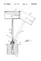
- FIG. 1represents a side elevational view of the present invention holding a mailbox, with the phantom illustration showing the deflection of the structure.
- FIG. 2shows a partial cross-sectional view of the tubular elongated structural member showing the pre-stressed internal spring.
- FIG. 3illustrates a section of an alternate embodiment showing the invention mounted to a platform.
- FIG. 4is a representation of a top view of the illustration shown in FIG. 3.
- FIG. 1where the present invention is generally referred to with numeral 10, it can be observed that it basically includes a tubular elongated structural assembly 20 with a mailbox B mounted on its upper end and the lower end being rigidly mounted to concrete slab S in one of the preferred embodiments.
- Tubular elongated structural assembly 20'is showing in phantom in FIG. 1 showing how it can be deflected through the application of force. After the force ceases, assembly 20' recovers its upright orientation.
- Assembly 20comprises of two sections: upper section 30 and lower section 40 with an internal spring member 50 bringing them towards each other. These two sections are abuttingly and coaxially positioned with respect to each other.
- Rubber cover 60is designed to protect the interface between upper section 30 and lower section 40 from dust and dirt.
- upper section 30starts substantially at ground level and extends upwardly to a suitable distance where mailbox B is mounted to permit the ready withdrawal of mail.
- FIG. 2a detailed cross-sectional view of the abutting section is shown.
- the lower end of upper section 30is threaded and receives threaded flanged ring 32 that comes in contact with similar threaded flanged ring 42.
- Rubber cover 60covers threaded flanged ring 32 completely and part of threaded flanged ring 42. In this manner, more structural stability is introduced to tubular elongated structural assembly 20.
- Spring member 50is housed within tubular elongated structural assembly 20 and it is pre-stressed sufficiently to exert and effective amount of force that urges upper section 30 towards section 40. In this manner, upper section 30 recovers its coaxially disposed position with respect to section 40 which in the preferred embodiment extends upwardly. Different degrees of pretensioning can be achieved by hooking ends 52 and 54 of spring 50 to internal pins 36 and 46 that are transversally disposed inside tubular section 30 and 40, respectively, and are removably inserted through openings 37 and 47. When upper section 20 is deflected, the horizontal component of the spring contraction force is approximately the spring contraction force multiplied by the sine of the angle of deflection.
- the horizontal component of the pre-tensioning forceis approximately the sine of the angle (A) multiplied by the pre-tensioning force magnitude.
- FIGS. 3 and 4 and alternate embodiment for mounting tubular elongated structural assembly 20 showing in phantomit basically consists of using a platform member 70 for users that do not desire to pour a slab.
- Platform member 70in the alternate embodiment, fulfills the function of lower flanged ring 42.
- Recess 72is preferably sufficiently deep to receive lower flanged ring 32'.
- Rubber cover 60'covers upper flanged rings 32', and in the preferred alternate embodiment, cover 60 ' includes a flanged termination 65 that rests against surface 71 of platform member 70.
- Bolt members 64keep flanged termination 65 in place, preferably using circular plate 62 with through openings, thereby preventing the entry of any dirt or foreign bodies between the abutting surfaces of flanged rings 32' and 42'.
Landscapes
- Engineering & Computer Science (AREA)
- Architecture (AREA)
- Civil Engineering (AREA)
- Structural Engineering (AREA)
- Supports Or Holders For Household Use (AREA)
Abstract
Description
1. Field of the Invention
The present invention relates to mailbox stands, and more particularly, to such stands that include a movable structural member.
2. Description of the Related Art
Applicant believes that the closest reference corresponds to U.S. Pat. No. 4,792,088 issued to Bonnell. However, it differs from the present invention because the spring used to provide the moving or pivoting characteristic would not efficiently recover its position when the mailbox is loaded with considerable weight. If a stronger spring is used, then the stand will not avoid the damaging effect of the impact since it will oppose the impact. This reference does not teach pre-stressing the spring in order to insure that the structure recovers its original upright position.
Other patents describing the closest subject matter provide for a number of more or less complicated features that fail to solve the problem in an efficient and economical way. None of these patents suggest the novel features of the present invention.
It is one of the main objects of the present invention to provide a mailbox stand that readily deflects from its upright alignment and recovers when the deflecting force ceases.
It is another object of this present invention to provide a mailbox stand that absorbs the impact with a minimum damage.
It is yet another object of this present invention to provide such a device that is inexpensive to manufacture and maintain while retaining its effectiveness.
Further objects of the invention will be brought out in the following part of the specification, wherein detailed description is for the purpose of fully disclosing the invention without placing limitations thereon.
With the above and other related objects in view, the invention consists in the details of construction and combination of parts as will be more fully understood from the following description, when read in conjunction with the accompanying drawings in which:
FIG. 1 represents a side elevational view of the present invention holding a mailbox, with the phantom illustration showing the deflection of the structure.
FIG. 2 shows a partial cross-sectional view of the tubular elongated structural member showing the pre-stressed internal spring.
FIG. 3 illustrates a section of an alternate embodiment showing the invention mounted to a platform.
FIG. 4 is a representation of a top view of the illustration shown in FIG. 3.
Referring now to FIG. 1, where the present invention is generally referred to withnumeral 10, it can be observed that it basically includes a tubular elongatedstructural assembly 20 with a mailbox B mounted on its upper end and the lower end being rigidly mounted to concrete slab S in one of the preferred embodiments. Tubular elongated structural assembly 20' is showing in phantom in FIG. 1 showing how it can be deflected through the application of force. After the force ceases, assembly 20' recovers its upright orientation.Assembly 20 comprises of two sections:upper section 30 andlower section 40 with aninternal spring member 50 bringing them towards each other. These two sections are abuttingly and coaxially positioned with respect to each other.Rubber cover 60 is designed to protect the interface betweenupper section 30 andlower section 40 from dust and dirt. Preferably,upper section 30 starts substantially at ground level and extends upwardly to a suitable distance where mailbox B is mounted to permit the ready withdrawal of mail.
In FIG. 2, a detailed cross-sectional view of the abutting section is shown. The lower end ofupper section 30 is threaded and receives threaded flangedring 32 that comes in contact with similar threaded flanged ring 42.Rubber cover 60 covers threaded flangedring 32 completely and part of threaded flanged ring 42. In this manner, more structural stability is introduced to tubular elongatedstructural assembly 20.
In FIGS. 3 and 4 and alternate embodiment for mounting tubular elongatedstructural assembly 20 showing in phantom is illustrated it basically consists of using aplatform member 70 for users that do not desire to pour a slab.Platform member 70, in the alternate embodiment, fulfills the function of lower flanged ring 42.Recess 72 is preferably sufficiently deep to receive lower flanged ring 32'. Rubber cover 60' covers upper flanged rings 32', and in the preferred alternate embodiment, cover 60 ' includes a flangedtermination 65 that rests againstsurface 71 ofplatform member 70.Bolt members 64 keep flangedtermination 65 in place, preferably usingcircular plate 62 with through openings, thereby preventing the entry of any dirt or foreign bodies between the abutting surfaces of flanged rings 32' and 42'.
It is believed the foregoing description conveys the best understanding of the objects and advantages of the present invention. Different embodiments may be made of the inventive concept of this invention. It is to be understood that all matter disclosed herein is to be interpreted merely as illustrative, and not in a limiting sense.
Claims (5)
1. A stand for mailboxes mounted to a concrete slab comprising a tubular elongated structural member having an upper section and a lower section, and said sections being coaxially aligned and each having two ends and wherein one of the ends of said upper section is rigidly mounted to said mailbox and one of the ends of said lower section being rigidly mounted to said concrete slab, and the other ends of said upper and lower sections being disposed next to each other and said other ends of said upper and lower sections being disposed next to each other and each one including one flanged ring member rigidly mounted on each of said other ends so that substantial cooperative surfaces from each of said flanged ring members abutting to each other provide substantially structural stability to the stand and further including spring means for urging said upper and lower sections toward each other and said spring means being in a pre-stretched condition and wherein said spring means are internally disposed within said lower and upper sections such that a torsional recovery force and a horizontal component of the spring contraction force acts on the upper section and further including rubber cover means for preventing extraneous bodies from penetrating between said upper and lower sections.
2. The stand set forth in claim 1 further including means for adjusting the pre-stretched condition of said spring means.
3. A stand for mailboxes mounted to a platform member comprising a tubular elongated structural member having an upper section and a lower section, and said sections being coaxially aligned and each having two ends and wherein one of the ends of said upper section is rigidly mounted to said mailbox and one of the ends of said lower section being rigidly mounted to a fixed point in said platform, and the other end of said upper section being disposed next to one of the ends of said lower section having a threaded termination that is cooperatively received through a threaded portion in said platform member and wherein said ends of said upper and lower section being disposed next to each other include, each, one flanged ring member rigidly mounted on each of said other ends so that substantial cooperative surfaces from each of said flanged ring members abutting to each other provide substantially structural stability to the stand and further including spring means for urging said upper and lower sections toward each other and said spring means being a pre-stretched condition and wherein said spring means are internally disposed within said lower and upper sections such that a torsional recovery force and a horizontal component of the spring contraction force acts on the upper section and further including rubber cover means for preventing extraneous bodies from penetrating between said upper and lower sections.
4. The stand set forth in claim 3 wherein said platform includes a sufficiently large recess to house said flanged ring member.
5. The stand set forth in claim 3 wherein said rubber cover means includes a peripheral outwardly extending flanged termination and fastening means for keeping said cover means rigidly in place with respect to said recess.
Priority Applications (2)
| Application Number | Priority Date | Filing Date | Title |
|---|---|---|---|
| US07/601,621US5029783A (en) | 1990-10-23 | 1990-10-23 | Flexible mailbox stand |
| PCT/US1991/001577WO1992007217A1 (en) | 1990-10-23 | 1991-03-11 | Flexible mailbox stand |
Applications Claiming Priority (1)
| Application Number | Priority Date | Filing Date | Title |
|---|---|---|---|
| US07/601,621US5029783A (en) | 1990-10-23 | 1990-10-23 | Flexible mailbox stand |
Publications (1)
| Publication Number | Publication Date |
|---|---|
| US5029783Atrue US5029783A (en) | 1991-07-09 |
Family
ID=24408162
Family Applications (1)
| Application Number | Title | Priority Date | Filing Date |
|---|---|---|---|
| US07/601,621Expired - Fee RelatedUS5029783A (en) | 1990-10-23 | 1990-10-23 | Flexible mailbox stand |
Country Status (2)
| Country | Link |
|---|---|
| US (1) | US5029783A (en) |
| WO (1) | WO1992007217A1 (en) |
Cited By (36)
| Publication number | Priority date | Publication date | Assignee | Title |
|---|---|---|---|---|
| US5090348A (en)* | 1991-03-26 | 1992-02-25 | Hugron Denis P | Traffic signalling post |
| US5149282A (en)* | 1990-08-30 | 1992-09-22 | Lightolier Division Of The Genlyte Group, Inc. | Modular stem system for lighting applications |
| US5205236A (en)* | 1991-07-26 | 1993-04-27 | Flexstake, Inc. | Stiffener core for a highway marker |
| US5207377A (en)* | 1991-08-26 | 1993-05-04 | Brecht Frederick R | Deflectable mailbox |
| US5215283A (en)* | 1992-05-29 | 1993-06-01 | Gould Richard D | Swing-away mailbox support |
| US5356072A (en)* | 1992-12-02 | 1994-10-18 | Thomas Frank P | Mailbox mounting device to absorb lateral impact |
| US5397197A (en)* | 1993-06-04 | 1995-03-14 | Beavers; Dale W. | Resilient bollard with rotatable collar for alerting vehicles of their location |
| US5597262A (en)* | 1995-03-28 | 1997-01-28 | Dale W. Beavers | Resilient traffic bollard with rotatable collar |
| US5678757A (en)* | 1995-05-11 | 1997-10-21 | Martin; Harry W. | Mailbox unit |
| US6099412A (en)* | 1998-11-10 | 2000-08-08 | Weibye; Ronald | Flexible distance marker for golf course |
| US6223982B1 (en)* | 1999-03-05 | 2001-05-01 | Tristram C. Dunn | Impact resistant mailbox support |
| DE10016702A1 (en)* | 2000-04-05 | 2001-10-18 | G A Kettner Gmbh | Sign post or measuring point post has two-section pipe with upper section elastically compliable in relation to lower section by the overcoming of a preferably adjustable transfer force |
| US7032811B1 (en) | 2004-01-16 | 2006-04-25 | Kenneth Paulic | Rotatable mailbox with flexible support |
| US20080013328A1 (en)* | 2006-07-17 | 2008-01-17 | Newbill Anthony J | Yieldable support for a mailbox |
| US20080205067A1 (en)* | 2007-02-28 | 2008-08-28 | Genlyte Thomas Group, Llc | Luminaire Optical Assembly |
| US20080205068A1 (en)* | 2007-02-28 | 2008-08-28 | Genlyte Thomas Group, Llc | Luminaire Optical Assembly |
| US20090057388A1 (en)* | 2006-07-17 | 2009-03-05 | Newbill Anthony J | Yieldable fixture assembly |
| US20090165699A1 (en)* | 2005-01-19 | 2009-07-02 | Dasco Pro, Inc. | Hammer-Driven Snow Pole |
| US20090283659A1 (en)* | 2006-07-17 | 2009-11-19 | Newbill Anthony J | Yieldable assembly |
| US20100143034A1 (en)* | 2008-12-09 | 2010-06-10 | Arra David Yeghiayan | Method and Apparatus for a Roadway Marker |
| US20100212578A1 (en)* | 2005-01-19 | 2010-08-26 | Brad Groves | Caution Pole |
| US20100237143A1 (en)* | 2009-03-17 | 2010-09-23 | Labrecque Jr Maurice J | Flexible mailbox post assembly |
| US20120001051A1 (en)* | 2010-07-01 | 2012-01-05 | Williams Mark N | Rebounding post mounting system |
| USD661609S1 (en) | 2010-06-10 | 2012-06-12 | Fiberglass Innovations, LLC | Caution pole |
| US20130134288A1 (en)* | 2011-11-29 | 2013-05-30 | Michael Webber | Spring post box holder for receiving a mailbox and post arrangement for absorbing impacts, e.g., from snow, slush, ice and water thrown from a plowblade |
| US20140021311A1 (en)* | 2011-07-25 | 2014-01-23 | Arthur W. Lenz, Jr. | Flexible mailbox support with detachable swing arm and replacable outer sleeve |
| US9490525B2 (en)* | 2014-12-22 | 2016-11-08 | Deere & Company | Resilient antenna mast |
| US9808106B1 (en) | 2015-11-24 | 2017-11-07 | John Bihn | Safe rotatable mailbox |
| US20180010308A1 (en)* | 2015-07-03 | 2018-01-11 | Somjit Mandal | Semi rigid joint |
| US9924821B1 (en)* | 2017-06-20 | 2018-03-27 | The Spectrum Services Company Inc. | Flexible mailbox support |
| US10022007B1 (en)* | 2017-05-31 | 2018-07-17 | Daniel Lucero | Mailbox shielding assembly |
| US20190133361A1 (en)* | 2017-11-07 | 2019-05-09 | Kurtis Baun | Pivoting platform for a mailbox |
| US20200018024A1 (en)* | 2018-07-11 | 2020-01-16 | Timothy Allen Steele | Indestructible mailbox post |
| US10582795B1 (en) | 2019-04-02 | 2020-03-10 | Kevin Rawls | Portable secure mailbox system |
| US20230309692A1 (en)* | 2022-03-30 | 2023-10-05 | Guangdong Wireking Housewares & Hardware Co., Ltd | Twistable and stackable shelf and connecting device thereof |
| US20240081571A1 (en)* | 2022-09-08 | 2024-03-14 | William Sieff | Mailbox impact return system |
Families Citing this family (1)
| Publication number | Priority date | Publication date | Assignee | Title |
|---|---|---|---|---|
| FR3013365B1 (en)* | 2013-11-18 | 2016-04-29 | Signaux Girod | AUTORABLEABLE ROAD SIGNALING BEACON |
Citations (15)
| Publication number | Priority date | Publication date | Assignee | Title |
|---|---|---|---|---|
| US1313616A (en)* | 1919-08-19 | walsh | ||
| US1341318A (en)* | 1916-12-22 | 1920-05-25 | Catherine T Hannagan | Traffic-post |
| US1679623A (en)* | 1926-10-25 | 1928-08-07 | Olsen Henry | Signal-post structure |
| US1726817A (en)* | 1928-01-31 | 1929-09-03 | Mark B Franklin | Traffic signal |
| US2009040A (en)* | 1934-11-08 | 1935-07-23 | Frederick H Beach | Punching bag apparatus |
| US2094475A (en)* | 1935-01-26 | 1937-09-28 | Gen Electric | Collapsible antenna for vehicles |
| US2103410A (en)* | 1936-03-20 | 1937-12-28 | Jr John Frei | Post construction |
| US2165704A (en)* | 1938-08-19 | 1939-07-11 | Joseph B Hood | Sign |
| US2949324A (en)* | 1959-03-17 | 1960-08-16 | Birge Homer | Flexible sign post |
| FR1540430A (en)* | 1966-07-28 | 1968-09-27 | Wilhelm Elbracht & Co K G | Flexible beacon for road and urban signs |
| FR2408706A1 (en)* | 1977-09-23 | 1979-06-08 | Massiera Rene | Post for marking ski-run - has tubular sections coupled by tensioned core cable and connectors to allow deformation on impact |
| US4270873A (en)* | 1979-04-13 | 1981-06-02 | Rapidgate, Inc. | Pivotable delineator post |
| US4373464A (en)* | 1980-05-27 | 1983-02-15 | Blau & Lapides, Inc. | Resilient dome device |
| US4636109A (en)* | 1984-12-21 | 1987-01-13 | Allsop, Inc. | Hinged slalom gate |
| US4792088A (en)* | 1988-02-18 | 1988-12-20 | Raymond Bonnell | Indestructible mailbox |
- 1990
- 1990-10-23USUS07/601,621patent/US5029783A/ennot_activeExpired - Fee Related
- 1991
- 1991-03-11WOPCT/US1991/001577patent/WO1992007217A1/enunknown
Patent Citations (15)
| Publication number | Priority date | Publication date | Assignee | Title |
|---|---|---|---|---|
| US1313616A (en)* | 1919-08-19 | walsh | ||
| US1341318A (en)* | 1916-12-22 | 1920-05-25 | Catherine T Hannagan | Traffic-post |
| US1679623A (en)* | 1926-10-25 | 1928-08-07 | Olsen Henry | Signal-post structure |
| US1726817A (en)* | 1928-01-31 | 1929-09-03 | Mark B Franklin | Traffic signal |
| US2009040A (en)* | 1934-11-08 | 1935-07-23 | Frederick H Beach | Punching bag apparatus |
| US2094475A (en)* | 1935-01-26 | 1937-09-28 | Gen Electric | Collapsible antenna for vehicles |
| US2103410A (en)* | 1936-03-20 | 1937-12-28 | Jr John Frei | Post construction |
| US2165704A (en)* | 1938-08-19 | 1939-07-11 | Joseph B Hood | Sign |
| US2949324A (en)* | 1959-03-17 | 1960-08-16 | Birge Homer | Flexible sign post |
| FR1540430A (en)* | 1966-07-28 | 1968-09-27 | Wilhelm Elbracht & Co K G | Flexible beacon for road and urban signs |
| FR2408706A1 (en)* | 1977-09-23 | 1979-06-08 | Massiera Rene | Post for marking ski-run - has tubular sections coupled by tensioned core cable and connectors to allow deformation on impact |
| US4270873A (en)* | 1979-04-13 | 1981-06-02 | Rapidgate, Inc. | Pivotable delineator post |
| US4373464A (en)* | 1980-05-27 | 1983-02-15 | Blau & Lapides, Inc. | Resilient dome device |
| US4636109A (en)* | 1984-12-21 | 1987-01-13 | Allsop, Inc. | Hinged slalom gate |
| US4792088A (en)* | 1988-02-18 | 1988-12-20 | Raymond Bonnell | Indestructible mailbox |
Cited By (48)
| Publication number | Priority date | Publication date | Assignee | Title |
|---|---|---|---|---|
| US5149282A (en)* | 1990-08-30 | 1992-09-22 | Lightolier Division Of The Genlyte Group, Inc. | Modular stem system for lighting applications |
| US5090348A (en)* | 1991-03-26 | 1992-02-25 | Hugron Denis P | Traffic signalling post |
| US5205236A (en)* | 1991-07-26 | 1993-04-27 | Flexstake, Inc. | Stiffener core for a highway marker |
| US5207377A (en)* | 1991-08-26 | 1993-05-04 | Brecht Frederick R | Deflectable mailbox |
| US5215283A (en)* | 1992-05-29 | 1993-06-01 | Gould Richard D | Swing-away mailbox support |
| US5356072A (en)* | 1992-12-02 | 1994-10-18 | Thomas Frank P | Mailbox mounting device to absorb lateral impact |
| US5397197A (en)* | 1993-06-04 | 1995-03-14 | Beavers; Dale W. | Resilient bollard with rotatable collar for alerting vehicles of their location |
| US5597262A (en)* | 1995-03-28 | 1997-01-28 | Dale W. Beavers | Resilient traffic bollard with rotatable collar |
| US5678757A (en)* | 1995-05-11 | 1997-10-21 | Martin; Harry W. | Mailbox unit |
| US6099412A (en)* | 1998-11-10 | 2000-08-08 | Weibye; Ronald | Flexible distance marker for golf course |
| US6223982B1 (en)* | 1999-03-05 | 2001-05-01 | Tristram C. Dunn | Impact resistant mailbox support |
| DE10016702A1 (en)* | 2000-04-05 | 2001-10-18 | G A Kettner Gmbh | Sign post or measuring point post has two-section pipe with upper section elastically compliable in relation to lower section by the overcoming of a preferably adjustable transfer force |
| DE10016702B4 (en)* | 2000-04-05 | 2006-04-27 | G.A. Kettner Gmbh | Sign and / or Meßstellenpost |
| US7032811B1 (en) | 2004-01-16 | 2006-04-25 | Kenneth Paulic | Rotatable mailbox with flexible support |
| US7748745B2 (en)* | 2005-01-19 | 2010-07-06 | Fiberglass Innovations, LLC | Hammer-driven snow pole |
| US8439401B2 (en) | 2005-01-19 | 2013-05-14 | Fiberglass Innovations, LLC | Caution pole |
| US20090165699A1 (en)* | 2005-01-19 | 2009-07-02 | Dasco Pro, Inc. | Hammer-Driven Snow Pole |
| US7644953B2 (en)* | 2005-01-19 | 2010-01-12 | Fiberglass Innovations, LLC | Hammer-driven snow pole |
| US20100212578A1 (en)* | 2005-01-19 | 2010-08-26 | Brad Groves | Caution Pole |
| US20090057388A1 (en)* | 2006-07-17 | 2009-03-05 | Newbill Anthony J | Yieldable fixture assembly |
| US20090283659A1 (en)* | 2006-07-17 | 2009-11-19 | Newbill Anthony J | Yieldable assembly |
| US20080013328A1 (en)* | 2006-07-17 | 2008-01-17 | Newbill Anthony J | Yieldable support for a mailbox |
| US7794123B2 (en) | 2006-07-17 | 2010-09-14 | Newbill Anthony J | Yieldable support for a mailbox |
| US20080205068A1 (en)* | 2007-02-28 | 2008-08-28 | Genlyte Thomas Group, Llc | Luminaire Optical Assembly |
| US7631990B2 (en) | 2007-02-28 | 2009-12-15 | Genlyte Thomas Group Llc | Luminaire housing and lens mounting assembly |
| US7645055B2 (en) | 2007-02-28 | 2010-01-12 | Genlyte Thomas Group, Llc | Luminaire optical assembly |
| US20080205067A1 (en)* | 2007-02-28 | 2008-08-28 | Genlyte Thomas Group, Llc | Luminaire Optical Assembly |
| US20100143034A1 (en)* | 2008-12-09 | 2010-06-10 | Arra David Yeghiayan | Method and Apparatus for a Roadway Marker |
| US20100237143A1 (en)* | 2009-03-17 | 2010-09-23 | Labrecque Jr Maurice J | Flexible mailbox post assembly |
| USD661609S1 (en) | 2010-06-10 | 2012-06-12 | Fiberglass Innovations, LLC | Caution pole |
| US20120001051A1 (en)* | 2010-07-01 | 2012-01-05 | Williams Mark N | Rebounding post mounting system |
| US9433313B2 (en)* | 2011-07-25 | 2016-09-06 | Arthur W. Lenz, Jr. | Flexible mailbox support with detachable swing arm and replacable outer sleeve |
| US20140021311A1 (en)* | 2011-07-25 | 2014-01-23 | Arthur W. Lenz, Jr. | Flexible mailbox support with detachable swing arm and replacable outer sleeve |
| US20130134288A1 (en)* | 2011-11-29 | 2013-05-30 | Michael Webber | Spring post box holder for receiving a mailbox and post arrangement for absorbing impacts, e.g., from snow, slush, ice and water thrown from a plowblade |
| US9490525B2 (en)* | 2014-12-22 | 2016-11-08 | Deere & Company | Resilient antenna mast |
| US20180010308A1 (en)* | 2015-07-03 | 2018-01-11 | Somjit Mandal | Semi rigid joint |
| US9808106B1 (en) | 2015-11-24 | 2017-11-07 | John Bihn | Safe rotatable mailbox |
| US10022007B1 (en)* | 2017-05-31 | 2018-07-17 | Daniel Lucero | Mailbox shielding assembly |
| US9924821B1 (en)* | 2017-06-20 | 2018-03-27 | The Spectrum Services Company Inc. | Flexible mailbox support |
| US10098490B1 (en) | 2017-06-20 | 2018-10-16 | The Spectrum Services Company Inc. | Flexible mailbox support |
| US20190133361A1 (en)* | 2017-11-07 | 2019-05-09 | Kurtis Baun | Pivoting platform for a mailbox |
| US10687647B2 (en)* | 2017-11-07 | 2020-06-23 | Kurtis Baun | Pivoting platform for a mailbox |
| US20200018024A1 (en)* | 2018-07-11 | 2020-01-16 | Timothy Allen Steele | Indestructible mailbox post |
| US11028544B2 (en)* | 2018-07-11 | 2021-06-08 | Timothy Allen Steele | Indestructible mailbox post |
| US10582795B1 (en) | 2019-04-02 | 2020-03-10 | Kevin Rawls | Portable secure mailbox system |
| US20230309692A1 (en)* | 2022-03-30 | 2023-10-05 | Guangdong Wireking Housewares & Hardware Co., Ltd | Twistable and stackable shelf and connecting device thereof |
| US12317999B2 (en)* | 2022-03-30 | 2025-06-03 | Guangdong Wireking Housewares & Hardware Co., Ltd | Twistable and stackable shelf and connecting device thereof |
| US20240081571A1 (en)* | 2022-09-08 | 2024-03-14 | William Sieff | Mailbox impact return system |
Also Published As
| Publication number | Publication date |
|---|---|
| WO1992007217A1 (en) | 1992-04-30 |
Similar Documents
| Publication | Publication Date | Title |
|---|---|---|
| US5029783A (en) | Flexible mailbox stand | |
| US6039298A (en) | Tapered steel post | |
| US5791635A (en) | Fence post with anchor | |
| US7617792B1 (en) | Bumper assembly for posts and pilings | |
| US5515656A (en) | Portable anchorage and fastener | |
| US5318258A (en) | Portable highway sign stand | |
| US4257490A (en) | Portable observation stand | |
| US3199818A (en) | Lantern stand | |
| US4974378A (en) | Seismic-isolator | |
| GB2229411A (en) | Bypassing double action rope grip | |
| US5371907A (en) | Pool cover support | |
| CA2070885A1 (en) | Universal Pole Anchoring Device | |
| WO1994018491A1 (en) | Christmas tree stand | |
| US4130239A (en) | Swing-away mailbox | |
| US5788416A (en) | Portable modular dock system | |
| CA1109443A (en) | Post support | |
| US4065103A (en) | Fence attachment | |
| EP0334821A3 (en) | A device for the supporting without a central post and the winch opening of large sunshades and similar | |
| US5172891A (en) | Safe road railing | |
| US5971344A (en) | Method of using an open book securing device for hands-free reading of an open book | |
| US5501479A (en) | Kickstand bumper | |
| US6112690A (en) | Watercraft docking system | |
| US6178909B1 (en) | Water craft and dock protector assembly | |
| US4395012A (en) | Support for a mailbox | |
| US3521285A (en) | Antenna mount |
Legal Events
| Date | Code | Title | Description |
|---|---|---|---|
| REMI | Maintenance fee reminder mailed | ||
| FPAY | Fee payment | Year of fee payment:4 | |
| SULP | Surcharge for late payment | ||
| REMI | Maintenance fee reminder mailed | ||
| LAPS | Lapse for failure to pay maintenance fees | ||
| FP | Lapsed due to failure to pay maintenance fee | Effective date:19990709 | |
| STCH | Information on status: patent discontinuation | Free format text:PATENT EXPIRED DUE TO NONPAYMENT OF MAINTENANCE FEES UNDER 37 CFR 1.362 |