US5027996A - Method of manufacturing a hollow shaft with internal swellings of revolution and shaft obtained by this method - Google Patents
Method of manufacturing a hollow shaft with internal swellings of revolution and shaft obtained by this methodDownload PDFInfo
- Publication number
- US5027996A US5027996AUS07/471,741US47174190AUS5027996AUS 5027996 AUS5027996 AUS 5027996AUS 47174190 AUS47174190 AUS 47174190AUS 5027996 AUS5027996 AUS 5027996A
- Authority
- US
- United States
- Prior art keywords
- blank
- punch
- internal
- sections
- revolution
- Prior art date
- Legal status (The legal status is an assumption and is not a legal conclusion. Google has not performed a legal analysis and makes no representation as to the accuracy of the status listed.)
- Expired - Lifetime
Links
- 206010042674SwellingDiseases0.000titleclaimsabstractdescription25
- 230000008961swellingEffects0.000titleclaimsabstractdescription25
- 238000000034methodMethods0.000titleclaimsabstractdescription13
- 238000004519manufacturing processMethods0.000titleclaimsabstractdescription7
- 238000003754machiningMethods0.000claimsdescription8
- 238000003466weldingMethods0.000claimsdescription6
- 238000010438heat treatmentMethods0.000claimsdescription2
- 238000003825pressingMethods0.000claims1
- 238000000641cold extrusionMethods0.000abstractdescription6
- 230000015572biosynthetic processEffects0.000abstractdescription2
- 238000001125extrusionMethods0.000description4
- 238000002485combustion reactionMethods0.000description3
- 229910000831SteelInorganic materials0.000description1
- 239000011324beadSubstances0.000description1
- 238000003801millingMethods0.000description1
- 238000004080punchingMethods0.000description1
- 238000010008shearingMethods0.000description1
- 239000010959steelSubstances0.000description1
- 239000002699waste materialSubstances0.000description1
Images

Classifications
- B—PERFORMING OPERATIONS; TRANSPORTING
- B21—MECHANICAL METAL-WORKING WITHOUT ESSENTIALLY REMOVING MATERIAL; PUNCHING METAL
- B21K—MAKING FORGED OR PRESSED METAL PRODUCTS, e.g. HORSE-SHOES, RIVETS, BOLTS OR WHEELS
- B21K1/00—Making machine elements
- B21K1/06—Making machine elements axles or shafts
- F—MECHANICAL ENGINEERING; LIGHTING; HEATING; WEAPONS; BLASTING
- F16—ENGINEERING ELEMENTS AND UNITS; GENERAL MEASURES FOR PRODUCING AND MAINTAINING EFFECTIVE FUNCTIONING OF MACHINES OR INSTALLATIONS; THERMAL INSULATION IN GENERAL
- F16J—PISTONS; CYLINDERS; SEALINGS
- F16J1/00—Pistons; Trunk pistons; Plungers
- F16J1/10—Connection to driving members
- F16J1/14—Connection to driving members with connecting-rods, i.e. pivotal connections
- F16J1/16—Connection to driving members with connecting-rods, i.e. pivotal connections with gudgeon-pin; Gudgeon-pins
Definitions
- the present inventionrelates first of all to a method of manufacturing a hollow shaft with internal swellings of revolution, which consists in forming first of all hollow shaft sections each comprising at least one internal swelling of revolution, then in assembling two sections coaxially end to end so as to obtain a hollow shaft comprising internally at least two swellings of revolution.
- the method of manufacturing the shaft sectionsrequires the use of two punching dies acting against a blank in two opposite directions, with each time the necessity of taking the thus hollowed blank from the die, which represents a long and difficult operation. Then, it is advisable to perforate the central web with a tool such as a milling cutter, which is an additional operation and which means that this is an essentially discontinuous method with reduced productivity.
- the object of the present inventionis to overcome these drawbacks of the prior art and, for this, provides a method of manufacturing a hollow shaft with internal swellings of revolution in accordance with the invention of the general type defined at the beginning, which is essentially characterized in that said sections are formed by cold extrusion operations using a single punch, without removal of the part and without subsequent machining, these extrusion operations comprising:
- a method in accordance with the inventionmay be further characterized in that said insert piece is formed by the next blank, which contributes to making the method substantially continuous and allows high productivity to be obtained; it should be noted that the blank enters through one end of the die and is pushed therethrough always in the same direction and leaves through its other end, which avoids any waste of time.
- the inventionalso relates to a hollow shaft intended in particular to provide the connection between the connecting rod small end and an internal combustion engine piston, this shaft being profiled inwardly so as to have at least two swellings of revolution, at the level of the zone or zones likely to be subjected to the highest forces, namely at the level of its respective shearing planes, this shaft being characterized in that it is manufactured according to the method which has just been defined.
- This shaftmay in particular be characterized by the fact that the internal swelling of revolution of each section has a practically sinusoidal profile, this being obtained directly at the outlet of the cold extrusion die, without any subsequent machining.
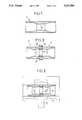
- FIG. 1is an axial sectional view of a sinusoidal shaft section in accordance with the invention, with central internal swelling;
- FIG. 2is an axial sectional view of two shaft sections similar to those of FIG. 1 (but shorter) butt-jointed by a friction welding operation, these two sections thus forming a shaft blank;
- FIG. 3is an axial sectional view of the finished shaft obtained by external machining of the blank of FIG. 2;
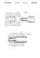
- FIGS. 4 to 7are schematic axial sectional views of the die and of the cold extrusion punch for the shaft sections, showing the different extrusion steps.
- the shaft section 1 of FIG. 1for example made from blister steel, comprises inwardly a swelling of revolution 2. It can be seen that it extends centrally over practically a third of the length of the section. Of course, its extent in length could be less.
- two sections 1may first of all be manufactured similar to that of FIG. 1, and welded end to end. This is what has been shown in FIG. 2, in which the sections have been referenced 1 and 1' and their respective internal swellings 2 and 2'.
- the external 3, 3' and internal 4, 4' beadsare due to the method of welding by inertia (or by friction): the two sections are aligned, one is driven in rotation and the other, which is fixed, is pressed thereagainst for contacting the two surfaces; the friction heating which results causes welding thereof, at which moment of course positive driving thereof is stopped.
- FIG. 3shows the finished shaft, obtained by externally machining the blank of FIG. 2.
- the bearings 5 of the internal combustion enginehave been shown with phantom lines, which this shaft 1--1' is supposed to connect to the connecting rod small end 6.
- FIG. 4shows a tubular blank 1a placed in the die and FIG. 5 its deformation 1b, after engagement of the tip 10 of the punch in its axial passage 11. It can be seen that the rear end of the blank is pressed by shoulder 13 of the punch and that its front end is extruded, being compressed between tip 10 of the punch and the narrowed orifice 14 of the die.
- the punch 7is then removed and a new blank 12 is introduced in die 8, behind blank 1b.
Landscapes
- Engineering & Computer Science (AREA)
- General Engineering & Computer Science (AREA)
- Mechanical Engineering (AREA)
- Chemical & Material Sciences (AREA)
- Combustion & Propulsion (AREA)
- Forging (AREA)
- Pistons, Piston Rings, And Cylinders (AREA)
- Shafts, Cranks, Connecting Bars, And Related Bearings (AREA)
- Extrusion Moulding Of Plastics Or The Like (AREA)
- Extrusion Of Metal (AREA)
Abstract
Description
Claims (4)
Applications Claiming Priority (2)
| Application Number | Priority Date | Filing Date | Title |
|---|---|---|---|
| FR8901036AFR2642474B1 (en) | 1989-01-27 | 1989-01-27 | HOLLOW SHAFT, ESPECIALLY FOR AN INTERNAL COMBUSTION ENGINE PISTON, AND ITS MANUFACTURING METHOD |
| FR8901036 | 1989-01-27 |
Publications (1)
| Publication Number | Publication Date |
|---|---|
| US5027996Atrue US5027996A (en) | 1991-07-02 |
Family
ID=9378182
Family Applications (1)
| Application Number | Title | Priority Date | Filing Date |
|---|---|---|---|
| US07/471,741Expired - LifetimeUS5027996A (en) | 1989-01-27 | 1990-01-29 | Method of manufacturing a hollow shaft with internal swellings of revolution and shaft obtained by this method |
Country Status (6)
| Country | Link |
|---|---|
| US (1) | US5027996A (en) |
| EP (1) | EP0381556B1 (en) |
| JP (1) | JPH06100280B2 (en) |
| DE (1) | DE69007309T2 (en) |
| ES (1) | ES2053130T3 (en) |
| FR (1) | FR2642474B1 (en) |
Cited By (20)
| Publication number | Priority date | Publication date | Assignee | Title |
|---|---|---|---|---|
| US5213250A (en)* | 1991-12-19 | 1993-05-25 | Simon Joseph A | Method for forming a lightweight flanged axle shaft |
| US5431325A (en)* | 1993-12-27 | 1995-07-11 | Ford Motor Company | Method and apparatus for producing hermetic torque converter seam |
| US20040089099A1 (en)* | 2002-11-13 | 2004-05-13 | Federal-Mogul World Wide, Inc. | Wrist pin |
| US20060218985A1 (en)* | 2003-04-11 | 2006-10-05 | Kazuhito Kenmochi | Tube with high dimensional accuracy, and method and device for manufacturing the tube |
| US20080245230A1 (en)* | 2007-04-04 | 2008-10-09 | Roberto Bueno Nigro | Piston assembly and wrist pin therefor providing a method of controlling rotation of the wrist pin within corresponding piston pin bores and connecting rod wrist pin bore |
| RU2356680C1 (en)* | 2006-08-11 | 2009-05-27 | Бургесс-Нортон Мфг. Ко. | Manufacturing method of piston pin and piston pin, manufactured by this method |
| US20100232870A1 (en)* | 2009-03-12 | 2010-09-16 | Delaware Capital Formation, Inc. | Selectively reinforced piston pin |
| US20110160645A1 (en)* | 2009-12-31 | 2011-06-30 | Boston Scientific Scimed, Inc. | Cryo Activated Drug Delivery and Cutting Balloons |
| US20110196340A1 (en)* | 1997-08-13 | 2011-08-11 | Boston Scientific Scimed, Inc. | Loading and release of water-insoluble drugs |
| US20120283031A1 (en)* | 2009-12-10 | 2012-11-08 | Jtekt Corporation | Propeller shaft |
| US8597720B2 (en) | 2007-01-21 | 2013-12-03 | Hemoteq Ag | Medical product for treating stenosis of body passages and for preventing threatening restenosis |
| US8669360B2 (en) | 2011-08-05 | 2014-03-11 | Boston Scientific Scimed, Inc. | Methods of converting amorphous drug substance into crystalline form |
| US8889211B2 (en) | 2010-09-02 | 2014-11-18 | Boston Scientific Scimed, Inc. | Coating process for drug delivery balloons using heat-induced rewrap memory |
| US9056152B2 (en) | 2011-08-25 | 2015-06-16 | Boston Scientific Scimed, Inc. | Medical device with crystalline drug coating |
| US9192697B2 (en) | 2007-07-03 | 2015-11-24 | Hemoteq Ag | Balloon catheter for treating stenosis of body passages and for preventing threatening restenosis |
| US20160008917A1 (en)* | 2013-03-28 | 2016-01-14 | Kayaba Industry Co., Ltd. | Joined body |
| WO2017154375A1 (en)* | 2016-03-08 | 2017-09-14 | 日立オートモティブシステムズ株式会社 | Piston pin and method for manufacturing piston pin |
| US10080821B2 (en) | 2009-07-17 | 2018-09-25 | Boston Scientific Scimed, Inc. | Nucleation of drug delivery balloons to provide improved crystal size and density |
| US10369256B2 (en) | 2009-07-10 | 2019-08-06 | Boston Scientific Scimed, Inc. | Use of nanocrystals for drug delivery from a balloon |
| US20210277933A1 (en)* | 2020-03-06 | 2021-09-09 | Honda Motor Co., Ltd. | Drive shaft and method of producing drive shaft |
Families Citing this family (3)
| Publication number | Priority date | Publication date | Assignee | Title |
|---|---|---|---|---|
| DE10029950A1 (en)* | 2000-06-26 | 2002-01-03 | Volkswagen Ag | connecting rod |
| EP1621265A1 (en)* | 2003-04-11 | 2006-02-01 | JFE Steel Corporation | Tube with high dimensional accuracy, and method and device for manufacturing the tube |
| JP4285053B2 (en)* | 2003-04-11 | 2009-06-24 | Jfeスチール株式会社 | High dimensional accuracy tube and manufacturing method thereof |
Citations (2)
| Publication number | Priority date | Publication date | Assignee | Title |
|---|---|---|---|---|
| US4677722A (en)* | 1985-12-16 | 1987-07-07 | Chrysler Motors Corporation | Tapered piston pin |
| US4712941A (en)* | 1985-12-16 | 1987-12-15 | Chrysler Motors Corporation | Tapered piston pin |
Family Cites Families (2)
| Publication number | Priority date | Publication date | Assignee | Title |
|---|---|---|---|---|
| FR2293262A1 (en)* | 1974-12-06 | 1976-07-02 | Simon Joseph | Extruding tubes with inwardly thickened ends - by partial extrusion followed by full extrusion with a second blank |
| DE3521796A1 (en)* | 1985-06-19 | 1987-01-02 | Kolbenschmidt Ag | PISTON PIN |
- 1989
- 1989-01-27FRFR8901036Apatent/FR2642474B1/ennot_activeExpired - Lifetime
- 1990
- 1990-01-24EPEP90400208Apatent/EP0381556B1/ennot_activeExpired - Lifetime
- 1990-01-24ESES90400208Tpatent/ES2053130T3/ennot_activeExpired - Lifetime
- 1990-01-24DEDE69007309Tpatent/DE69007309T2/ennot_activeExpired - Fee Related
- 1990-01-29USUS07/471,741patent/US5027996A/ennot_activeExpired - Lifetime
- 1990-01-29JPJP2016288Apatent/JPH06100280B2/ennot_activeExpired - Lifetime
Patent Citations (2)
| Publication number | Priority date | Publication date | Assignee | Title |
|---|---|---|---|---|
| US4677722A (en)* | 1985-12-16 | 1987-07-07 | Chrysler Motors Corporation | Tapered piston pin |
| US4712941A (en)* | 1985-12-16 | 1987-12-15 | Chrysler Motors Corporation | Tapered piston pin |
Cited By (27)
| Publication number | Priority date | Publication date | Assignee | Title |
|---|---|---|---|---|
| US5213250A (en)* | 1991-12-19 | 1993-05-25 | Simon Joseph A | Method for forming a lightweight flanged axle shaft |
| US5431325A (en)* | 1993-12-27 | 1995-07-11 | Ford Motor Company | Method and apparatus for producing hermetic torque converter seam |
| US20110196340A1 (en)* | 1997-08-13 | 2011-08-11 | Boston Scientific Scimed, Inc. | Loading and release of water-insoluble drugs |
| US20040089099A1 (en)* | 2002-11-13 | 2004-05-13 | Federal-Mogul World Wide, Inc. | Wrist pin |
| US20060218985A1 (en)* | 2003-04-11 | 2006-10-05 | Kazuhito Kenmochi | Tube with high dimensional accuracy, and method and device for manufacturing the tube |
| RU2356680C1 (en)* | 2006-08-11 | 2009-05-27 | Бургесс-Нортон Мфг. Ко. | Manufacturing method of piston pin and piston pin, manufactured by this method |
| US8597720B2 (en) | 2007-01-21 | 2013-12-03 | Hemoteq Ag | Medical product for treating stenosis of body passages and for preventing threatening restenosis |
| US20080245230A1 (en)* | 2007-04-04 | 2008-10-09 | Roberto Bueno Nigro | Piston assembly and wrist pin therefor providing a method of controlling rotation of the wrist pin within corresponding piston pin bores and connecting rod wrist pin bore |
| US7603944B2 (en) | 2007-04-04 | 2009-10-20 | Federal-Mogul World Wide, Inc. | Piston assembly and wrist pin therefor providing a method of controlling rotation of the wrist pin within corresponding piston pin bores and connecting rod wrist pin bore |
| US9192697B2 (en) | 2007-07-03 | 2015-11-24 | Hemoteq Ag | Balloon catheter for treating stenosis of body passages and for preventing threatening restenosis |
| US20100232870A1 (en)* | 2009-03-12 | 2010-09-16 | Delaware Capital Formation, Inc. | Selectively reinforced piston pin |
| US11278648B2 (en) | 2009-07-10 | 2022-03-22 | Boston Scientific Scimed, Inc. | Use of nanocrystals for drug delivery from a balloon |
| US10369256B2 (en) | 2009-07-10 | 2019-08-06 | Boston Scientific Scimed, Inc. | Use of nanocrystals for drug delivery from a balloon |
| US10080821B2 (en) | 2009-07-17 | 2018-09-25 | Boston Scientific Scimed, Inc. | Nucleation of drug delivery balloons to provide improved crystal size and density |
| US20120283031A1 (en)* | 2009-12-10 | 2012-11-08 | Jtekt Corporation | Propeller shaft |
| US8814028B2 (en)* | 2009-12-10 | 2014-08-26 | Jtekt Corporation | Method of removing bulging portions to manufacture a friction welded propeller shaft |
| US20110160645A1 (en)* | 2009-12-31 | 2011-06-30 | Boston Scientific Scimed, Inc. | Cryo Activated Drug Delivery and Cutting Balloons |
| US8889211B2 (en) | 2010-09-02 | 2014-11-18 | Boston Scientific Scimed, Inc. | Coating process for drug delivery balloons using heat-induced rewrap memory |
| US8669360B2 (en) | 2011-08-05 | 2014-03-11 | Boston Scientific Scimed, Inc. | Methods of converting amorphous drug substance into crystalline form |
| US9056152B2 (en) | 2011-08-25 | 2015-06-16 | Boston Scientific Scimed, Inc. | Medical device with crystalline drug coating |
| US10065265B2 (en)* | 2013-03-28 | 2018-09-04 | Kyb Corporation | Joined body |
| US20160008917A1 (en)* | 2013-03-28 | 2016-01-14 | Kayaba Industry Co., Ltd. | Joined body |
| WO2017154375A1 (en)* | 2016-03-08 | 2017-09-14 | 日立オートモティブシステムズ株式会社 | Piston pin and method for manufacturing piston pin |
| CN108884936A (en)* | 2016-03-08 | 2018-11-23 | 日立汽车系统株式会社 | The manufacturing method of piston pin and piston pin |
| US20190076913A1 (en)* | 2016-03-08 | 2019-03-14 | Hitachi Automotive Systems, Ltd. | Piston pin and method for manufacturing piston pin |
| US20210277933A1 (en)* | 2020-03-06 | 2021-09-09 | Honda Motor Co., Ltd. | Drive shaft and method of producing drive shaft |
| US11965548B2 (en)* | 2020-03-06 | 2024-04-23 | Honda Motor Co., Ltd. | Drive shaft and method of producing drive shaft |
Also Published As
| Publication number | Publication date |
|---|---|
| DE69007309T2 (en) | 1994-06-23 |
| FR2642474A1 (en) | 1990-08-03 |
| FR2642474B1 (en) | 1992-05-15 |
| EP0381556B1 (en) | 1994-03-16 |
| DE69007309D1 (en) | 1994-04-21 |
| JPH06100280B2 (en) | 1994-12-12 |
| JPH02283964A (en) | 1990-11-21 |
| EP0381556A1 (en) | 1990-08-08 |
| ES2053130T3 (en) | 1994-07-16 |
Similar Documents
| Publication | Publication Date | Title |
|---|---|---|
| US5027996A (en) | Method of manufacturing a hollow shaft with internal swellings of revolution and shaft obtained by this method | |
| CA2334216C (en) | Method of forming a tubular member | |
| US7032286B2 (en) | Method of making steel couplers for joining concrete reinforcing bars | |
| US4641546A (en) | Crankshaft assembly for small gasoline motors | |
| US5125256A (en) | Method of manufacturing outside ring | |
| US5957777A (en) | Method of manufacturing fasteners | |
| US6293164B1 (en) | Rack and pinion steering apparatus and method for manufacturing a helical pinion | |
| EP1268097B1 (en) | Method for making a tubular assembly having hydroformed interconnecting member | |
| US6266878B1 (en) | Process for producing variable displacement compressor pistons having hollow piston bodies and integral actuator rods | |
| US4815906A (en) | Blind rivet assembly | |
| US4722211A (en) | Method of forming hollow parts | |
| US4450704A (en) | Metal sleeve production | |
| DE69406609T2 (en) | Process for producing the mandrel of a blind rivet | |
| GB2067445A (en) | Closed chamber extrusion of metal rod into tulip-shaped part | |
| US4601192A (en) | Method of producing an expansion sleeve for a metallic expansion dowel assembly | |
| GB2114474A (en) | Forging steel blanks | |
| JPS60261638A (en) | Manufacture of gear provided with boss | |
| JPS6061134A (en) | Working method of valve-like formed article | |
| SU984598A1 (en) | Blank for producing hollow cylindrical articles | |
| KR830001460B1 (en) | Metal member joining method | |
| JPS6123546A (en) | Production of fork end shaped-body | |
| JPH044939A (en) | Method for forming intermediate joint fitting for hydraulic piping or the like | |
| JPS6130251A (en) | Cold forging method and device for products with tooth profile | |
| JPH0698432B2 (en) | Method for manufacturing columnar body with uneven pattern on both ends | |
| EP0776712A1 (en) | Method for the production of a special screw for hinges in furniture and screws obtained with this method |
Legal Events
| Date | Code | Title | Description |
|---|---|---|---|
| AS | Assignment | Owner name:FLOQUET MONOPOLE, FRANCE Free format text:ASSIGNMENT OF ASSIGNORS INTEREST.;ASSIGNORS:FEFEU, MICHEL A.;PERRIN, GERARD L.;REEL/FRAME:005269/0670 Effective date:19900302 | |
| FEPP | Fee payment procedure | Free format text:PAYOR NUMBER ASSIGNED (ORIGINAL EVENT CODE: ASPN); ENTITY STATUS OF PATENT OWNER: LARGE ENTITY | |
| STCF | Information on status: patent grant | Free format text:PATENTED CASE | |
| FEPP | Fee payment procedure | Free format text:PAYER NUMBER DE-ASSIGNED (ORIGINAL EVENT CODE: RMPN); ENTITY STATUS OF PATENT OWNER: LARGE ENTITY Free format text:PAYOR NUMBER ASSIGNED (ORIGINAL EVENT CODE: ASPN); ENTITY STATUS OF PATENT OWNER: LARGE ENTITY | |
| FPAY | Fee payment | Year of fee payment:4 | |
| AS | Assignment | Owner name:PERFECT CIRCLE EUROPE, FRANCE Free format text:CHANGE OF NAME;ASSIGNOR:MONOPOLE, FLOQUET;REEL/FRAME:008587/0418 Effective date:19960531 | |
| FEPP | Fee payment procedure | Free format text:PAYOR NUMBER ASSIGNED (ORIGINAL EVENT CODE: ASPN); ENTITY STATUS OF PATENT OWNER: LARGE ENTITY Free format text:PAYER NUMBER DE-ASSIGNED (ORIGINAL EVENT CODE: RMPN); ENTITY STATUS OF PATENT OWNER: LARGE ENTITY | |
| FPAY | Fee payment | Year of fee payment:8 | |
| FPAY | Fee payment | Year of fee payment:12 | |
| REMI | Maintenance fee reminder mailed |