US5027861A - Flow control fitting enabling high flow rates - Google Patents
Flow control fitting enabling high flow ratesDownload PDFInfo
- Publication number
- US5027861A US5027861AUS07/605,918US60591890AUS5027861AUS 5027861 AUS5027861 AUS 5027861AUS 60591890 AUS60591890 AUS 60591890AUS 5027861 AUS5027861 AUS 5027861A
- Authority
- US
- United States
- Prior art keywords
- disk
- axial bore
- flow control
- shaped member
- housing
- Prior art date
- Legal status (The legal status is an assumption and is not a legal conclusion. Google has not performed a legal analysis and makes no representation as to the accuracy of the status listed.)
- Expired - Lifetime
Links
Images

Classifications
- F—MECHANICAL ENGINEERING; LIGHTING; HEATING; WEAPONS; BLASTING
- F16—ENGINEERING ELEMENTS AND UNITS; GENERAL MEASURES FOR PRODUCING AND MAINTAINING EFFECTIVE FUNCTIONING OF MACHINES OR INSTALLATIONS; THERMAL INSULATION IN GENERAL
- F16L—PIPES; JOINTS OR FITTINGS FOR PIPES; SUPPORTS FOR PIPES, CABLES OR PROTECTIVE TUBING; MEANS FOR THERMAL INSULATION IN GENERAL
- F16L55/00—Devices or appurtenances for use in, or in connection with, pipes or pipe systems
- F16L55/02—Energy absorbers; Noise absorbers
- F16L55/027—Throttle passages
Definitions
- the present inventionrelates to a flow controller and, more particularly, to a flow control washer.
- washer-type flow controllersSeveral different applications exist for washer-type flow controllers. Particularly, in the automotive industry, especially in heating systems, it is desirable to enable fluid to flow as rapidly as possible through a conduit or heater core until a desired flow rate is achieved. Once the desired flow rate is achieved, the flow rate should be maintained at the desired level as pressure increases.
- a washer controllerTo accomplish relatively high flow rates at relative low pressure, since the controller itself is a restriction in the conduit, a washer controller must enable maximum fluid flow passage through the conduit. As the pressure of the fluid in the conduit increases, the flow rate through the conduit increases. The washer controller enables the flow rate to increase at a desired rate until the desired flow rate is achieved then the controller maintains the flow rate at the desired level as the pressure in the conduit continues to increase.
- the present inventionprovides the art with a washer-type control device which enables maximum flow at low pressures and a constant desired flow as pressure continues to increase.
- FIG. 1is a perspective view of a fluid control device in accordance with the present invention.
- FIG. 2is a vertical cross-section view of FIG. 1 through the plane designated by line 2--2 thereof.
- FIG. 3is a vertical cross-section view of FIG. 1 taken through the plane designated by line 3--3 thereof.
- FIG. 4is a vertical cross-section view like that of FIG. 3 illustrating low pressure flow through the device.
- FIG. 5is a vertical cross-section view like that of FIG. 4 illustrating medium pressure flow through the device.
- FIG. 6is a vertical cross-section view like that of FIG. 4 illustrating high pressure flow through the device.
- FIG. 7is a graph illustrating flow rate with respect to pressure.
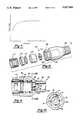
- FIG. 8is an exploded perspective view of a fitting in accordance with the present invention.
- FIG. 9is a vertical axial cross-section view of the assembled device of FIG. 8 through the plane designated by line 9--9 thereof.
- the flow control device 15generally includes a body member 10 With one or more positioning members 12, 14, 16, 18 and a lip 20.
- the body 10is disk shaped having a pair of major faces 24 and 26 with an axial bore 22 therethrough.
- Major face 24is substantially planar.
- Major face 26is inwardly tapered at the angle of from about 21° to about 25° and preferably at about 23°. The innermost periphery of the taper abuts the lip 20.
- Major face 26also includes an outer planar ring 28 at the outer periphery of the taper. The outer planar ring 28 is substantially parallel with major face 24.
- the positioning members 12-18are unitarily formed with the disk member 10.
- the positioning members 12-18project from the exterior circumferential wall 30 of the disk member 10.
- the tops of positioning members 12-18are ordinarily flush with the planar ring 28 and extend beyond planar major face 24 providing the disk member 10 with one or more legs.
- the positioning members 12-18position the disk 10 circumferentially and axially away from a wall, housing or the like.
- the positioning members 12-18enable fluid to flow around and under the disk member 10 as illustrated in FIG. 4. It should be noted that four positioning members are illustrated, however, a lesser number may be used as long as they provide for fluid to flow around and under the disk member 10.
- the lip 20is positioned peripherally about the axial bore 22.
- the lip 20, in cross-section,has a frustrum shape.
- One side wall 40 of the frustrumis continuous with the interior wall of the axial bore 22.
- the other side wall 42 of the frustrumextends at an angle from about 26° to about 31°, preferably at 28.8°, with respect to side wall 40.
- the top surface 44 of the frustrumis substantially planar and forms an annular ring about the axial bore.
- Side wall 42 and the tapered major face 26form an obtuse angle with respect to one another.
- the lip 20projects from the innermost portion of the taper such that the top surface ring 44 is in a plane parallel with and below a plane defined by the ring 28. Thus, the lip 20 does not extend beyond a plane defined by the planar ring 28.
- the lip 20is generally positioned such that the top surface ring 44 is located a distance of approximately 0.58 millimeters below the plane of the planar ring 28. This positioning prevents the lip 20 from collapsing or sphinctering closed terminating flow. Also, the lip 20 provides a flow area through the axial bore 22, at high pressure, to insure the desired constant flow rate as illustrated by the graph of FIG. 7.
- the fluid flowpasses through the axial bore 22 and around and the disk member 10 as illustrated in FIG. 4.
- the disk member 10 and positioning means 12-18deflect pressing against a wall terminating the flow from around the disk member 10 as seen in FIG. 5.
- the lip 20deflects into the axial bore 22 maintaining the fluid flow at a desired rate as illustrated in FIG. 6.
- the disk member -0, positioning members 12-18 and lip 20are unitarily formed from an elastomeric resilient material.
- the elastomeric materialis of a durometer of between 65-75.
- the elastomeris generally of a medium high acrylic content nitrile rubber, blackloaded compound.
- the tensile strength of the materialis generally from about 1800 to 2600 psi.
- the percent elongation of the materialis between 380 to 520 percent.
- the modulus of elasticity of the material at 100 percentis between 375 psi to 525 psi; at 200 percent it is between 950 psi to 1250 psi; at 300 percent, it is between 1500 psi to 2000 psi.
- the percent flow area underneath the positioning members and around the disk memberis about 57 percent of the flow at low pressure while the flow through the axial bore is approximately 43 percent of the flow.
- the fitting 60generally includes a housing 62 having a pair of ends 64 and 66 and an axial bore 68 running through the entire housing 62.
- the ends 64 and 66are adapted to readily connect to a conduit or the like.
- end 64has a threaded exterior and end 66 is adapted with a quick connect mechanism.
- the axial bore 68has a stepped design having a step 70 to receive the flow controller 15 as seen in FIGS. 9 and 10.
- a retainer 72, O-ring 74 and a flow controller positioning member 76are positioned within the fitting 60.
- a quick connect retainer 77is coupled with end 66.
- the flow controller 15is sandwiched between the step 70 and positioning member 76.
- the positioning members 12, 14, 16 and 18maintain the disk member 10 away from the housing wall 70 and the retainer 76.
Landscapes
- Engineering & Computer Science (AREA)
- General Engineering & Computer Science (AREA)
- Mechanical Engineering (AREA)
- Valve Housings (AREA)
Abstract
Description
Claims (8)
Priority Applications (1)
| Application Number | Priority Date | Filing Date | Title |
|---|---|---|---|
| US07/605,918US5027861A (en) | 1989-03-07 | 1990-10-30 | Flow control fitting enabling high flow rates |
Applications Claiming Priority (2)
| Application Number | Priority Date | Filing Date | Title |
|---|---|---|---|
| US07/319,961US4986312A (en) | 1989-03-07 | 1989-03-07 | Flow control device |
| US07/605,918US5027861A (en) | 1989-03-07 | 1990-10-30 | Flow control fitting enabling high flow rates |
Related Parent Applications (1)
| Application Number | Title | Priority Date | Filing Date |
|---|---|---|---|
| US07/319,961ContinuationUS4986312A (en) | 1989-03-07 | 1989-03-07 | Flow control device |
Publications (1)
| Publication Number | Publication Date |
|---|---|
| US5027861Atrue US5027861A (en) | 1991-07-02 |
Family
ID=26982223
Family Applications (1)
| Application Number | Title | Priority Date | Filing Date |
|---|---|---|---|
| US07/605,918Expired - LifetimeUS5027861A (en) | 1989-03-07 | 1990-10-30 | Flow control fitting enabling high flow rates |
Country Status (1)
| Country | Link |
|---|---|
| US (1) | US5027861A (en) |
Cited By (24)
| Publication number | Priority date | Publication date | Assignee | Title |
|---|---|---|---|---|
| US5318073A (en)* | 1992-06-09 | 1994-06-07 | Daniel Industries, Inc. | Orifice plate seal |
| US5409042A (en)* | 1993-07-29 | 1995-04-25 | Romac Industries, Inc. | Constant-rate flow control valve |
| US5505229A (en)* | 1993-07-12 | 1996-04-09 | The Lee Company | Fluid resistor |
| US5560669A (en)* | 1994-08-10 | 1996-10-01 | Lear Corporation | Fastenerless retainer assembly |
| US5607193A (en)* | 1994-01-13 | 1997-03-04 | Guest; John D. | Tube couplings |
| US5904177A (en)* | 1997-03-17 | 1999-05-18 | Marotta Scientific Controls, Inc. | Fluid flow control device |
| US6299128B1 (en)* | 1998-07-31 | 2001-10-09 | Zurn Industries, Inc. | Diaphragm orifice for flushometer |
| US6308646B1 (en)* | 2000-03-20 | 2001-10-30 | Deere & Company | Tuning orifice for pneumatic metering manifold |
| US6571831B1 (en)* | 1999-07-13 | 2003-06-03 | Dieter Wildfang Gmbh | Flow regulator |
| US20060086393A1 (en)* | 2004-10-22 | 2006-04-27 | Vernay Laboratories, Inc. | Flow-control valve assembly |
| US20060086399A1 (en)* | 2004-10-21 | 2006-04-27 | Bailey James C | Internal post flow control |
| US20070170111A1 (en)* | 2006-01-20 | 2007-07-26 | Gwan Ho Ro | Solenoid valve for controlling water supply |
| US20110139284A1 (en)* | 2009-12-15 | 2011-06-16 | 3M Innovative Properties Company | Diluted-fluid dispensing device with pressure-compensating passive valve |
| US20110297263A1 (en)* | 2010-06-03 | 2011-12-08 | Mark Atkins | Flow restrictor |
| US8287495B2 (en) | 2009-07-30 | 2012-10-16 | Tandem Diabetes Care, Inc. | Infusion pump system with disposable cartridge having pressure venting and pressure feedback |
| US8408421B2 (en) | 2008-09-16 | 2013-04-02 | Tandem Diabetes Care, Inc. | Flow regulating stopcocks and related methods |
| US8650937B2 (en) | 2008-09-19 | 2014-02-18 | Tandem Diabetes Care, Inc. | Solute concentration measurement device and related methods |
| US20140332097A1 (en)* | 2011-05-17 | 2014-11-13 | Neoperl Gmbh | Flow-volume regulator |
| US8986253B2 (en) | 2008-01-25 | 2015-03-24 | Tandem Diabetes Care, Inc. | Two chamber pumps and related methods |
| US20170022693A1 (en)* | 2015-07-22 | 2017-01-26 | Long Tai Copper Corporation | Flow-control faucet aerator |
| US20180036748A1 (en)* | 2015-03-09 | 2018-02-08 | Neoperl Gmbh | Sanitary insertion unit |
| US9962486B2 (en) | 2013-03-14 | 2018-05-08 | Tandem Diabetes Care, Inc. | System and method for detecting occlusions in an infusion pump |
| US10258736B2 (en) | 2012-05-17 | 2019-04-16 | Tandem Diabetes Care, Inc. | Systems including vial adapter for fluid transfer |
| US10401877B2 (en) | 2017-12-19 | 2019-09-03 | Nelson Irrigation Corporation | Flow washer assembly |
Citations (9)
| Publication number | Priority date | Publication date | Assignee | Title |
|---|---|---|---|---|
| US2728355A (en)* | 1953-10-30 | 1955-12-27 | Dole Valve Co | By-pass flow washer |
| US2815041A (en)* | 1955-11-22 | 1957-12-03 | Dole Valve Co | Single solenoid hydraulic control valve |
| US2829674A (en)* | 1954-06-11 | 1958-04-08 | August L Segelhorst | Automatic fluid control means |
| US2878836A (en)* | 1957-05-13 | 1959-03-24 | Scovill Manufacturing Co | Two-piece flow control valve |
| US3995664A (en)* | 1975-03-13 | 1976-12-07 | Nelson Walter R | Flow control device |
| US4508144A (en)* | 1983-11-28 | 1985-04-02 | Eaton Corporation | Flow control device |
| US4609014A (en)* | 1985-10-25 | 1986-09-02 | Vernay Laboratories, Inc. | Variable rate flow controller |
| US4667700A (en)* | 1984-11-22 | 1987-05-26 | Hans Grohe Gmbh & Co. | Apparatus for throttling flow limitation in water fittings |
| US4754897A (en)* | 1986-02-11 | 1988-07-05 | Bespak Plc | Gas pressurized dispensing containers |
- 1990
- 1990-10-30USUS07/605,918patent/US5027861A/ennot_activeExpired - Lifetime
Patent Citations (9)
| Publication number | Priority date | Publication date | Assignee | Title |
|---|---|---|---|---|
| US2728355A (en)* | 1953-10-30 | 1955-12-27 | Dole Valve Co | By-pass flow washer |
| US2829674A (en)* | 1954-06-11 | 1958-04-08 | August L Segelhorst | Automatic fluid control means |
| US2815041A (en)* | 1955-11-22 | 1957-12-03 | Dole Valve Co | Single solenoid hydraulic control valve |
| US2878836A (en)* | 1957-05-13 | 1959-03-24 | Scovill Manufacturing Co | Two-piece flow control valve |
| US3995664A (en)* | 1975-03-13 | 1976-12-07 | Nelson Walter R | Flow control device |
| US4508144A (en)* | 1983-11-28 | 1985-04-02 | Eaton Corporation | Flow control device |
| US4667700A (en)* | 1984-11-22 | 1987-05-26 | Hans Grohe Gmbh & Co. | Apparatus for throttling flow limitation in water fittings |
| US4609014A (en)* | 1985-10-25 | 1986-09-02 | Vernay Laboratories, Inc. | Variable rate flow controller |
| US4754897A (en)* | 1986-02-11 | 1988-07-05 | Bespak Plc | Gas pressurized dispensing containers |
Cited By (41)
| Publication number | Priority date | Publication date | Assignee | Title |
|---|---|---|---|---|
| US5318073A (en)* | 1992-06-09 | 1994-06-07 | Daniel Industries, Inc. | Orifice plate seal |
| US5505229A (en)* | 1993-07-12 | 1996-04-09 | The Lee Company | Fluid resistor |
| US5409042A (en)* | 1993-07-29 | 1995-04-25 | Romac Industries, Inc. | Constant-rate flow control valve |
| US5607193A (en)* | 1994-01-13 | 1997-03-04 | Guest; John D. | Tube couplings |
| US5560669A (en)* | 1994-08-10 | 1996-10-01 | Lear Corporation | Fastenerless retainer assembly |
| US5904177A (en)* | 1997-03-17 | 1999-05-18 | Marotta Scientific Controls, Inc. | Fluid flow control device |
| US6467750B2 (en) | 1998-07-31 | 2002-10-22 | Zurn Industries, Inc. | Diaphragm orifice for flushometer |
| US6299128B1 (en)* | 1998-07-31 | 2001-10-09 | Zurn Industries, Inc. | Diaphragm orifice for flushometer |
| US6571831B1 (en)* | 1999-07-13 | 2003-06-03 | Dieter Wildfang Gmbh | Flow regulator |
| US6308646B1 (en)* | 2000-03-20 | 2001-10-30 | Deere & Company | Tuning orifice for pneumatic metering manifold |
| US20060086399A1 (en)* | 2004-10-21 | 2006-04-27 | Bailey James C | Internal post flow control |
| US7222643B2 (en) | 2004-10-21 | 2007-05-29 | Vernay Laboratories, Inc. | Internal post flow control |
| US20060086393A1 (en)* | 2004-10-22 | 2006-04-27 | Vernay Laboratories, Inc. | Flow-control valve assembly |
| US7225829B2 (en) | 2004-10-22 | 2007-06-05 | Vernay Laboratories, Inc. | Flow-control valve assembly |
| US20070170111A1 (en)* | 2006-01-20 | 2007-07-26 | Gwan Ho Ro | Solenoid valve for controlling water supply |
| US7546999B2 (en)* | 2006-01-20 | 2009-06-16 | Useong Electro Mechanics Co., Ltd. | Solenoid valve for controlling water supply |
| US8986253B2 (en) | 2008-01-25 | 2015-03-24 | Tandem Diabetes Care, Inc. | Two chamber pumps and related methods |
| US8408421B2 (en) | 2008-09-16 | 2013-04-02 | Tandem Diabetes Care, Inc. | Flow regulating stopcocks and related methods |
| US8448824B2 (en) | 2008-09-16 | 2013-05-28 | Tandem Diabetes Care, Inc. | Slideable flow metering devices and related methods |
| US8650937B2 (en) | 2008-09-19 | 2014-02-18 | Tandem Diabetes Care, Inc. | Solute concentration measurement device and related methods |
| US9211377B2 (en) | 2009-07-30 | 2015-12-15 | Tandem Diabetes Care, Inc. | Infusion pump system with disposable cartridge having pressure venting and pressure feedback |
| US12144964B2 (en) | 2009-07-30 | 2024-11-19 | Tandem Diabetes Care, Inc | Infusion pump system with disposable cartridge having pressure venting and pressure feedback |
| US8298184B2 (en) | 2009-07-30 | 2012-10-30 | Tandem Diabetes Care, Inc. | Infusion pump system with disposable cartridge having pressure venting and pressure feedback |
| US8758323B2 (en) | 2009-07-30 | 2014-06-24 | Tandem Diabetes Care, Inc. | Infusion pump system with disposable cartridge having pressure venting and pressure feedback |
| US11135362B2 (en) | 2009-07-30 | 2021-10-05 | Tandem Diabetes Care, Inc. | Infusion pump systems and methods |
| US11285263B2 (en) | 2009-07-30 | 2022-03-29 | Tandem Diabetes Care, Inc. | Infusion pump systems and methods |
| US8926561B2 (en) | 2009-07-30 | 2015-01-06 | Tandem Diabetes Care, Inc. | Infusion pump system with disposable cartridge having pressure venting and pressure feedback |
| US12042627B2 (en) | 2009-07-30 | 2024-07-23 | Tandem Diabetes Care, Inc. | Infusion pump systems and methods |
| US8287495B2 (en) | 2009-07-30 | 2012-10-16 | Tandem Diabetes Care, Inc. | Infusion pump system with disposable cartridge having pressure venting and pressure feedback |
| US20110139284A1 (en)* | 2009-12-15 | 2011-06-16 | 3M Innovative Properties Company | Diluted-fluid dispensing device with pressure-compensating passive valve |
| US20110297263A1 (en)* | 2010-06-03 | 2011-12-08 | Mark Atkins | Flow restrictor |
| US8899272B2 (en)* | 2010-06-03 | 2014-12-02 | Mark Atkins | Flow restrictor |
| US9377128B2 (en)* | 2011-05-17 | 2016-06-28 | Neoperl Gmbh | Flow-volume regulator |
| US20140332097A1 (en)* | 2011-05-17 | 2014-11-13 | Neoperl Gmbh | Flow-volume regulator |
| US10258736B2 (en) | 2012-05-17 | 2019-04-16 | Tandem Diabetes Care, Inc. | Systems including vial adapter for fluid transfer |
| US9962486B2 (en) | 2013-03-14 | 2018-05-08 | Tandem Diabetes Care, Inc. | System and method for detecting occlusions in an infusion pump |
| US10512920B2 (en)* | 2015-03-09 | 2019-12-24 | Neoperl Gmbh | Sanitary insertion unit |
| US20180036748A1 (en)* | 2015-03-09 | 2018-02-08 | Neoperl Gmbh | Sanitary insertion unit |
| US9822515B2 (en)* | 2015-07-22 | 2017-11-21 | Long Tai Copper Corporation | Flow-control faucet aerator |
| US20170022693A1 (en)* | 2015-07-22 | 2017-01-26 | Long Tai Copper Corporation | Flow-control faucet aerator |
| US10401877B2 (en) | 2017-12-19 | 2019-09-03 | Nelson Irrigation Corporation | Flow washer assembly |
Similar Documents
| Publication | Publication Date | Title |
|---|---|---|
| US5027861A (en) | Flow control fitting enabling high flow rates | |
| US4986312A (en) | Flow control device | |
| US2762397A (en) | Flow control device | |
| US4196753A (en) | Flow regulator | |
| US4938259A (en) | Fluid flow controller | |
| CA2038246C (en) | Normally closed duckbill valve assembly | |
| US5351709A (en) | Control valves | |
| US2484815A (en) | Tube coupling | |
| US6453940B1 (en) | Insert bonded combination valve | |
| US4577653A (en) | Anti-siphon and anti-knock diverter valve | |
| US5944050A (en) | Pressure relief or back pressure valve | |
| US4243616A (en) | Air diffuser | |
| DE2119613A1 (en) | check valve | |
| US3047239A (en) | Nozzle construction | |
| US5409042A (en) | Constant-rate flow control valve | |
| US2834379A (en) | Fluid flow control unit | |
| TW348074B (en) | Throttle valve and shower head with the same | |
| US3949780A (en) | Two piece check valve | |
| US4619287A (en) | Valves proper for valve-type fluid-flow controllers | |
| US3472484A (en) | Sealing means for valve ports | |
| KR830003031A (en) | valve | |
| DE3563256D1 (en) | Butterfly valve for aggressive fluids | |
| US3905386A (en) | Valve | |
| US5062448A (en) | Double action check valve | |
| GB2316474A (en) | Waterheaters |
Legal Events
| Date | Code | Title | Description |
|---|---|---|---|
| STCF | Information on status: patent grant | Free format text:PATENTED CASE | |
| FEPP | Fee payment procedure | Free format text:PAYOR NUMBER ASSIGNED (ORIGINAL EVENT CODE: ASPN); ENTITY STATUS OF PATENT OWNER: LARGE ENTITY Free format text:PAYER NUMBER DE-ASSIGNED (ORIGINAL EVENT CODE: RMPN); ENTITY STATUS OF PATENT OWNER: LARGE ENTITY | |
| FEPP | Fee payment procedure | Free format text:PAYOR NUMBER ASSIGNED (ORIGINAL EVENT CODE: ASPN); ENTITY STATUS OF PATENT OWNER: LARGE ENTITY | |
| AS | Assignment | Owner name:HURON PRODUCTS INDUSTRIES, INC., MICHIGAN Free format text:MERGER;ASSIGNOR:HURON PRODUCTS CORPORATION;REEL/FRAME:006653/0072 Effective date:19891218 Owner name:HURON ACQUISITION CO., WHICH CHANGED ITS NAME TO H Free format text:CHANGE OF NAME;ASSIGNOR:HURON PRODUCTS INDUSTRIES, INC.;REEL/FRAME:006653/0062 Effective date:19910621 Owner name:BUNDY CORPORATION, MICHIGAN Free format text:MERGER;ASSIGNOR:HURON PRODUCTS, INC.;REEL/FRAME:006653/0055 Effective date:19930331 | |
| CC | Certificate of correction | ||
| FPAY | Fee payment | Year of fee payment:4 | |
| FPAY | Fee payment | Year of fee payment:8 | |
| AS | Assignment | Owner name:TI GROUP AUTOMOTIVE SYSTEMS CORPORATION, MICHIGAN Free format text:CHANGE OF NAME;ASSIGNOR:BUNDY CORPORATION;REEL/FRAME:010859/0541 Effective date:19991012 | |
| FEPP | Fee payment procedure | Free format text:PAYER NUMBER DE-ASSIGNED (ORIGINAL EVENT CODE: RMPN); ENTITY STATUS OF PATENT OWNER: LARGE ENTITY Free format text:PAYOR NUMBER ASSIGNED (ORIGINAL EVENT CODE: ASPN); ENTITY STATUS OF PATENT OWNER: LARGE ENTITY | |
| AS | Assignment | Owner name:TI GROUP AUTOMOTIVE SYSTEMS, LLC, MICHIGAN Free format text:MERGER;ASSIGNOR:TI GROUP AUTOMOTIVE SYSTEMS CORPORATION;REEL/FRAME:012407/0436 Effective date:20010625 | |
| FPAY | Fee payment | Year of fee payment:12 | |
| AS | Assignment | Owner name:JPMORGAN CHASE BANK, N.A., NEW YORK Free format text:SECURITY AGREEMENT;ASSIGNORS:HANIL USA, L.L.C.;TI AUTOMOTIVE, L.L.C.;TI GROUP AUTOMOTIVE SYSTEMS, L.L.C.;REEL/FRAME:019733/0933 Effective date:20070629 Owner name:JPMORGAN CHASE BANK, N.A.,NEW YORK Free format text:SECURITY AGREEMENT;ASSIGNORS:HANIL USA, L.L.C.;TI AUTOMOTIVE, L.L.C.;TI GROUP AUTOMOTIVE SYSTEMS, L.L.C.;REEL/FRAME:019733/0933 Effective date:20070629 | |
| AS | Assignment | Owner name:TI GROUP AUTOMOTIVE SYSTEMS, L.L.C., MICHIGAN Free format text:RELEASE BY SECURED PARTY;ASSIGNOR:WILMINGTON TRUST (LONDON) LIMITED;REEL/FRAME:027861/0890 Effective date:20120314 Owner name:HANIL USA, L.L.C., MICHIGAN Free format text:RELEASE BY SECURED PARTY;ASSIGNOR:WILMINGTON TRUST (LONDON) LIMITED;REEL/FRAME:027861/0890 Effective date:20120314 Owner name:WILMINGTON TRUST (LONDON) LIMITED, UNITED KINGDOM Free format text:ASSIGNMENT OF SECURITY INTEREST;ASSIGNOR:JPMORGAN CHASE BANK, N.A.;REEL/FRAME:027861/0815 Effective date:20120314 Owner name:TI AUTOMOTIVE, L.L.C., MICHIGAN Free format text:RELEASE BY SECURED PARTY;ASSIGNOR:WILMINGTON TRUST (LONDON) LIMITED;REEL/FRAME:027861/0890 Effective date:20120314 | |
| AS | Assignment | Owner name:CITIBANK, N.A., DELAWARE Free format text:SUPPLEMENTARY PATENT SECURITY AGREEMENT;ASSIGNORS:TI GROUP AUTOMOTIVE SYSTEMS, L.L.C.;TI AUTOMOTIVE LIMITED;TI AUTOMOTIVE CANADA, INC.;AND OTHERS;REEL/FRAME:030105/0133 Effective date:20130328 Owner name:JPMORGAN CHASE BANK, N.A., NEW YORK Free format text:SUPPLEMENTARY PATENT SECURITY AGREEMENT;ASSIGNORS:TI GROUP AUTOMOTIVE SYSTEMS, L.L.C.;TI AUTOMOTIVE LIMITED;TI AUTOMOTIVE CANADA, INC.;AND OTHERS;REEL/FRAME:030105/0279 Effective date:20130328 | |
| AS | Assignment | Owner name:TI AUTOMOTIVE, L.L.C., MICHIGAN Free format text:TERMINATION AND RELEASE;ASSIGNOR:JPMORGAN CHASE BANK, N.A., AS ADMINISTRATIVE AGENT;REEL/FRAME:036013/0775 Effective date:20150630 Owner name:TI GROUP AUTOMOTIVE SYSTEMS, L.L.C., MICHIGAN Free format text:TERMINATION AND RELEASE;ASSIGNOR:JPMORGAN CHASE BANK, N.A., AS ADMINISTRATIVE AGENT;REEL/FRAME:036013/0775 Effective date:20150630 Owner name:HANIL USA L.L.C., ALABAMA Free format text:TERMINATION AND RELEASE;ASSIGNOR:JPMORGAN CHASE BANK, N.A., AS ADMINISTRATIVE AGENT;REEL/FRAME:036013/0775 Effective date:20150630 Owner name:TI GROUP AUTOMOTIVE SYSTEMS S DE R.L. DE C.V., MEX Free format text:TERMINATION AND RELEASE;ASSIGNOR:JPMORGAN CHASE BANK, N.A., AS ADMINISTRATIVE AGENT;REEL/FRAME:036013/0775 Effective date:20150630 Owner name:TI AUTOMOTIVE CANADA, INC., CANADA Free format text:TERMINATION AND RELEASE;ASSIGNOR:JPMORGAN CHASE BANK, N.A., AS ADMINISTRATIVE AGENT;REEL/FRAME:036013/0775 Effective date:20150630 Owner name:TI AUTOMOTIVE LIMITED, UNITED KINGDOM Free format text:TERMINATION AND RELEASE;ASSIGNOR:JPMORGAN CHASE BANK, N.A., AS ADMINISTRATIVE AGENT;REEL/FRAME:036013/0775 Effective date:20150630 | |
| AS | Assignment | Owner name:TI GROUP AUTOMOTIVE SYSTEMS, L.L.C., MICHIGAN Free format text:TERMINATION AND RELEASE OF PATENT SECURITY INTEREST;ASSIGNOR:CITIBANK, N.A.;REEL/FRAME:036047/0305 Effective date:20150630 |