US5027027A - Electromechanical translation apparatus - Google Patents
Electromechanical translation apparatusDownload PDFInfo
- Publication number
- US5027027A US5027027AUS07/382,853US38285389AUS5027027AUS 5027027 AUS5027027 AUS 5027027AUS 38285389 AUS38285389 AUS 38285389AUS 5027027 AUS5027027 AUS 5027027A
- Authority
- US
- United States
- Prior art keywords
- driven member
- center
- rear elements
- activating
- steps
- Prior art date
- Legal status (The legal status is an assumption and is not a legal conclusion. Google has not performed a legal analysis and makes no representation as to the accuracy of the status listed.)
- Expired - Fee Related
Links
Images


Classifications
- H—ELECTRICITY
- H02—GENERATION; CONVERSION OR DISTRIBUTION OF ELECTRIC POWER
- H02N—ELECTRIC MACHINES NOT OTHERWISE PROVIDED FOR
- H02N2/00—Electric machines in general using piezoelectric effect, electrostriction or magnetostriction
- H02N2/02—Electric machines in general using piezoelectric effect, electrostriction or magnetostriction producing linear motion, e.g. actuators; Linear positioners ; Linear motors
- H02N2/021—Electric machines in general using piezoelectric effect, electrostriction or magnetostriction producing linear motion, e.g. actuators; Linear positioners ; Linear motors using intermittent driving, e.g. step motors, piezoleg motors
- H02N2/023—Inchworm motors
- H—ELECTRICITY
- H02—GENERATION; CONVERSION OR DISTRIBUTION OF ELECTRIC POWER
- H02N—ELECTRIC MACHINES NOT OTHERWISE PROVIDED FOR
- H02N2/00—Electric machines in general using piezoelectric effect, electrostriction or magnetostriction
- H02N2/02—Electric machines in general using piezoelectric effect, electrostriction or magnetostriction producing linear motion, e.g. actuators; Linear positioners ; Linear motors
- H02N2/06—Drive circuits; Control arrangements or methods
Definitions
- the present inventionrelates generally to electromechanical translation apparatus and particularly to inchworm linear motors which are capable of motion in incremental steps and to methods and apparatus for operating inchworm linear motors.
- Inchworm linear motorsare compact piezoelectromechanical actuators and known for use in apparatus such as linear actuators and positioners.
- piezoelectric electromechanical translation apparatusDisclosed in U.S. Pat. No. 3,902,084, and incorporated by reference herein, is piezoelectric electromechanical translation apparatus, the load activating shaft of which extends through a housing and is programmably movable over long distances with extremely fine resolution, in extremely small incremental steps by a piezoelectric driver which has three driver sections in end-to-end relationship around the shaft and which is referenced to the housing.
- the driveris operative to clamp the shaft, and when a staircase voltage is applied to an element thereof, translates the shaft in a direction and over an incremental distance related to the polarity and amplitude of the steps of the staircase voltage. Staircase voltage cycles may be repeated to move the shaft incrementally over a long distance.
- electromechanical translation apparatuswhich provides translation with a high degree of uniformity of motion.
- the deviceincludes a piezoelectric driver having three driver sections arranged in end-to-end relationship around the shaft.
- This driveris referenced to a housing and provides forces for moving the shaft with respect to the housing.
- the sections of the driverare interconnected by bridging members which assemble the driver sections in integral relationship and yet allow movement of the driver sections into and out of engagement with the shaft without imparting undersired motion to the shaft.
- Operation of the apparatus disclosed in the two above-referenced U.S. Patentscomprises a sequence of steps which involve applying voltages to the driver sections which, for purposes of clarity, will be referred to as forward, center and rear sections with respect to the desired direction of movement of a shaft about which the driver is arranged.
- a voltageis applied to the forward section thus causing it to clamp the shaft.
- a variable rate staircase voltageis applied to the center section causing it to expand and, as the driver is mounted fixed in relation to its housing, the forward section is pushed forward by the extent of the expansion of the center section and, therefore, moves the shaft in a forward direction along a corresponding distance.
- a voltageis then applied to the rear section causing it to clamp the shaft and the voltage on the forward section is subsequently removed, the grip of the forward section on the shaft, therefore, being loosened.
- the staircase voltageits upper limit having been reached prior to the voltage being applied to the rear section, then starts downward towards its lower limit, causing the center section to contract to its original length. After the center section has contracted, a voltage is then applied to the forward section causing it to clamp the shaft, and the sequence of steps outlined above are repeated.
- a disadvantage of the apparatus described aboveis that in the sequence of steps which constitute its operation, there are steps which involve the simultaneous clamping of the shaft by both the forward and rear sections of the driver.
- a method of moving along a travel axis and in a selected direction a driven membercomprising the steps of providing translation apparatus including a driver mounted in a fixed position relative to a base, the driver comprising selectably operable forward, center and rear elements coupled in series and associated with the driven member and being arranged parallel to the travel axis, the forward and rear elements comprising apparatus for clamping the driven member and the center element comprising apparatus for varying the distance between the forward and rear elements; and in a series of distinct steps, operating the forward, center and rear elements so as to cause movement of the driven member relative to the base including, steps of operation, partially overlapping in time, of the forward and center elements and the center and rear elements and steps of operation, non-overlapping in time, of the forward and rear elements.
- the steps of operating the forward, center and rear elementscomprise the sub-steps of activating the forward element so as to cause clamping of the driven member thereby; activating in a first mode the center element so as to increase the distance between the forward and rear elements, thus causing movement of the forward element and the driven member relative to the base and in the selected direction; deactivating the forward element, thus causing release of the driven member therefrom; activating in a second mode the center element so as to reduce the distance between the forward and rear elements and thus cause a rearward movement of the forward element relative to the direction of movement of the driven member, while activating the rear element so as to clamp therewith the driven member; deactivating the rear element once the center element is almost completely deactivated, thus effecting release therefrom of the driven member; and activating in the first mode the center element so as to increase the distance between the forward and rear elements, while activating the forward element so as to cause clamping of the driven member thereby.
- the translation apparatuscomprises electromechanical translation apparatus.
- the forward, center and rear elementsare formed of a piezoelectric material and the step of activating each of the forward and rear elements comprises the step of applying a voltage thereacross, and the steps of activating the center element in the first and second modes comprise the steps of applying a voltage across the center element and diminishing it therefrom, respectively.
- a method of moving along a travel axis and in a selected direction, a driven membercomprising the steps of providing translation apparatus including a driver mounted in a fixed position relative to a base, the driver comprising selectably operable forward, center and rear elements coupled in series and associated with the driven member and being arranged parallel to the travel axis, the forward and rear elements comprising apparatus for clamping the driven member and the center element comprising apparatus for varying the distance between the forward and rear elements; accelerating the driven member by operating the forward, center and rear elements so as to cause travel of the driven member relative to the base in the selected direction along the travel axis; and operating, subsequent to the step of accelerating, in a series of distinct steps, the forward, center and rear elements so as cause faster travel of the driven member relative to the base including steps of operation, partially overlapping in time, of the forward and center elements and the center and rear elements and steps of operation, non-overlapping in time, of the forward and rear elements.
- the step of acceleratingcomprises the sub-steps of activating the forward element so as to cause thereby clamping of the driven member; activating in a first mode the center element so as to increase the distance between the forward and rear elements, thus causing movement of the forward element and the driven member relative to the base and in the selected direction; activating the rear element so as to cause clamping thereby of the driven member; deactivating the forward element so as to cause release therefrom of the driven member; activating in a second mode the center element so as to reduce the distance between the forward and rear elements and thus cause a rearward movement of the driven member; and activating the forward element so as to cause clamping thereby of the driven member.
- the steps of operating the forward, center and rear elements, subsequent to the step of acceleratingcomprise the sub-steps of activating the forward element so as to cause clamping of the driven member thereby; activating in a first mode the center element so as to increase the distance between the forward and rear elements, thus causing movement of the forward element and the driven member relative to the base and in the selected direction; deactivating the forward element, thus causing release of the driven member therefrom; activating in a second mode the center element so as to gradually reduce the distance between the forward and rear elements and thus cause a rearward movement of the forward element relative to the direction of movement of the driven member, while activating the rear element so as to clamp therewith the driven member; deactivating the rear element once the center element is almost completely deactivated, thus effecting release therefrom of the driven member; and activating in the first mode the center element so as to increase the distance between the forward and rear elements, while activating the forward element so as to cause clamping of the driven member thereby.
- the forward, center and rear elementsare formed of a piezoelectric material and the step of activating each of the forward and rear elements comprises the step of applying a voltage thereacross, and the steps of activating the center element in the first and second modes comprise the steps of applying a voltage across the center element and removing it therefrom, respectively.
- FIGS. 1(A)-1(G)show a sequence of operations of electromechanical translation apparatus according to a preferred method of the present invention
- FIG. 2shows the respective voltage waveforms generated during the operation sequence shown in FIG. 1;
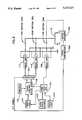
- FIG. 3is a block diagram illustrating the electronic circuit apparatus which may be used together with electromechanical translation apparatus to provide a method of operation thereof as shown in FIG. 1;
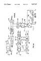
- FIGS. 4A and 4Bcomprise a block diagram illustrating in greater detail a portion of the electronic circuit apparatus shown in FIG. 3;
- FIG. 5is a timing diagram illustrating in detail the forward timing signals employed in FLY MODE operation of the electronic circuit apparatus shown in FIG. 4;
- FIG. 6is a detailed circuit illustration of the gate logic 234 used in conjunction with the electronic circuit apparatus shown in FIG. 4.
- FIGS. 1(A)-1(G)there is shown a sequence of operations of an inchworm linear motor, referenced generally 10, of a type such as disclosed in U.S. Pat. No. 3,092,084 and U.S. Pat. No. 3,092,085, the teachings of which are incorporated herein by reference.
- Motor 10comprises a driver assembly 12 which is arranged about a shaft 14, to a forward end of which (the left end as shown in the drawing) may be attached a load, such as a mirror in an optical system.
- Driver assembly 12includes forward, center and rear, typically piezoelectrically activated, cylindrical elements, referenced 16, 18 and 20, respectively, which are coupled together.
- Shaft 14additionally referenced in FIG. 2, may be moved in a forward direction relative to driver 12 by applying voltages in a predetermined sequence to the driver elements.
- driver 12has a fixed location relative to a base (not shown), this being provided by means of an element 22 protruding from center element 18 and cooperating with a corresponding portion of the base, forward element 16 is forced in a forward direction.
- shaft 14is moved axially, also in a forward direction.
- the technique of the present inventionhas important advantages for high velocity movements as compared with the prior art, it also involves certain limitations.
- the shaftis always clamped by at least one clamp. Therefore it can apply significant force, overcome relatively high frictional forces and provide high acceleration.
- FIG. 3is a block diagram illustration of apparatus for driving the linear motor in accordance with the above-described embodiment, i.e. selectably in both modes of operation.
- FIG. 3is essentially identical to FIG. 5 of U.S. Pat. No. 3,902,084, the disclosure of which is incorporated herein by reference, with the following changes:
- a motion encoder 220senses the linear motion of the shaft 14 and provides an output to a speed comparator 222, which compares the speed of shaft 14 with a predetermined threshold. Exceedance of such threshold causes comparator 222 to provide a "FLY ENABLE" signal to a selector 224, which receives output signals from clamp-unclamp pulse generator 106 and provides appropriate outputs to drive amplifiers 110 and 112 in accordance with the invention.
- the selectorselects the FLY signals and accordingly the drive amplifiers 110 and 112 are operated in accordance with the teachings of FIGS. 1(A)-1(G) and 2 hereof.
- the selector 224selects the STEP signals.
- clamp-unclamp pulse generator 106must be modified in order to operate in accordance with the present invention.
- FIGS. 4A, 4B and 5illustrate in detail the structure and timing operation of the modified clamp-unclamp pulse generator and the associated selector 224 and other circuitry of FIG. 3.
- a selector 226is associated with selector 224 and operates as described hereinbelow.
- a fly timing counter 228outputs via a decoder 230 to a flip flop 231, which outputs to a demultiplexer 232, which receives an input from gate logic 234, which is described hereinafter in detail with reference to FIG. 6.
- the remainder of the circuitry of FIGS. 4A and 4Bis identical to that appearing at FIG. 6 of U.S. Pat. No. 3,902,084.
- Selectors 224 and 226may be embodied in a TTL 74157 chip.
- the fly timing counter 228is an 8 bit up counter and may be embodied in two TTL 74161 components.
- the decoder 230may be implemented by a combination of NAND gates.
- the demultiplexer 232may be implemented by a TTL 74155 component.
- the Gate Logic 234may be implemented by a combination of NAND gates as shown in FIG. 6.
- the selector 224selects the timing signals of the two engine drive amplifiers.
- the NFWD ENG signaldrives the forward engine clamp and the NREAR ENG signal drives the backward engine clamp.
- the selector 224selects the FWD ENG and the REAR ENG signals and allows the motor to operate in its normal mode (STEP MODE). In that case, the selector 226 selects the output of delay line 138 as T 1 as it is in the original circuit described in U.S. Pat. No. 3,902,084.
- the selector 224selects the FFWD ENG (FLY FWD ENG) and FREAR ENG (FLY REAR ENG) signals and thus enables the motor to operate in the FLY MODE.
- the timing signals T0, T1 and T2do not affect the motor clamps.
- the selector 226selects T0 as T1, therefore there is only a very short pulse on T0, which is defined by the delay of delay line 140, and is intended only for resetting fly timing counter 228.
- the fly timing counter 228receives a short reset pulse when the CH1 or CL1 signals are active and receives the CLK signal from the input of Gates Circuit 122.
- the CLK signalis the same clock signal that is provided to Up-Down Counter 124.
- Counter 228counts up during rising or falling of the stair-case signal STR-V at the output of O/A 130.
- Decoder 230decodes the outputs of the fly timing counter 228 and provides a CE (Clamp Energized) signal and a CR (Clamp Release) signal.
- the CE signalis provided at the beginning of the counting (at a count of 10, for example) and the CR signal is provided at the end of the counting (at a count of 230 foir example).
- the CE signalsets the flip flop 231 and the CR signal resets it. In that way, there is obtained at the output of flip flop 231 a FCLAMP (Fast Clamp) signal which goes high in response to the CE signal and goes low at the timing of the CR signal.
- the FCLAMP signalis provided once either at the rise or the fall of the staircase signal STR-V.
- the Gate Logic 234receives the FWD-1 and REV-1 signals from flip flop 160 and the CH1 signal from flip flop 134 and produces a select signal which is supplied to demultiplexer 232.
- the select signalis changed with every rise and fall of the staircase signal according to the motor direction which is set by the FWD-1 and REV-1 signals.
- the demultiplexer 232activates the FFWD ENG signal while the staircase signal is rising and activates the FREAR ENG signal while the staircase signal is falling, producing forward motion of the motor. If the REV-1 signal is active, the demultiplexer activates the FFWD ENG signal while the staircase signal is falling and the FREAR ENG signal while the staircase signal is rising, thus producing backwards motion of the motor.
Landscapes
- General Electrical Machinery Utilizing Piezoelectricity, Electrostriction Or Magnetostriction (AREA)
Abstract
Description
Claims (21)
Applications Claiming Priority (2)
| Application Number | Priority Date | Filing Date | Title |
|---|---|---|---|
| IL87312AIL87312A (en) | 1988-08-02 | 1988-08-02 | Electromechanical translation apparatus of the inchworm linear motor type |
| IL87312 | 1988-08-02 |
Publications (1)
| Publication Number | Publication Date |
|---|---|
| US5027027Atrue US5027027A (en) | 1991-06-25 |
Family
ID=11059113
Family Applications (1)
| Application Number | Title | Priority Date | Filing Date |
|---|---|---|---|
| US07/382,853Expired - Fee RelatedUS5027027A (en) | 1988-08-02 | 1989-07-20 | Electromechanical translation apparatus |
Country Status (2)
| Country | Link |
|---|---|
| US (1) | US5027027A (en) |
| IL (1) | IL87312A (en) |
Cited By (40)
| Publication number | Priority date | Publication date | Assignee | Title |
|---|---|---|---|---|
| US5268621A (en)* | 1992-09-29 | 1993-12-07 | Wisconsin Alumni Research Foundation | Digital controller for inchworm piezoelectric translator |
| US5319257A (en)* | 1992-07-13 | 1994-06-07 | Martin Marietta Energy Systems, Inc. | Unitaxial constant velocity microactuator |
| US5332942A (en)* | 1993-06-07 | 1994-07-26 | Rennex Brian G | Inchworm actuator |
| US5378948A (en)* | 1991-08-13 | 1995-01-03 | Richter; Hans | Electroactive motor |
| US5404066A (en)* | 1991-06-21 | 1995-04-04 | Toyoda Koki Kabushiki Kaisha | Feed system |
| US5432395A (en)* | 1993-08-02 | 1995-07-11 | Bonneville Scientific Incorporated | Direct-drive field actuator motors |
| US5453653A (en)* | 1993-07-09 | 1995-09-26 | Nanomotion Ltd. | Ceramic motor |
| FR2723196A1 (en)* | 1994-07-29 | 1996-02-02 | St Louis Inst Franco Alle Rech | MICROMETRIC ACTUATOR |
| US5616980A (en)* | 1993-07-09 | 1997-04-01 | Nanomotion Ltd. | Ceramic motor |
| US5682076A (en)* | 1993-08-03 | 1997-10-28 | Nanomotion Ltd. | Ceramic disc-drive actuator |
| US5686778A (en)* | 1994-07-25 | 1997-11-11 | Nikon Corporation | Movement device utilizing electromechanical conversion elements and control method therefore |
| US5751090A (en)* | 1995-05-17 | 1998-05-12 | Burleigh Instruments Inc | Peristaltic driver apparatus |
| US5907212A (en)* | 1996-03-06 | 1999-05-25 | Minolta Co., Ltd. | Apparatus provided with electro-mechanical transducer |
| DE19853324A1 (en)* | 1998-04-18 | 1999-10-21 | Univ Ilmenau Tech | Horizontal driving gear with linear actuators |
| US6053287A (en)* | 1997-04-25 | 2000-04-25 | Invento Ag | Linear drive for transportation equipment |
| US6104125A (en)* | 1998-01-26 | 2000-08-15 | Industrial Technology Research Institute | Linear actuator |
| US6194912B1 (en) | 1999-03-11 | 2001-02-27 | Easic Corporation | Integrated circuit device |
| WO2001033646A1 (en)* | 1999-11-03 | 2001-05-10 | New Focus, Inc. | Control for piezoelectric actuator |
| US6236229B1 (en) | 1999-05-13 | 2001-05-22 | Easic Corporation | Integrated circuits which employ look up tables to provide highly efficient logic cells and logic functionalities |
| US6245634B1 (en) | 1999-10-28 | 2001-06-12 | Easic Corporation | Method for design and manufacture of semiconductors |
| US6331733B1 (en) | 1999-08-10 | 2001-12-18 | Easic Corporation | Semiconductor device |
| US6437226B2 (en) | 2000-03-07 | 2002-08-20 | Viking Technologies, Inc. | Method and system for automatically tuning a stringed instrument |
| WO2002099958A1 (en)* | 2001-06-04 | 2002-12-12 | Nanyang Technological University | Linear piezoelectric motor with self locking means |
| US6548938B2 (en) | 2000-04-18 | 2003-04-15 | Viking Technologies, L.C. | Apparatus having a pair of opposing surfaces driven by a piezoelectric actuator |
| US20030193266A1 (en)* | 2002-02-06 | 2003-10-16 | Jeff Moler | Apparatus for moving a pair of opposing surfaces in response to an electrical activation |
| US20040045148A1 (en)* | 2002-06-21 | 2004-03-11 | Jeff Moler | Uni-body piezoelectric motor |
| US6717332B2 (en) | 2000-04-18 | 2004-04-06 | Viking Technologies, L.C. | Apparatus having a support structure and actuator |
| US6759790B1 (en) | 2001-01-29 | 2004-07-06 | Viking Technologies, L.C. | Apparatus for moving folded-back arms having a pair of opposing surfaces in response to an electrical activation |
| US6836056B2 (en)* | 2000-02-04 | 2004-12-28 | Viking Technologies, L.C. | Linear motor having piezo actuators |
| US20040263025A1 (en)* | 2003-04-04 | 2004-12-30 | Jeff Moler | Apparatus and process for optimizing work from a smart material actuator product |
| WO2005067072A1 (en)* | 2004-01-08 | 2005-07-21 | Thorlabs, Inc. | Piezoelectric positioner |
| US20060197167A1 (en)* | 2005-03-03 | 2006-09-07 | Pratt & Whitney Canada Corp. | Electromagnetic actuator |
| US20070287841A1 (en)* | 2006-06-13 | 2007-12-13 | Abraham Benderly | Transesterification process for production of (meth)acrylate ester monomers |
| US20080074000A1 (en)* | 2006-03-08 | 2008-03-27 | Dynamic Structures And Materials, Llc | Spring biasing locking mechanism for step and repeat motors |
| US20090001852A1 (en)* | 2007-05-17 | 2009-01-01 | Nikon Corporation | Piezoelectric actuator, piezoelectric actuator device, lens barrel, optical device and manufacturing method thereof |
| US20090225297A1 (en)* | 2006-08-25 | 2009-09-10 | Carl Zeiss Smt Ag | Projection exposure apparatus and optical system |
| EP2209202A3 (en)* | 2001-06-12 | 2010-11-10 | Physik Instrumente (PI) GmbH & Co. KG | Method for operating a piezo linear drive with a group of piezo stack actuators |
| US20110220821A1 (en)* | 2008-11-24 | 2011-09-15 | Peter Hess | Drive Mechanism For The Movement Of An Object Along An Axis Of Motion And Micro-Valve |
| US20120161579A1 (en)* | 2010-12-28 | 2012-06-28 | Gm Global Technology Operations, Inc. | Tubular actuators utilizing active material activation |
| US20150370176A1 (en)* | 2008-07-22 | 2015-12-24 | Carl Zeiss Smt Gmbh | Actuators and microlithography projection exposure systems and methods using the same |
Citations (5)
| Publication number | Priority date | Publication date | Assignee | Title |
|---|---|---|---|---|
| US3902084A (en)* | 1974-05-30 | 1975-08-26 | Burleigh Instr | Piezoelectric electromechanical translation apparatus |
| US3902085A (en)* | 1974-11-25 | 1975-08-26 | Burleigh Instr | Electromechanical translation apparatus |
| SU752560A1 (en)* | 1978-02-08 | 1980-07-30 | Московский институт электронной техники | Piezoelectric linear step motor |
| US4422002A (en)* | 1981-08-10 | 1983-12-20 | International Business Machines Corporation | Piezo-electric travelling support |
| US4468583A (en)* | 1982-10-22 | 1984-08-28 | Hitachi, Ltd. | Piezoelectric rotary actuator |
- 1988
- 1988-08-02ILIL87312Apatent/IL87312A/ennot_activeIP Right Cessation
- 1989
- 1989-07-20USUS07/382,853patent/US5027027A/ennot_activeExpired - Fee Related
Patent Citations (5)
| Publication number | Priority date | Publication date | Assignee | Title |
|---|---|---|---|---|
| US3902084A (en)* | 1974-05-30 | 1975-08-26 | Burleigh Instr | Piezoelectric electromechanical translation apparatus |
| US3902085A (en)* | 1974-11-25 | 1975-08-26 | Burleigh Instr | Electromechanical translation apparatus |
| SU752560A1 (en)* | 1978-02-08 | 1980-07-30 | Московский институт электронной техники | Piezoelectric linear step motor |
| US4422002A (en)* | 1981-08-10 | 1983-12-20 | International Business Machines Corporation | Piezo-electric travelling support |
| US4468583A (en)* | 1982-10-22 | 1984-08-28 | Hitachi, Ltd. | Piezoelectric rotary actuator |
Non-Patent Citations (2)
| Title |
|---|
| Piezo Drive w/Coarse and Fine Adjustment, by Binnig et al., IBM Technical Disclosure Bulletin, vol. 22, No. 7, Dec. 1979, pp. 2897 2898.* |
| Piezo Drive w/Coarse and Fine Adjustment, by Binnig et al., IBM Technical Disclosure Bulletin, vol. 22, No. 7, Dec. 1979, pp. 2897-2898. |
Cited By (63)
| Publication number | Priority date | Publication date | Assignee | Title |
|---|---|---|---|---|
| US5404066A (en)* | 1991-06-21 | 1995-04-04 | Toyoda Koki Kabushiki Kaisha | Feed system |
| US5378948A (en)* | 1991-08-13 | 1995-01-03 | Richter; Hans | Electroactive motor |
| US5319257A (en)* | 1992-07-13 | 1994-06-07 | Martin Marietta Energy Systems, Inc. | Unitaxial constant velocity microactuator |
| US5268621A (en)* | 1992-09-29 | 1993-12-07 | Wisconsin Alumni Research Foundation | Digital controller for inchworm piezoelectric translator |
| US5332942A (en)* | 1993-06-07 | 1994-07-26 | Rennex Brian G | Inchworm actuator |
| US6064140A (en)* | 1993-07-09 | 2000-05-16 | Nanomotion Ltd | Ceramic motor |
| US5453653A (en)* | 1993-07-09 | 1995-09-26 | Nanomotion Ltd. | Ceramic motor |
| US5616980A (en)* | 1993-07-09 | 1997-04-01 | Nanomotion Ltd. | Ceramic motor |
| US5432395A (en)* | 1993-08-02 | 1995-07-11 | Bonneville Scientific Incorporated | Direct-drive field actuator motors |
| US5777423A (en)* | 1993-08-03 | 1998-07-07 | Nanomotion Ltd. | Ceramic motor |
| US5682076A (en)* | 1993-08-03 | 1997-10-28 | Nanomotion Ltd. | Ceramic disc-drive actuator |
| US5686778A (en)* | 1994-07-25 | 1997-11-11 | Nikon Corporation | Movement device utilizing electromechanical conversion elements and control method therefore |
| FR2723196A1 (en)* | 1994-07-29 | 1996-02-02 | St Louis Inst Franco Alle Rech | MICROMETRIC ACTUATOR |
| US5751090A (en)* | 1995-05-17 | 1998-05-12 | Burleigh Instruments Inc | Peristaltic driver apparatus |
| US5907212A (en)* | 1996-03-06 | 1999-05-25 | Minolta Co., Ltd. | Apparatus provided with electro-mechanical transducer |
| US6053287A (en)* | 1997-04-25 | 2000-04-25 | Invento Ag | Linear drive for transportation equipment |
| US6104125A (en)* | 1998-01-26 | 2000-08-15 | Industrial Technology Research Institute | Linear actuator |
| DE19853324A1 (en)* | 1998-04-18 | 1999-10-21 | Univ Ilmenau Tech | Horizontal driving gear with linear actuators |
| US6194912B1 (en) | 1999-03-11 | 2001-02-27 | Easic Corporation | Integrated circuit device |
| US6236229B1 (en) | 1999-05-13 | 2001-05-22 | Easic Corporation | Integrated circuits which employ look up tables to provide highly efficient logic cells and logic functionalities |
| US6331789B2 (en) | 1999-05-13 | 2001-12-18 | Easic Corporation | Semiconductor device |
| US6331733B1 (en) | 1999-08-10 | 2001-12-18 | Easic Corporation | Semiconductor device |
| US6476493B2 (en) | 1999-08-10 | 2002-11-05 | Easic Corp | Semiconductor device |
| US6245634B1 (en) | 1999-10-28 | 2001-06-12 | Easic Corporation | Method for design and manufacture of semiconductors |
| US6686253B2 (en) | 1999-10-28 | 2004-02-03 | Easic Corporation | Method for design and manufacture of semiconductors |
| WO2001033646A1 (en)* | 1999-11-03 | 2001-05-10 | New Focus, Inc. | Control for piezoelectric actuator |
| US6836056B2 (en)* | 2000-02-04 | 2004-12-28 | Viking Technologies, L.C. | Linear motor having piezo actuators |
| US6437226B2 (en) | 2000-03-07 | 2002-08-20 | Viking Technologies, Inc. | Method and system for automatically tuning a stringed instrument |
| US6548938B2 (en) | 2000-04-18 | 2003-04-15 | Viking Technologies, L.C. | Apparatus having a pair of opposing surfaces driven by a piezoelectric actuator |
| US20030127948A1 (en)* | 2000-04-18 | 2003-07-10 | Jeff Moler | Apparatus having a pair of opposing surfaces driven by a piezoelectric actuator |
| US6717332B2 (en) | 2000-04-18 | 2004-04-06 | Viking Technologies, L.C. | Apparatus having a support structure and actuator |
| US6737788B2 (en) | 2000-04-18 | 2004-05-18 | Viking Technologies, L.C. | Apparatus having a pair of opposing surfaces driven by a piezoelectric actuator |
| US6759790B1 (en) | 2001-01-29 | 2004-07-06 | Viking Technologies, L.C. | Apparatus for moving folded-back arms having a pair of opposing surfaces in response to an electrical activation |
| WO2002099958A1 (en)* | 2001-06-04 | 2002-12-12 | Nanyang Technological University | Linear piezoelectric motor with self locking means |
| EP2209202A3 (en)* | 2001-06-12 | 2010-11-10 | Physik Instrumente (PI) GmbH & Co. KG | Method for operating a piezo linear drive with a group of piezo stack actuators |
| US20030193266A1 (en)* | 2002-02-06 | 2003-10-16 | Jeff Moler | Apparatus for moving a pair of opposing surfaces in response to an electrical activation |
| US6975061B2 (en) | 2002-02-06 | 2005-12-13 | Viking Technologies, L.C. | Apparatus for moving a pair of opposing surfaces in response to an electrical activation |
| US6870305B2 (en) | 2002-02-06 | 2005-03-22 | Viking Technologies, L.C. | Apparatus for moving a pair of opposing surfaces in response to an electrical activation |
| US6879087B2 (en) | 2002-02-06 | 2005-04-12 | Viking Technologies, L.C. | Apparatus for moving a pair of opposing surfaces in response to an electrical activation |
| US20040045148A1 (en)* | 2002-06-21 | 2004-03-11 | Jeff Moler | Uni-body piezoelectric motor |
| US6924586B2 (en) | 2002-06-21 | 2005-08-02 | Viking Technologies, L.C. | Uni-body piezoelectric motor |
| US20040263025A1 (en)* | 2003-04-04 | 2004-12-30 | Jeff Moler | Apparatus and process for optimizing work from a smart material actuator product |
| US7368856B2 (en) | 2003-04-04 | 2008-05-06 | Parker-Hannifin Corporation | Apparatus and process for optimizing work from a smart material actuator product |
| US7564171B2 (en) | 2003-04-04 | 2009-07-21 | Parker-Hannifin Corporation | Apparatus and process for optimizing work from a smart material actuator product |
| WO2005067072A1 (en)* | 2004-01-08 | 2005-07-21 | Thorlabs, Inc. | Piezoelectric positioner |
| US20060197167A1 (en)* | 2005-03-03 | 2006-09-07 | Pratt & Whitney Canada Corp. | Electromagnetic actuator |
| US7227440B2 (en) | 2005-03-03 | 2007-06-05 | Pratt & Whitney Canada Corp. | Electromagnetic actuator |
| US20080074000A1 (en)* | 2006-03-08 | 2008-03-27 | Dynamic Structures And Materials, Llc | Spring biasing locking mechanism for step and repeat motors |
| US7471030B2 (en) | 2006-03-08 | 2008-12-30 | Dynamic Structures And Materials, Llc | Spring biasing locking mechanism for step and repeat motors |
| US20070287841A1 (en)* | 2006-06-13 | 2007-12-13 | Abraham Benderly | Transesterification process for production of (meth)acrylate ester monomers |
| US7528278B2 (en) | 2006-06-13 | 2009-05-05 | Rohm And Haas Company | Transesterification process for production of (meth)acrylate ester monomers |
| US8269948B2 (en) | 2006-08-25 | 2012-09-18 | Carl Zeiss Smt Gmbh | Projection exposure apparatus and optical system |
| US20090225297A1 (en)* | 2006-08-25 | 2009-09-10 | Carl Zeiss Smt Ag | Projection exposure apparatus and optical system |
| US9110388B2 (en) | 2006-08-25 | 2015-08-18 | Carl Zeiss Smt Gmbh | Projection exposure apparatus with multiple sets of piezoelectric elements moveable in different directions and related method |
| US20090001852A1 (en)* | 2007-05-17 | 2009-01-01 | Nikon Corporation | Piezoelectric actuator, piezoelectric actuator device, lens barrel, optical device and manufacturing method thereof |
| US8283837B2 (en)* | 2007-05-17 | 2012-10-09 | Nikon Corporation | Piezoelectric actuator, piezoelectric actuator device, lens barrel, optical device and manufacturing method thereof |
| US20150370176A1 (en)* | 2008-07-22 | 2015-12-24 | Carl Zeiss Smt Gmbh | Actuators and microlithography projection exposure systems and methods using the same |
| US9766550B2 (en)* | 2008-07-22 | 2017-09-19 | Carl Zeiss Smt Gmbh | Actuators and microlithography projection exposure systems and methods using the same |
| US8777179B2 (en)* | 2008-11-24 | 2014-07-15 | Hess Innovation Gmbh | Drive mechanism for the movement of an object along an axis of motion and micro-valve |
| US20110220821A1 (en)* | 2008-11-24 | 2011-09-15 | Peter Hess | Drive Mechanism For The Movement Of An Object Along An Axis Of Motion And Micro-Valve |
| US20120161579A1 (en)* | 2010-12-28 | 2012-06-28 | Gm Global Technology Operations, Inc. | Tubular actuators utilizing active material activation |
| US8446065B2 (en)* | 2010-12-28 | 2013-05-21 | GM Global Technology Operations LLC | Tubular actuators utilizing active material activation |
| DE102011121741B4 (en)* | 2010-12-28 | 2018-07-12 | GM Global Technology Operations LLC (n. d. Gesetzen des Staates Delaware) | Tubular actuator |
Also Published As
| Publication number | Publication date |
|---|---|
| IL87312A0 (en) | 1989-01-31 |
| IL87312A (en) | 1992-02-16 |
Similar Documents
| Publication | Publication Date | Title |
|---|---|---|
| US5027027A (en) | Electromechanical translation apparatus | |
| US3902084A (en) | Piezoelectric electromechanical translation apparatus | |
| US5917267A (en) | Linear drive mechanism using electromechanical conversion element | |
| US6476537B1 (en) | Apparatus for controlling a piezoelectric assembly of a piezo actuator coupled with a driven member | |
| US6249093B1 (en) | Drive mechanism employing electromechanical transducer, photographing lens with the drive mechanism, and its drive circuit | |
| US7567012B2 (en) | Drive unit | |
| US7271522B2 (en) | Driving device and driving method | |
| US3866533A (en) | Electrical print impression control | |
| JP3417390B2 (en) | Actuator using electromechanical transducer | |
| US7750534B2 (en) | Drive device and drive system | |
| US4423941A (en) | Device for shifting lens group | |
| US6218765B1 (en) | Driving device using an electromechanical transducer, and an apparatus having the driving device | |
| US5097161A (en) | Linear actuator | |
| US6545389B1 (en) | Driving control apparatus and driving control method | |
| US11342865B2 (en) | Method and device for actuating an electromechanical element | |
| DE3123906A1 (en) | ELECTRICALLY DRIVEN PANEL ADJUSTMENT | |
| JP2002281771A (en) | Drive mechanism using piezoelectric element | |
| US20060049716A1 (en) | Drive unit | |
| US4910789A (en) | Apparatus for controlling the adjustment rate of a lens assembly | |
| CN208143113U (en) | Control system for step-by-step movement driving device | |
| CN108448927B (en) | Control systems for stepper drives | |
| KR100809754B1 (en) | Drive | |
| JPH0870586A (en) | Driver using electromechanical converting element | |
| SU964950A1 (en) | Device for start-stop control of stopping motor | |
| JPH01187402A (en) | scanning tunneling microscope |
Legal Events
| Date | Code | Title | Description |
|---|---|---|---|
| AS | Assignment | Owner name:QUICK TECHNOLOGIES LTD., ADVANCED TECHNOLOGY CENTE Free format text:ASSIGNMENT OF ASSIGNORS INTEREST.;ASSIGNOR:OR-BACH, ZVI;REEL/FRAME:005610/0021 Effective date:19901009 Owner name:QUICK TECHNOLOGIES LTD., ADVANCED TECHNOLOGY CENTE Free format text:ASSIGNMENT OF ASSIGNORS INTEREST.;ASSIGNOR:GANOR, ZEEV;REEL/FRAME:005610/0019 Effective date:19901008 | |
| FEPP | Fee payment procedure | Free format text:PAYOR NUMBER ASSIGNED (ORIGINAL EVENT CODE: ASPN); ENTITY STATUS OF PATENT OWNER: LARGE ENTITY | |
| FPAY | Fee payment | Year of fee payment:4 | |
| AS | Assignment | Owner name:COMERICA BANK - CALIFORNIA, CALIFORNIA Free format text:SECURITY AGREEMENT;ASSIGNOR:CHIP-EXPRESS CORPORATION;REEL/FRAME:007656/0095 Effective date:19950803 | |
| FPAY | Fee payment | Year of fee payment:8 | |
| AS | Assignment | Owner name:CHIP EXPRESS CORPORATION, CALIFORNIA Free format text:REASSIGNMENT AND RELEASE OF SECURITY INTEREST;ASSIGNOR:COMERICA BANK-CALIFORNIA;REEL/FRAME:013616/0915 Effective date:20021220 | |
| REMI | Maintenance fee reminder mailed | ||
| LAPS | Lapse for failure to pay maintenance fees | ||
| STCH | Information on status: patent discontinuation | Free format text:PATENT EXPIRED DUE TO NONPAYMENT OF MAINTENANCE FEES UNDER 37 CFR 1.362 | |
| FP | Lapsed due to failure to pay maintenance fee | Effective date:20030625 |