US5026992A - Spectral ratioing technique for NDIR gas analysis using a differential temperature source - Google Patents
Spectral ratioing technique for NDIR gas analysis using a differential temperature sourceDownload PDFInfo
- Publication number
- US5026992A US5026992AUS07/403,587US40358789AUS5026992AUS 5026992 AUS5026992 AUS 5026992AUS 40358789 AUS40358789 AUS 40358789AUS 5026992 AUS5026992 AUS 5026992A
- Authority
- US
- United States
- Prior art keywords
- radiation
- gas
- sample
- wavelength
- centered
- Prior art date
- Legal status (The legal status is an assumption and is not a legal conclusion. Google has not performed a legal analysis and makes no representation as to the accuracy of the status listed.)
- Expired - Lifetime
Links
- 230000003595spectral effectEffects0.000titledescription35
- 238000000034methodMethods0.000titledescription15
- 238000004868gas analysisMethods0.000titledescription2
- 238000001745non-dispersive infrared spectroscopyMethods0.000title1
- 230000005855radiationEffects0.000claimsabstractdescription54
- 230000009977dual effectEffects0.000claimsabstractdescription27
- 238000001228spectrumMethods0.000claimsabstractdescription10
- VNWKTOKETHGBQD-UHFFFAOYSA-NmethaneChemical compoundCVNWKTOKETHGBQD-UHFFFAOYSA-N0.000claimsdescription24
- 238000012545processingMethods0.000claimsdescription5
- 239000007789gasSubstances0.000description72
- 230000009102absorptionEffects0.000description16
- 238000010521absorption reactionMethods0.000description16
- 238000005259measurementMethods0.000description11
- 230000003287optical effectEffects0.000description9
- 230000005540biological transmissionEffects0.000description7
- 230000008901benefitEffects0.000description6
- CURLTUGMZLYLDI-UHFFFAOYSA-NCarbon dioxideChemical compoundO=C=OCURLTUGMZLYLDI-UHFFFAOYSA-N0.000description5
- 238000001514detection methodMethods0.000description5
- 229910002092carbon dioxideInorganic materials0.000description4
- 238000010586diagramMethods0.000description4
- 238000009826distributionMethods0.000description4
- 230000008859changeEffects0.000description3
- 239000000203mixtureSubstances0.000description3
- 238000005457optimizationMethods0.000description3
- 239000000779smokeSubstances0.000description3
- 238000013459approachMethods0.000description2
- 230000001419dependent effectEffects0.000description2
- 238000013461designMethods0.000description2
- 238000006073displacement reactionMethods0.000description2
- 239000000463materialSubstances0.000description2
- 230000000737periodic effectEffects0.000description2
- YBNMDCCMCLUHBL-UHFFFAOYSA-N(2,5-dioxopyrrolidin-1-yl) 4-pyren-1-ylbutanoateChemical compoundC=1C=C(C2=C34)C=CC3=CC=CC4=CC=C2C=1CCCC(=O)ON1C(=O)CCC1=OYBNMDCCMCLUHBL-UHFFFAOYSA-N0.000description1
- 235000011449RosaNutrition0.000description1
- 238000000862absorption spectrumMethods0.000description1
- 230000003321amplificationEffects0.000description1
- 238000009412basement excavationMethods0.000description1
- 239000001569carbon dioxideSubstances0.000description1
- 238000002485combustion reactionMethods0.000description1
- 230000001143conditioned effectEffects0.000description1
- 238000011161developmentMethods0.000description1
- 210000005069earsAnatomy0.000description1
- 230000000694effectsEffects0.000description1
- 238000000691measurement methodMethods0.000description1
- 238000003199nucleic acid amplification methodMethods0.000description1
- 230000008520organizationEffects0.000description1
- 230000004044responseEffects0.000description1
- 230000035945sensitivityEffects0.000description1
- 239000007787solidSubstances0.000description1
- 230000001360synchronised effectEffects0.000description1
- 238000012546transferMethods0.000description1
Images

Classifications
- G—PHYSICS
- G08—SIGNALLING
- G08B—SIGNALLING OR CALLING SYSTEMS; ORDER TELEGRAPHS; ALARM SYSTEMS
- G08B29/00—Checking or monitoring of signalling or alarm systems; Prevention or correction of operating errors, e.g. preventing unauthorised operation
- G08B29/18—Prevention or correction of operating errors
- G08B29/20—Calibration, including self-calibrating arrangements
- G—PHYSICS
- G01—MEASURING; TESTING
- G01N—INVESTIGATING OR ANALYSING MATERIALS BY DETERMINING THEIR CHEMICAL OR PHYSICAL PROPERTIES
- G01N21/00—Investigating or analysing materials by the use of optical means, i.e. using sub-millimetre waves, infrared, visible or ultraviolet light
- G01N21/17—Systems in which incident light is modified in accordance with the properties of the material investigated
- G01N21/25—Colour; Spectral properties, i.e. comparison of effect of material on the light at two or more different wavelengths or wavelength bands
- G01N21/255—Details, e.g. use of specially adapted sources, lighting or optical systems
- G—PHYSICS
- G01—MEASURING; TESTING
- G01N—INVESTIGATING OR ANALYSING MATERIALS BY DETERMINING THEIR CHEMICAL OR PHYSICAL PROPERTIES
- G01N21/00—Investigating or analysing materials by the use of optical means, i.e. using sub-millimetre waves, infrared, visible or ultraviolet light
- G01N21/17—Systems in which incident light is modified in accordance with the properties of the material investigated
- G01N21/25—Colour; Spectral properties, i.e. comparison of effect of material on the light at two or more different wavelengths or wavelength bands
- G01N21/31—Investigating relative effect of material at wavelengths characteristic of specific elements or molecules, e.g. atomic absorption spectrometry
- G01N21/35—Investigating relative effect of material at wavelengths characteristic of specific elements or molecules, e.g. atomic absorption spectrometry using infrared light
- G01N21/3504—Investigating relative effect of material at wavelengths characteristic of specific elements or molecules, e.g. atomic absorption spectrometry using infrared light for analysing gases, e.g. multi-gas analysis
- G—PHYSICS
- G08—SIGNALLING
- G08B—SIGNALLING OR CALLING SYSTEMS; ORDER TELEGRAPHS; ALARM SYSTEMS
- G08B17/00—Fire alarms; Alarms responsive to explosion
- G08B17/10—Actuation by presence of smoke or gases, e.g. automatic alarm devices for analysing flowing fluid materials by the use of optical means
- G08B17/117—Actuation by presence of smoke or gases, e.g. automatic alarm devices for analysing flowing fluid materials by the use of optical means by using a detection device for specific gases, e.g. combustion products, produced by the fire
- G—PHYSICS
- G01—MEASURING; TESTING
- G01J—MEASUREMENT OF INTENSITY, VELOCITY, SPECTRAL CONTENT, POLARISATION, PHASE OR PULSE CHARACTERISTICS OF INFRARED, VISIBLE OR ULTRAVIOLET LIGHT; COLORIMETRY; RADIATION PYROMETRY
- G01J1/00—Photometry, e.g. photographic exposure meter
- G01J1/10—Photometry, e.g. photographic exposure meter by comparison with reference light or electric value provisionally void
- G01J1/16—Photometry, e.g. photographic exposure meter by comparison with reference light or electric value provisionally void using electric radiation detectors
- G01J2001/161—Ratio method, i.e. Im/Ir
- G—PHYSICS
- G01—MEASURING; TESTING
- G01J—MEASUREMENT OF INTENSITY, VELOCITY, SPECTRAL CONTENT, POLARISATION, PHASE OR PULSE CHARACTERISTICS OF INFRARED, VISIBLE OR ULTRAVIOLET LIGHT; COLORIMETRY; RADIATION PYROMETRY
- G01J1/00—Photometry, e.g. photographic exposure meter
- G01J1/10—Photometry, e.g. photographic exposure meter by comparison with reference light or electric value provisionally void
- G01J1/16—Photometry, e.g. photographic exposure meter by comparison with reference light or electric value provisionally void using electric radiation detectors
- G01J1/18—Photometry, e.g. photographic exposure meter by comparison with reference light or electric value provisionally void using electric radiation detectors using comparison with a reference electric value
- G01J2001/182—Photometry, e.g. photographic exposure meter by comparison with reference light or electric value provisionally void using electric radiation detectors using comparison with a reference electric value with SH sample and hold circuits
- G—PHYSICS
- G01—MEASURING; TESTING
- G01N—INVESTIGATING OR ANALYSING MATERIALS BY DETERMINING THEIR CHEMICAL OR PHYSICAL PROPERTIES
- G01N21/00—Investigating or analysing materials by the use of optical means, i.e. using sub-millimetre waves, infrared, visible or ultraviolet light
- G01N21/17—Systems in which incident light is modified in accordance with the properties of the material investigated
- G01N21/25—Colour; Spectral properties, i.e. comparison of effect of material on the light at two or more different wavelengths or wavelength bands
- G01N21/31—Investigating relative effect of material at wavelengths characteristic of specific elements or molecules, e.g. atomic absorption spectrometry
- G01N21/314—Investigating relative effect of material at wavelengths characteristic of specific elements or molecules, e.g. atomic absorption spectrometry with comparison of measurements at specific and non-specific wavelengths
- G—PHYSICS
- G01—MEASURING; TESTING
- G01N—INVESTIGATING OR ANALYSING MATERIALS BY DETERMINING THEIR CHEMICAL OR PHYSICAL PROPERTIES
- G01N21/00—Investigating or analysing materials by the use of optical means, i.e. using sub-millimetre waves, infrared, visible or ultraviolet light
- G01N21/17—Systems in which incident light is modified in accordance with the properties of the material investigated
- G01N21/59—Transmissivity
- G01N21/61—Non-dispersive gas analysers
- G—PHYSICS
- G01—MEASURING; TESTING
- G01N—INVESTIGATING OR ANALYSING MATERIALS BY DETERMINING THEIR CHEMICAL OR PHYSICAL PROPERTIES
- G01N2201/00—Features of devices classified in G01N21/00
- G01N2201/02—Mechanical
- G01N2201/022—Casings
- G01N2201/0228—Moulded parts
- G—PHYSICS
- G01—MEASURING; TESTING
- G01N—INVESTIGATING OR ANALYSING MATERIALS BY DETERMINING THEIR CHEMICAL OR PHYSICAL PROPERTIES
- G01N2201/00—Features of devices classified in G01N21/00
- G01N2201/06—Illumination; Optics
- G01N2201/061—Sources
- G01N2201/06186—Resistance heated; wire sources; lamelle sources
- G—PHYSICS
- G01—MEASURING; TESTING
- G01N—INVESTIGATING OR ANALYSING MATERIALS BY DETERMINING THEIR CHEMICAL OR PHYSICAL PROPERTIES
- G01N2201/00—Features of devices classified in G01N21/00
- G01N2201/06—Illumination; Optics
- G01N2201/069—Supply of sources
- G01N2201/0696—Pulsed
Definitions
- the present inventionis in the field of non-dispersive infrared (NDIR) gas analyzers of a type typically used to measure the concentrations of unwanted or combustible gases so that an alarm can be given when their concentration approaches a harmful or dangerous level. More specifically, the present invention relates to a comparatively small apparatus having no moving parts and capable of measuring the concentration of one or more specified components in a mixture of gases.
- NDIRnon-dispersive infrared
- the NDIR technique utilizing the characteristic absorption bands of gases in the infraredhas been widely used in the gas analyzer industry for the detection of these gases.
- Such gas analyzersutilize the principle that various gases exhibit substantial absorption at specific wavelengths in the infrared radiation spectrum.
- the term "non-dispersive" as used hereinrefers to the apparatus used, typically a narrow-band optical or infrared transmission filter instead of a dispersive element such as a prism or diffraction grating, for isolating for purposes of measurement the radiation in a particular wavelength band that normally coincides with a strong absorption band in the absorption spectrum of a gas to be measured.
- the NDIR techniqueoffers a number of distinct advantages over previous methods that use the principle of heat transfer based upon radiation absorption by certain gases. These advantages include speed of response, measurement stability, greater sensitivity and simpler implementation.
- NDIR gas analyzeris shown and described in U.S. Pat. No. 3,811,776 by Blau, Jr. It incorporates (in addition to the infrared source, sample chamber, narrow band-pass filter and detector) a reference cell (a gas cell containing the gas of interest, e.g., CO 2 ) and an identical cell evacuated or filled with a gas that is transparent at the wavelength used (4.26 microns for CO 2 ) such as N 2 . These two cells alternately are moved into and out of the radiation beam.
- a reference cella gas cell containing the gas of interest, e.g., CO 2
- a gas that is transparent at the wavelength used (4.26 microns for CO 2 )such as N 2
- the alternate introduction of the absorbing and nonabsorbing cells into the radiation beamcreates, respectively, a reference detector signal and a sample detector signal whose ratio is used to determine the gas concentration in the sample chamber.
- the Blau configurationtakes advantage of the principle of nonlinear absorption by the gas to be measured (as discussed in U.S. Pat. No. 4,578,762 by Wong) in order to create the reference and sample signals.
- this particular sensorcan detect a dangerous level of the gas much sooner than the current setup in which a relatively bulky methane analyzer is normally located many feet behind the working miners. Furthermore, such a helmet-mounted methane gas sensor allows the alarm to be placed inside the helmet and close to the miner's ears thereby avoiding the tragic possibility that the alarm from a more remote methane analyzer might be drowned out by the machine noises in the mine.
- Fire sensors in use today in almost all public buildings and private dwellingsare in essence smoke detectors as they only detect the smoke resulting from a fire. These sensors are compact and low cost, but they have been known to generate frequent and annoying false alarms. It is generally believed that the detection of an elevated level of carbon dioxide gas as a result of the combustion process taking place in any fire is a better alternative to the smoke detector in terms of false alarms. However, implementation of such a fire sensor using NDIR techniques presently available is far too complex and costly to serve as a viable alternative.
- Yamada in U.S. Pat. No. 4,605,855further proposed an NDIR gas analyzer with a compact cell structure but retaining a mechanical chopper.
- Kebabian in U.S. Pat. No. 4,605,313proposed a new approach using an absorptive film on the surface of a thermal detector as a means to detect gases of interest.
- the behavior of the absorptive film specific only to the gas of interestdirectly modifies the detector output thus creating a unique signal.
- the referenceis derived by using a chopper to detect a gas which does not affect the behavior of the absorptive film, thus generating a different signal at the same detector.
- the present inventortakes advantage of recent technological advances in infrared components.
- One areais the infrared source.
- the latest available device in this areais the so-called electrically modulatable infrared microsource which is, in essence, a small thick film resistor pad made out of special material capable of being heated and cooled at relatively high rate (up to 100 Hz, typically). This is achieved via standard I 2 R pulsing using a square voltage waveform.
- Infrared micro-sources composed of a thick film of resistive materialare available from Dynatech Electro-Optics Corporation of San Luis Obispo, Calif., and from Novametrix of Seattle, Wash.
- Micro-sources using a heated filamentare available from Chicago Miniature Lamp Works of Chicago, Ill., and from Gilway Technical Lamp Co. of Woburn, Mass.
- the present inventionuses a differential temperature source capable of alternating between two stable emission temperatures T 1 and T 2 where it is assumed that T 2 >T 1 .
- a differential temperature sourcecapable of alternating between two stable emission temperatures T 1 and T 2 where it is assumed that T 2 >T 1 .
- Such an operating conditionis achieved by pulsing the source with two periodic square voltage waveforms having amplitudes V 1 and V 2 with V 2 >V 1 , where V 1 and V 2 correspond to source temperatures T 1 and T 2 respectively.
- the sourceemits under these conditions radiations of two different spectral contents according to Planck's radiation law, namely e(T 1 ).
- L mis the wavelength measured in microns at which the maximum spectral radiant emittance occurs and T is the source temperature in °K.
- T 2is the source temperature in °K.
- the radiation emanating from the filterwill further be modified by the latter according to the spectral positions of the two pass-bands and the source temperature T.
- the spectral radiation output after the dual pass-band filteris respectively R bbL (T 1 ).[F(L 1 )+F(L 2 )] and R bbL (T 2 ).[F(L 1 )+F(L 2 )] where F(L) is the spectral transmission function for the pass-band filter at center wavelength L.
- the gas measurement systemis completed by placing in line after the dual pass-band filter a sample chamber followed by an infrared detector.
- L 2coincide spectrally with the absorption band of a gas whose concentration we wish to measure and L 1 spectrally at a position where no appreciable absorption takes place for all the commonly encountered gases including the one to be measured and further define a spectral ratio R s to be
- A, B 1 (T 1 ,L 1 ) and B 2 (T 2 ,L 1 )are constants at a given source temperature pair (T 1 ,T 2 ) independent of the amount of the gas of interest present in the sample chamber and C 1 (T 1 ,L 2 ) and C 2 (T 2 ,L 2 ) vary with the amount of the gas in question in the sample chamber.
- the manner in which the two C functions vary with the amount of gas present in the sample chamberdepends strongly upon the choice of the source differential temperatures T 1 and T 2 .
- the spectral ratio R s defined abovecan be used to correlate the amount of gas present in the sample chamber which has an absorption band at wavelength L 2 provided that the reference wavelength L 1 is properly chosen and the temperature pair (T 1 ,T 2 ) of the differential temperature source is correctly optimized for maximum signal.
- the preferred embodiment of the present inventioncomprises a differential temperature infrared source followed by a dual pass-band interference filter, a sample chamber and an infrared detector.
- One of the pass-bands of the filtercoincides with a suitable absorption band of the gas to be measured and the other pass-band is chosen to lie at a spectral position where there is no appreciable absorption by any of the commonly encountered gases, including the one to be measured.
- the operating temperatures of the differential temperature infrared sourceare individually optimized for the particular gas to be measured.
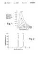
- FIG. 1is a graph showing the spectral radiant emittance of a blackbody at temperatures 500°-900° K.
- FIG. 2is a graph showing the spectral transmission curve for a dual pass-band filter used in the preferred embodiment
- FIG. 3is a graph showing the spectral radiant emittance of the differential temperature infrared source at the operating temperatures of T 1 and T 2 convoluted with the spectral transmission curve of the dual band-pass filter of the preferred embodiment;
- FIG. 4is a diagram showing the relative positions of the electrical and optical components in a preferred embodiment of the invention.
- FIG. 5is a diagram showing the relative positions of the electrical and optical components in an alternative embodiment of the invention.
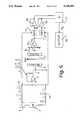
- FIG. 6is an electrical block diagram showing the interconnections of the optical and electronic components in the preferred embodiment of the invention.
- FIG. 1shows the spectral radiant emittance of a blackbody source at temperatures T ranging from 500° K. to 900° K.
- the infrared sourceis normally maintained at a constant temperature and thus its spectral radiant emittance is typically represented by one of the curves in FIG. 1 dependent upon its absolute temperature.
- a differential temperature source as used in the present inventioncapable of alternating between two stable temperatures T 1 and T 2 (T 2 >T 1 by assumption), will assume two such curves in FIG. 1.
- T 1 and T 2T 2 >T 1 by assumption
- a differential temperature sourcegenerates two different spectral radiant emittances at two alternating time intervals by assuming two different temperatures.
- the subsequent outputs emerging from the filterwill have been modified by the spectral transmission functions of the filter pass bands.
- the amount of radiation at the center wavelengths of the respective pass-bandswill change as the differential temperature source alternates between its two temperature states.
- a dual pass-band filter 6is placed in front of a differential temperature source 5 so as to intercept a substantial fraction of its Lambertian distributed (blackbody) radiation.
- lenses and mirrorsare used to capture a larger fraction of the radiation and to form it into a beam that passes through the sample chamber.
- An infrared detector 9such as a pyroelectric detector or PbSe photoconductor is placed a short distance away on the opposite side of the filter 6 from the source.
- Such a detectoris packaged in a standard TO-5 can 8 whose hermetically sealed window 8a forms together with the filter 6 the sample chamber 7 through which gases of interest to be measured may pass. Since the detector collects a significant portion of the radiation that has passed through the dual pass-band filter, the amount of radiation reaching it can be represented quantitatively as follows:
- the constants A 1 and A 2account for the spectral responsivity of the detector and the overall optical efficiency of the system and are independent of temperatures T 1 and T 2 .
- R bbL (T)is Planck's spectral radiant emittance function at the temperature T in °K.
- F(L)is the spectral transmission function of the band-pass filter centered at wavelength L.
- a spectral ratio R sis defined as follows: ##EQU1## where ##EQU2## If we now choose the value of L 2 to coincide with an appropriate absorption band of a gas selected for measurement and the value of L 1 such that there are no appreciable absorptions at that wavelength for all commonly encountered gases including the gas of interest, then the spectral ratio R s can be used to determine the amount of the gas of interest in the sample chamber of a system, such as that depicted in FIG. 4. The reason is as follows. When there is no gas of interest in the sample chamber the ratio R s reduces to a value r.A where r is only a function of T 1 and T 2 .
- B 1 and B 2remain constant as there is no absorption at the wavelength L 1 , while C 1 and C 2 will change according to the concentration of the gas in the sample chamber. Furthermore, the amount of change will be different dependent upon whether the differential temperature source is at temperature T 1 or T 2 .
- R scan be calibrated to the amount of the gas of interest in the sample chamber for a given set of T 1 and T 2 used by the differential temperature source.
- Ris a known function of T 1 , T 2 , L 1 and L 2 .
- the sourcehas the spectral distribution of a blackbody, which distribution is well known.
- the actual spectral distribution of the sourcecan be measured in advance by well known techniques.
- Ris a known function of T 1 , T 2 , L 1 and L 2 , and this opens up the possibility of optimizing R as a function of the variables, for a particular gas of interest.
- Ris almost certain not to equal 1.00, although theoretically that could result if the blackbody peaks corresponding to T 1 and T 2 were deliberately chosen to lie at certain specific locations on opposite sides of L 2 . Barring that exceptional case, R will have a value different from 1.00 and the method of the present invention will be viable.
- optimization of R with respect to T 1 , T 2 , L 1 and L 2may be desirable to increase the accuracy of the measurement.
- the optimizationcan be carried out by mathematical calculations exclusively, if desired, because the functional relationships are known.
- the optimizationcan be carried out experimentally by systematically varying T 1 , T 2 , and L 1 .
- L 2is chosen to coincide with the chosen absorption band of the gas to be detected or measured.
- L 1 ⁇ L 2 and L 1is chosen to coincide with a wavelength at which none of the gases present in the sample chamber absorb.
- Ris calculated for various combinations of T and T 2 , using the known spectral distributions and the combination yielding the minimum value of R is the combination that is optimum.
- the concentration of the gas to be detectedis inferred from the spectral ratio R as defined above, in other embodiments other variables than R may be used.
- Rspectral ratio
- a difference in the detected radiation levels or a difference in the logarithms of the detected radiation levelsare used instead of R in other embodiments.
- the present inventionis concerned with a combination of elements that produce the desired difference in detected radiation levels, and the specific functional relation by which these levels are related to the concentration is incidental, but not trivial.
- the componentsare arranged as in FIG. 5.
- the radiationpasses through the dual pass band filter 2 after traversing the sample chamber 6.
- the equations developed aboveare equally applicable to this embodiment.
- a square wave voltage generator 1is used in conjunction with a phase shifter 2 and amplifier 3 to generate a train of voltage pulses with alternately high and low square voltages.
- This periodic voltage waveform 4is applied to infrared source 5 to render it a differential temperature source. Radiation emanating from source 5 passes through the dual pass-band filter 6 which also serves as the entrance window for the sample chamber 7.
- the exit window of the sample chamber 7is the hermetically sealed window of a TO-5 can 8 which houses an infrared detector 9.
- the detector 9collects the radiation emerging from the filter 6 after it has passed through the sample chamber 7 and produces a signal in relation to the intensity of the collected radiation.
- the signalis conditioned by preamplifier 10 before being sampled by two sample-and-hold circuits 11 and 12.
- S/H circuits 11 and 12are respectively synchronized and controlled by the two phase-shifted square waveforms 13 and 14 generated by the square wave generator 1 for detecting the peak voltage values corresonding to the two temperature states of the differential temperature source 6.
- the two voltage values sampled by S/H circuits 11 and 12are applied to an analog divider circuit 17 to obtain the spectral ratio R s .
- the output of the analog divider 17is applied to a display device 18 for calibration and measurement output.
- T 1 , T 2 , L 1 , and L 2are optimized to be 523° K., 723° K., 2.20 microns, and 3.40 microns respectively.
- Table 1shows the calculated values of the spectral ratio R s as a function of methane gas concentration for a sample path length of 6 mm.
- Table 1shows the calculated values of the spectral ratio R s as a function of methane gas concentration for a sample path length of 6 mm.
- the present inventionworks well for methane gas for the set of system parameters chosen.
- the present inventionworks equally well for other gases such as CO 2 , CO, etc., but each gas requires a different optimized set of system parameters (T 1 , T 2 , L 1 , and L 2 ).
- a key feature of the inventionis the combination of a dual pass band filter with a differential temperature source.
Landscapes
- Physics & Mathematics (AREA)
- General Physics & Mathematics (AREA)
- Spectroscopy & Molecular Physics (AREA)
- Analytical Chemistry (AREA)
- Chemical & Material Sciences (AREA)
- General Health & Medical Sciences (AREA)
- Health & Medical Sciences (AREA)
- Life Sciences & Earth Sciences (AREA)
- Biochemistry (AREA)
- Immunology (AREA)
- Pathology (AREA)
- Business, Economics & Management (AREA)
- Emergency Management (AREA)
- Engineering & Computer Science (AREA)
- Computer Security & Cryptography (AREA)
- Investigating Or Analysing Materials By Optical Means (AREA)
Abstract
Description
L.sub.m.T=constant=2,897.8 micron-°K.
R.sub.s =A. R.sub.bbL ((T.sub.1).[F(L.sub.1)+F(L.sub.2)]/R.sub.bbL (T.sub.2).[F(L.sub.1)+F(L.sub.2)]
R.sub.s =A. [B.sub.1 (T.sub.1,L.sub.1)+C.sub.1 (T.sub.1,L.sub.2)]/[B.sub.2 (T.sub.2,L.sub.1) +C.sub.2 (T.sub.2,L.sub.2)]
For source temperature T.sub.1 : A.sub.1.R.sub.bbL (T.sub.1)[F(L.sub.1)+F(L.sub.2)]
For source temperature T.sub.2 : A.sub.2.R.sub.bbL (T.sub.2)[F(L.sub.1)+F(L.sub.2)]
TABLE I ______________________________________ Methane Concentration (Vol. %) R.sub.s (Normalized) ______________________________________ 0 1.000 1 1.010 2 1.020 3 1.030 4 1.042 5 1.069 10 1.291 ______________________________________
Claims (6)
Priority Applications (5)
| Application Number | Priority Date | Filing Date | Title |
|---|---|---|---|
| US07/403,587US5026992A (en) | 1989-09-06 | 1989-09-06 | Spectral ratioing technique for NDIR gas analysis using a differential temperature source |
| US07/503,215US5103096A (en) | 1989-09-06 | 1990-04-02 | Rapid fire detector |
| US07/583,234US5079422A (en) | 1989-09-06 | 1990-09-13 | Fire detection system using spatially cooperative multi-sensor input technique |
| US07/851,869US5341214A (en) | 1989-09-06 | 1992-03-16 | NDIR gas analysis using spectral ratioing technique |
| US07/874,394US5369397A (en) | 1989-09-06 | 1992-04-27 | Adaptive fire detector |
Applications Claiming Priority (2)
| Application Number | Priority Date | Filing Date | Title |
|---|---|---|---|
| US07/403,587US5026992A (en) | 1989-09-06 | 1989-09-06 | Spectral ratioing technique for NDIR gas analysis using a differential temperature source |
| CA002101082ACA2101082C (en) | 1990-04-02 | 1991-11-25 | Gas sample chamber |
Related Child Applications (1)
| Application Number | Title | Priority Date | Filing Date |
|---|---|---|---|
| US07/503,215Continuation-In-PartUS5103096A (en) | 1989-09-06 | 1990-04-02 | Rapid fire detector |
Publications (1)
| Publication Number | Publication Date |
|---|---|
| US5026992Atrue US5026992A (en) | 1991-06-25 |
Family
ID=25676405
Family Applications (1)
| Application Number | Title | Priority Date | Filing Date |
|---|---|---|---|
| US07/403,587Expired - LifetimeUS5026992A (en) | 1989-09-06 | 1989-09-06 | Spectral ratioing technique for NDIR gas analysis using a differential temperature source |
Country Status (1)
| Country | Link |
|---|---|
| US (1) | US5026992A (en) |
Cited By (52)
| Publication number | Priority date | Publication date | Assignee | Title |
|---|---|---|---|---|
| US5079422A (en)* | 1989-09-06 | 1992-01-07 | Gaztech Corporation | Fire detection system using spatially cooperative multi-sensor input technique |
| EP0544962A1 (en)* | 1991-12-04 | 1993-06-09 | Bertin & Cie | Method and apparatus for the remote optical detection of a gas in an observed region of space |
| US5394934A (en)* | 1994-04-15 | 1995-03-07 | American Standard Inc. | Indoor air quality sensor and method |
| WO1995013528A1 (en)* | 1993-11-12 | 1995-05-18 | Saphir | Device for detecting gases by infrared absorption |
| US5453620A (en)* | 1994-08-12 | 1995-09-26 | Texas Instruments Incorporated | Nondispersive infrared gas analyzer and gas sample chamber used therein |
| US5475222A (en)* | 1994-12-05 | 1995-12-12 | Detector Electronics Corporation | Ruggedized gas detector |
| EP0709659A3 (en)* | 1994-10-31 | 1997-01-08 | Valtion Teknillinen | Spectrometer |
| US5650624A (en)* | 1995-04-13 | 1997-07-22 | Engelhard Sensor Technologies, Inc. | Passive infrared analysis gas sensor |
| US5721430A (en)* | 1995-04-13 | 1998-02-24 | Engelhard Sensor Technologies Inc. | Passive and active infrared analysis gas sensors and applicable multichannel detector assembles |
| EP0837326A1 (en)* | 1996-09-27 | 1998-04-22 | Hitachi, Ltd. | Absorptivity detecting apparatus, chromatographic apparatus, method of detecting absorptivity and method of chromatography |
| US5767776A (en)* | 1996-01-29 | 1998-06-16 | Engelhard Sensor Technologies, Inc. | Fire detector |
| US5798700A (en)* | 1993-06-14 | 1998-08-25 | Engelhard Sensor Technologies, Inc. | False alarm resistant fire detector with improved performance |
| US5886348A (en)* | 1997-02-14 | 1999-03-23 | American Intell-Sensors Corporation | Non-dispersive infrared gas analyzer with interfering gas correction |
| WO1999035481A1 (en) | 1998-01-06 | 1999-07-15 | Engelhard Sensor Technologies, Inc. | A method for detecting venting of a combustion appliance within an improper space |
| US5969604A (en)* | 1997-04-29 | 1999-10-19 | Pittway Corporation | System and method of adjusting smoothing |
| US6037592A (en)* | 1997-02-14 | 2000-03-14 | Underground Systems, Inc. | System for measuring gases dissolved in a liquid |
| US6107925A (en)* | 1993-06-14 | 2000-08-22 | Edwards Systems Technology, Inc. | Method for dynamically adjusting criteria for detecting fire through smoke concentration |
| US6155160A (en)* | 1998-06-04 | 2000-12-05 | Hochbrueckner; Kenneth | Propane detector system |
| US6222456B1 (en) | 1998-10-01 | 2001-04-24 | Pittway Corporation | Detector with variable sample rate |
| US6229439B1 (en) | 1998-07-22 | 2001-05-08 | Pittway Corporation | System and method of filtering |
| US6469303B1 (en) | 2000-05-17 | 2002-10-22 | Rae Systems, Inc. | Non-dispersive infrared gas sensor |
| US20030160174A1 (en)* | 2002-01-17 | 2003-08-28 | Michael Grant | Method and apparatus for real-time monitoring of furnace flue gases |
| US20070029488A1 (en)* | 2005-08-05 | 2007-02-08 | Wong Jacob Y | Simple multi-channel NDIR gas sensors |
| US20070029487A1 (en)* | 2005-08-04 | 2007-02-08 | Wong Jacob Y | Ultra low cost NDIR gas sensors |
| WO2006127049A3 (en)* | 2004-12-29 | 2007-03-01 | Nasa | System and method for determining gas optical density changes in a non-linear measurement regime |
| WO2007064370A3 (en)* | 2005-08-04 | 2007-11-15 | Airware Inc | Ultra low cost ndir gas sensors |
| WO2008090261A1 (en)* | 2007-01-26 | 2008-07-31 | Valtion Teknillinen Tutkimuskeskus | A spectrometer and a method for controlling the spectrometer |
| US20080212100A1 (en)* | 2006-11-27 | 2008-09-04 | Nano-Proprietary, Inc. | Sono-Photonic Gas Sensor |
| WO2008141956A1 (en)* | 2007-05-24 | 2008-11-27 | Robert Bosch Gmbh | Method and device for gas analysis |
| US20110042570A1 (en)* | 2009-08-21 | 2011-02-24 | Airware, Inc. | Absorption Biased NDIR Gas Sensing Methodology |
| US8866085B1 (en)* | 2012-11-12 | 2014-10-21 | Airware, Inc | Differential temperature source NDIR gas sensing methodology |
| JP2015137863A (en)* | 2014-01-20 | 2015-07-30 | パナソニックIpマネジメント株式会社 | Infrared gas sensor |
| US9523636B2 (en) | 2012-12-28 | 2016-12-20 | Halliburton Energy Services, Inc. | Pulse width modulation of continuum sources for determination of chemical composition |
| US20180026173A1 (en)* | 2016-07-20 | 2018-01-25 | Tokin Corporation | Pyroelectric infrared sensor device |
| WO2018149799A1 (en) | 2017-02-14 | 2018-08-23 | Elichens | Method for estimating the intensity of a wave emitted by an emitting source |
| WO2018162848A1 (en) | 2017-03-10 | 2018-09-13 | Elichens | Optical gas sensor |
| WO2018229239A1 (en) | 2017-06-15 | 2018-12-20 | Elichens | Method for estimating a quantity of a gaseous species |
| CN109507140A (en)* | 2018-10-16 | 2019-03-22 | 武汉四方光电科技有限公司 | A kind of high-precision infrared gas sensor and analysis method for gases |
| WO2019081838A1 (en) | 2017-10-23 | 2019-05-02 | Elichens | Compact gas sensor |
| WO2019150053A1 (en) | 2018-02-05 | 2019-08-08 | Elichens | Method for analysing a gas by means of double illumination |
| FR3089009A1 (en) | 2018-11-27 | 2020-05-29 | Elichens | Gas sensor with a pulse light source |
| WO2020216809A1 (en) | 2019-04-25 | 2020-10-29 | Elichens | Compact gas sensor |
| WO2020234404A1 (en) | 2019-05-23 | 2020-11-26 | Elichens | Device for emitting and controlling infrared light and gas sensor using such a device |
| WO2021023576A1 (en) | 2019-08-06 | 2021-02-11 | Elichens | Method for analysing a gas using an optical sensor |
| DE102021111431A1 (en) | 2020-06-29 | 2021-12-30 | Dräger Safety AG & Co. KGaA | Surveillance system |
| WO2022074169A1 (en) | 2020-10-10 | 2022-04-14 | Elichens | Optimised infrared light source for a gas sensor, and manufacturing method thereof |
| FR3119021A1 (en) | 2021-01-21 | 2022-07-22 | Elichens | Method for calibrating a gas sensor and method for measuring a gas implementing the calibration |
| FR3121751A1 (en) | 2021-04-13 | 2022-10-14 | Elichens | Gas sensor calibration process |
| FR3124264A1 (en) | 2021-06-22 | 2022-12-23 | Elichens | Method for estimating a concentration of a gaseous species from a signal emitted by a gas sensor. |
| FR3145210A1 (en) | 2023-01-24 | 2024-07-26 | Elichens | Compact gas sensor with simple design |
| US12292429B2 (en) | 2020-06-29 | 2025-05-06 | Dräger Safety AG & Co. KGaA | Monitoring system |
| US12442758B2 (en) | 2019-08-06 | 2025-10-14 | Elichens | Method for analysing a gas using an optical sensor |
Citations (15)
| Publication number | Priority date | Publication date | Assignee | Title |
|---|---|---|---|---|
| US3793525A (en)* | 1973-01-02 | 1974-02-19 | Philco Ford Corp | Dual cell non-dispersive gas analyzer |
| US3811776A (en)* | 1973-02-26 | 1974-05-21 | Environmental Res & Tech | Gas analyzer |
| US4233513A (en)* | 1978-10-05 | 1980-11-11 | Andros Incorporated | Gas analyzer |
| US4499379A (en)* | 1982-03-09 | 1985-02-12 | Horiba, Ltd. | Infrared radiation gas analyzer |
| US4500207A (en)* | 1981-11-14 | 1985-02-19 | Ferranti, Plc | Non-dispersive optical determination of gas concentration |
| US4501968A (en)* | 1982-03-09 | 1985-02-26 | Horiba, Ltd. | Infrared radiation gas analyzer |
| US4567366A (en)* | 1982-09-25 | 1986-01-28 | Showa Denko Kabushiki Kaisha | Method and apparatus for measuring methane concentration in gas |
| US4578762A (en)* | 1983-07-01 | 1986-03-25 | Tri-Med Inc. | Self-calibrating carbon dioxide analyzer |
| US4605313A (en)* | 1985-04-10 | 1986-08-12 | Environmental Research & Technology, Inc. | Infrared detector for NDIR gas analysis |
| US4605855A (en)* | 1983-08-30 | 1986-08-12 | Horiba, Ltd. | Gas analyzer with compact cell structure |
| US4647777A (en)* | 1985-05-31 | 1987-03-03 | Ametrek, Inc. | Selective gas detector |
| US4662755A (en)* | 1984-04-10 | 1987-05-05 | Horiba, Ltd. | Gas analyzer with means for varying angle of incidence of light on interference filter |
| US4694173A (en)* | 1985-10-09 | 1987-09-15 | Hibshman Corporation | Nondispersive gas analyzer having no moving parts |
| US4709150A (en)* | 1986-03-18 | 1987-11-24 | Burough Irvin G | Method and apparatus for detecting gas |
| WO1989003028A1 (en)* | 1987-09-22 | 1989-04-06 | The Victoria University Of Manchester | Gas detection method and apparatus |
- 1989
- 1989-09-06USUS07/403,587patent/US5026992A/ennot_activeExpired - Lifetime
Patent Citations (15)
| Publication number | Priority date | Publication date | Assignee | Title |
|---|---|---|---|---|
| US3793525A (en)* | 1973-01-02 | 1974-02-19 | Philco Ford Corp | Dual cell non-dispersive gas analyzer |
| US3811776A (en)* | 1973-02-26 | 1974-05-21 | Environmental Res & Tech | Gas analyzer |
| US4233513A (en)* | 1978-10-05 | 1980-11-11 | Andros Incorporated | Gas analyzer |
| US4500207A (en)* | 1981-11-14 | 1985-02-19 | Ferranti, Plc | Non-dispersive optical determination of gas concentration |
| US4499379A (en)* | 1982-03-09 | 1985-02-12 | Horiba, Ltd. | Infrared radiation gas analyzer |
| US4501968A (en)* | 1982-03-09 | 1985-02-26 | Horiba, Ltd. | Infrared radiation gas analyzer |
| US4567366A (en)* | 1982-09-25 | 1986-01-28 | Showa Denko Kabushiki Kaisha | Method and apparatus for measuring methane concentration in gas |
| US4578762A (en)* | 1983-07-01 | 1986-03-25 | Tri-Med Inc. | Self-calibrating carbon dioxide analyzer |
| US4605855A (en)* | 1983-08-30 | 1986-08-12 | Horiba, Ltd. | Gas analyzer with compact cell structure |
| US4662755A (en)* | 1984-04-10 | 1987-05-05 | Horiba, Ltd. | Gas analyzer with means for varying angle of incidence of light on interference filter |
| US4605313A (en)* | 1985-04-10 | 1986-08-12 | Environmental Research & Technology, Inc. | Infrared detector for NDIR gas analysis |
| US4647777A (en)* | 1985-05-31 | 1987-03-03 | Ametrek, Inc. | Selective gas detector |
| US4694173A (en)* | 1985-10-09 | 1987-09-15 | Hibshman Corporation | Nondispersive gas analyzer having no moving parts |
| US4709150A (en)* | 1986-03-18 | 1987-11-24 | Burough Irvin G | Method and apparatus for detecting gas |
| WO1989003028A1 (en)* | 1987-09-22 | 1989-04-06 | The Victoria University Of Manchester | Gas detection method and apparatus |
Cited By (84)
| Publication number | Priority date | Publication date | Assignee | Title |
|---|---|---|---|---|
| US5079422A (en)* | 1989-09-06 | 1992-01-07 | Gaztech Corporation | Fire detection system using spatially cooperative multi-sensor input technique |
| EP0544962A1 (en)* | 1991-12-04 | 1993-06-09 | Bertin & Cie | Method and apparatus for the remote optical detection of a gas in an observed region of space |
| US5306913A (en)* | 1991-12-04 | 1994-04-26 | Bertin & Cie | Method and apparatus for remote optical detection of a gas present in an observed volume |
| US5798700A (en)* | 1993-06-14 | 1998-08-25 | Engelhard Sensor Technologies, Inc. | False alarm resistant fire detector with improved performance |
| US6107925A (en)* | 1993-06-14 | 2000-08-22 | Edwards Systems Technology, Inc. | Method for dynamically adjusting criteria for detecting fire through smoke concentration |
| WO1995013528A1 (en)* | 1993-11-12 | 1995-05-18 | Saphir | Device for detecting gases by infrared absorption |
| FR2712390A1 (en)* | 1993-11-12 | 1995-05-19 | Saphir | Gas detection device by infrared absorption. |
| US5608219A (en)* | 1993-11-12 | 1997-03-04 | Saphir | Device for detecting gas by infrared absorption |
| US5394934A (en)* | 1994-04-15 | 1995-03-07 | American Standard Inc. | Indoor air quality sensor and method |
| US5453620A (en)* | 1994-08-12 | 1995-09-26 | Texas Instruments Incorporated | Nondispersive infrared gas analyzer and gas sample chamber used therein |
| EP0709659A3 (en)* | 1994-10-31 | 1997-01-08 | Valtion Teknillinen | Spectrometer |
| US5475222A (en)* | 1994-12-05 | 1995-12-12 | Detector Electronics Corporation | Ruggedized gas detector |
| US5650624A (en)* | 1995-04-13 | 1997-07-22 | Engelhard Sensor Technologies, Inc. | Passive infrared analysis gas sensor |
| US5721430A (en)* | 1995-04-13 | 1998-02-24 | Engelhard Sensor Technologies Inc. | Passive and active infrared analysis gas sensors and applicable multichannel detector assembles |
| US5767776A (en)* | 1996-01-29 | 1998-06-16 | Engelhard Sensor Technologies, Inc. | Fire detector |
| EP0837326A1 (en)* | 1996-09-27 | 1998-04-22 | Hitachi, Ltd. | Absorptivity detecting apparatus, chromatographic apparatus, method of detecting absorptivity and method of chromatography |
| US5892581A (en)* | 1996-09-27 | 1999-04-06 | Hitachi, Ltd. | Absorptivity detecting apparatus, chromatographic apparatus, method of detecting absorptivity and method of chromatography |
| US6037592A (en)* | 1997-02-14 | 2000-03-14 | Underground Systems, Inc. | System for measuring gases dissolved in a liquid |
| US5886348A (en)* | 1997-02-14 | 1999-03-23 | American Intell-Sensors Corporation | Non-dispersive infrared gas analyzer with interfering gas correction |
| US5969604A (en)* | 1997-04-29 | 1999-10-19 | Pittway Corporation | System and method of adjusting smoothing |
| WO1999035481A1 (en) | 1998-01-06 | 1999-07-15 | Engelhard Sensor Technologies, Inc. | A method for detecting venting of a combustion appliance within an improper space |
| US6250133B1 (en)* | 1998-01-06 | 2001-06-26 | Edwards Systems Technology, Inc. | Method for detecting venting of a combustion appliance within an improper space |
| US6155160A (en)* | 1998-06-04 | 2000-12-05 | Hochbrueckner; Kenneth | Propane detector system |
| US6229439B1 (en) | 1998-07-22 | 2001-05-08 | Pittway Corporation | System and method of filtering |
| US6222456B1 (en) | 1998-10-01 | 2001-04-24 | Pittway Corporation | Detector with variable sample rate |
| US6469303B1 (en) | 2000-05-17 | 2002-10-22 | Rae Systems, Inc. | Non-dispersive infrared gas sensor |
| US7022992B2 (en)* | 2002-01-17 | 2006-04-04 | American Air Liquide, Inc. | Method and apparatus for real-time monitoring of furnace flue gases |
| US20030160174A1 (en)* | 2002-01-17 | 2003-08-28 | Michael Grant | Method and apparatus for real-time monitoring of furnace flue gases |
| WO2006127049A3 (en)* | 2004-12-29 | 2007-03-01 | Nasa | System and method for determining gas optical density changes in a non-linear measurement regime |
| US7358489B2 (en) | 2005-08-04 | 2008-04-15 | Airware, Inc. | Ultra low cost NDIR gas sensors |
| US20070029487A1 (en)* | 2005-08-04 | 2007-02-08 | Wong Jacob Y | Ultra low cost NDIR gas sensors |
| WO2007064370A3 (en)* | 2005-08-04 | 2007-11-15 | Airware Inc | Ultra low cost ndir gas sensors |
| US7329870B2 (en)* | 2005-08-05 | 2008-02-12 | Airware, Inc. | Simple multi-channel NDIR gas sensors |
| US20070029488A1 (en)* | 2005-08-05 | 2007-02-08 | Wong Jacob Y | Simple multi-channel NDIR gas sensors |
| US20080212100A1 (en)* | 2006-11-27 | 2008-09-04 | Nano-Proprietary, Inc. | Sono-Photonic Gas Sensor |
| US7782462B2 (en) | 2006-11-27 | 2010-08-24 | Applied Nanotech Holdings, Inc. | Sono-photonic gas sensor |
| WO2008090261A1 (en)* | 2007-01-26 | 2008-07-31 | Valtion Teknillinen Tutkimuskeskus | A spectrometer and a method for controlling the spectrometer |
| US20100097613A1 (en)* | 2007-01-26 | 2010-04-22 | Valtion Teknillinen Tutkimuskeskus | Spectrometer and a method for controlling the spectrometer |
| US8233147B2 (en) | 2007-01-26 | 2012-07-31 | Valtion Teknillinen Tutkimuskeskus | Spectrometer and a method for controlling the spectrometer |
| WO2008141956A1 (en)* | 2007-05-24 | 2008-11-27 | Robert Bosch Gmbh | Method and device for gas analysis |
| US20100140477A1 (en)* | 2007-05-24 | 2010-06-10 | Alexander Graf | Method and device for gas analysis |
| US8143581B2 (en) | 2009-08-21 | 2012-03-27 | Jacob Y Wong | Absorption biased NDIR gas sensing methodology |
| US20110042570A1 (en)* | 2009-08-21 | 2011-02-24 | Airware, Inc. | Absorption Biased NDIR Gas Sensing Methodology |
| US8866085B1 (en)* | 2012-11-12 | 2014-10-21 | Airware, Inc | Differential temperature source NDIR gas sensing methodology |
| US9523636B2 (en) | 2012-12-28 | 2016-12-20 | Halliburton Energy Services, Inc. | Pulse width modulation of continuum sources for determination of chemical composition |
| EP2914988A4 (en)* | 2012-12-28 | 2017-01-11 | Halliburton Energy Services, Inc. | Pulse width modulation of continuum sources for determination of chemical composition |
| US9778172B2 (en) | 2012-12-28 | 2017-10-03 | Halliburton Energy Services, Inc. | Pulse width modulation of continuum sources for determination of chemical composition |
| JP2015137863A (en)* | 2014-01-20 | 2015-07-30 | パナソニックIpマネジメント株式会社 | Infrared gas sensor |
| US20180026173A1 (en)* | 2016-07-20 | 2018-01-25 | Tokin Corporation | Pyroelectric infrared sensor device |
| US11101422B2 (en)* | 2016-07-20 | 2021-08-24 | Tokin Corporation | Pyroelectric infrared sensor device |
| WO2018149799A1 (en) | 2017-02-14 | 2018-08-23 | Elichens | Method for estimating the intensity of a wave emitted by an emitting source |
| WO2018162848A1 (en) | 2017-03-10 | 2018-09-13 | Elichens | Optical gas sensor |
| WO2018229239A1 (en) | 2017-06-15 | 2018-12-20 | Elichens | Method for estimating a quantity of a gaseous species |
| US11041801B2 (en) | 2017-06-15 | 2021-06-22 | Elichens | Method for estimating a quantity of a gaseous species |
| WO2019081838A1 (en) | 2017-10-23 | 2019-05-02 | Elichens | Compact gas sensor |
| WO2019150053A1 (en) | 2018-02-05 | 2019-08-08 | Elichens | Method for analysing a gas by means of double illumination |
| US11448590B2 (en) | 2018-02-05 | 2022-09-20 | Elichens | Method for analysing a gas by means of double illumination |
| CN109507140A (en)* | 2018-10-16 | 2019-03-22 | 武汉四方光电科技有限公司 | A kind of high-precision infrared gas sensor and analysis method for gases |
| WO2020109708A1 (en) | 2018-11-27 | 2020-06-04 | Elichens | Gas sensor comprising a pulsed light source |
| US12287284B2 (en) | 2018-11-27 | 2025-04-29 | Elichens | Gas sensor comprising a pulsed light source |
| FR3089009A1 (en) | 2018-11-27 | 2020-05-29 | Elichens | Gas sensor with a pulse light source |
| WO2020216809A1 (en) | 2019-04-25 | 2020-10-29 | Elichens | Compact gas sensor |
| FR3095517A1 (en) | 2019-04-25 | 2020-10-30 | Elichens | Compact gas sensor |
| US11921031B2 (en) | 2019-04-25 | 2024-03-05 | Elichens | Compact gas sensor |
| WO2020234404A1 (en) | 2019-05-23 | 2020-11-26 | Elichens | Device for emitting and controlling infrared light and gas sensor using such a device |
| FR3096461A1 (en) | 2019-05-23 | 2020-11-27 | Elichens | Device for emitting and controlling infra-red light and gas sensor using such a device |
| US12066377B2 (en) | 2019-05-23 | 2024-08-20 | Elichens | Device for emitting and controlling infrared light and gas sensor using such a device |
| FR3099828A1 (en) | 2019-08-06 | 2021-02-12 | Elichens | Method for analyzing a gas by an optical sensor |
| WO2021023576A1 (en) | 2019-08-06 | 2021-02-11 | Elichens | Method for analysing a gas using an optical sensor |
| US12442758B2 (en) | 2019-08-06 | 2025-10-14 | Elichens | Method for analysing a gas using an optical sensor |
| WO2022002555A1 (en) | 2020-06-29 | 2022-01-06 | Dräger Safety AG & Co. KGaA | Monitoring system |
| US12292429B2 (en) | 2020-06-29 | 2025-05-06 | Dräger Safety AG & Co. KGaA | Monitoring system |
| DE102021111431A1 (en) | 2020-06-29 | 2021-12-30 | Dräger Safety AG & Co. KGaA | Surveillance system |
| WO2022074169A1 (en) | 2020-10-10 | 2022-04-14 | Elichens | Optimised infrared light source for a gas sensor, and manufacturing method thereof |
| FR3115104A1 (en) | 2020-10-10 | 2022-04-15 | Elichens | Gas sensor optimized light emitting device and method of manufacture |
| US12372457B2 (en) | 2020-10-10 | 2025-07-29 | Elichens | Optimized infrared light source for a gas sensor, and manufacturing method thereof |
| FR3119021A1 (en) | 2021-01-21 | 2022-07-22 | Elichens | Method for calibrating a gas sensor and method for measuring a gas implementing the calibration |
| WO2022157208A1 (en) | 2021-01-21 | 2022-07-28 | Elichens | Method for calibrating a gas sensor and method for measuring a gas using the calibration |
| US12313530B2 (en) | 2021-01-21 | 2025-05-27 | Elichens | Method for calibrating a gas sensor and method for measuring a gas using the calibration |
| FR3121751A1 (en) | 2021-04-13 | 2022-10-14 | Elichens | Gas sensor calibration process |
| WO2022268821A1 (en) | 2021-06-22 | 2022-12-29 | Elichens | Method and device for estimating a concentration of a gaseous species based on a signal emitted by a gas sensor |
| FR3124264A1 (en) | 2021-06-22 | 2022-12-23 | Elichens | Method for estimating a concentration of a gaseous species from a signal emitted by a gas sensor. |
| EP4407300A1 (en) | 2023-01-24 | 2024-07-31 | Elichens | Compact gas sensor of simple design |
| FR3145210A1 (en) | 2023-01-24 | 2024-07-26 | Elichens | Compact gas sensor with simple design |
Similar Documents
| Publication | Publication Date | Title |
|---|---|---|
| US5026992A (en) | Spectral ratioing technique for NDIR gas analysis using a differential temperature source | |
| US2930893A (en) | Long path infrared detection of atmospheric contaminants | |
| US4160163A (en) | Flame sensing system | |
| US5339155A (en) | Optical wavelength modulated long-path gas monitoring apparatus | |
| US4296324A (en) | Dual spectrum infrared fire sensor | |
| US4126396A (en) | Device for the non-dispersive optical determination of the concentration of gas and smoke components | |
| CA1237177A (en) | Apparatus and method for remote sensing of gases, vapours or aerosols | |
| US3869613A (en) | Infrared gas analyzers | |
| US3488491A (en) | Filter techniques for gas analyzers employing an inert gas to pressure broaden the absorption spectrum of gas being detected | |
| NO162436C (en) | MEASURING HEAD FOR AN INFRARED ABSORPTION GAS DETECTOR. | |
| JPH07280730A (en) | Method and apparatus for determining gas concentration | |
| NO167342B (en) | DUAL CHANNEL FIRE SENSOR. | |
| US3723731A (en) | Absorption spectroscopy | |
| JPS6312938A (en) | Gas analyzer and gas analysis method | |
| US4692622A (en) | Infrared analyzer | |
| US3725702A (en) | Infrared gas analyzer | |
| US3171027A (en) | Infrared atmospheric contamination detector system with the detector interrupted at a sub-harmonic frequency of the source | |
| GB927340A (en) | A continuously self-calibrating differential detection system | |
| US4891518A (en) | Apparatus for detecting a plurality of gases | |
| US4468561A (en) | Nondispersive infrared gas analyzer | |
| JPS59208445A (en) | Method and device for measuring absorptive component quantity of sample | |
| US3851176A (en) | Plural gas non-dispersive infrared analyzer | |
| US4605313A (en) | Infrared detector for NDIR gas analysis | |
| NL7908629A (en) | DEVICE FOR DETECTING COMPONENTS IN GASES BY RADIATION. | |
| JPS61194332A (en) | Method and device for measuring gas concentration |
Legal Events
| Date | Code | Title | Description |
|---|---|---|---|
| AS | Assignment | Owner name:EVIONICS, INC., CALIFORNIA Free format text:ASSIGNMENT OF ASSIGNORS INTEREST.;ASSIGNOR:WONG, JACOB Y.;REEL/FRAME:005119/0557 Effective date:19890902 | |
| AS | Assignment | Owner name:WONG, JACOB Y., CALIFORNIA Free format text:ASSIGNMENT OF ASSIGNORS INTEREST.;ASSIGNOR:EVIONICS, INC.;REEL/FRAME:005401/0502 Effective date:19900717 | |
| AS | Assignment | Owner name:GAZTECH CORPORATION, CALIFORNIA Free format text:ASSIGNMENT OF ASSIGNORS INTEREST.;ASSIGNOR:WONG, JACOB Y.;REEL/FRAME:005415/0238 Effective date:19900717 | |
| STCF | Information on status: patent grant | Free format text:PATENTED CASE | |
| FEPP | Fee payment procedure | Free format text:PAYOR NUMBER ASSIGNED (ORIGINAL EVENT CODE: ASPN); ENTITY STATUS OF PATENT OWNER: LARGE ENTITY Free format text:PAT HLDR NO LONGER CLAIMS SMALL ENT STAT AS SMALL BUSINESS (ORIGINAL EVENT CODE: LSM2); ENTITY STATUS OF PATENT OWNER: LARGE ENTITY | |
| FPAY | Fee payment | Year of fee payment:4 | |
| AS | Assignment | Owner name:ENGELHARD SENSOR TECHNOLOGIES, INC, CALIFORNIA Free format text:ASSIGNMENT OF ASSIGNORS INTEREST;ASSIGNOR:TELAIRE SYSTEMS, INC;REEL/FRAME:008209/0114 Effective date:19960920 | |
| FEPP | Fee payment procedure | Free format text:PAYER NUMBER DE-ASSIGNED (ORIGINAL EVENT CODE: RMPN); ENTITY STATUS OF PATENT OWNER: LARGE ENTITY Free format text:PAYOR NUMBER ASSIGNED (ORIGINAL EVENT CODE: ASPN); ENTITY STATUS OF PATENT OWNER: LARGE ENTITY | |
| FPAY | Fee payment | Year of fee payment:8 | |
| REMI | Maintenance fee reminder mailed | ||
| AS | Assignment | Owner name:EDWARDS SYSTEMS TECHNOLOGY, INC., CONNECTICUT Free format text:ASSIGNMENT OF ASSIGNORS INTEREST;ASSIGNORS:ENGELHARD CORPORATION;ENGELHARD SENSOR TECHNOLOGIES;REEL/FRAME:010742/0069 Effective date:20000208 | |
| AS | Assignment | Owner name:TELAIRE SYSTEMS, INC. (DE CORP), CALIFORNIA Free format text:CHANGE OF NAME;ASSIGNOR:GAZTECH INTERNATIONAL CORPORATION;REEL/FRAME:011245/0809 Effective date:19930902 | |
| AS | Assignment | Owner name:EDWARDS SYTEMS TECHNOLOGY, INC., CONNECTICUT Free format text:ASSIGNMENT OF ASSIGNORS INTEREST;ASSIGNORS:ENGELHARD SENSOR TECHNOLOGIES, INC.;ENGELHARD CORPORATION;REEL/FRAME:011369/0402 Effective date:20000208 | |
| FPAY | Fee payment | Year of fee payment:12 |