US5026383A - Apparatus for in-situ cutting of valves within veins and method therefor - Google Patents
Apparatus for in-situ cutting of valves within veins and method thereforDownload PDFInfo
- Publication number
- US5026383A US5026383AUS07/366,427US36642789AUS5026383AUS 5026383 AUS5026383 AUS 5026383AUS 36642789 AUS36642789 AUS 36642789AUS 5026383 AUS5026383 AUS 5026383A
- Authority
- US
- United States
- Prior art keywords
- cutting
- catheter
- vein
- blades
- valve
- Prior art date
- Legal status (The legal status is an assumption and is not a legal conclusion. Google has not performed a legal analysis and makes no representation as to the accuracy of the status listed.)
- Expired - Fee Related
Links
Images

Classifications
- A—HUMAN NECESSITIES
- A61—MEDICAL OR VETERINARY SCIENCE; HYGIENE
- A61B—DIAGNOSIS; SURGERY; IDENTIFICATION
- A61B17/00—Surgical instruments, devices or methods
- A61B17/32—Surgical cutting instruments
- A61B17/3205—Excision instruments
- A61B17/3207—Atherectomy devices working by cutting or abrading; Similar devices specially adapted for non-vascular obstructions
- A61B17/32075—Pullback cutting; combined forward and pullback cutting, e.g. with cutters at both sides of the plaque
- A—HUMAN NECESSITIES
- A61—MEDICAL OR VETERINARY SCIENCE; HYGIENE
- A61B—DIAGNOSIS; SURGERY; IDENTIFICATION
- A61B17/00—Surgical instruments, devices or methods
- A61B17/22—Implements for squeezing-off ulcers or the like on inner organs of the body; Implements for scraping-out cavities of body organs, e.g. bones; for invasive removal or destruction of calculus using mechanical vibrations; for removing obstructions in blood vessels, not otherwise provided for
- A61B2017/22097—Valve removal in veins
Definitions
- This inventionrelates to a method and apparatus for cutting valves within veins, specifically, for cutting out vein valves during vascular reconstructive surgery.
- itconstitutes an apparatus for cutting the valves in a vein in a procedure known as in-situ saphenous vein bypass.
- In-situ saphenous vein bypassis a procedure which utilizes the saphenous vein in the human leg, which normally returns blood from the ankle upwardly through the leg, to take over the function of the main artery in the leg after it has become too occluded or otherwise impaired to transport the flow of blood required of it.
- saphenous veinWhen the saphenous vein is to be used to take over the function of the artery, it becomes necessary to cut open a series of one-way valves in the vein which, in normal functioning, prevent reverse flow of the blood.
- valve strippershave been developed over the years for performing this function. Some of these valve strippers have used a valve cutter which is passed through the vein in a direction reverse to the normal direction of blood flow to sever the valves. Examples of such valve cutters include the LaMaitre valvulotome made by Vascutech, Inc. of Massachusetts; the Hall vein stripper made by Cabot Ltd. of High Wycombe, England and the Leather valve cutter made by American V. Mueller of Chicago, Ill. These valve strippers operate blind, that is to say they are passed through the vein without direct observation inside the vein of the positioning of the cutters as they operate. While these devices can perform quite satisfactorily in the hands of an experienced cardiovascular surgeon operating on a vein which does not have complications, blind incision of the valves has serious risks.
- the Chin patentdiscloses a pulling catheter which is inserted into the vein near the ankle, and is passed in the normal direction of blood flow through the saphenous vein and the vein valves until its tip emerges through an exit opening created in the vein.
- a cutting catheterwhich carries a group of four cutting fingers at its end, is attached to the pulling catheter which is then pulled reversely through the vein to cause the cutting fingers to cut through the valves.
- Each cutting fingeris V-shaped with its apex facing the vein sidewall.
- a fiber optic scopeis mounted in the cutting catheter for viewing through its advanced, open end.
- a wirepasses through the length of the pulling catheter and has a V-folded hook at leading end.
- a button at the opposite end of the wirecan be pushed inwardly of the pulling catheter to project the hook to grip a flexible loop attached to the adjacent end of the cutting catheter and then retracted to secure the loop against release.
- a retractably mounted sheathsurrounds the cutting catheter. The sheath is advanced along the cutting catheter to enclose the cutting fingers during passage through the vein and is withdrawn from the fingers to expose them only during the cutting of a valve.
- the Chin deviceis generally satisfactory for the purposes for which it is intended, there are respects in which need exists for improvement.
- the button for moving the wire hook and the loop on the second catheterare separated by the length of the patient's leg during the performance of the operation. This separation complicates the manipulation of the parts necessary to achieve connection of the catheters.
- the manipulation back and forth of the slidable sheathalso adds a level of complication in operating the apparatus that it would be desirable to eliminate.
- the sheathcan impair the field of view of the optic scope making it more difficult to observe and avoid side branches.
- the present inventionconstitutes a method and apparatus for in-situ cutting of valves within veins designed to solve the problems that have been discussed.
- the inventionuses two catheters, each of sufficient flexibility to follow the contour of the vein when passed through it. Entry and exit openings are made in the vein, with the exit opening spaced downstream of the entry opening in the normal direction of blood flood.
- One of the catheters, the cutting cathetercarries cutting blades.
- the other, pulling catheteris introduced to the vein through the entry opening, passed through the vein until it emerges through the exit opening, and is then connected to the cutting catheter.
- the connectionis effected by a filament.
- the filamentwhich is secured to the cutting catheter, carries a detent which is releasably engagable with a retainer immovably secured to the pulling catheter.
- the retainerhas a keyhole-shaped slot having a wide head opening which accepts the detent and filament and a narrower slit into which the filament passes with the detent being trapped so that the catheters are connected.
- the cutting bladeswhich are diametrically spaced, are sized and shaped to engage and cut through the valve cusps when they are aligned with them and pulled reversely through the valve.
- Each cutter bladehas a rounded nose portion which, if the cutter blade glances against the side of the vein wall, steers the cutter in the direction of the interior of the vein to reduce the risk of gouging the vein wall and damaging the endothelial lining.
- the use of the cutterproceeds under observation through a fiber optic viewing scope.
- the scopeis positioned within the bladed catheter for viewing the blades and the adjacent regions of the vein and valves during the cutter's progress reversely through the vein.
- the catheter carrying the cutting bladescan be rotated, if necessary, to align the cutting blades with the cusps of the valve so that the valve is cut open when the cutter is pulled reversely through it. Due to the use of cutters which are alignable to engage the valve cusps under the observation available from the viewing scope and contoured to minimize gouging the vein wall, the present invention eliminates any need for the complexities of movable structure to sheath and unsheath the blades.
- the viewing scopeis detachably mounted in the cutting catheter which is disposable.
- the mountingincludes a plurality of spacing members concentrically secured around the scope, spaced along its length, and providing channels through which saline can be selectively passed through the catheter.
- the salineis used to irrigate the field of view of the scope and back pressure the valves to close them. After an operation, the relatively expensive scope can be withdrawn from the cutting catheter for repeated use, allowing the disposable catheter to be disposed of.
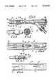
- FIG. 1is an external view of a cutting catheter and a pulling catheter, forming parts of an apparatus constructed in accordance with the preferred embodiment of the invention.
- FIGS. 2a-2cillustrate a sequence of steps in performing the preferred embodiment of the method of the present invention in which (i) the pulling catheter shown in FIG. 1 is introduced into the vein and passed through it in the normal direction of blood flow (FIG. 2a); (ii) after the pulling catheter has emerged through an exit opening in the vein, the cutting catheter is connected to it by a filament (FIG. 2b), and; (iii) the catheters are pulled reversely through the vein to cause the cutter blades to cut through the vein valves (FIG. 2c);
- FIG. 3shows a fragmentary cross-sectional view of the cutting catheter shown in FIG. 1;
- FIG. 4is a cross-sectional end view of the cutting catheter shown in FIG. 3 taken along the lines 4--4 therein, illustrating a spacer for supporting a fiber optic scope within the cutting catheter;
- FIG. 5is a side view of a cutting blade projecting from the end of the cutting catheter and a filament attached to the cutting catheter;
- FIG. 6constitutes a side view of the cutting catheter and the pulling catheter joined together by the filament, with the cutting catheter approaching a pair of valve cusps;
- FIG. 7is an enlarged view showing the connection of the filament to the pulling catheter, taken along the lines 7--7 in FIG. 6;
- FIG. 8is a cross-sectional view showing the position of the cutting blades in phantom line to illustrate how they are shaped to avoid gouging into the side wall of the vein in the event of a glancing contact with it.
- FIG. 1An apparatus for in-situ cutting of valves within the saphenous vein, constructed in accordance with a preferred embodiment of the apparatus, is shown in FIG. 1. This procedure is performed to cut through the one-way valves in the saphenous vein to function as an artery to convey blood down the leg.
- the apparatusincludes a cutting catheter 2, so called because it has a head 6 with cutter blades 8 mounted in its leading end (FIGS. 1 and 3).
- Valve cuttingis performed by moving the cutting catheter 2 through a vein 10 (FIG. 2c) in a direction reverse to the normal direction in which blood flows through the vein so that the blades 8 cut through the one way leaflet valves 12 within the vein.
- Each valvehas two valve cusps 14 with diametrically spaced regions of attachment to the vein. The cusps extend across the vein into contact with each other to act as one way valves, opening when blood flows in the normal direction along the vein, from ankle upwards, and closing to prevent reverse blood flow.
- the anatomy of the valves in the saphenous veinis illustrated, for example, in the "Atlas of Vascular Surgery" by Zarins and Gewertz (published by Churchill Livingstone 1989) at page 165.
- a pulling catheter 16is connected to it and pulled reversely through the vein (FIG. 2c). Both catheters 2 and 16 are sufficiently flexible to follow the contour of the saphenous vein.
- the catheters 2 and 16are model ov.246 catheters made by Nobles-Lai Engineering, Inc., Santa Ana, Calif. in two sizes having external diameters of 2.5 and 2.0 mm. and an internal diameter of 2.0 and 1.5 mm, respectively, fabricated from polyvinyl chloride and polyethylene.
- other catheters sized to fit within the saphenous vein and possessing comparable qualities of stiffness, flexibility and medical inertnessmay be used.
- FIGS. 2a-2cOf particular interest to the present invention is the procedure by which the catheters are introduced into the vein, are connected, and are then manipulated to cut through the valves. This procedure is illustrated in FIGS. 2a-2c.
- the pulling catheter 16is inserted into the saphenous vein through an entry opening (not shown) made in the vein by the surgeon in the region of the patient's ankle.
- the catheter 16is then passed upwardly through the saphenous vein, as shown in FIG. 2a, in the normal direction of blood flow, opening and passing through the valves 12 as it travels. Its advancing end eventually emerges through an exit opening (not shown) made by the surgeon downstream of the entry opening, in the region of the patient's groin, as shown in FIG. 2b.
- the length of the pulling catheter 16is sufficient that at, its lower end, it is still extending through the entry opening.
- the cathetersare then connected by a linkage, after which pulling force is applied to the end of the pulling catheter still outside the entry opening to pull the cutting catheter 2 reversely through the vein so that the blades 8 can cut through the valves.
- the detentis releasably engaged with a retainer 26 that is immovably mounted in the end of the pulling catheter 16.
- the retainer 22is a cylindrical tube adhesively secured in the end of the pulling catheter 16 which it distends.
- the tubehas a cylindrical side wall and a flat end wall facing outwardly of the catheter.
- the slot 24has a head opening 26 sized to closely receive the ball 20 and a relatively narrower slit 28 which extends through the cylinder side wall sized to closely receive the filament.
- the slitalso extends through the end wall to its center.
- the surgeonsimply has to press the ball 20 through the opening 26 in the sidewall of the cylindrical retainer 22 and then slide the filament along the slit 28 to the closed end 30, thereby trapping the detent within the retainer. Once secured, it requires deliberate and careful manipulation later to release the detent. It is virtually impossible for the filament to become inadvertently detached from the retainer during in-situ movements of the catheters through the vein.
- the just described structure for linking the two catheters togetheroffers significant advantages. The connection can be easily and swiftly made by the surgeon since the only moving part is the detent which slides in the keyhole-shaped slot and this requires little manipulation.
- the fiber optic viewing scope 30mounted in the cutting catheter 2, illustrated in FIG. 3.
- the scopehas a field of view through the open ends of the catheter 2 and the head 6 and through an unobstructed space between the cutting blades 8.
- the fiber optic scope 30is of the lighted type manufactured by Edwards Laboratories of Santa Ana, Calif.
- the scopehas a central monolithic viewing strand enclosed by illuminating strands.
- the scopeincludes a collecting lens 32 at its leading end and, at its opposite end, the scope is secured to a suitable viewing device such as an eyepiece or video viewer (not shown).
- the viewing scopepermits the surgeon to make observations as the cutter blades pass through the saphenous vein to avoid damage to the endothelial lining and to detect side branches 31 so that they are not incised by the cutters. Other regions or structures within the vein, which should be avoided by the cutter blades to prevent injury, can also be detected in time to avoid incision by observation through the scope.
- a spacer 34mounts the end of the scope 30 concentrically within the head 6 for viewing through the end of the catheter through an unobstructed space between the cutting blades 8.
- the spacer 34has an annular body 36 snugly encircling the fiber optic scope 30 in contact with the lens 32.
- the salineis introduced through a Y-junction fitting 40, (FIG. 3) connected to the trailing end of the catheter 2.
- a Y-junction fitting 40(FIG. 3) connected to the trailing end of the catheter 2.
- an end cap 42At the axial end of the Y-junction there is an end cap 42 having a central opening which includes a recessed seat for an O-ring 46.
- the O-ringsupports, and provides a liquid tight seal around, the fiber optic scope 30 which passes through the seal and extends to the eyepiece.
- the salineis injected to irrigate blood away from the viewing area so that the adjacent regions of the vein may be clearly observed.
- the injected salineis also used to apply reverse pressure to the cusps of each valve 12 to close it, before the cutting blades cut through the valve
- the cutter headis a cylindrical one-piece structure molded from a plastic capable of having sharp edges formed in it, such as high density injection molded nylon.
- the cutting headis adhesively secured into the open end of the cutting catheter 2 which it distends (FIG. 3).
- the cutter bladesare sized appropriately for the vein which is to be the subject of the valve cutting procedure.
- Each cutter blade 8, in plan,is generally parabola shaped (FIG. 5). In profile, each blade 8 has a base region 50 (FIG.
- the bladeshave sharp interior edges 53 which are configures to define a slot 54 extending transversely through the cutting head.
- the slotresembles a U at its apex with the sides of the U flaring outwardly to intersect the tips of the cutting blades.
- the inward curve on the outer surface on the nose 52reduces the risk of damage to the endothelial lining of the vein sidewall in the event of glancing contact between the blade and the vein.
- a glancing contactis meant one in which the blade moves against the vein side wall at angle of less than about 15°. Impacts at greater angles of misalignment are less likely because of the observations made through the scope and because the generally parallel alignment of the vein, the catheters and the filament urge the cutter blades to a disposition generally parallel to the vein. As a result, such inadvertent impacts as do occur are more likely to be of the glancing variety.
- the cutting bladesshould be aligned with the valve cusps as they approach a valve to be cut through. As the surgeon makes observations through the viewing scope he is able to visualize the blades and their relative alignment to the cusps of the approaching valve. By rotating the cutting catheter, if there is misalignment, the surgeon can align the cutting blades with the valve cusps to achieve effective cutting.
- An advantage of the cutter blade structure described in conjunction with the ability provided by the scope to visualize the valves and rotate the cutter blades into alignment with the cuspsis that there is no need for sheathing and unsheathing the blades as the apparatus is used. With the present invention, the cutter blades are continuously exposed throughout the travel of the cutting blades through the saphenous vein.
- movement of the cutting catheter through the veinhas been effected by applying a reverse pull using the pulling catheter.
- the cutting catheterequipped with the viewing scope as described, can be utilized without the pulling catheter.
- a pushing forceis applied directly to the catheter to force the cutter blades reversely through the valves to cut through the valve cusps, using observation of the scope and rotation of the catheter to align the cutters with the valve cusps.
- This alternative embodimentmay be used, for example, when the cutting catheter is to be moved through only a relatively short section of the vein. In this situation, the length of the catheter may be sufficiently short that it possesses sufficient stiffness in compression to permit the blades to perform their cutting function without necessity for applying a pulling force through use of a pulling catheter.
Landscapes
- Health & Medical Sciences (AREA)
- Surgery (AREA)
- Life Sciences & Earth Sciences (AREA)
- Medical Informatics (AREA)
- Nuclear Medicine, Radiotherapy & Molecular Imaging (AREA)
- Engineering & Computer Science (AREA)
- Biomedical Technology (AREA)
- Heart & Thoracic Surgery (AREA)
- Vascular Medicine (AREA)
- Molecular Biology (AREA)
- Animal Behavior & Ethology (AREA)
- General Health & Medical Sciences (AREA)
- Public Health (AREA)
- Veterinary Medicine (AREA)
- Media Introduction/Drainage Providing Device (AREA)
- Surgical Instruments (AREA)
Abstract
Description
Claims (12)
Priority Applications (2)
| Application Number | Priority Date | Filing Date | Title |
|---|---|---|---|
| US07/366,427US5026383A (en) | 1989-06-14 | 1989-06-14 | Apparatus for in-situ cutting of valves within veins and method therefor |
| DE4019147ADE4019147A1 (en) | 1989-06-14 | 1990-06-15 | DEVICE FOR SEPARATING VENAL VALVES IN SITU AND THE USE THEREOF |
Applications Claiming Priority (1)
| Application Number | Priority Date | Filing Date | Title |
|---|---|---|---|
| US07/366,427US5026383A (en) | 1989-06-14 | 1989-06-14 | Apparatus for in-situ cutting of valves within veins and method therefor |
Publications (1)
| Publication Number | Publication Date |
|---|---|
| US5026383Atrue US5026383A (en) | 1991-06-25 |
Family
ID=23442949
Family Applications (1)
| Application Number | Title | Priority Date | Filing Date |
|---|---|---|---|
| US07/366,427Expired - Fee RelatedUS5026383A (en) | 1989-06-14 | 1989-06-14 | Apparatus for in-situ cutting of valves within veins and method therefor |
Country Status (2)
| Country | Link |
|---|---|
| US (1) | US5026383A (en) |
| DE (1) | DE4019147A1 (en) |
Cited By (49)
| Publication number | Priority date | Publication date | Assignee | Title |
|---|---|---|---|---|
| US5152773A (en)* | 1988-09-09 | 1992-10-06 | Falah Redha | Medical instrument |
| US5171255A (en)* | 1990-11-21 | 1992-12-15 | Everest Medical Corporation | Biopsy device |
| WO1993020764A1 (en)* | 1992-04-09 | 1993-10-28 | Uresil Corporation | Improved venous valve cutter |
| US5284478A (en)* | 1992-06-08 | 1994-02-08 | Nobles Anthony A | Detachable tip optical valvulotome |
| WO1995019737A1 (en)* | 1994-01-24 | 1995-07-27 | Applied Medical Resources Corporation | Valvulotome and method for making and using same |
| US5514151A (en)* | 1992-12-02 | 1996-05-07 | Fogarty; Thomas J. | Valvulotome with a laterally offset curved cutting edge |
| US5527327A (en)* | 1992-06-08 | 1996-06-18 | Intramed Laboratories, Inc. | Valvulotome |
| US5658302A (en)* | 1995-06-07 | 1997-08-19 | Baxter International Inc. | Method and device for endoluminal disruption of venous valves |
| US5725543A (en)* | 1993-03-11 | 1998-03-10 | Redha; Falah | Medical instrument for atherectomy |
| US5749882A (en)* | 1995-10-18 | 1998-05-12 | Applied Medical Resources Corporation | Apparatus for disrupting vein valves |
| US5843104A (en)* | 1995-11-21 | 1998-12-01 | Samuels; Peter B. | Method of removing blood vessels from the human body |
| US5846241A (en)* | 1995-12-19 | 1998-12-08 | Johns Hopkins University | Bipolar electrocautery valvulotome |
| US5902313A (en)* | 1994-03-09 | 1999-05-11 | Redha; Falah | Medical instrument for atherectomy |
| US6090118A (en)* | 1998-07-23 | 2000-07-18 | Mcguckin, Jr.; James F. | Rotational thrombectomy apparatus and method with standing wave |
| US20020173812A1 (en)* | 1997-07-24 | 2002-11-21 | Mcguckin James F. | Rotational thrombectomy device |
| US20030020662A1 (en)* | 2001-04-27 | 2003-01-30 | Brian St. Hillaire | Diversity slot antenna |
| US20060009794A1 (en)* | 2002-09-09 | 2006-01-12 | Acp Japan Co., Ltd. | Stripping wire and stripping catheter for evulsing vein |
| US20060020333A1 (en)* | 2004-05-05 | 2006-01-26 | Lashinski Randall T | Method of in situ formation of translumenally deployable heart valve support |
| US20080039881A1 (en)* | 2006-07-07 | 2008-02-14 | The Cleveland Clinic Foundation | Apparatus and method for assisting in the removal of a cardiac valve |
| US20080125782A1 (en)* | 2006-11-29 | 2008-05-29 | Disc Dynamics, Inc. | Method and apparatus for removing an extension from a prosthesis |
| US20080200980A1 (en)* | 2006-10-19 | 2008-08-21 | Kevin Robin | Profile reduction of valve implant |
| US20080255407A1 (en)* | 2007-04-11 | 2008-10-16 | Terumo Cardiovascular Systems Corporation | Bi-directional system for dissecting and harvesting vessels |
| US20090264871A1 (en)* | 2008-04-21 | 2009-10-22 | Merced-O'neill Orlando | Nerve Elevator and Method of Use |
| US7641686B2 (en) | 2004-04-23 | 2010-01-05 | Direct Flow Medical, Inc. | Percutaneous heart valve with stentless support |
| US7645261B2 (en) | 1999-10-22 | 2010-01-12 | Rex Medical, L.P | Double balloon thrombectomy catheter |
| US7867163B2 (en) | 1998-06-22 | 2011-01-11 | Maquet Cardiovascular Llc | Instrument and method for remotely manipulating a tissue structure |
| US7938842B1 (en) | 1998-08-12 | 2011-05-10 | Maquet Cardiovascular Llc | Tissue dissector apparatus |
| US7972265B1 (en) | 1998-06-22 | 2011-07-05 | Maquet Cardiovascular, Llc | Device and method for remote vessel ligation |
| US7981133B2 (en) | 1995-07-13 | 2011-07-19 | Maquet Cardiovascular, Llc | Tissue dissection method |
| US8133213B2 (en) | 2006-10-19 | 2012-03-13 | Direct Flow Medical, Inc. | Catheter guidance through a calcified aortic valve |
| US8241210B2 (en) | 1998-06-22 | 2012-08-14 | Maquet Cardiovascular Llc | Vessel retractor |
| US8414543B2 (en) | 1999-10-22 | 2013-04-09 | Rex Medical, L.P. | Rotational thrombectomy wire with blocking device |
| US8568477B2 (en) | 2005-06-07 | 2013-10-29 | Direct Flow Medical, Inc. | Stentless aortic valve replacement with high radial strength |
| CN103637833A (en)* | 2013-12-06 | 2014-03-19 | 黄洪 | Dredger for ventricular outflow tract |
| ITBO20130592A1 (en)* | 2013-10-29 | 2015-04-30 | Med Europ Europ Medical Supplie S S R L | DEVICE FOR REMOVAL OF HEART AND SIMILAR VALVES. |
| US9241734B2 (en) | 2012-12-12 | 2016-01-26 | Covidien Lp | Tissue-removing catheter including screw blade and cutter driveshaft |
| US9308360B2 (en) | 2007-08-23 | 2016-04-12 | Direct Flow Medical, Inc. | Translumenally implantable heart valve with formed in place support |
| US9532797B2 (en) | 2012-12-12 | 2017-01-03 | Covidien Lp | Tissue-removing catheter including urging mechanism |
| US9549755B2 (en) | 2012-12-12 | 2017-01-24 | Covidien Lp | Cutter for tissue-removing catheter |
| US9549718B2 (en) | 2012-12-12 | 2017-01-24 | Covidien Lp | Tissue-removing catheter for body lumen |
| US9636138B2 (en) | 2012-12-12 | 2017-05-02 | Covidien Lp | Tissue-removing catheter including force-transmitting member for actuating a cutter housing |
| US9636139B2 (en) | 2012-12-12 | 2017-05-02 | Covidien Lp | Tissue-removing catheter with ball and socket deployment mechanism |
| US10299770B2 (en) | 2006-06-01 | 2019-05-28 | Maquet Cardiovascular Llc | Endoscopic vessel harvesting system components |
| US10456161B2 (en) | 2016-04-14 | 2019-10-29 | Covidien Lp | Tissue-removing catheter with adjustment mechanism |
| US10507012B2 (en) | 2000-11-17 | 2019-12-17 | Maquet Cardiovascular Llc | Vein harvesting system and method |
| CN110913784A (en)* | 2017-07-31 | 2020-03-24 | 爱德华兹生命科学公司 | Mitral Valve Anatomy Device |
| CN112155660A (en)* | 2020-10-25 | 2021-01-01 | 黄健兵 | Forceps for partially removing aortic valve leaflets |
| CN112190306A (en)* | 2020-11-25 | 2021-01-08 | 黄健兵 | Forceps for partially removing aortic valve leaflets |
| CN114668457A (en)* | 2020-12-24 | 2022-06-28 | 杭州德晋医疗科技有限公司 | Valve cutting device |
Families Citing this family (2)
| Publication number | Priority date | Publication date | Assignee | Title |
|---|---|---|---|---|
| FR2711533B1 (en)* | 1993-10-22 | 1996-01-19 | Camus Michel | Valvulotomy device. |
| WO1997016125A1 (en)* | 1995-11-01 | 1997-05-09 | W.L. Gore & Associates, Inc. | A valvulotome |
Citations (9)
| Publication number | Priority date | Publication date | Assignee | Title |
|---|---|---|---|---|
| US3837345A (en)* | 1973-08-31 | 1974-09-24 | A Matar | Venous valve snipper |
| US4175545A (en)* | 1977-03-10 | 1979-11-27 | Zafmedico Corp. | Method and apparatus for fiber-optic cardiovascular endoscopy |
| WO1983004174A1 (en)* | 1982-05-25 | 1983-12-08 | Robert Paul Leather | A venous valve cutter for the incision of valve leaflets in situ |
| US4528982A (en)* | 1983-01-07 | 1985-07-16 | Astra Meditec Aktiebolag | Head assembly for a vein stripper |
| US4574781A (en)* | 1979-09-02 | 1986-03-11 | Thomas J. Fogarty | Endarterectomy process |
| US4576162A (en)* | 1983-03-30 | 1986-03-18 | Mccorkle Charles E | Apparatus and method for separation of scar tissue in venous pathway |
| US4655217A (en)* | 1985-10-11 | 1987-04-07 | Reed Matt H | Method and apparatus for disabling vein valves in-situ |
| US4739760A (en)* | 1986-06-06 | 1988-04-26 | Thomas J. Fogarty | Vein valve cutter apparatus |
| US4768508A (en)* | 1986-06-06 | 1988-09-06 | Thomas J. Fogarty | Vein valve cutting method |
- 1989
- 1989-06-14USUS07/366,427patent/US5026383A/ennot_activeExpired - Fee Related
- 1990
- 1990-06-15DEDE4019147Apatent/DE4019147A1/ennot_activeWithdrawn
Patent Citations (10)
| Publication number | Priority date | Publication date | Assignee | Title |
|---|---|---|---|---|
| US3837345A (en)* | 1973-08-31 | 1974-09-24 | A Matar | Venous valve snipper |
| US4175545A (en)* | 1977-03-10 | 1979-11-27 | Zafmedico Corp. | Method and apparatus for fiber-optic cardiovascular endoscopy |
| US4574781A (en)* | 1979-09-02 | 1986-03-11 | Thomas J. Fogarty | Endarterectomy process |
| WO1983004174A1 (en)* | 1982-05-25 | 1983-12-08 | Robert Paul Leather | A venous valve cutter for the incision of valve leaflets in situ |
| US4493321A (en)* | 1982-05-25 | 1985-01-15 | Leather Robert P | Venous valve cutter for the incision of valve leaflets in situ |
| US4528982A (en)* | 1983-01-07 | 1985-07-16 | Astra Meditec Aktiebolag | Head assembly for a vein stripper |
| US4576162A (en)* | 1983-03-30 | 1986-03-18 | Mccorkle Charles E | Apparatus and method for separation of scar tissue in venous pathway |
| US4655217A (en)* | 1985-10-11 | 1987-04-07 | Reed Matt H | Method and apparatus for disabling vein valves in-situ |
| US4739760A (en)* | 1986-06-06 | 1988-04-26 | Thomas J. Fogarty | Vein valve cutter apparatus |
| US4768508A (en)* | 1986-06-06 | 1988-09-06 | Thomas J. Fogarty | Vein valve cutting method |
Non-Patent Citations (7)
| Title |
|---|
| Advertisement: Hall Vein Stripper by Cabot Limited, Apr. 1986.* |
| Advertisement: Leather In Situ Valve Cutter Kit by American Hospital Supply Corp., Jun. 1985.* |
| In Situ Saphenous Vein Bypass: 1962 to 1987 by John E. Connolly, M.D., The American Journal of Surgery, Jul. 1987.* |
| Instrumental Evolution of the Valve Incision Method of In Situ Saphenous Vein Bypass by Robert P. Leather, M.D., Dhiraj M. Shah, M.D., John D. Corson, M.D. and Allastair M. Karmody, M.D., Journal of Vascular Surgery, Jan. 1984.* |
| Publication announcement: In Situ Bypass Grafting by Dr. LeMaitre.* |
| Sales Information: Vascutech, Inc. The LeMaitre Valvulotome System, Jun. 1987.* |
| Sales Information: Vascutech, Inc.--The LeMaitre Valvulotome System, Jun. 1987. |
Cited By (108)
| Publication number | Priority date | Publication date | Assignee | Title |
|---|---|---|---|---|
| US5282813A (en)* | 1988-09-09 | 1994-02-01 | Falah Redha | Surgical apparatus for removal of deposits from vessels |
| US5152773A (en)* | 1988-09-09 | 1992-10-06 | Falah Redha | Medical instrument |
| US5171255A (en)* | 1990-11-21 | 1992-12-15 | Everest Medical Corporation | Biopsy device |
| JP3321165B2 (en) | 1992-04-09 | 2002-09-03 | ウレシル・コーポレイション | Improved venous valve cutter |
| US5304189A (en)* | 1992-04-09 | 1994-04-19 | Lafeber Company | Venous valve cutter for in situ incision of venous valve leaflets |
| WO1993020764A1 (en)* | 1992-04-09 | 1993-10-28 | Uresil Corporation | Improved venous valve cutter |
| AU673522B2 (en)* | 1992-04-09 | 1996-11-14 | Uresil, Llc | Improved venous valve cutter |
| US5601580A (en)* | 1992-04-09 | 1997-02-11 | Uresil Corporation | Venous valve cutter |
| US5284478A (en)* | 1992-06-08 | 1994-02-08 | Nobles Anthony A | Detachable tip optical valvulotome |
| US5352232A (en)* | 1992-06-08 | 1994-10-04 | Endovascular, Inc. | Method for using detachable tip valvulotome |
| US5527327A (en)* | 1992-06-08 | 1996-06-18 | Intramed Laboratories, Inc. | Valvulotome |
| US5514151A (en)* | 1992-12-02 | 1996-05-07 | Fogarty; Thomas J. | Valvulotome with a laterally offset curved cutting edge |
| US5725543A (en)* | 1993-03-11 | 1998-03-10 | Redha; Falah | Medical instrument for atherectomy |
| WO1995019737A1 (en)* | 1994-01-24 | 1995-07-27 | Applied Medical Resources Corporation | Valvulotome and method for making and using same |
| US5522824A (en)* | 1994-01-24 | 1996-06-04 | Applied Medical Resources Corporation | Valvulotome and method for making and using same |
| US5902313A (en)* | 1994-03-09 | 1999-05-11 | Redha; Falah | Medical instrument for atherectomy |
| US5868768A (en)* | 1995-06-07 | 1999-02-09 | Baxter International Inc. | Method and device for endoluminal disruption of venous valves |
| US5658302A (en)* | 1995-06-07 | 1997-08-19 | Baxter International Inc. | Method and device for endoluminal disruption of venous valves |
| US7981133B2 (en) | 1995-07-13 | 2011-07-19 | Maquet Cardiovascular, Llc | Tissue dissection method |
| US5749882A (en)* | 1995-10-18 | 1998-05-12 | Applied Medical Resources Corporation | Apparatus for disrupting vein valves |
| US5843104A (en)* | 1995-11-21 | 1998-12-01 | Samuels; Peter B. | Method of removing blood vessels from the human body |
| US6030396A (en)* | 1995-11-21 | 2000-02-29 | Samuels; Peter B. | Device for removing blood vessels from the human body |
| US5846241A (en)* | 1995-12-19 | 1998-12-08 | Johns Hopkins University | Bipolar electrocautery valvulotome |
| US20020173812A1 (en)* | 1997-07-24 | 2002-11-21 | Mcguckin James F. | Rotational thrombectomy device |
| US7037316B2 (en) | 1997-07-24 | 2006-05-02 | Mcguckin Jr James F | Rotational thrombectomy device |
| US6602264B1 (en) | 1997-07-24 | 2003-08-05 | Rex Medical, L.P. | Rotational thrombectomy apparatus and method with standing wave |
| US7507246B2 (en) | 1997-07-24 | 2009-03-24 | Rex Medical, L.P. | Rotational thrombectomy device |
| US8241210B2 (en) | 1998-06-22 | 2012-08-14 | Maquet Cardiovascular Llc | Vessel retractor |
| US7972265B1 (en) | 1998-06-22 | 2011-07-05 | Maquet Cardiovascular, Llc | Device and method for remote vessel ligation |
| US7867163B2 (en) | 1998-06-22 | 2011-01-11 | Maquet Cardiovascular Llc | Instrument and method for remotely manipulating a tissue structure |
| US6090118A (en)* | 1998-07-23 | 2000-07-18 | Mcguckin, Jr.; James F. | Rotational thrombectomy apparatus and method with standing wave |
| US9730782B2 (en) | 1998-08-12 | 2017-08-15 | Maquet Cardiovascular Llc | Vessel harvester |
| US8986335B2 (en) | 1998-08-12 | 2015-03-24 | Maquet Cardiovascular Llc | Tissue dissector apparatus and method |
| US9700398B2 (en) | 1998-08-12 | 2017-07-11 | Maquet Cardiovascular Llc | Vessel harvester |
| US7938842B1 (en) | 1998-08-12 | 2011-05-10 | Maquet Cardiovascular Llc | Tissue dissector apparatus |
| US8460331B2 (en) | 1998-08-12 | 2013-06-11 | Maquet Cardiovascular, Llc | Tissue dissector apparatus and method |
| US9017294B2 (en) | 1999-10-22 | 2015-04-28 | Rex Medical, L.P. | Rotational thrombectomy wire with blocking device |
| US8435218B2 (en) | 1999-10-22 | 2013-05-07 | Rex Medical, L.P. | Double balloon thrombectomy catheter |
| US8414543B2 (en) | 1999-10-22 | 2013-04-09 | Rex Medical, L.P. | Rotational thrombectomy wire with blocking device |
| US7909801B2 (en) | 1999-10-22 | 2011-03-22 | Rex Medical, L.P. | Double balloon thrombectomy catheter |
| US7645261B2 (en) | 1999-10-22 | 2010-01-12 | Rex Medical, L.P | Double balloon thrombectomy catheter |
| US10507012B2 (en) | 2000-11-17 | 2019-12-17 | Maquet Cardiovascular Llc | Vein harvesting system and method |
| US20030020662A1 (en)* | 2001-04-27 | 2003-01-30 | Brian St. Hillaire | Diversity slot antenna |
| US20060009794A1 (en)* | 2002-09-09 | 2006-01-12 | Acp Japan Co., Ltd. | Stripping wire and stripping catheter for evulsing vein |
| US7641686B2 (en) | 2004-04-23 | 2010-01-05 | Direct Flow Medical, Inc. | Percutaneous heart valve with stentless support |
| US7556645B2 (en) | 2004-05-05 | 2009-07-07 | Direct Flow Medical, Inc. | Translumenally implantable heart valve with formed in place support |
| US7435257B2 (en) | 2004-05-05 | 2008-10-14 | Direct Flow Medical, Inc. | Methods of cardiac valve replacement using nonstented prosthetic valve |
| US7534259B2 (en) | 2004-05-05 | 2009-05-19 | Direct Flow Medical, Inc. | Nonstented heart valves with formed in situ support |
| US7658762B2 (en) | 2004-05-05 | 2010-02-09 | Direct Flow Medical, Inc. | Nonstented temporary valve for cardiovascular therapy |
| US7320704B2 (en) | 2004-05-05 | 2008-01-22 | Direct Flow Medical, Inc. | Nonstented temporary valve for cardiovascular therapy |
| US20060020327A1 (en)* | 2004-05-05 | 2006-01-26 | Lashinski Randall T | Nonstented heart valves with formed in situ support |
| US20090082857A1 (en)* | 2004-05-05 | 2009-03-26 | Direct Flow Medical, Inc. | Unstented heart valve with formed in place support structure |
| US20060025854A1 (en)* | 2004-05-05 | 2006-02-02 | Lashinski Randall T | Translumenally implantable heart valve with formed in place support |
| US20060020332A1 (en)* | 2004-05-05 | 2006-01-26 | Lashinski Randall T | Nonstented temporary valve for cardiovascular therapy |
| US20060020334A1 (en)* | 2004-05-05 | 2006-01-26 | Lashinski Randall T | Methods of cardiac valve replacement using nonstented prosthetic valve |
| US20060020333A1 (en)* | 2004-05-05 | 2006-01-26 | Lashinski Randall T | Method of in situ formation of translumenally deployable heart valve support |
| US8012201B2 (en) | 2004-05-05 | 2011-09-06 | Direct Flow Medical, Inc. | Translumenally implantable heart valve with multiple chamber formed in place support |
| US9510941B2 (en) | 2004-05-05 | 2016-12-06 | Direct Flow Medical, Inc. | Method of treating a patient using a retrievable transcatheter prosthetic heart valve |
| US7445630B2 (en) | 2004-05-05 | 2008-11-04 | Direct Flow Medical, Inc. | Method of in situ formation of translumenally deployable heart valve support |
| US8308796B2 (en) | 2004-05-05 | 2012-11-13 | Direct Flow Medical, Inc. | Method of in situ formation of translumenally deployable heart valve support |
| US8377118B2 (en) | 2004-05-05 | 2013-02-19 | Direct Flow Medical, Inc. | Unstented heart valve with formed in place support structure |
| US10449040B2 (en) | 2004-05-05 | 2019-10-22 | Speyside Medical, LLC | Method of treating a patient using a retrievable transcatheter prosthetic heart valve |
| US20080109073A1 (en)* | 2004-05-05 | 2008-05-08 | Direct Flow Medical, Inc. | Nonstented temporary valve for cardiovascular therapy |
| US8568477B2 (en) | 2005-06-07 | 2013-10-29 | Direct Flow Medical, Inc. | Stentless aortic valve replacement with high radial strength |
| US11141055B2 (en) | 2006-06-01 | 2021-10-12 | Maquet Cardiovascular Llc | Endoscopic vessel harvesting system components |
| US10299770B2 (en) | 2006-06-01 | 2019-05-28 | Maquet Cardiovascular Llc | Endoscopic vessel harvesting system components |
| US11134835B2 (en) | 2006-06-01 | 2021-10-05 | Maquet Cardiovascular Llc | Endoscopic vessel harvesting system components |
| US20080039881A1 (en)* | 2006-07-07 | 2008-02-14 | The Cleveland Clinic Foundation | Apparatus and method for assisting in the removal of a cardiac valve |
| US7815676B2 (en) | 2006-07-07 | 2010-10-19 | The Cleveland Clinic Foundation | Apparatus and method for assisting in the removal of a cardiac valve |
| US8133213B2 (en) | 2006-10-19 | 2012-03-13 | Direct Flow Medical, Inc. | Catheter guidance through a calcified aortic valve |
| US8556881B2 (en) | 2006-10-19 | 2013-10-15 | Direct Flow Medical, Inc. | Catheter guidance through a calcified aortic valve |
| US20080200980A1 (en)* | 2006-10-19 | 2008-08-21 | Kevin Robin | Profile reduction of valve implant |
| US7935144B2 (en) | 2006-10-19 | 2011-05-03 | Direct Flow Medical, Inc. | Profile reduction of valve implant |
| US9572661B2 (en) | 2006-10-19 | 2017-02-21 | Direct Flow Medical, Inc. | Profile reduction of valve implant |
| US20080125782A1 (en)* | 2006-11-29 | 2008-05-29 | Disc Dynamics, Inc. | Method and apparatus for removing an extension from a prosthesis |
| US20080255407A1 (en)* | 2007-04-11 | 2008-10-16 | Terumo Cardiovascular Systems Corporation | Bi-directional system for dissecting and harvesting vessels |
| US9308360B2 (en) | 2007-08-23 | 2016-04-12 | Direct Flow Medical, Inc. | Translumenally implantable heart valve with formed in place support |
| US10130463B2 (en) | 2007-08-23 | 2018-11-20 | Dfm, Llc | Translumenally implantable heart valve with formed in place support |
| US8545485B2 (en)* | 2008-04-21 | 2013-10-01 | Axogen, Inc. | Nerve elevator and method of use |
| US20090264871A1 (en)* | 2008-04-21 | 2009-10-22 | Merced-O'neill Orlando | Nerve Elevator and Method of Use |
| US9924957B2 (en) | 2010-08-23 | 2018-03-27 | Argon Medical Devices, Inc. | Rotational thrombectomy wire with blocking device |
| US10405880B2 (en) | 2012-12-12 | 2019-09-10 | Covidien Lp | Cutter for tissue-removing catheter |
| US10603068B2 (en) | 2012-12-12 | 2020-03-31 | Covidien Lp | Tissue-removing catheter for body lumen |
| US9636138B2 (en) | 2012-12-12 | 2017-05-02 | Covidien Lp | Tissue-removing catheter including force-transmitting member for actuating a cutter housing |
| US9549718B2 (en) | 2012-12-12 | 2017-01-24 | Covidien Lp | Tissue-removing catheter for body lumen |
| US10213226B2 (en) | 2012-12-12 | 2019-02-26 | Covidien Lp | Tissue-removing catheter including urging mechanism |
| US10258365B2 (en) | 2012-12-12 | 2019-04-16 | Covidien Lp | Tissue-removing catheter including screw blade and cutter driveshaft |
| US9549755B2 (en) | 2012-12-12 | 2017-01-24 | Covidien Lp | Cutter for tissue-removing catheter |
| US9532797B2 (en) | 2012-12-12 | 2017-01-03 | Covidien Lp | Tissue-removing catheter including urging mechanism |
| US9241734B2 (en) | 2012-12-12 | 2016-01-26 | Covidien Lp | Tissue-removing catheter including screw blade and cutter driveshaft |
| US10874420B2 (en) | 2012-12-12 | 2020-12-29 | Covidien Lp | Tissue-removing catheter including urging mechanism |
| US10743906B2 (en) | 2012-12-12 | 2020-08-18 | Covidien Lp | Tissue-removing catheter including force-transmitting member for actuating a cutter housing |
| US10524827B2 (en) | 2012-12-12 | 2020-01-07 | Covidien Lp | Tissue-removing catheter with ball and socket deployment mechanism |
| US10743908B2 (en) | 2012-12-12 | 2020-08-18 | Covidien Lp | Tissue-removing catheter including deployment mechanism |
| US9636139B2 (en) | 2012-12-12 | 2017-05-02 | Covidien Lp | Tissue-removing catheter with ball and socket deployment mechanism |
| ITBO20130592A1 (en)* | 2013-10-29 | 2015-04-30 | Med Europ Europ Medical Supplie S S R L | DEVICE FOR REMOVAL OF HEART AND SIMILAR VALVES. |
| CN103637833B (en)* | 2013-12-06 | 2015-12-02 | 黄洪 | Dredger for ventricular outflow tract |
| CN103637833A (en)* | 2013-12-06 | 2014-03-19 | 黄洪 | Dredger for ventricular outflow tract |
| US10456161B2 (en) | 2016-04-14 | 2019-10-29 | Covidien Lp | Tissue-removing catheter with adjustment mechanism |
| US11432841B2 (en) | 2016-04-14 | 2022-09-06 | Covidien Lp | Tissue-removing catheter with adjustment mechanism |
| CN110913784A (en)* | 2017-07-31 | 2020-03-24 | 爱德华兹生命科学公司 | Mitral Valve Anatomy Device |
| US10765503B2 (en) | 2017-07-31 | 2020-09-08 | Edwards Lifesciences Corporation | Bicuspid valve dissection device |
| CN110913784B (en)* | 2017-07-31 | 2023-08-11 | 爱德华兹生命科学公司 | Mitral Valve Dissection Device |
| US11759226B2 (en) | 2017-07-31 | 2023-09-19 | Edwards Lifesciences Corporation | Bicuspid valve dissection device |
| US12082838B2 (en) | 2017-07-31 | 2024-09-10 | Edwards Lifesciences Corporation | Heart valve implantation methods |
| CN112155660A (en)* | 2020-10-25 | 2021-01-01 | 黄健兵 | Forceps for partially removing aortic valve leaflets |
| CN112190306A (en)* | 2020-11-25 | 2021-01-08 | 黄健兵 | Forceps for partially removing aortic valve leaflets |
| CN114668457A (en)* | 2020-12-24 | 2022-06-28 | 杭州德晋医疗科技有限公司 | Valve cutting device |
Also Published As
| Publication number | Publication date |
|---|---|
| DE4019147A1 (en) | 1991-02-07 |
Similar Documents
| Publication | Publication Date | Title |
|---|---|---|
| US5026383A (en) | Apparatus for in-situ cutting of valves within veins and method therefor | |
| US4739760A (en) | Vein valve cutter apparatus | |
| US5352232A (en) | Method for using detachable tip valvulotome | |
| EP0423120B1 (en) | A device for cutting venous valves | |
| US5584842A (en) | Valvulotome and method of using | |
| US4655217A (en) | Method and apparatus for disabling vein valves in-situ | |
| EP0651622B1 (en) | Trocar and trocar catheter for drainage | |
| US5601580A (en) | Venous valve cutter | |
| US4995866A (en) | Combined needle and dilator apparatus | |
| US5759187A (en) | Surgical retrieval assembly and associated method | |
| US5047041A (en) | Surgical apparatus for the excision of vein valves in situ | |
| US6071232A (en) | Apparatus for vein removal | |
| JP4185165B2 (en) | Vascular wound closure device | |
| US4525157A (en) | Closed system catheter with guide wire | |
| US20160199090A1 (en) | Vessel harvester | |
| US20170312125A1 (en) | Devices and methods for cutting lenticular tissue | |
| US6248119B1 (en) | Device and method for endoscopic vascular surgery | |
| US6887251B1 (en) | Method and apparatus for vessel harvesting | |
| US20030014068A1 (en) | Expandable cannula | |
| EP0077391A1 (en) | Peelable catheter with heat shrink ring and suture sleeve | |
| EP0912139A4 (en) | ||
| KR20080108906A (en) | Endoscopic treatment tools and treatment methods | |
| JP2024511093A (en) | multipurpose delivery needle | |
| EP0809970A1 (en) | Medical material removal instrumentation | |
| US20120277777A1 (en) | Vein stripping device |
Legal Events
| Date | Code | Title | Description |
|---|---|---|---|
| AS | Assignment | Owner name:NOBLES-LAI ENGINEERING, INC., CALIFORNIA Free format text:ASSIGNMENT OF ASSIGNORS INTEREST.;ASSIGNOR:NOBLES, ANTHONY A.;REEL/FRAME:005090/0257 Effective date:19890614 | |
| FPAY | Fee payment | Year of fee payment:4 | |
| AS | Assignment | Owner name:CORDIS INNOVASIVE SYSTEMS,INC., FLORIDA Free format text:SECURITY INTEREST;ASSIGNOR:NOBLES-LAI ENGINEERING, INC.;REEL/FRAME:007715/0759 Effective date:19951102 Owner name:NOBLES-LAI ENGINEERING, INC., CALIFORNIA Free format text:CHANGE OF NAME;ASSIGNOR:VISIONEERING, INC.;REEL/FRAME:007715/0843 Effective date:19951016 | |
| AS | Assignment | Owner name:BALLARD MEDICAL PRODUCTS, UTAH Free format text:SECURITY AGREEMENT;ASSIGNOR:NEURO NAVIGATIONAL CORPORATION ENDOVASCULAR, INC.;REEL/FRAME:008048/0686 Effective date:19960301 | |
| AS | Assignment | Owner name:BALLARD PURCHASE CORPORATION, UTAH Free format text:ASSIGNMENT OF ASSIGNORS INTEREST;ASSIGNOR:ENDOVASCULAR, INC.;REEL/FRAME:008423/0442 Effective date:19970320 | |
| FEPP | Fee payment procedure | Free format text:PAYOR NUMBER ASSIGNED (ORIGINAL EVENT CODE: ASPN); ENTITY STATUS OF PATENT OWNER: LARGE ENTITY | |
| AS | Assignment | Owner name:ENDOVASCULAR, INC., CALIFORNIA Free format text:ASSIGNMENT OF ASSIGNORS INTEREST;ASSIGNOR:NOBLES-LAI ENGINEERING, INC.;REEL/FRAME:009350/0204 Effective date:19911120 | |
| AS | Assignment | Owner name:BALLARD MEDICAL PRODUCTS, A CORP. OF UTAH, UTAH Free format text:ASSIGNMENT OF ASSIGNORS INTEREST;ASSIGNOR:ENDOVASCULAR INC., A CORP. OF CALIFORNIA;REEL/FRAME:009306/0539 Effective date:19980619 | |
| AS | Assignment | Owner name:ESC MEDICAL SYSTEMS LTD., ISRAEL Free format text:ASSIGNMENT OF ASSIGNORS INTEREST;ASSIGNOR:BALLARD PURCHASE CORPORATION;REEL/FRAME:009472/0678 Effective date:19980910 | |
| FEPP | Fee payment procedure | Free format text:PAYER NUMBER DE-ASSIGNED (ORIGINAL EVENT CODE: RMPN); ENTITY STATUS OF PATENT OWNER: LARGE ENTITY Free format text:PAT HLDR NO LONGER CLAIMS SMALL ENT STAT AS SMALL BUSINESS (ORIGINAL EVENT CODE: LSM2); ENTITY STATUS OF PATENT OWNER: LARGE ENTITY | |
| REFU | Refund | Free format text:REFUND - PAYMENT OF MAINTENANCE FEE, 8TH YR, SMALL ENTITY (ORIGINAL EVENT CODE: R284); ENTITY STATUS OF PATENT OWNER: LARGE ENTITY Free format text:REFUND - 3.5 YR SURCHARGE - LATE PMT W/IN 6 MO, SMALL ENTITY (ORIGINAL EVENT CODE: R286); ENTITY STATUS OF PATENT OWNER: LARGE ENTITY | |
| REMI | Maintenance fee reminder mailed | ||
| FPAY | Fee payment | Year of fee payment:8 | |
| SULP | Surcharge for late payment | ||
| LAPS | Lapse for failure to pay maintenance fees | ||
| STCH | Information on status: patent discontinuation | Free format text:PATENT EXPIRED DUE TO NONPAYMENT OF MAINTENANCE FEES UNDER 37 CFR 1.362 | |
| FP | Lapsed due to failure to pay maintenance fee | Effective date:20030625 |