US5026374A - Bolt for orthopaedic surgical use - Google Patents
Bolt for orthopaedic surgical useDownload PDFInfo
- Publication number
- US5026374A US5026374AUS07/415,991US41599189AUS5026374AUS 5026374 AUS5026374 AUS 5026374AUS 41599189 AUS41599189 AUS 41599189AUS 5026374 AUS5026374 AUS 5026374A
- Authority
- US
- United States
- Prior art keywords
- bolt
- cutting member
- upper portion
- edge
- semicylindrical
- Prior art date
- Legal status (The legal status is an assumption and is not a legal conclusion. Google has not performed a legal analysis and makes no representation as to the accuracy of the status listed.)
- Expired - Lifetime
Links
- 210000000988bone and boneAnatomy0.000claimsdescription9
- 238000000034methodMethods0.000claimsdescription2
- 230000007704transitionEffects0.000claims1
- 239000004606Fillers/ExtendersSubstances0.000abstractdescription4
- 210000004872soft tissueAnatomy0.000description3
- 238000007920subcutaneous administrationMethods0.000description3
- 230000006835compressionEffects0.000description2
- 238000007906compressionMethods0.000description2
- 230000017074necrotic cell deathEffects0.000description2
- 208000032544CicatrixDiseases0.000description1
- 230000003444anaesthetic effectEffects0.000description1
- 231100000241scarToxicity0.000description1
- 230000037387scarsEffects0.000description1
Images
Classifications
- A—HUMAN NECESSITIES
- A61—MEDICAL OR VETERINARY SCIENCE; HYGIENE
- A61B—DIAGNOSIS; SURGERY; IDENTIFICATION
- A61B17/00—Surgical instruments, devices or methods
- A61B17/56—Surgical instruments or methods for treatment of bones or joints; Devices specially adapted therefor
- A61B17/58—Surgical instruments or methods for treatment of bones or joints; Devices specially adapted therefor for osteosynthesis, e.g. bone plates, screws or setting implements
- A61B17/68—Internal fixation devices, including fasteners and spinal fixators, even if a part thereof projects from the skin
- A61B17/84—Fasteners therefor or fasteners being internal fixation devices
- A61B17/86—Pins or screws or threaded wires; nuts therefor
- A61B17/8625—Shanks, i.e. parts contacting bone tissue
Definitions
- the present inventionrelates to a bolt for orthopaedic surgical use, which in particular may be used in combination with an external fixing device, such as a monoaxial extender.
- Known bolts used in the elongation of limbs through the use of monoaxial extender devicesgenerally have a cylindrical portion followed by a tapered portion terminating in a point having a varying degree of sharpness.
- the tapered portionis threaded and the thread may be a tapered spiral thread or a cylindrical spiral thread.
- a boltis of such dimensions that the threaded portion is almost completely inserted into the bone, and therefore the portion of the bolt which projects from the bone and which is in contact with the soft tissues and the patient's skin is a generally cylindrical or frustoconical portion having a smooth lateral surface.
- this portion of the boltwhich normally has a diameter of some 6 mm, compresses the soft tissues with which it is in contact. This compression often gives rise to the occurrence of cutaneous or subcutaneous necrosis close to the point stressed.
- the excessive pressure appliedcan also give rise to retraction scars which are aesthetically and functionally unacceptable to the patient.
- the object of the inventionis to at least minimise the abovementioned disadvantages and in particular to provide a bolt which reduces compression of the surrounding soft tissues to a minimum while maintaining unaltered the required strength characteristics.
- a bolt for orthopaedic surgical usewhich can be combined with an external fixing device, said bolt comprising a substantially cylindrical upper portion having an upper end which can be used to tighten the bolt by means of a suitable instrument, and extending into a lower threaded portion which terminates at its end in a point in which a central portion is provided between said upper and lower portions, the lateral surface of said central portion having a cutting member which extends parallel to the longitudinal axis of the bolt over the entire length of the central portion, and in which the ends of the lateral surface of the said portion are graded into the lateral surfaces of the said portion are graded into the lateral surfaces of the upper portion and the lower portion.
- the main advantage offered by the arrangement proposedlies in the fact that a bolt according to the invention avoids occurrence of the cutaneous or subcutaneous necrosis mentioned, thus reducing suffering by the patient.
- Another advantageis due to the fact that full thickness incisions under local anaesthetic, which make it necessary for the patient to be admitted to hospital, are no longer necessary.
- a further advantageis due to the fact that medical checks during the entire elongation process can be reduced appreciably, and can take place at less frequent intervals.
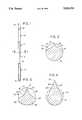
- FIG. 1is a side view of a bolt according to the invention
- FIG. 2is a sectional view taken along the line 2--2 of FIG. 1 of a first embodiment of the invention
- FIG. 3is a sectional view, similar to that of FIG. 2, of a second embodiment of the invention.
- FIG. 4is a sectional view, similar to that of FIG. 2, of a third embodiment of the invention.
- a boltof a substantially cylindrical shape, is constructed having an initial portion 10, a central portion 11 and a terminal portion 12.
- Initial portion 10which is perfectly cylindrical and of a length equal to about one third of the entire length of the bolt, has a short portion at upper end 14 in which the lateral surface is flattened in order to allow a suitable instrument to tighten up or slacken off the said bolt.
- Terminal portion 12is cylindrical, having an external diameter equal to the diameter of portion 10, is threaded externally and ends at its lower end in a tapering point 13.
- Central portion 11constitutes the fundamental characteristic of the invention.
- the lateral surface of said central portion 11has a cutting member 16 which extends parallel to the longitudinal axis of the bolt along the entire length of portion 11.
- the ends of the lateral surface of said portion 11merge into the lateral surfaces of preceding portion 10 and following portion 12 so as to avoid forming sharp edges which could harm anyone handling the bolt too casually, in addition to causing problems when the bolt is positioned in the patient's bone.
- said central portion 11has a substantially drop-shaped transverse cross-section and has a lateral surface consisting of a semicylindrical portion 18 which is a continuation of the corresponding part of portion 10, while the remainder, having the same plane of symmetry as said portion 18, has two portions 20, which are externally convex, connecting said portion 18 with the lateral surfaces 21 of cutting member 16.
- Said cylindrical surfaces 21, having an externally directed concavity, by means of their line of intersectiongive rise to edge 15 of said member 16, lying along the axis of symmetry of the said section, at a distance from the longitudinal axis of the bolt equal to the radius of said portion 18. In this way said edge 15 forms a prolongation of a generatrix of upper portion 10 and in turn extends into a generatrix of portion 12.
- a second embodiment of the inventionprovides a central portion 11' having a transverse cross-section which is again substantially in the form of a drop as illustrated in FIG. 3.
- Said portion 11'has a symmetrical lateral surface with respect to a plane passing through the longitudinal axis of the bolt consisting of a cylindrical portion 18' with a radius of curvature slightly greater than the radius of cylindrical portion 10, having its generatrix lying in the same plane of symmetry, as an extension to the generatrix of said portion 10, while the remaining portion has two portions 20' of variable curvature, which are externally convex, followed by two other portions 22, which are internally convex, joining said portion 18' with the lateral surfaces 21' of cutting member 16'.
- said flat surfaces 21'determine the edge 15' of said member 16' lying along the axis of symmetry of the said portion, at a distance from the longitudinal axis of the bolt equal to the radius of said portion 10.
- FIG. 4illustrates the transverse cross-section of central portion 11" of a third embodiment of the invention.
- Central portion 11"has a transverse cross-section which is still substantially in the shape of a drop and has a lateral surface which is symmetrical with respect to a plane passing through the longitudinal axis of the bolt.
- the said lateral surfaceconsists of a cylindrical portion 18" having a radius of curvature slightly less than the radius of cylindrical portion 10, the generatrix of which lies in the same plane of symmetry and is the extension of a generatrix of said portion 10, while the remaining portion consists of the two lateral surfaces 21" of cutting member 16". Through the line of their intersection said surfaces 21" give rise to the edge 15" of said member 16".
- Said edge 15" which lies in the plane of symmetry of the cross-sectionruns parallel to the longitudinal axis of the bolt at a distance from it of slightly more than the radius of cylindrical portion 10.
- edge 15"is merged into the surfaces of portions 10 and 12 at the two ends of portion 11" so as not to leave sharp edges.
- portion 12may be tapering or cylindrical, and may be provided with any known thread, either tapering or cylindrical. It is also clear that end 14 of the bolt according to the invention may also be shaped in a different manner from that illustrated provided that the said bolt can be engaged by a suitable instrument for tightening or slackening it.
- point 13 of the boltmay also not be pointed as illustrated in FIG. 1, but taper in a different way.
Landscapes
- Health & Medical Sciences (AREA)
- Orthopedic Medicine & Surgery (AREA)
- Surgery (AREA)
- Life Sciences & Earth Sciences (AREA)
- Heart & Thoracic Surgery (AREA)
- Nuclear Medicine, Radiotherapy & Molecular Imaging (AREA)
- Engineering & Computer Science (AREA)
- Biomedical Technology (AREA)
- Neurology (AREA)
- Medical Informatics (AREA)
- Molecular Biology (AREA)
- Animal Behavior & Ethology (AREA)
- General Health & Medical Sciences (AREA)
- Public Health (AREA)
- Veterinary Medicine (AREA)
- Surgical Instruments (AREA)
Abstract
Description
Claims (11)
Applications Claiming Priority (2)
| Application Number | Priority Date | Filing Date | Title |
|---|---|---|---|
| IT8984929AIT1234761B (en) | 1989-05-12 | 1989-05-12 | SCREW FOR ORTHOPEDIC SURGICAL USES, COMBINABLE WITH AN EXTERNAL FIXING DEVICE. |
| IT84929A/89 | 1989-05-12 |
Publications (1)
| Publication Number | Publication Date |
|---|---|
| US5026374Atrue US5026374A (en) | 1991-06-25 |
Family
ID=11325942
Family Applications (1)
| Application Number | Title | Priority Date | Filing Date |
|---|---|---|---|
| US07/415,991Expired - LifetimeUS5026374A (en) | 1989-05-12 | 1989-10-02 | Bolt for orthopaedic surgical use |
Country Status (5)
| Country | Link |
|---|---|
| US (1) | US5026374A (en) |
| DE (1) | DE3923099C1 (en) |
| FR (1) | FR2646769B1 (en) |
| GB (1) | GB2232085B (en) |
| IT (1) | IT1234761B (en) |
Cited By (29)
| Publication number | Priority date | Publication date | Assignee | Title |
|---|---|---|---|---|
| US5292326A (en)* | 1990-09-13 | 1994-03-08 | United States Surgical Corporation | Apparatus and method for subcuticular stapling of body tissue |
| US5389102A (en)* | 1990-09-13 | 1995-02-14 | United States Surgical Corporation | Apparatus and method for subcuticular stapling of body tissue |
| US5423856A (en)* | 1990-09-13 | 1995-06-13 | United States Surgical Corporation | Apparatus and method for subcuticular stapling of body tissue |
| US5643268A (en)* | 1994-09-27 | 1997-07-01 | Brainlab Med. Computersysteme Gmbh | Fixation pin for fixing a reference system to bony structures |
| US5662650A (en)* | 1995-05-12 | 1997-09-02 | Electro-Biology, Inc. | Method and apparatus for external fixation of large bones |
| US5743898A (en)* | 1995-05-12 | 1998-04-28 | Electro-Biology, Inc. | Method and apparatus for external fixation of small bones |
| US5976125A (en)* | 1995-08-29 | 1999-11-02 | The Cleveland Clinic Foundation | External distractor/fixator for the management of fractures and dislocations of interphalangeal joints |
| WO2000003648A1 (en)* | 1998-07-13 | 2000-01-27 | Sepitec Foundation | Osteosynthesis screw |
| US20020087160A1 (en)* | 2000-08-28 | 2002-07-04 | Ron Clark | Method and implant for securing ligament replacement into the knee |
| US6423061B1 (en) | 2000-03-14 | 2002-07-23 | Amei Technologies Inc. | High tibial osteotomy method and apparatus |
| US6678562B1 (en) | 2000-01-12 | 2004-01-13 | Amei Technologies Inc. | Combined tissue/bone growth stimulator and external fixation device |
| US20050197662A1 (en)* | 2000-08-28 | 2005-09-08 | Ron Clark | Method and implant for securing ligament replacement into the knee |
| US20060229604A1 (en)* | 2005-03-18 | 2006-10-12 | Olsen Ron A | Adjustable splint for osteosynthesis with modular components |
| US20060229605A1 (en)* | 2005-03-18 | 2006-10-12 | Olsen Ron A | Adjustable splint for osteosynthesis with incrementing assembly for adjustment in predetermined increments |
| US20070162028A1 (en)* | 2005-12-09 | 2007-07-12 | Jesse Jackson | Cannulated screw |
| US20080228271A1 (en)* | 2007-03-13 | 2008-09-18 | Biomet Sports Medicine, Inc. | Method and apparatus for graft fixation |
| US7645279B1 (en) | 2003-07-25 | 2010-01-12 | Haupt Bruce F | Bone fixation method |
| US7846162B2 (en) | 2005-05-18 | 2010-12-07 | Sonoma Orthopedic Products, Inc. | Minimally invasive actuable bone fixation devices |
| US7896917B2 (en) | 2003-10-15 | 2011-03-01 | Biomet Sports Medicine, Llc | Method and apparatus for graft fixation |
| US7909825B2 (en) | 2006-11-22 | 2011-03-22 | Sonoma Orthepedic Products, Inc. | Fracture fixation device, tools and methods |
| US8002778B1 (en) | 2004-06-28 | 2011-08-23 | Biomet Sports Medicine, Llc | Crosspin and method for inserting the same during soft ligament repair |
| US8287539B2 (en) | 2005-05-18 | 2012-10-16 | Sonoma Orthopedic Products, Inc. | Fracture fixation device, tools and methods |
| CN104352269A (en)* | 2014-12-02 | 2015-02-18 | 超微(上海)医院投资管理有限公司 | Orthopedic external fixation frame half needle with cutting edge |
| US8961516B2 (en) | 2005-05-18 | 2015-02-24 | Sonoma Orthopedic Products, Inc. | Straight intramedullary fracture fixation devices and methods |
| US9060820B2 (en) | 2005-05-18 | 2015-06-23 | Sonoma Orthopedic Products, Inc. | Segmented intramedullary fracture fixation devices and methods |
| US9155574B2 (en) | 2006-05-17 | 2015-10-13 | Sonoma Orthopedic Products, Inc. | Bone fixation device, tools and methods |
| US9770278B2 (en) | 2014-01-17 | 2017-09-26 | Arthrex, Inc. | Dual tip guide wire |
| US9814499B2 (en) | 2014-09-30 | 2017-11-14 | Arthrex, Inc. | Intramedullary fracture fixation devices and methods |
| US10874433B2 (en) | 2017-01-30 | 2020-12-29 | Stryker European Holdings I, Llc | Strut attachments for external fixation frame |
Families Citing this family (3)
| Publication number | Priority date | Publication date | Assignee | Title |
|---|---|---|---|---|
| DE19611881C1 (en)* | 1996-03-26 | 1997-06-26 | Ewald Rueter | External fixture system for bone fracture, with screws and cross pieces |
| RU2134081C1 (en)* | 1997-10-07 | 1999-08-10 | Бейдик Олег Викторович | Rod for external perosseous osteosynthesis |
| DE19831336C2 (en)* | 1998-07-13 | 2003-06-18 | Sepitec Foundation Vaduz | Bone screw, especially for use with translaminar vertebrae |
Citations (11)
| Publication number | Priority date | Publication date | Assignee | Title |
|---|---|---|---|---|
| US31749A (en)* | 1861-03-19 | Improvement in plows | ||
| US411152A (en)* | 1889-09-17 | Pin for hinges of stove-doors | ||
| US440331A (en)* | 1890-11-11 | Island | ||
| US461621A (en)* | 1891-10-20 | Island | ||
| US470804A (en)* | 1892-03-15 | Wood-screw | ||
| US1969796A (en)* | 1932-04-08 | 1934-08-14 | Dardelet Threadlock Corp | Separable fastener and installation thereof |
| US1988925A (en)* | 1932-09-10 | 1935-01-22 | Dardelet Threadlock Corp | Separable fastener and installation thereof |
| US3051169A (en)* | 1957-12-07 | 1962-08-28 | Stille Werner Ab | Surgical screw connector |
| US3118444A (en)* | 1961-11-20 | 1964-01-21 | Jr Jose C Serrato | Forearm rod for fractures |
| US4338054A (en)* | 1979-11-19 | 1982-07-06 | Dahl Norman C | Solid externally threaded fasteners having greatly increased ductility |
| US4653244A (en)* | 1986-01-16 | 1987-03-31 | Farrell Mark A | Fastener element |
Family Cites Families (5)
| Publication number | Priority date | Publication date | Assignee | Title |
|---|---|---|---|---|
| GB817525A (en)* | 1956-10-05 | 1959-07-29 | Maison Drapier Van Steenbruggh | Improvements relating to pegs for pinning long bones through the medullary canal |
| DE1805210A1 (en)* | 1967-12-29 | 1969-10-16 | Augsburg Nuernberg Ag Zweignie | Nose screw |
| US3915162A (en)* | 1974-02-13 | 1975-10-28 | Peter S Miller | Orthopedic pin identification means |
| DE3701533A1 (en)* | 1987-01-21 | 1988-08-04 | Medi System Gmbh | OSTEOSYNTHESIS TOOLS |
| DE8815977U1 (en)* | 1988-02-05 | 1989-02-16 | Orthoplant Endoprothetik GmbH i.L., 28259 Bremen | Rod-shaped fastening element |
- 1989
- 1989-05-12ITIT8984929Apatent/IT1234761B/enactive
- 1989-06-30FRFR898908791Apatent/FR2646769B1/ennot_activeExpired - Lifetime
- 1989-07-05GBGB8915433Apatent/GB2232085B/ennot_activeExpired - Lifetime
- 1989-07-13DEDE3923099Apatent/DE3923099C1/denot_activeExpired - Lifetime
- 1989-10-02USUS07/415,991patent/US5026374A/ennot_activeExpired - Lifetime
Patent Citations (11)
| Publication number | Priority date | Publication date | Assignee | Title |
|---|---|---|---|---|
| US31749A (en)* | 1861-03-19 | Improvement in plows | ||
| US411152A (en)* | 1889-09-17 | Pin for hinges of stove-doors | ||
| US440331A (en)* | 1890-11-11 | Island | ||
| US461621A (en)* | 1891-10-20 | Island | ||
| US470804A (en)* | 1892-03-15 | Wood-screw | ||
| US1969796A (en)* | 1932-04-08 | 1934-08-14 | Dardelet Threadlock Corp | Separable fastener and installation thereof |
| US1988925A (en)* | 1932-09-10 | 1935-01-22 | Dardelet Threadlock Corp | Separable fastener and installation thereof |
| US3051169A (en)* | 1957-12-07 | 1962-08-28 | Stille Werner Ab | Surgical screw connector |
| US3118444A (en)* | 1961-11-20 | 1964-01-21 | Jr Jose C Serrato | Forearm rod for fractures |
| US4338054A (en)* | 1979-11-19 | 1982-07-06 | Dahl Norman C | Solid externally threaded fasteners having greatly increased ductility |
| US4653244A (en)* | 1986-01-16 | 1987-03-31 | Farrell Mark A | Fastener element |
Cited By (55)
| Publication number | Priority date | Publication date | Assignee | Title |
|---|---|---|---|---|
| US5292326A (en)* | 1990-09-13 | 1994-03-08 | United States Surgical Corporation | Apparatus and method for subcuticular stapling of body tissue |
| US5389102A (en)* | 1990-09-13 | 1995-02-14 | United States Surgical Corporation | Apparatus and method for subcuticular stapling of body tissue |
| US5423856A (en)* | 1990-09-13 | 1995-06-13 | United States Surgical Corporation | Apparatus and method for subcuticular stapling of body tissue |
| US5489287A (en)* | 1990-09-13 | 1996-02-06 | United States Surgical Corporation | Apparatus and method for subcuticular stapling of body tissue |
| US5573541A (en)* | 1990-09-13 | 1996-11-12 | United States Surgical Corporation | Apparatus and method for subcuticular stapling of body tissue |
| US5643268A (en)* | 1994-09-27 | 1997-07-01 | Brainlab Med. Computersysteme Gmbh | Fixation pin for fixing a reference system to bony structures |
| US5662650A (en)* | 1995-05-12 | 1997-09-02 | Electro-Biology, Inc. | Method and apparatus for external fixation of large bones |
| US5743898A (en)* | 1995-05-12 | 1998-04-28 | Electro-Biology, Inc. | Method and apparatus for external fixation of small bones |
| US6171308B1 (en) | 1995-05-12 | 2001-01-09 | Kirk Jay Bailey | Method and apparatus for external fixation of large bones |
| US5976125A (en)* | 1995-08-29 | 1999-11-02 | The Cleveland Clinic Foundation | External distractor/fixator for the management of fractures and dislocations of interphalangeal joints |
| WO2000003648A1 (en)* | 1998-07-13 | 2000-01-27 | Sepitec Foundation | Osteosynthesis screw |
| US6699250B1 (en)* | 1998-07-13 | 2004-03-02 | Sepitec Foundation | Osteosynthesis screw |
| US6678562B1 (en) | 2000-01-12 | 2004-01-13 | Amei Technologies Inc. | Combined tissue/bone growth stimulator and external fixation device |
| US6423061B1 (en) | 2000-03-14 | 2002-07-23 | Amei Technologies Inc. | High tibial osteotomy method and apparatus |
| US20020164905A1 (en)* | 2000-03-14 | 2002-11-07 | Amei Technologies Inc., A Delaware Corporation | Osteotomy guide and method |
| US7530999B2 (en) | 2000-08-28 | 2009-05-12 | Biomet Sports Medicine, Llc | Method and implant for securing ligament replacement into the knee |
| US6878166B2 (en)* | 2000-08-28 | 2005-04-12 | Ron Clark | Method and implant for securing ligament replacement into the knee |
| US20050197662A1 (en)* | 2000-08-28 | 2005-09-08 | Ron Clark | Method and implant for securing ligament replacement into the knee |
| US7837718B2 (en) | 2000-08-28 | 2010-11-23 | Biomet Sports Medicine, Llc | Method and implant for securing ligament replacement into the knee |
| US20020087160A1 (en)* | 2000-08-28 | 2002-07-04 | Ron Clark | Method and implant for securing ligament replacement into the knee |
| US7645279B1 (en) | 2003-07-25 | 2010-01-12 | Haupt Bruce F | Bone fixation method |
| US8784489B2 (en) | 2003-10-15 | 2014-07-22 | Biomet Sports Medicine, Llc | Method and apparatus for graft fixation |
| US20110153018A1 (en)* | 2003-10-15 | 2011-06-23 | Biomet Sports Medicine, Llc | Method and Apparatus for Graft Fixation |
| US7896917B2 (en) | 2003-10-15 | 2011-03-01 | Biomet Sports Medicine, Llc | Method and apparatus for graft fixation |
| US8002778B1 (en) | 2004-06-28 | 2011-08-23 | Biomet Sports Medicine, Llc | Crosspin and method for inserting the same during soft ligament repair |
| US7575575B2 (en) | 2005-03-18 | 2009-08-18 | Ron Anthon Olsen | Adjustable splint for osteosynthesis with modular components |
| US20060229603A1 (en)* | 2005-03-18 | 2006-10-12 | Olsen Ron A | Adjustable splint for osteosynthesis with modular joint |
| US7588571B2 (en) | 2005-03-18 | 2009-09-15 | Ron Anthon Olsen | Adjustable splint for osteosynthesis with modular joint |
| US7507240B2 (en) | 2005-03-18 | 2009-03-24 | Ron Anthon Olsen | Adjustable splint for osteosynthesis |
| US20060229605A1 (en)* | 2005-03-18 | 2006-10-12 | Olsen Ron A | Adjustable splint for osteosynthesis with incrementing assembly for adjustment in predetermined increments |
| US20060229602A1 (en)* | 2005-03-18 | 2006-10-12 | Olsen Ron A | Adjustable splint for osteosynthesis |
| US20060229604A1 (en)* | 2005-03-18 | 2006-10-12 | Olsen Ron A | Adjustable splint for osteosynthesis with modular components |
| US7942875B2 (en) | 2005-05-18 | 2011-05-17 | Sonoma Orthopedic Products, Inc. | Methods of using minimally invasive actuable bone fixation devices |
| US9060820B2 (en) | 2005-05-18 | 2015-06-23 | Sonoma Orthopedic Products, Inc. | Segmented intramedullary fracture fixation devices and methods |
| US7914533B2 (en) | 2005-05-18 | 2011-03-29 | Sonoma Orthopedic Products, Inc. | Minimally invasive actuable bone fixation devices |
| US7846162B2 (en) | 2005-05-18 | 2010-12-07 | Sonoma Orthopedic Products, Inc. | Minimally invasive actuable bone fixation devices |
| US8961516B2 (en) | 2005-05-18 | 2015-02-24 | Sonoma Orthopedic Products, Inc. | Straight intramedullary fracture fixation devices and methods |
| US8287539B2 (en) | 2005-05-18 | 2012-10-16 | Sonoma Orthopedic Products, Inc. | Fracture fixation device, tools and methods |
| US8287541B2 (en) | 2005-05-18 | 2012-10-16 | Sonoma Orthopedic Products, Inc. | Fracture fixation device, tools and methods |
| US20070162028A1 (en)* | 2005-12-09 | 2007-07-12 | Jesse Jackson | Cannulated screw |
| US7731738B2 (en) | 2005-12-09 | 2010-06-08 | Orthopro, Llc | Cannulated screw |
| US9155574B2 (en) | 2006-05-17 | 2015-10-13 | Sonoma Orthopedic Products, Inc. | Bone fixation device, tools and methods |
| US8439917B2 (en) | 2006-11-22 | 2013-05-14 | Sonoma Orthopedic Products, Inc. | Fracture fixation device, tools and methods |
| US9259250B2 (en) | 2006-11-22 | 2016-02-16 | Sonoma Orthopedic Products, Inc. | Fracture fixation device, tools and methods |
| US7909825B2 (en) | 2006-11-22 | 2011-03-22 | Sonoma Orthepedic Products, Inc. | Fracture fixation device, tools and methods |
| US8147546B2 (en) | 2007-03-13 | 2012-04-03 | Biomet Sports Medicine, Llc | Method and apparatus for graft fixation |
| US20080228271A1 (en)* | 2007-03-13 | 2008-09-18 | Biomet Sports Medicine, Inc. | Method and apparatus for graft fixation |
| US8900301B2 (en) | 2007-03-13 | 2014-12-02 | Biomet Sports Medicine, Llc | Method and apparatus for graft fixation |
| US9770278B2 (en) | 2014-01-17 | 2017-09-26 | Arthrex, Inc. | Dual tip guide wire |
| US9814499B2 (en) | 2014-09-30 | 2017-11-14 | Arthrex, Inc. | Intramedullary fracture fixation devices and methods |
| US10548648B2 (en) | 2014-09-30 | 2020-02-04 | Arthrex, Inc. | Intramedullary fracture fixation devices and methods |
| CN104352269A (en)* | 2014-12-02 | 2015-02-18 | 超微(上海)医院投资管理有限公司 | Orthopedic external fixation frame half needle with cutting edge |
| US10874433B2 (en) | 2017-01-30 | 2020-12-29 | Stryker European Holdings I, Llc | Strut attachments for external fixation frame |
| US11723690B2 (en) | 2017-01-30 | 2023-08-15 | Stryker European Operations Holdings Llc | Strut attachments for external fixation frame |
| US12369948B2 (en) | 2017-01-30 | 2025-07-29 | Stryker European Operations Holdings Llc | Strut attachments for external fixation frame |
Also Published As
| Publication number | Publication date |
|---|---|
| IT1234761B (en) | 1992-05-26 |
| FR2646769A1 (en) | 1990-11-16 |
| FR2646769B1 (en) | 1992-04-03 |
| GB2232085B (en) | 1992-11-11 |
| GB8915433D0 (en) | 1989-08-23 |
| GB2232085A (en) | 1990-12-05 |
| IT8984929A0 (en) | 1989-05-12 |
| DE3923099C1 (en) | 1990-10-04 |
Similar Documents
| Publication | Publication Date | Title |
|---|---|---|
| US5026374A (en) | Bolt for orthopaedic surgical use | |
| US5147381A (en) | Surgical clip | |
| US5575791A (en) | Universal eccentric fixation mechanism for orthopedic surgery | |
| EP0934027B1 (en) | Multi-axial bone screw assembly | |
| US5242446A (en) | Connector for a spinal column corrective device | |
| US5468241A (en) | Support device for the human vertebral column | |
| CA2413501C (en) | Spinal implant for an osteosynthesis device | |
| EP0086552B1 (en) | Bone fracture fixation nail | |
| US6053917A (en) | Multi-axial bone screw assembly | |
| US4950269A (en) | Spinal column fixation device | |
| US4901721A (en) | Suturing device | |
| US7338490B2 (en) | Reduction cable and bone anchor | |
| US8298274B2 (en) | Multi-axial bone screw assembly | |
| US4414721A (en) | Occlusive clip and applicator for constricting flexible tubular members | |
| US5509920A (en) | Surgical hemostatic clip | |
| KR20030038556A (en) | Tension band clip | |
| CA2371394C (en) | Shape-memory coupling especially for spinal fixator | |
| EP1545326B1 (en) | Union stress needle | |
| JP4130411B2 (en) | Device for joining the vertical support and bone | |
| US5304178A (en) | Sublaminar wire | |
| JPH08505785A (en) | Lumbar-sacral joint and instrument screws to correct spondylolisthesis by posterior approach | |
| AU2001266265A1 (en) | Spinal implant for an osteosynthesis device | |
| EP0683653A1 (en) | Spinal fixation system | |
| DE69918068T2 (en) | CABLE SHEAR ARRANGEMENT FOR BONE FIXATION | |
| JPH0586221B2 (en) |
Legal Events
| Date | Code | Title | Description |
|---|---|---|---|
| AS | Assignment | Owner name:ORTHOFIX S.R.L., 9, VIA DELLE NAZIONI, Z.I. BUSSOL Free format text:ASSIGNMENT OF ASSIGNORS INTEREST.;ASSIGNORS:DEZZA, OTTAVIO;FACCIOLI, GIOVANNI;REEL/FRAME:005147/0835 Effective date:19890918 | |
| STCF | Information on status: patent grant | Free format text:PATENTED CASE | |
| FEPP | Fee payment procedure | Free format text:PAYOR NUMBER ASSIGNED (ORIGINAL EVENT CODE: ASPN); ENTITY STATUS OF PATENT OWNER: SMALL ENTITY | |
| FPAY | Fee payment | Year of fee payment:4 | |
| FPAY | Fee payment | Year of fee payment:8 | |
| FEPP | Fee payment procedure | Free format text:PAYER NUMBER DE-ASSIGNED (ORIGINAL EVENT CODE: RMPN); ENTITY STATUS OF PATENT OWNER: SMALL ENTITY Free format text:PAYOR NUMBER ASSIGNED (ORIGINAL EVENT CODE: ASPN); ENTITY STATUS OF PATENT OWNER: SMALL ENTITY | |
| FPAY | Fee payment | Year of fee payment:12 | |
| AS | Assignment | Owner name:ORTHOFIX INTERNATIONAL B.V., NETHERLANDS Free format text:ASSIGNMENT OF ASSIGNORS INTEREST;ASSIGNOR:ORTHOFIX S.R.L.;REEL/FRAME:014446/0135 Effective date:20030101 |