US5026367A - Laser angioplasty catheter and a method for use thereof - Google Patents
Laser angioplasty catheter and a method for use thereofDownload PDFInfo
- Publication number
- US5026367A US5026367AUS07/169,937US16993788AUS5026367AUS 5026367 AUS5026367 AUS 5026367AUS 16993788 AUS16993788 AUS 16993788AUS 5026367 AUS5026367 AUS 5026367A
- Authority
- US
- United States
- Prior art keywords
- catheter
- distal end
- end portion
- lumen
- extending
- Prior art date
- Legal status (The legal status is an assumption and is not a legal conclusion. Google has not performed a legal analysis and makes no representation as to the accuracy of the status listed.)
- Expired - Fee Related
Links
Images


Classifications
- A—HUMAN NECESSITIES
- A61—MEDICAL OR VETERINARY SCIENCE; HYGIENE
- A61B—DIAGNOSIS; SURGERY; IDENTIFICATION
- A61B18/00—Surgical instruments, devices or methods for transferring non-mechanical forms of energy to or from the body
- A61B18/18—Surgical instruments, devices or methods for transferring non-mechanical forms of energy to or from the body by applying electromagnetic radiation, e.g. microwaves
- A61B18/20—Surgical instruments, devices or methods for transferring non-mechanical forms of energy to or from the body by applying electromagnetic radiation, e.g. microwaves using laser
- A61B18/22—Surgical instruments, devices or methods for transferring non-mechanical forms of energy to or from the body by applying electromagnetic radiation, e.g. microwaves using laser the beam being directed along or through a flexible conduit, e.g. an optical fibre; Couplings or hand-pieces therefor
- A61B18/24—Surgical instruments, devices or methods for transferring non-mechanical forms of energy to or from the body by applying electromagnetic radiation, e.g. microwaves using laser the beam being directed along or through a flexible conduit, e.g. an optical fibre; Couplings or hand-pieces therefor with a catheter
- A61B18/245—Surgical instruments, devices or methods for transferring non-mechanical forms of energy to or from the body by applying electromagnetic radiation, e.g. microwaves using laser the beam being directed along or through a flexible conduit, e.g. an optical fibre; Couplings or hand-pieces therefor with a catheter for removing obstructions in blood vessels or calculi
- A—HUMAN NECESSITIES
- A61—MEDICAL OR VETERINARY SCIENCE; HYGIENE
- A61B—DIAGNOSIS; SURGERY; IDENTIFICATION
- A61B17/00—Surgical instruments, devices or methods
- A61B2017/00017—Electrical control of surgical instruments
- A61B2017/00137—Details of operation mode
- A61B2017/00154—Details of operation mode pulsed
- A—HUMAN NECESSITIES
- A61—MEDICAL OR VETERINARY SCIENCE; HYGIENE
- A61B—DIAGNOSIS; SURGERY; IDENTIFICATION
- A61B17/00—Surgical instruments, devices or methods
- A61B2017/00831—Material properties
- A61B2017/0084—Material properties low friction
- A—HUMAN NECESSITIES
- A61—MEDICAL OR VETERINARY SCIENCE; HYGIENE
- A61B—DIAGNOSIS; SURGERY; IDENTIFICATION
- A61B17/00—Surgical instruments, devices or methods
- A61B17/22—Implements for squeezing-off ulcers or the like on inner organs of the body; Implements for scraping-out cavities of body organs, e.g. bones; for invasive removal or destruction of calculus using mechanical vibrations; for removing obstructions in blood vessels, not otherwise provided for
- A61B2017/22051—Implements for squeezing-off ulcers or the like on inner organs of the body; Implements for scraping-out cavities of body organs, e.g. bones; for invasive removal or destruction of calculus using mechanical vibrations; for removing obstructions in blood vessels, not otherwise provided for with an inflatable part, e.g. balloon, for positioning, blocking, or immobilisation
- A61B2017/22054—Implements for squeezing-off ulcers or the like on inner organs of the body; Implements for scraping-out cavities of body organs, e.g. bones; for invasive removal or destruction of calculus using mechanical vibrations; for removing obstructions in blood vessels, not otherwise provided for with an inflatable part, e.g. balloon, for positioning, blocking, or immobilisation with two balloons
- A—HUMAN NECESSITIES
- A61—MEDICAL OR VETERINARY SCIENCE; HYGIENE
- A61B—DIAGNOSIS; SURGERY; IDENTIFICATION
- A61B17/00—Surgical instruments, devices or methods
- A61B17/22—Implements for squeezing-off ulcers or the like on inner organs of the body; Implements for scraping-out cavities of body organs, e.g. bones; for invasive removal or destruction of calculus using mechanical vibrations; for removing obstructions in blood vessels, not otherwise provided for
- A61B2017/22051—Implements for squeezing-off ulcers or the like on inner organs of the body; Implements for scraping-out cavities of body organs, e.g. bones; for invasive removal or destruction of calculus using mechanical vibrations; for removing obstructions in blood vessels, not otherwise provided for with an inflatable part, e.g. balloon, for positioning, blocking, or immobilisation
- A61B2017/22065—Functions of balloons
- A61B2017/22067—Blocking; Occlusion
- A—HUMAN NECESSITIES
- A61—MEDICAL OR VETERINARY SCIENCE; HYGIENE
- A61B—DIAGNOSIS; SURGERY; IDENTIFICATION
- A61B17/00—Surgical instruments, devices or methods
- A61B17/22—Implements for squeezing-off ulcers or the like on inner organs of the body; Implements for scraping-out cavities of body organs, e.g. bones; for invasive removal or destruction of calculus using mechanical vibrations; for removing obstructions in blood vessels, not otherwise provided for
- A61B2017/22051—Implements for squeezing-off ulcers or the like on inner organs of the body; Implements for scraping-out cavities of body organs, e.g. bones; for invasive removal or destruction of calculus using mechanical vibrations; for removing obstructions in blood vessels, not otherwise provided for with an inflatable part, e.g. balloon, for positioning, blocking, or immobilisation
- A61B2017/22065—Functions of balloons
- A61B2017/22069—Immobilising; Stabilising
- A—HUMAN NECESSITIES
- A61—MEDICAL OR VETERINARY SCIENCE; HYGIENE
- A61B—DIAGNOSIS; SURGERY; IDENTIFICATION
- A61B18/00—Surgical instruments, devices or methods for transferring non-mechanical forms of energy to or from the body
- A61B18/18—Surgical instruments, devices or methods for transferring non-mechanical forms of energy to or from the body by applying electromagnetic radiation, e.g. microwaves
- A61B18/1815—Surgical instruments, devices or methods for transferring non-mechanical forms of energy to or from the body by applying electromagnetic radiation, e.g. microwaves using microwaves
- A61B2018/1861—Surgical instruments, devices or methods for transferring non-mechanical forms of energy to or from the body by applying electromagnetic radiation, e.g. microwaves using microwaves with an instrument inserted into a body lumen or cavity, e.g. a catheter
Definitions
- the inventionrelates to laser angioplasty catheters which are adapted to be inserted into ducts within the body of a patient such as blood vessels including arteries and veins.
- the catheters of t he inventionare adapted to penetrate and disintegrate blockages, obstructions, occlusions, etc., or the like within the ducts in which the catheters are inserted.
- the catheters of the inventionenable laser energy transmitted by an optical fiber or a bundle of optical fibers to be released from the distal end of the catheter to disintegrate or vaporize obstructions within blood vessels such as plaque in coronary, femoral, and other arteries.
- the distal end of the catheteris positioned adjacent to the obstruction such as an occlusion or arteriosclerotic plaque which is to be removed from the duct.
- the laser angioplasty catheter of the inventionmust be adapted to prevent the laser energy from intersecting the internal wall of the duct at an angle or to a degree which could result in the possibility of damaging the duct.
- fluids within the ductsuch as blood within a blood vessel must be prevented from interfering with the transmission and release of the laser energy at the distal end of the catheter. It is also necessary to have control of the rotational position of the distal end of the catheter with respect to the duct in order that the catheter may operate upon an obstruction within a duct regardless of its circumferential position of the obstruction within the duct.
- a laser angioplasty catheterhaving a flexible shaft adapted to be inserted into a duct such as a blood vessel with a single or solid optical fiber or a bundle of optical fibers extending through the shaft to adjacent the distal end thereof.
- Laser energysuch as pulsed laser energy is delivered to the proximal end of the optical fiber bundle and is emitted from the distal end thereof.
- the laser energyintersects a blockage within the blood vessel, the laser energy disintegrates or vaporizes the blockage.
- suctionto a lumen extending through the shaft, debris resulting from the disintegration or vaporization of the blockage can be withdrawn from the blood vessel
- An inflatable balloon disposed opposite the abutmentscan be controllably inflated to urge the abutments toward the inner surface of the duct and thereby receive the blockage with the jaw between the abutments.
- Laser energyis emitted by the distal end portion of an optical fiber or fibers into the jaw in order to vaporize the blockage.
- the abutments adjacent to the distal end of the catheterprevent the laser energy from being propagated downstream of the distal end of the catheter and thereby prevent the laser energy from contacting the inner surface of the duct.
- a passage extending through the length of the catheteris adapted to apply suction to the jaw disposed between the abutments in order to remove debris therefrom.
- U.S. Pat. No. 4,685,458, issued Aug. 11, 1987, which is a division of U.S. Pat. No. 4,627,436,discloses a catheter similar to that of the 4,627,436 patent, but with an elongated element such as a cutting blade or a hot-wire extending between the abutments and adjacent to the jaw therebetween.
- the blade or hot-wireis adapted to cut or sever a blockage from the inner surface of the duct rather than to vaporize the obstruction by the application of laser energy.
- U.S. Pat. No. 4,207,874, issued June 17, 1980,is another example of a laser angioplasty catheter.
- laser energydisintegrates or vaporizes an obstruction and suction is applied to a passage extending through the length of the catheter to withdraw debris produced by the application of the laser energy.
- the invention of a laser angioplasty catheter device for disintegrating or vaporizing undesired material from a duct within the body of a patientcomprises a catheter adapted to be disposed within the duct and having a snout-shaped distal end portion with a tip at one side thereof and a tapered surface extending from the tip toward the opposite side thereof. Means are provided adjacent to the distal end of the catheter for emitting laser energy from an opening in the tapered surface obstruction in the duct.
- meansare provided for irrigating the distal end portion of the catheter adjacent to the obstruction being vaporized.
- meansare provided for removing debris of the obstruction being vaporized from adjacent the distal end portion of the catheter.
- the catheteris provided with a core wire extending through an internal passage within the catheter to adjacent the distal end portion thereof.
- the core wireis secured to the catheter.
- the optical fiber or fibers of the catheter deviceare extended through a lumen within the catheter adjacent the distal end portion of the catheter.
- the distal end of the lumenis provided with an orifice or nozzle which enables the velocity of a flow of an irrigating fluid delivered by the lumen to be controlled as it passes out of the orifice.
- a laser angioplasty catheterhaving a snout-shaped distal end portion with a tapered surface extending from the tip of the snout-shaped end portion for emitting pulsed laser energy from an opening in the tapered surface.
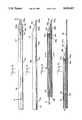
- FIG. 1is a perspective view of an embodiment of the laser angioplasty catheter of the invention showing the snout-shaped distal end portion thereof and connections to the proximal end portion thereof;
- FIG. 2is a fragmentary plan view of an embodiment of the catheter of the invention having a snout-shaped distal end portion;
- FIG. 3is a fragmentary elevation view of the catheter of FIG. 2;
- FIG. 4is a fragmentary vertical section taken along line 4--4 in FIG. 2 and showing the optical fibers for directing laser energy through an opening in the snout-shaped distal end portion of the catheter and the arch support for supporting the shaft of the catheter;
- FIG. 5is vertical section taken along line 5--5 in FIG. 4 and showing a passage therein for irrigating fluid and the optical fibers and a lumen therein for aspiration;
- FIG. 6is a vertical section view showing another embodiment of the catheter device with a guide wire mounted adjacent to the tip of the snout-shaped distal end portion;
- FIG. 7Ais a fragmentary plan view showing an arch support for the distal end of the catheter with the end tab thereof in an intermediate position;
- FIG. 7Bis a fragmentary plan view showing the arch support for the distal end of the catheter with the end tab thereof in its final position;
- FIG. 8is a fragmentary perspective view of the exterior of the orifice at the distal end of the arch support
- FIG. 9is a fragmentary perspective view of the orifice at the distal end of the arch support.
- FIG. 10is a fragmentary vertical section showing an orifice for directing irrigation liquid into the elongated opening at the distal end portion of the catheter;
- FIG. 11is a graphical representation of the flow velocity before, through and beyond the orifice of FIG. 10;
- FIG. 12is a graphical representation of the static pressure related to the velocities shown in FIG. 11;
- FIG. 13is a fragmentary vertical section showing a guidewire extending through the catheter
- FIG. 14is a fragmentary vertical section showing the aspiration lumen of the catheter
- FIG. 15is a fragmentary view of the catheter showing an occlusion balloon and a positioning balloon.
- FIG. 16is a fragmentary perspective view showing the snout-shaped distal end portion adjacent undesired material in a duct;
- FIG. 17is a fragmentary vertical section showing an embodiment of a rotatable connection of the optical fiber of the catheter device to a source of pulsed laser energy;
- FIG. 18is a fragmentary vertical section of another embodiment of a rotatable connection of the optical fiber to a source of pulsed laser energy.
- the laser angioplasty catheter 30 of the inventionis adapted to be disposed within a duct in the body of a patient such as a blood vessel or an artery.
- the catheter shaft 32has a snout-shaped end portion 33 which terminates in tip 33a.
- Snout-shaped end portion 33comprises cylindrical surface 33b at one side and tapered or sloping surface 33c at the opposite side.
- the snout-shaped end portionenables the end portion to contact the wall of the blood vessel and then to be deflected toward the center of the interior of the blood vessel.
- irrigation lumen 35which extends to elongated opening 34 in communication with elliptically-shaped window 33d in tapered surface 33c.
- irrigation liquidcan be delivered to connector 37 and then through line 37a to junction 38.
- the passage of line 39is connected to irrigation lumen 35 and in this way, a flow of irrigation liquid such as saline can be delivered by irrigation lumen 35 to opening 34 and thereby to window 33d.
- a fiber optic devicesuch as single or solid optical fiber or a bundle of optical fibers, hereinafter collectively referred to as "optical fiber”, e.g., optical fiber 41 extends from proximal end 32a (FIG. 1) of the catheter shaft 32 to the distal end 36a of arch support 36 (FIG. 6).
- Laser source 42(FIG. 1) by means of coupling 43 is connected to optical fiber 44 which leads to rotary connector 45 which enables the optical fiber 46 to rotate freely with respect to the laser source.
- Optical fiber 46extends from rotary connector 45 to junction 38. Beyond the junction 38, the optical fiber 46a extends through line 39 which is adapted to carry irrigation fluid from a supply (not shown) to which coupling 37 and line 37a are connected. Line 39 is connected to coupling 40. Within the coupling 40, optical fiber 41 enter passage 35 which extends to opening 34.
- Aspiration lumen 48which is shown by dash lines in FIGS. 2 and 3 and in FIG. 5 extends from proximal end portion 32a of the catheter shaft to adjacent elongated opening 34 where the aspiration passage is connected to aspiration notch 48b (FIGS. 2, 3 and 4) which is on the side of the catheter opposite elongated opening 34.
- the proximal end of aspiration lumen 48 within coupling 40is connected to line 49 which in turn is coupled to knob 50.
- Knob 50has a passage therethrough (not shown). Line 49 can be connected by the passage in knob 50 to a source 53 of negative pressure or suction (not shown).
- a core wire 54can be extended through the aspiration lumen 48 if aspiration is not to be used.
- Distal end portion 54a of the core wire 54(FIG. 14) is secured by bonding or like processes to snout-shaped end portion 33 of the catheter 30.
- core wire 54extends to the proximal end portion 32a (FIG. 1) of catheter shaft 32, extends through coupling 40, and then through the interior of line 49 which provides negative pressure to aspiration passage 48.
- core wire 54can be extended outwardly from coupling 40 and through line 49 to operating knob 50. Rotation of knob 50 enables core wire 54 to be rotated.
- the core wiremay be coated with materials such as fluorocarbon resin materials to reduce friction between the core wire and the aspiration passage when the core wire is rotated.
- Rotation of core wire 54 by knob 50 in either of the directions shown by the arrows in FIG. 1causes the core wire 54 to rotate freely within aspiration passage 48; however, since distal end portion 54a (FIG. 14) of the core wire is bonded or secured to snout-shaped end portion 33 of the catheter 32, the end portion 33 of the catheter is rotated in conjunction with rotation of the core wire 54. As a result, the snout-shaped end portion of catheter 33 can be rotated by the core wire 54 without rotating the remainder of shaft 32 of catheter device 30.
- the core wiremay have a varying thickness with the greater thickness at the proximal end thereof. This provision minimizes "wind-up" in the core wire when it is rotated, increases flexibility at the distal end of the core wire, and reduces friction and thereby resistance to rotation of the core wire in the catheter.
- optical fiber 41can be used by connecting the distal end 41a of the optical fiber to the distal end portion 33 of the catheter while the remainder of the optical fiber is free to rotate in its lumen.
- the distal end portion of the cathetercan be rotated.
- the distal end portion of catheter 30can, as an option, be provided with occlusion balloon 55 and positioning balloon 56.
- Lumen 57(FIGS. 3 and 5) which is in communication by port 57a (FIG. 3) with the occlusion balloon 55 as shown in FIGS. 1 and 15 extends through the catheter shaft 32, through coupling 40, to line 58, through valve 59 to a source of positive liquid (saline, for example) pressure such as syringe 59a.
- a source of positive liquid (saline, for example) pressuresuch as syringe 59a.
- the level of blood pressure adjacent the snout-shaped distal end portion 33 of the cathetercould cause a flow of blood along the catheter but for the blocking of the blood vessel by the occlusion balloon.
- the catheter of the inventionis applied to arterial blood vessels 65 where the heart and such vessels have been temporarily bypassed by a blood pumping apparatus, then the occlusion balloon is unnecessary (FIG. 16).
- Optional positioning balloon 56 as shown in FIGS. 1 and 15is connected by port 62a (FIG. 3) to passage 62 (FIG. 5) which extends through the catheter shaft 32 to its proximal end portion 32a.
- Passage 62is connected through coupling 40 to line 63 (FIG. 1) which is connected to valve 64 and in turn to a source of positive liquid pressure such as syringe 65.
- line 63FIG. 1
- a source of positive liquid pressuresuch as syringe 65.
- the positioning balloon 52is disposed at a side of the snout-shaped distal end portion 33 of the catheter opposite to elongated opening 34, inflation of the positioning balloon 56 can urge the opening 34 to be moved toward the inner surface of the blood vessel, thereby bringing the occlusion adjacent to the opening 34 for application of pulsed laser energy thereto.
- Guidewire 66(FIG. 6) which can be a helix of fine filament material such as wire, as an option, can be mounted upon tip 33a of the catheter for the purpose of guiding the snout-shaped end portion 33 of the catheter within the blood vessel. Guiding of the catheter by tip 66 can be augmented by use of core wire 54 in rotating the snout-shaped distal end 33a of catheter 30 to enable the catheter to advance in a desired manner with respect to a blood vessel.
- Marker 67(FIGS. 2 and 3) which can be formed from radio-opaque material such as platinum foil serves the function of enabling the location of the distal end of catheter 30 to be viewed by scanning means such as X-ray, fluoroscope, CAT scan, etc. In this way, the catheter 30 can be observed and controlled both with respect to its longitudinal position within the blood vessel as well as its rotatable position in placing the snout-shaped end portion adjacent to the obstruction.
- pulsed laser energycan be propagated from optical fiber 41 at its distal end portion 41a and through opening 34 and window 33d thereof to intersect and impinge upon an obstruction 61.
- Distal end portion 41acan be formed or contoured to provide a substantially collimated beam of pulsed laser energy, a convergent beam, or to an extent a divergent beam.
- catheter 30can be provided with guidewire 80 which extends freely through a passage in knob 50, through line 49, and through a lumen extending through tip 33a.
- guidewire 80can be extended through aspiration lumen 48 (FIG. 13).
- the guidewire 80is threaded through the blood vessel under the control of a scanning device external to the body of the patient such as X-ray, CAT scan, etc. until the distal end portion 80a of the guidewire is disposed in the desired blood vessel and adjacent the obstruction which is to be removed. Thereafter, the proximal end of the guidewire is threaded through a passage (not shown) in tip 33a of the snout-shaped end portion of catheter 30.
- the catheteris then advanced along the guidewire 80 and through the blood vessel with the path of travel of the tip 33a of the catheter being guided b the location of the guidewire.
- the guidewire 80can be disposed, as an option, in aspiration passage 48 (not shown) connecting passage tip 33a of the catheter to aspiration passage 48.
- arch support 36there is shown arch support 36.
- arch support 36is disposed within the distal end 35a of lumen 35 through which optical fiber 41 extends.
- arch support 36is a semicylindrically-shaped metal shield which has an orifice or nozzle 36b in end wall 36a.
- the metal arch supportis disposed within distal end portion of the irrigation lumen 35.
- the end wall portion 36a of the metal arch support which is provided with orifice 36bfaces and is in communication with opening 34.
- the distal end portion 41a of optical fiber 41terminates at a distance 36c from the end wall portion 36a of the metal arch support. As shown in the graph of FIG. 11, the flow velocity decreases in distance 36c. Further as shown, the velocity increases to a maximum within the orifice 36b. Orifice 36b is disposed in facing relationship with distal end portion 41a of the optical fiber and adjacent opening 34. The orifice forms a window through which laser energy is transmitted to opening 34.
- Optical fiber 41is supported at its distal end portion adjacent to metal arch support 36 by being bonded or cemented to the inner surface 36c of the arch support.
- catheter 30is positioned within a blood vessel 65 until the snout-shaped end portion 33 is positioned adjacent to an obstruction or the like in the blood vessel (FIG. 16). Thereafter, the flow irrigation liquid is controlled by orifice or nozzle 36b in being delivered to opening 34.
- the pulsed laser energy passing through opening 34disintegrates or vaporizes the obstruction 61 adjacent thereto.
- the metal arch support 36protects the distal end portion of the catheter during the application of the laser energy to the obstruction. In addition the metal arch support 36 prevents collapse of the lumen 35 whenever balloon 56 is inflated.
- FIGS. 8, 9 and 10there is shown the orifice 36b of arch support 36.
- Optical fiber 41is disposed in the arch support. During the delivery of pulsed laser energy by optical fiber 41, irrigation fluid is transmitted through lumen 35 and into the distance 36b in advance of orifice 36b (FIGS. 13 and 14).
- the curve identified as "Flow Velocity" in FIG. 11,shows the relative velocity of the irrigation fluid within lumen 35, distance 36c and orifice 36b. It can be seen that upon the fluid flow entering the cross section of the distance 36c which is substantially larger than the cross section of passage 35, the flow velocity is reduced. Thereafter, as the flow passes through nozzle 36b, the flow velocity increases and reaches a maximum.
- This arrangementensures that blood or the debris from an obstruction being disintegrated adjacent opening 34 cannot enter the nozzle 36b or distance 36c and thereby cannot come into contact with the distal end 41a of the optical fiber. In this way, the possibility of blood or debris contacting the distal end 41a of the optical fiber and damaging or destroying the optical fiber is eliminated.
- the curve in FIG. 12 marked "Pressure”shows the relative pressure level of the irrigating fluid in the distal end portion of lumen 35a, in distance 36c, and in orifice 36b. Further as shown in FIG. 10, the orifice 36b serves as an aperture for the laser energy being transmitted toward opening 34. Thus, the orifice can act as a stop or diaphragm to limit the size of the beam of laser energy being delivered to opening 34.
- FIG. 17shows a rotational connector 99 for a bundle of optical fibers 100 which, by way of example may have a diameter of 1,000 microns.
- Test experiencehas shown that where a single fiber or a bundle of optical fibers are used, the stiffness of the bundle of optical fibers 100 may prevent the catheter devices as hereinabove described from being rotated about the bundle of optical fibers.
- the rotational connectorenable rotation of the optical fiber bundle and thereby enables the catheter to be rotated.
- Another requirement of the rotational connectoris that it must be capable of aligning the optical fibers 100 and a laser beam (not shown) directed from a source of laser energy through cavity 101 toward the proximal end portion 100a of the optical fibers.
- Positioner 102is adapted to be mounted with recess 03 of the outer housing 104 of a source of laser energy (not shown).
- Optical fibers 100are fixedly mounted with respect to ferrule 105.
- the ferruleincludes shaft portion 105a and disc portion 105b.
- Carrier 106is threadedly mounted within socket 107.
- the carrieris mounted within bore 102a of positioner 102.
- the positioneris adapted to be translated in orthogonal directions in a plane at right angles to the axis of the optical fibers 100 as shown in FIG. 17 in order to align the distal end portion 100a thereof with the laser beam propagated into cavity 101 by the source of laser energy.
- Ferrule 105is rotatably mounted in carrier 106, thereby enabling the optical fibers to be rotated with respect to the source of laser energy.
- disc 105bis maintained at a predetermined position with respect to cavity 101 by thrust bearings 108 mounted in socket 107 which can comprise ball bearings 108 in contact with each of the oppositely disposed outer surfaces of disc 105b. The result is that the ferrule 105 is free to rotate and yet cannot be translated with respect to the source of laser energy.
- FIG. 18Another embodiment of a rotatable connector is shown in FIG. 18, namely connector 109.
- positioner 110is adapted to be adjustably mounted within recess 111 of housing 112 of the laser source (not shown).
- Bearing 113is a precision roller or needle bearing having outer race 113a and inner race 113b. Socket 114 is pressed into inner race 113b. Sleeve 115 through which optical fiber socket 114.
- precision bearing 113can control the position of the proximal end 116a of the optical fibers in both a direction radial to the longitudinal axis of the fibers and in the direction of the longitudinal axis.
Landscapes
- Health & Medical Sciences (AREA)
- Surgery (AREA)
- Physics & Mathematics (AREA)
- Life Sciences & Earth Sciences (AREA)
- Biomedical Technology (AREA)
- Heart & Thoracic Surgery (AREA)
- Otolaryngology (AREA)
- Electromagnetism (AREA)
- Optics & Photonics (AREA)
- Engineering & Computer Science (AREA)
- Vascular Medicine (AREA)
- Nuclear Medicine, Radiotherapy & Molecular Imaging (AREA)
- Medical Informatics (AREA)
- Molecular Biology (AREA)
- Animal Behavior & Ethology (AREA)
- General Health & Medical Sciences (AREA)
- Public Health (AREA)
- Veterinary Medicine (AREA)
- Laser Surgery Devices (AREA)
- Media Introduction/Drainage Providing Device (AREA)
Abstract
Description
Claims (15)
Priority Applications (2)
| Application Number | Priority Date | Filing Date | Title |
|---|---|---|---|
| US07/169,937US5026367A (en) | 1988-03-18 | 1988-03-18 | Laser angioplasty catheter and a method for use thereof |
| US07/569,516US5147348A (en) | 1988-03-18 | 1990-08-20 | Optical fiber rotational connector |
Applications Claiming Priority (1)
| Application Number | Priority Date | Filing Date | Title |
|---|---|---|---|
| US07/169,937US5026367A (en) | 1988-03-18 | 1988-03-18 | Laser angioplasty catheter and a method for use thereof |
Publications (1)
| Publication Number | Publication Date |
|---|---|
| US5026367Atrue US5026367A (en) | 1991-06-25 |
Family
ID=22617829
Family Applications (1)
| Application Number | Title | Priority Date | Filing Date |
|---|---|---|---|
| US07/169,937Expired - Fee RelatedUS5026367A (en) | 1988-03-18 | 1988-03-18 | Laser angioplasty catheter and a method for use thereof |
Country Status (1)
| Country | Link |
|---|---|
| US (1) | US5026367A (en) |
Cited By (82)
| Publication number | Priority date | Publication date | Assignee | Title |
|---|---|---|---|---|
| US5147348A (en)* | 1988-03-18 | 1992-09-15 | Eli Lilly And Company | Optical fiber rotational connector |
| WO1992017118A1 (en)* | 1991-04-04 | 1992-10-15 | Shturman Cardiology Systems, Inc. | Method and apparatus for in vivo heart valve decalcification |
| US5181916A (en)* | 1991-04-26 | 1993-01-26 | Sorenson Laboratories, Inc. | Surgical probe and smoke eliminator |
| WO1993006772A1 (en)* | 1991-10-09 | 1993-04-15 | Optex Biomedical, Inc. | Method and apparatus for measuring blood parameters |
| WO1993011699A1 (en)* | 1991-12-19 | 1993-06-24 | Meditron Devices, Inc. | Arthroscope having five functions |
| WO1994008523A1 (en)* | 1992-10-21 | 1994-04-28 | Advanced Interventional Systems, Inc. | Forward ablating directional catheter |
| US5364389A (en)* | 1992-11-25 | 1994-11-15 | Premier Laser Systems, Inc. | Method and apparatus for sealing and/or grasping luminal tissue |
| US5423805A (en)* | 1992-02-05 | 1995-06-13 | Angeion Corporation | Laser catheter with moveable integral fixation wires |
| US5437659A (en)* | 1984-03-01 | 1995-08-01 | Eli Lilly And Company | Angioplasty catheter and method of use thereof |
| US5454794A (en)* | 1993-10-15 | 1995-10-03 | Pdt Systems, Inc. | Steerable light diffusing catheter |
| US5470307A (en)* | 1994-03-16 | 1995-11-28 | Lindall; Arnold W. | Catheter system for controllably releasing a therapeutic agent at a remote tissue site |
| US5649923A (en)* | 1988-10-24 | 1997-07-22 | The General Hospital Corporation | Catheter devices for delivering laser energy |
| US5830210A (en)* | 1996-10-21 | 1998-11-03 | Plc Medical Systems, Inc. | Catheter navigation apparatus |
| US5830209A (en)* | 1992-02-05 | 1998-11-03 | Angeion Corporation | Multi-fiber laser catheter |
| US5944687A (en)* | 1996-04-24 | 1999-08-31 | The Regents Of The University Of California | Opto-acoustic transducer for medical applications |
| US6022309A (en)* | 1996-04-24 | 2000-02-08 | The Regents Of The University Of California | Opto-acoustic thrombolysis |
| US6210400B1 (en)* | 1998-07-22 | 2001-04-03 | Endovasix, Inc. | Flexible flow apparatus and method for the disruption of occlusions |
| US6368318B1 (en) | 1998-01-23 | 2002-04-09 | The Regents Of The University Of California | Opto-acoustic recanilization delivery system |
| US20020045890A1 (en)* | 1996-04-24 | 2002-04-18 | The Regents Of The University O F California | Opto-acoustic thrombolysis |
| US20020065493A1 (en)* | 1999-10-22 | 2002-05-30 | Nyhart Eldon H. | Apparatus for the controllable modification of compound concentration in a tube |
| US6398782B1 (en)* | 1992-10-13 | 2002-06-04 | Edwards Lifesciences Corporation | Bipolar vascular sealing apparatus and methods |
| US6419654B1 (en)* | 2000-02-01 | 2002-07-16 | Jeffrey S. Kadan | Diagnostic needle arthroscopy and lavage system |
| US6428510B1 (en)* | 2000-02-01 | 2002-08-06 | Jeffrey S. Kadan | Diagnostic needle arthroscopy and lavage system |
| US6440124B1 (en) | 1998-07-22 | 2002-08-27 | Endovasix, Inc. | Flexible flow apparatus and method for the disruption of occlusions |
| US20020127230A1 (en)* | 1999-01-15 | 2002-09-12 | James Chen | Noninvasive vascular therapy |
| US6454789B1 (en)* | 1999-01-15 | 2002-09-24 | Light Science Corporation | Patient portable device for photodynamic therapy |
| US6527763B2 (en) | 1998-07-22 | 2003-03-04 | Endovasix, Inc. | Flow apparatus for the disruption of occlusions |
| US6540720B1 (en)* | 2000-11-10 | 2003-04-01 | Scimed Life Systems, Inc. | Miniature x-ray unit |
| US6540655B1 (en) | 2000-11-10 | 2003-04-01 | Scimed Life Systems, Inc. | Miniature x-ray unit |
| US20030077043A1 (en)* | 2001-10-24 | 2003-04-24 | Scimed Life Systems, Inc. | Optical catheter connector |
| US20030109813A1 (en)* | 1999-01-15 | 2003-06-12 | James Chen | Energy-activated targeted cancer therapy |
| US20030149331A1 (en)* | 2000-11-10 | 2003-08-07 | Geitz Kurt Alfred Edward | Miniature X-ray catheter with retractable needles or suction means for positioning at a desired site |
| US20030147501A1 (en)* | 2000-11-10 | 2003-08-07 | Geitz Kurt Alfred Edward | Heat sink for miniature x-ray unit |
| US20030153802A1 (en)* | 2001-09-24 | 2003-08-14 | Raoul Bonan | Methods and apparatus employing ionizing radiation for treatment of cardiac arrhythmia |
| US20030167033A1 (en)* | 2002-01-23 | 2003-09-04 | James Chen | Systems and methods for photodynamic therapy |
| US20040006333A1 (en)* | 1994-09-09 | 2004-01-08 | Cardiofocus, Inc. | Coaxial catheter instruments for ablation with radiant energy |
| US6752752B2 (en) | 2000-11-10 | 2004-06-22 | Scimed Life Systems, Inc. | Multi-source x-ray catheter |
| US20040147912A1 (en)* | 1999-08-25 | 2004-07-29 | Cardiofocus, Inc. | Surgical ablation system with sliding ablation device |
| US20040193218A1 (en)* | 2002-12-02 | 2004-09-30 | Glenn Butler | Wound management systems and methods for using the same |
| US20050021013A1 (en)* | 1997-10-21 | 2005-01-27 | Endo Vasix, Inc. | Photoacoustic removal of occlusions from blood vessels |
| US20050222557A1 (en)* | 1999-07-14 | 2005-10-06 | Cardiofocus, Inc. | Deflectable sheath catheters |
| USRE38994E1 (en) | 1988-07-20 | 2006-02-28 | Health Research, Inc. | Pyropheophorbides conjugates and their use in photodynamic therapy |
| USRE39094E1 (en) | 1988-07-20 | 2006-05-09 | Health Research, Inc. | Pyropheophorbides and their use in photodynamic therapy |
| US20060211918A1 (en)* | 2005-03-21 | 2006-09-21 | Lieponis Jonas V | Surgical instrument with integral optical system |
| US20070073365A1 (en)* | 2002-07-03 | 2007-03-29 | Life Support Technologies, Inc. | Methods and apparatus for light therapy |
| US20070239149A1 (en)* | 2005-03-21 | 2007-10-11 | Lieponis Jonas V | Multi-purpose surgical instrument with integral optical system |
| US7320786B2 (en) | 2000-01-12 | 2008-01-22 | Light Sciences Oncology, Inc. | Photodynamic therapy treatment for eye disease |
| US20080195088A1 (en)* | 1999-07-14 | 2008-08-14 | Cardiofocus, Inc. | Method and device for cardiac tissue ablation |
| US20090221991A1 (en)* | 2005-03-21 | 2009-09-03 | Lieponis Jonas V | Multi-Purpose Surgical Instrument With Removable Component |
| US20090299354A1 (en)* | 1999-07-14 | 2009-12-03 | Cardiofocus, Inc. | Cardiac ablation catheters for forming overlapping lesions |
| US20090326320A1 (en)* | 1999-07-14 | 2009-12-31 | Cardiofocus, Inc. | System and method for visualizing tissue during ablation procedures |
| US20100063488A1 (en)* | 2008-09-09 | 2010-03-11 | Fischer Jr Frank J | Wire guided thrombectomy device |
| US7761945B2 (en) | 2004-05-28 | 2010-07-27 | Life Support Technologies, Inc. | Apparatus and methods for preventing pressure ulcers in bedfast patients |
| US20110015622A1 (en)* | 2005-08-26 | 2011-01-20 | Joe Denton Brown | Endovascular method and apparatus with feedback |
| US20110082452A1 (en)* | 2009-10-02 | 2011-04-07 | Cardiofocus, Inc. | Cardiac ablation system with automatic safety shut-off feature |
| US8251057B2 (en) | 2003-06-30 | 2012-08-28 | Life Support Technologies, Inc. | Hyperbaric chamber control and/or monitoring system and methods for using the same |
| US8540704B2 (en) | 1999-07-14 | 2013-09-24 | Cardiofocus, Inc. | Guided cardiac ablation catheters |
| US8696653B2 (en) | 2009-10-02 | 2014-04-15 | Cardiofocus, Inc. | Cardiac ablation system with pulsed aiming light |
| US8702688B2 (en) | 2009-10-06 | 2014-04-22 | Cardiofocus, Inc. | Cardiac ablation image analysis system and process |
| US9320530B2 (en) | 2013-03-13 | 2016-04-26 | The Spectranetics Corporation | Assisted cutting balloon |
| US10154888B2 (en) | 2014-12-03 | 2018-12-18 | Cardiofocus, Inc. | System and method for visual confirmation of pulmonary vein isolation during abalation procedures |
| US10201387B2 (en) | 2013-03-13 | 2019-02-12 | The Spectranetics Corporation | Laser-induced fluid filled balloon catheter |
| US20190134364A1 (en)* | 2009-06-05 | 2019-05-09 | Entellus Medical, Inc. | Method and articles for treating the sinus system |
| US10722631B2 (en) | 2018-02-01 | 2020-07-28 | Shifamed Holdings, Llc | Intravascular blood pumps and methods of use and manufacture |
| US10842567B2 (en) | 2013-03-13 | 2020-11-24 | The Spectranetics Corporation | Laser-induced fluid filled balloon catheter |
| US10850078B2 (en) | 2014-12-30 | 2020-12-01 | The Spectranetics Corporation | Electrically-induced fluid filled balloon catheter |
| US10898213B2 (en) | 2014-12-30 | 2021-01-26 | The Spectranetics Corporation | Electrically-induced pressure wave emitting catheter sheath |
| US11058492B2 (en) | 2014-12-30 | 2021-07-13 | The Spectranetics Corporation | Laser-induced pressure wave emitting catheter sheath |
| US11185677B2 (en) | 2017-06-07 | 2021-11-30 | Shifamed Holdings, Llc | Intravascular fluid movement devices, systems, and methods of use |
| US11246659B2 (en) | 2014-08-25 | 2022-02-15 | The Spectranetics Corporation | Liquid laser-induced pressure wave emitting catheter sheath |
| US11246476B2 (en) | 2014-04-28 | 2022-02-15 | Cardiofocus, Inc. | Method for visualizing tissue with an ICG dye composition during ablation procedures |
| US11511103B2 (en) | 2017-11-13 | 2022-11-29 | Shifamed Holdings, Llc | Intravascular fluid movement devices, systems, and methods of use |
| US11541214B2 (en) | 2009-06-05 | 2023-01-03 | Entellus Medical, Inc. | Balloon dilation catheter for use in sinus passageways |
| US11654275B2 (en) | 2019-07-22 | 2023-05-23 | Shifamed Holdings, Llc | Intravascular blood pumps with struts and methods of use and manufacture |
| US11724089B2 (en) | 2019-09-25 | 2023-08-15 | Shifamed Holdings, Llc | Intravascular blood pump systems and methods of use and control thereof |
| US11964145B2 (en) | 2019-07-12 | 2024-04-23 | Shifamed Holdings, Llc | Intravascular blood pumps and methods of manufacture and use |
| WO2024176163A1 (en)* | 2023-02-22 | 2024-08-29 | Assaf Preiss | System for treating intravascular occlusions |
| US12102815B2 (en) | 2019-09-25 | 2024-10-01 | Shifamed Holdings, Llc | Catheter blood pumps and collapsible pump housings |
| US12121713B2 (en) | 2019-09-25 | 2024-10-22 | Shifamed Holdings, Llc | Catheter blood pumps and collapsible blood conduits |
| US12161857B2 (en) | 2018-07-31 | 2024-12-10 | Shifamed Holdings, Llc | Intravascular blood pumps and methods of use |
| US12220570B2 (en) | 2018-10-05 | 2025-02-11 | Shifamed Holdings, Llc | Intravascular blood pumps and methods of use |
| US12409310B2 (en) | 2019-12-11 | 2025-09-09 | Shifamed Holdings, Llc | Descending aorta and vena cava blood pumps |
Citations (15)
| Publication number | Priority date | Publication date | Assignee | Title |
|---|---|---|---|---|
| US3850162A (en)* | 1972-07-03 | 1974-11-26 | J Iglesias | Endoscope with continuous irrigation |
| US4072147A (en)* | 1976-03-04 | 1978-02-07 | American Cystoscope Makers Inc. | Radiation endoscope |
| US4207874A (en)* | 1978-03-27 | 1980-06-17 | Choy Daniel S J | Laser tunnelling device |
| US4418688A (en)* | 1981-07-06 | 1983-12-06 | Laserscope, Inc. | Microcatheter having directable laser and expandable walls |
| US4445892A (en)* | 1982-05-06 | 1984-05-01 | Laserscope, Inc. | Dual balloon catheter device |
| US4576177A (en)* | 1983-02-18 | 1986-03-18 | Webster Wilton W Jr | Catheter for removing arteriosclerotic plaque |
| US4597380A (en)* | 1982-09-30 | 1986-07-01 | Laser Industries Ltd. | Endoscopic attachment to a surgical laser |
| WO1986006642A1 (en)* | 1985-05-08 | 1986-11-20 | Summit Technology, Inc. | Laser angioplasty |
| US4627436A (en)* | 1984-03-01 | 1986-12-09 | Innoventions Biomedical Inc. | Angioplasty catheter and method for use thereof |
| DE3617019A1 (en)* | 1986-05-21 | 1987-11-26 | Siegfried Dr Wieshammer | Catheter to dissolve atheromatous plaque - with distal deflector for laser beam to prevent vessel perforation |
| US4741327A (en)* | 1986-04-30 | 1988-05-03 | Olympus Optical Co., Ltd. | Endoscope having bent circuit board |
| US4747045A (en)* | 1984-06-26 | 1988-05-24 | Nec Corporation | Information processing apparatus having an instruction prefetch circuit |
| US4760840A (en)* | 1986-12-16 | 1988-08-02 | The Regents Of The University Of California | Endoscopic laser instrument |
| US4770653A (en)* | 1987-06-25 | 1988-09-13 | Medilase, Inc. | Laser angioplasty |
| US4848339A (en)* | 1984-09-17 | 1989-07-18 | Xintec Corporation | Laser heated intravascular cautery cap assembly |
- 1988
- 1988-03-18USUS07/169,937patent/US5026367A/ennot_activeExpired - Fee Related
Patent Citations (15)
| Publication number | Priority date | Publication date | Assignee | Title |
|---|---|---|---|---|
| US3850162A (en)* | 1972-07-03 | 1974-11-26 | J Iglesias | Endoscope with continuous irrigation |
| US4072147A (en)* | 1976-03-04 | 1978-02-07 | American Cystoscope Makers Inc. | Radiation endoscope |
| US4207874A (en)* | 1978-03-27 | 1980-06-17 | Choy Daniel S J | Laser tunnelling device |
| US4418688A (en)* | 1981-07-06 | 1983-12-06 | Laserscope, Inc. | Microcatheter having directable laser and expandable walls |
| US4445892A (en)* | 1982-05-06 | 1984-05-01 | Laserscope, Inc. | Dual balloon catheter device |
| US4597380A (en)* | 1982-09-30 | 1986-07-01 | Laser Industries Ltd. | Endoscopic attachment to a surgical laser |
| US4576177A (en)* | 1983-02-18 | 1986-03-18 | Webster Wilton W Jr | Catheter for removing arteriosclerotic plaque |
| US4627436A (en)* | 1984-03-01 | 1986-12-09 | Innoventions Biomedical Inc. | Angioplasty catheter and method for use thereof |
| US4747045A (en)* | 1984-06-26 | 1988-05-24 | Nec Corporation | Information processing apparatus having an instruction prefetch circuit |
| US4848339A (en)* | 1984-09-17 | 1989-07-18 | Xintec Corporation | Laser heated intravascular cautery cap assembly |
| WO1986006642A1 (en)* | 1985-05-08 | 1986-11-20 | Summit Technology, Inc. | Laser angioplasty |
| US4741327A (en)* | 1986-04-30 | 1988-05-03 | Olympus Optical Co., Ltd. | Endoscope having bent circuit board |
| DE3617019A1 (en)* | 1986-05-21 | 1987-11-26 | Siegfried Dr Wieshammer | Catheter to dissolve atheromatous plaque - with distal deflector for laser beam to prevent vessel perforation |
| US4760840A (en)* | 1986-12-16 | 1988-08-02 | The Regents Of The University Of California | Endoscopic laser instrument |
| US4770653A (en)* | 1987-06-25 | 1988-09-13 | Medilase, Inc. | Laser angioplasty |
Non-Patent Citations (2)
| Title |
|---|
| Grady, "The Artery Zapper", Discover Dec. 1982, pp. 36-40. |
| Grady, The Artery Zapper , Discover Dec. 1982, pp. 36 40.* |
Cited By (142)
| Publication number | Priority date | Publication date | Assignee | Title |
|---|---|---|---|---|
| US5437659A (en)* | 1984-03-01 | 1995-08-01 | Eli Lilly And Company | Angioplasty catheter and method of use thereof |
| US5147348A (en)* | 1988-03-18 | 1992-09-15 | Eli Lilly And Company | Optical fiber rotational connector |
| USRE38994E1 (en) | 1988-07-20 | 2006-02-28 | Health Research, Inc. | Pyropheophorbides conjugates and their use in photodynamic therapy |
| USRE39094E1 (en) | 1988-07-20 | 2006-05-09 | Health Research, Inc. | Pyropheophorbides and their use in photodynamic therapy |
| US5649923A (en)* | 1988-10-24 | 1997-07-22 | The General Hospital Corporation | Catheter devices for delivering laser energy |
| WO1992017118A1 (en)* | 1991-04-04 | 1992-10-15 | Shturman Cardiology Systems, Inc. | Method and apparatus for in vivo heart valve decalcification |
| US5181916A (en)* | 1991-04-26 | 1993-01-26 | Sorenson Laboratories, Inc. | Surgical probe and smoke eliminator |
| WO1993006772A1 (en)* | 1991-10-09 | 1993-04-15 | Optex Biomedical, Inc. | Method and apparatus for measuring blood parameters |
| WO1993011699A1 (en)* | 1991-12-19 | 1993-06-24 | Meditron Devices, Inc. | Arthroscope having five functions |
| US5290279A (en)* | 1991-12-19 | 1994-03-01 | Meditron Devices, Inc. | Arthroscopic tool combining five functions in one |
| US5423805A (en)* | 1992-02-05 | 1995-06-13 | Angeion Corporation | Laser catheter with moveable integral fixation wires |
| US5830209A (en)* | 1992-02-05 | 1998-11-03 | Angeion Corporation | Multi-fiber laser catheter |
| US6398782B1 (en)* | 1992-10-13 | 2002-06-04 | Edwards Lifesciences Corporation | Bipolar vascular sealing apparatus and methods |
| WO1994008523A1 (en)* | 1992-10-21 | 1994-04-28 | Advanced Interventional Systems, Inc. | Forward ablating directional catheter |
| US5364389A (en)* | 1992-11-25 | 1994-11-15 | Premier Laser Systems, Inc. | Method and apparatus for sealing and/or grasping luminal tissue |
| US5454794A (en)* | 1993-10-15 | 1995-10-03 | Pdt Systems, Inc. | Steerable light diffusing catheter |
| US5470307A (en)* | 1994-03-16 | 1995-11-28 | Lindall; Arnold W. | Catheter system for controllably releasing a therapeutic agent at a remote tissue site |
| US20070078451A1 (en)* | 1994-09-09 | 2007-04-05 | Cardiofocus, Inc. | Treatment of atrial fibrillation by overlapping curvilinear lesions |
| US20060253113A1 (en)* | 1994-09-09 | 2006-11-09 | Cardiofocus, Inc. | Methods for ablation with radiant energy |
| US8444639B2 (en) | 1994-09-09 | 2013-05-21 | Cardiofocus, Inc. | Coaxial catheter instruments for ablation with radiant energy |
| US20090221997A1 (en)* | 1994-09-09 | 2009-09-03 | Cardiofocus, Inc. | Coaxial catheter instruments for ablation with radiant energy |
| US20050038419A9 (en)* | 1994-09-09 | 2005-02-17 | Cardiofocus, Inc. | Coaxial catheter instruments for ablation with radiant energy |
| US8025661B2 (en)* | 1994-09-09 | 2011-09-27 | Cardiofocus, Inc. | Coaxial catheter instruments for ablation with radiant energy |
| US20040006333A1 (en)* | 1994-09-09 | 2004-01-08 | Cardiofocus, Inc. | Coaxial catheter instruments for ablation with radiant energy |
| US8241272B2 (en) | 1994-09-09 | 2012-08-14 | Cardiofocus, Inc. | Methods for ablation with radiant energy |
| US8277444B2 (en) | 1994-09-09 | 2012-10-02 | Cardiofocus, Inc. | Treatment of atrial fibrillation by overlapping curvilinear lesions |
| US8366705B2 (en) | 1994-09-09 | 2013-02-05 | Cardiofocus, Inc. | Coaxial catheter instruments for ablation with radiant energy |
| US6022309A (en)* | 1996-04-24 | 2000-02-08 | The Regents Of The University Of California | Opto-acoustic thrombolysis |
| US5944687A (en)* | 1996-04-24 | 1999-08-31 | The Regents Of The University Of California | Opto-acoustic transducer for medical applications |
| US6379325B1 (en) | 1996-04-24 | 2002-04-30 | The Regents Of The University Of California | Opto-acoustic transducer for medical applications |
| US20020045890A1 (en)* | 1996-04-24 | 2002-04-18 | The Regents Of The University O F California | Opto-acoustic thrombolysis |
| US5830210A (en)* | 1996-10-21 | 1998-11-03 | Plc Medical Systems, Inc. | Catheter navigation apparatus |
| US20050021013A1 (en)* | 1997-10-21 | 2005-01-27 | Endo Vasix, Inc. | Photoacoustic removal of occlusions from blood vessels |
| US6368318B1 (en) | 1998-01-23 | 2002-04-09 | The Regents Of The University Of California | Opto-acoustic recanilization delivery system |
| US6440124B1 (en) | 1998-07-22 | 2002-08-27 | Endovasix, Inc. | Flexible flow apparatus and method for the disruption of occlusions |
| US6527763B2 (en) | 1998-07-22 | 2003-03-04 | Endovasix, Inc. | Flow apparatus for the disruption of occlusions |
| US6210400B1 (en)* | 1998-07-22 | 2001-04-03 | Endovasix, Inc. | Flexible flow apparatus and method for the disruption of occlusions |
| US7511031B2 (en) | 1999-01-15 | 2009-03-31 | Lights Sciences Oncology, Inc. | Noninvasive vascular therapy |
| US7018395B2 (en) | 1999-01-15 | 2006-03-28 | Light Sciences Corporation | Photodynamic treatment of targeted cells |
| US20020127230A1 (en)* | 1999-01-15 | 2002-09-12 | James Chen | Noninvasive vascular therapy |
| US20030208249A1 (en)* | 1999-01-15 | 2003-11-06 | James Chen | Energy-activated targeted cancer therapy |
| US20030109813A1 (en)* | 1999-01-15 | 2003-06-12 | James Chen | Energy-activated targeted cancer therapy |
| US6986782B2 (en) | 1999-01-15 | 2006-01-17 | Light Sciences Corporation | Ambulatory photodynamic therapy |
| US6454789B1 (en)* | 1999-01-15 | 2002-09-24 | Light Science Corporation | Patient portable device for photodynamic therapy |
| US7767208B2 (en) | 1999-01-15 | 2010-08-03 | Light Sciences Oncology, Inc. | Noninvasive vascular therapy |
| US20050196401A1 (en)* | 1999-01-15 | 2005-09-08 | James Chen | Energy-activated targeted cancer therapy |
| US6899723B2 (en) | 1999-01-15 | 2005-05-31 | Light Sciences Corporation | Transcutaneous photodynamic treatment of targeted cells |
| US20040215292A1 (en)* | 1999-01-15 | 2004-10-28 | James Chen | Photodynamic treatment of targeted cells |
| US20020198576A1 (en)* | 1999-01-15 | 2002-12-26 | James Chen | Patient portable device for photodynamic therapy |
| US20050004510A1 (en)* | 1999-01-15 | 2005-01-06 | James Chen | Noninvasive vascular therapy |
| US9033961B2 (en) | 1999-07-14 | 2015-05-19 | Cardiofocus, Inc. | Cardiac ablation catheters for forming overlapping lesions |
| US9421066B2 (en) | 1999-07-14 | 2016-08-23 | Cardiofocus, Inc. | System and method for visualizing tissue during ablation procedures |
| US20090326320A1 (en)* | 1999-07-14 | 2009-12-31 | Cardiofocus, Inc. | System and method for visualizing tissue during ablation procedures |
| US8540704B2 (en) | 1999-07-14 | 2013-09-24 | Cardiofocus, Inc. | Guided cardiac ablation catheters |
| US20050222557A1 (en)* | 1999-07-14 | 2005-10-06 | Cardiofocus, Inc. | Deflectable sheath catheters |
| US7935108B2 (en) | 1999-07-14 | 2011-05-03 | Cardiofocus, Inc. | Deflectable sheath catheters |
| US9861437B2 (en) | 1999-07-14 | 2018-01-09 | Cardiofocus, Inc. | Guided cardiac ablation catheters |
| US20090299354A1 (en)* | 1999-07-14 | 2009-12-03 | Cardiofocus, Inc. | Cardiac ablation catheters for forming overlapping lesions |
| US8152795B2 (en) | 1999-07-14 | 2012-04-10 | Cardiofocus, Inc. | Method and device for cardiac tissue ablation |
| US8231613B2 (en) | 1999-07-14 | 2012-07-31 | Cardiofocus, Inc. | Deflectable sheath catheters |
| US20080195088A1 (en)* | 1999-07-14 | 2008-08-14 | Cardiofocus, Inc. | Method and device for cardiac tissue ablation |
| US8267932B2 (en) | 1999-07-14 | 2012-09-18 | Cardiofocus, Inc. | Deflectable sheath catheters |
| US8900219B2 (en) | 1999-07-14 | 2014-12-02 | Cardiofocus, Inc. | System and method for visualizing tissue during ablation procedures |
| US20040147912A1 (en)* | 1999-08-25 | 2004-07-29 | Cardiofocus, Inc. | Surgical ablation system with sliding ablation device |
| US20080108935A1 (en)* | 1999-10-22 | 2008-05-08 | Nyhart Eldon H Jr | Apparatus For The Controllable Modification Of Compound Concentration In A Tube |
| US6985770B2 (en) | 1999-10-22 | 2006-01-10 | Biosynergetics, Inc. | Apparatus for the controllable modification of compound concentration in a tube |
| US20020065493A1 (en)* | 1999-10-22 | 2002-05-30 | Nyhart Eldon H. | Apparatus for the controllable modification of compound concentration in a tube |
| US8317760B2 (en) | 1999-10-22 | 2012-11-27 | Biosynergetics, Inc. | Apparatus and methods for the controllable modification of compound concentration in a tube |
| US20020115958A1 (en)* | 1999-10-22 | 2002-08-22 | Nyhart Eldon H. | Manufacturing methods for an apparatus for the controllable modification of compound concentration in a tube |
| US7616989B2 (en) | 1999-10-22 | 2009-11-10 | Biosynergetics, Inc. | Manufacturing methods for an apparatus for the controllable modification of compound concentration in a tube |
| US20080319373A1 (en)* | 1999-10-22 | 2008-12-25 | Nyhart Eldon H Jr | Compound Delivery Tube |
| US7320786B2 (en) | 2000-01-12 | 2008-01-22 | Light Sciences Oncology, Inc. | Photodynamic therapy treatment for eye disease |
| US6419654B1 (en)* | 2000-02-01 | 2002-07-16 | Jeffrey S. Kadan | Diagnostic needle arthroscopy and lavage system |
| US6428510B1 (en)* | 2000-02-01 | 2002-08-06 | Jeffrey S. Kadan | Diagnostic needle arthroscopy and lavage system |
| US6752752B2 (en) | 2000-11-10 | 2004-06-22 | Scimed Life Systems, Inc. | Multi-source x-ray catheter |
| US6540720B1 (en)* | 2000-11-10 | 2003-04-01 | Scimed Life Systems, Inc. | Miniature x-ray unit |
| US20030149331A1 (en)* | 2000-11-10 | 2003-08-07 | Geitz Kurt Alfred Edward | Miniature X-ray catheter with retractable needles or suction means for positioning at a desired site |
| US20030147501A1 (en)* | 2000-11-10 | 2003-08-07 | Geitz Kurt Alfred Edward | Heat sink for miniature x-ray unit |
| US7031432B2 (en) | 2000-11-10 | 2006-04-18 | Scimed Life Systems, Inc. | Miniature x-ray catheter with retractable needles or suction means for positioning at a desired site |
| US6999559B2 (en) | 2000-11-10 | 2006-02-14 | Scimed Life Systems, Inc. | Heat sink for miniature x-ray unit |
| US6706014B2 (en)* | 2000-11-10 | 2004-03-16 | Scimed Life Systems, Inc. | Miniature x-ray unit |
| US6540655B1 (en) | 2000-11-10 | 2003-04-01 | Scimed Life Systems, Inc. | Miniature x-ray unit |
| US20100266101A1 (en)* | 2000-11-10 | 2010-10-21 | Boston Scientific Scimed, Inc. | Miniature x-ray unit |
| US7901345B2 (en) | 2000-11-10 | 2011-03-08 | Boston Scientific Scimed, Inc | Miniature X-ray unit |
| US20030153802A1 (en)* | 2001-09-24 | 2003-08-14 | Raoul Bonan | Methods and apparatus employing ionizing radiation for treatment of cardiac arrhythmia |
| WO2003088826A1 (en)* | 2001-10-24 | 2003-10-30 | Scimed Life Systems, Inc. | Optical catheter connector |
| US6749344B2 (en)* | 2001-10-24 | 2004-06-15 | Scimed Life Systems, Inc. | Connection apparatus for optical coherence tomography catheters |
| US20030077043A1 (en)* | 2001-10-24 | 2003-04-24 | Scimed Life Systems, Inc. | Optical catheter connector |
| US20040234206A1 (en)* | 2001-10-24 | 2004-11-25 | Scimed Life Syetems, Inc. | Connection apparatus for optical coherence tomography catheters |
| US20030167033A1 (en)* | 2002-01-23 | 2003-09-04 | James Chen | Systems and methods for photodynamic therapy |
| US20070073365A1 (en)* | 2002-07-03 | 2007-03-29 | Life Support Technologies, Inc. | Methods and apparatus for light therapy |
| US7815668B2 (en) | 2002-07-03 | 2010-10-19 | Life Support Technologies, Inc. | Methods and apparatus for light therapy |
| US20040193218A1 (en)* | 2002-12-02 | 2004-09-30 | Glenn Butler | Wound management systems and methods for using the same |
| US20080281383A1 (en)* | 2002-12-02 | 2008-11-13 | Glenn Butler | Wound management systems and methods for using the same |
| US7367342B2 (en)* | 2002-12-02 | 2008-05-06 | Life Support Technologies, Inc. | Wound management systems and methods for using the same |
| US8251057B2 (en) | 2003-06-30 | 2012-08-28 | Life Support Technologies, Inc. | Hyperbaric chamber control and/or monitoring system and methods for using the same |
| US7761945B2 (en) | 2004-05-28 | 2010-07-27 | Life Support Technologies, Inc. | Apparatus and methods for preventing pressure ulcers in bedfast patients |
| US7842027B2 (en)* | 2005-03-21 | 2010-11-30 | Lieponis Jonas V | Multi-purpose surgical instrument with integral optical system |
| US20090221991A1 (en)* | 2005-03-21 | 2009-09-03 | Lieponis Jonas V | Multi-Purpose Surgical Instrument With Removable Component |
| US10863890B2 (en) | 2005-03-21 | 2020-12-15 | Jonas V. Lieponis | Multi-purpose surgical instrument with removable component |
| US20070239149A1 (en)* | 2005-03-21 | 2007-10-11 | Lieponis Jonas V | Multi-purpose surgical instrument with integral optical system |
| US9675235B2 (en) | 2005-03-21 | 2017-06-13 | Jonas V. Lieponis | Multi-purpose surgical instrument with removable component |
| US20060211918A1 (en)* | 2005-03-21 | 2006-09-21 | Lieponis Jonas V | Surgical instrument with integral optical system |
| US20110015622A1 (en)* | 2005-08-26 | 2011-01-20 | Joe Denton Brown | Endovascular method and apparatus with feedback |
| US8882751B2 (en) | 2008-09-09 | 2014-11-11 | Cook Medical Technologies Llc | Wire guided thrombectomy device |
| US20100063488A1 (en)* | 2008-09-09 | 2010-03-11 | Fischer Jr Frank J | Wire guided thrombectomy device |
| US11090472B2 (en) | 2009-06-05 | 2021-08-17 | Entellus Medical, Inc. | Method and articles for treating the sinus system |
| US12064580B2 (en) | 2009-06-05 | 2024-08-20 | Entellus Medical, Inc. | Method and articles for treating the sinus system |
| US11083878B2 (en) | 2009-06-05 | 2021-08-10 | Entellus Medical, Inc. | Method and articles for treating the sinus system |
| US20190134364A1 (en)* | 2009-06-05 | 2019-05-09 | Entellus Medical, Inc. | Method and articles for treating the sinus system |
| US10561829B2 (en)* | 2009-06-05 | 2020-02-18 | Entellus Medical, Inc. | Method and articles for treating the sinus system |
| US12274847B2 (en) | 2009-06-05 | 2025-04-15 | Stryker Corporation | Method and articles for treating the sinus system |
| US11541214B2 (en) | 2009-06-05 | 2023-01-03 | Entellus Medical, Inc. | Balloon dilation catheter for use in sinus passageways |
| US10835723B2 (en) | 2009-06-05 | 2020-11-17 | Entellus Medical, Inc. | Method and articles for treating the sinus system |
| US20110082452A1 (en)* | 2009-10-02 | 2011-04-07 | Cardiofocus, Inc. | Cardiac ablation system with automatic safety shut-off feature |
| US8696653B2 (en) | 2009-10-02 | 2014-04-15 | Cardiofocus, Inc. | Cardiac ablation system with pulsed aiming light |
| US8702688B2 (en) | 2009-10-06 | 2014-04-22 | Cardiofocus, Inc. | Cardiac ablation image analysis system and process |
| US10201387B2 (en) | 2013-03-13 | 2019-02-12 | The Spectranetics Corporation | Laser-induced fluid filled balloon catheter |
| US10842567B2 (en) | 2013-03-13 | 2020-11-24 | The Spectranetics Corporation | Laser-induced fluid filled balloon catheter |
| US10786661B2 (en) | 2013-03-13 | 2020-09-29 | The Spectranetics Corporation | Apparatus and method for balloon angioplasty |
| US9320530B2 (en) | 2013-03-13 | 2016-04-26 | The Spectranetics Corporation | Assisted cutting balloon |
| US11246476B2 (en) | 2014-04-28 | 2022-02-15 | Cardiofocus, Inc. | Method for visualizing tissue with an ICG dye composition during ablation procedures |
| US11246659B2 (en) | 2014-08-25 | 2022-02-15 | The Spectranetics Corporation | Liquid laser-induced pressure wave emitting catheter sheath |
| US10154888B2 (en) | 2014-12-03 | 2018-12-18 | Cardiofocus, Inc. | System and method for visual confirmation of pulmonary vein isolation during abalation procedures |
| US11058492B2 (en) | 2014-12-30 | 2021-07-13 | The Spectranetics Corporation | Laser-induced pressure wave emitting catheter sheath |
| US10898213B2 (en) | 2014-12-30 | 2021-01-26 | The Spectranetics Corporation | Electrically-induced pressure wave emitting catheter sheath |
| US10850078B2 (en) | 2014-12-30 | 2020-12-01 | The Spectranetics Corporation | Electrically-induced fluid filled balloon catheter |
| US11185677B2 (en) | 2017-06-07 | 2021-11-30 | Shifamed Holdings, Llc | Intravascular fluid movement devices, systems, and methods of use |
| US11717670B2 (en) | 2017-06-07 | 2023-08-08 | Shifamed Holdings, LLP | Intravascular fluid movement devices, systems, and methods of use |
| US11511103B2 (en) | 2017-11-13 | 2022-11-29 | Shifamed Holdings, Llc | Intravascular fluid movement devices, systems, and methods of use |
| US11229784B2 (en) | 2018-02-01 | 2022-01-25 | Shifamed Holdings, Llc | Intravascular blood pumps and methods of use and manufacture |
| US10722631B2 (en) | 2018-02-01 | 2020-07-28 | Shifamed Holdings, Llc | Intravascular blood pumps and methods of use and manufacture |
| US12076545B2 (en) | 2018-02-01 | 2024-09-03 | Shifamed Holdings, Llc | Intravascular blood pumps and methods of use and manufacture |
| US12161857B2 (en) | 2018-07-31 | 2024-12-10 | Shifamed Holdings, Llc | Intravascular blood pumps and methods of use |
| US12220570B2 (en) | 2018-10-05 | 2025-02-11 | Shifamed Holdings, Llc | Intravascular blood pumps and methods of use |
| US11964145B2 (en) | 2019-07-12 | 2024-04-23 | Shifamed Holdings, Llc | Intravascular blood pumps and methods of manufacture and use |
| US11654275B2 (en) | 2019-07-22 | 2023-05-23 | Shifamed Holdings, Llc | Intravascular blood pumps with struts and methods of use and manufacture |
| US12121713B2 (en) | 2019-09-25 | 2024-10-22 | Shifamed Holdings, Llc | Catheter blood pumps and collapsible blood conduits |
| US12102815B2 (en) | 2019-09-25 | 2024-10-01 | Shifamed Holdings, Llc | Catheter blood pumps and collapsible pump housings |
| US11724089B2 (en) | 2019-09-25 | 2023-08-15 | Shifamed Holdings, Llc | Intravascular blood pump systems and methods of use and control thereof |
| US12409310B2 (en) | 2019-12-11 | 2025-09-09 | Shifamed Holdings, Llc | Descending aorta and vena cava blood pumps |
| WO2024176163A1 (en)* | 2023-02-22 | 2024-08-29 | Assaf Preiss | System for treating intravascular occlusions |
Similar Documents
| Publication | Publication Date | Title |
|---|---|---|
| US5026367A (en) | Laser angioplasty catheter and a method for use thereof | |
| US5147348A (en) | Optical fiber rotational connector | |
| US5217454A (en) | Laser delivery catheter | |
| US6348040B1 (en) | Vibrating guidewire | |
| EP0956070B1 (en) | Catheter/guide wire steering apparatus and method | |
| US4770653A (en) | Laser angioplasty | |
| EP0445182B1 (en) | Delivering laser energy | |
| US4681104A (en) | Apparatus for focusing an intravascular laser catheter | |
| CA2007064C (en) | Catheter for uniform distribution of therapeutic fluids | |
| US5389096A (en) | System and method for percutaneous myocardial revascularization | |
| US6117128A (en) | Energy delivery catheter and method for the use thereof | |
| US5437659A (en) | Angioplasty catheter and method of use thereof | |
| US5423846A (en) | Dottering auger catheter system | |
| US5380307A (en) | Catheter with atraumatic drug delivery tip | |
| US20040167554A1 (en) | Methods and devices for reentering a true lumen from a subintimal space | |
| WO1996035469A1 (en) | System for treating or diagnosing heart tissue | |
| EP0297190A1 (en) | Apparatus for reducing blockage in body channels | |
| US20140188149A1 (en) | High Torque, Low Profile Catheters and Methods for Transluminal Interventions | |
| US5324285A (en) | Laser-catheter | |
| US20040162548A1 (en) | Method and apparatus for excimer laser ablation of obstructions | |
| CA2088493A1 (en) | Fiber optic laser catheter and method of use | |
| WO1996010959A1 (en) | Delivery of intracorporeal probes | |
| JPS60176641A (en) | Laser catheter having fixed focus | |
| JPWO2014174661A1 (en) | Medical long body | |
| US10252035B2 (en) | Rotatable control handles for medical devices and methods of using rotatable control handles |
Legal Events
| Date | Code | Title | Description |
|---|---|---|---|
| AS | Assignment | Owner name:VASER, INC., 2431 DIRECTORS ROW, INDIANAPOLIS, IND Free format text:ASSIGNMENT OF ASSIGNORS INTEREST.;ASSIGNORS:LECKRONE, MICHAEL E.;KAGAN, JONATHAN;KNIGHT, DARRYL A.;AND OTHERS;REEL/FRAME:004898/0076 Effective date:19880317 Owner name:VASER, INC., A CORP. OF INDIANA,INDIANA Free format text:ASSIGNMENT OF ASSIGNORS INTEREST;ASSIGNORS:LECKRONE, MICHAEL E.;KAGAN, JONATHAN;KNIGHT, DARRYL A.;AND OTHERS;REEL/FRAME:004898/0076 Effective date:19880317 | |
| AS | Assignment | Owner name:CARDIOVASCULAR LASER SYSTEMS, INC., AN IN CORP., I Free format text:ASSIGNMENT OF ASSIGNORS INTEREST.;ASSIGNOR:VASER, INC.;REEL/FRAME:005270/0232 Effective date:19900213 | |
| AS | Assignment | Owner name:CARDIOVASCULAR LASER SYSTEMS, INC. Free format text:ASSIGNMENT OF ASSIGNORS INTEREST.;ASSIGNOR:VASER, INC., A CORP. OF IN;REEL/FRAME:005941/0967 Effective date:19911210 | |
| AS | Assignment | Owner name:ELI LILLY AND COMPANY, INDIANA Free format text:ASSIGNMENT OF ASSIGNORS INTEREST.;ASSIGNOR:CARDIOVASCULAR LASER SYSTEMS INC.;REEL/FRAME:006135/0743 Effective date:19920225 | |
| FEPP | Fee payment procedure | Free format text:PAT HLDR NO LONGER CLAIMS SMALL ENT STAT AS SMALL BUSINESS (ORIGINAL EVENT CODE: LSM2); ENTITY STATUS OF PATENT OWNER: LARGE ENTITY | |
| FPAY | Fee payment | Year of fee payment:4 | |
| FEPP | Fee payment procedure | Free format text:PAYOR NUMBER ASSIGNED (ORIGINAL EVENT CODE: ASPN); ENTITY STATUS OF PATENT OWNER: LARGE ENTITY | |
| FEPP | Fee payment procedure | Free format text:PAYER NUMBER DE-ASSIGNED (ORIGINAL EVENT CODE: RMPN); ENTITY STATUS OF PATENT OWNER: LARGE ENTITY | |
| REMI | Maintenance fee reminder mailed | ||
| LAPS | Lapse for failure to pay maintenance fees | ||
| FP | Lapsed due to failure to pay maintenance fee | Effective date:19990625 | |
| STCH | Information on status: patent discontinuation | Free format text:PATENT EXPIRED DUE TO NONPAYMENT OF MAINTENANCE FEES UNDER 37 CFR 1.362 |