US5026344A - Implantable injection chamber device - Google Patents
Implantable injection chamber deviceDownload PDFInfo
- Publication number
- US5026344A US5026344AUS07/452,789US45278989AUS5026344AUS 5026344 AUS5026344 AUS 5026344AUS 45278989 AUS45278989 AUS 45278989AUS 5026344 AUS5026344 AUS 5026344A
- Authority
- US
- United States
- Prior art keywords
- injection chamber
- sleeve
- chamber device
- implantable injection
- bore
- Prior art date
- Legal status (The legal status is an assumption and is not a legal conclusion. Google has not performed a legal analysis and makes no representation as to the accuracy of the status listed.)
- Expired - Fee Related
Links
- 238000002347injectionMethods0.000titleclaimsabstractdescription38
- 239000007924injectionSubstances0.000titleclaimsabstractdescription38
- 239000000463materialSubstances0.000claimsabstractdescription4
- 210000002105tongueAnatomy0.000claimsdescription14
- 230000001174ascending effectEffects0.000claimsdescription2
- 230000000694effectsEffects0.000description4
- 239000003814drugSubstances0.000description3
- 239000002184metalSubstances0.000description3
- 239000012530fluidSubstances0.000description2
- 238000012986modificationMethods0.000description2
- 230000004048modificationEffects0.000description2
- 239000004033plasticSubstances0.000description2
- 229920003023plasticPolymers0.000description2
- 229920002379silicone rubberPolymers0.000description2
- 239000004945silicone rubberSubstances0.000description2
- 210000000080chela (arthropods)Anatomy0.000description1
- 229940079593drugDrugs0.000description1
- 238000002513implantationMethods0.000description1
- 238000001802infusionMethods0.000description1
- 238000004519manufacturing processMethods0.000description1
- 239000012528membraneSubstances0.000description1
- 230000003387muscularEffects0.000description1
- 229920001296polysiloxanePolymers0.000description1
- 230000002035prolonged effectEffects0.000description1
- 238000007920subcutaneous administrationMethods0.000description1
Images

Classifications
- A—HUMAN NECESSITIES
- A61—MEDICAL OR VETERINARY SCIENCE; HYGIENE
- A61M—DEVICES FOR INTRODUCING MEDIA INTO, OR ONTO, THE BODY; DEVICES FOR TRANSDUCING BODY MEDIA OR FOR TAKING MEDIA FROM THE BODY; DEVICES FOR PRODUCING OR ENDING SLEEP OR STUPOR
- A61M39/00—Tubes, tube connectors, tube couplings, valves, access sites or the like, specially adapted for medical use
- A61M39/10—Tube connectors; Tube couplings
- A61M39/12—Tube connectors; Tube couplings for joining a flexible tube to a rigid attachment
- A—HUMAN NECESSITIES
- A61—MEDICAL OR VETERINARY SCIENCE; HYGIENE
- A61M—DEVICES FOR INTRODUCING MEDIA INTO, OR ONTO, THE BODY; DEVICES FOR TRANSDUCING BODY MEDIA OR FOR TAKING MEDIA FROM THE BODY; DEVICES FOR PRODUCING OR ENDING SLEEP OR STUPOR
- A61M25/00—Catheters; Hollow probes
- A61M2025/0098—Catheters; Hollow probes having a strain relief at the proximal end, e.g. sleeve
- A—HUMAN NECESSITIES
- A61—MEDICAL OR VETERINARY SCIENCE; HYGIENE
- A61M—DEVICES FOR INTRODUCING MEDIA INTO, OR ONTO, THE BODY; DEVICES FOR TRANSDUCING BODY MEDIA OR FOR TAKING MEDIA FROM THE BODY; DEVICES FOR PRODUCING OR ENDING SLEEP OR STUPOR
- A61M39/00—Tubes, tube connectors, tube couplings, valves, access sites or the like, specially adapted for medical use
- A61M39/02—Access sites
- A61M39/0208—Subcutaneous access sites for injecting or removing fluids
Definitions
- the inventionrelates to an implantable injection chamber device comprising a housing which encloses an injection chamber and has at least one wall that can be pierced with a hollow needle, and a bore provided in a wall of the chamber, there being further provided connecting means for connecting a catheter to the bore.
- a similar injection chamber deviceis known per se from practice and serves to facilitate the prolonged or frequent administration of medicines.
- the injection chamber deviceis intended to be implanted close under the patient's skin, with the pierceable wall turned towards the skin.
- a needlewhich is introduced through the skin and the special pierceable wall, a medicine is injected into the injection chamber. From the injection chamber the medicine can be supplied vascularly or derospinally or to a body cavity via a catheter.
- the pierceable wallis a silicone membrane, which closes again after removal of the needle.
- the needlemay for instance be a hypodermic needle with a syringe for intermittent administration or, for instance, a needle connected to an infusion device (a so-called drip) or a pump for continuous administration.
- a metal tubeis used which is connected to the injection chamber device, links up with the bore in the chamber wall, and is connected to a catheter by means of a metal or synthetic plastics clamp which is pinched fast.
- a drawback of the device according to the prior artis that squeezing with pincers will cause a deformation of the metal or synthetic plastics clamp that is not entirely within one's control, so that one cannot always be sure that the connection has actually been made in the way intended. Furthermore, the catheter and/or the tube may be damaged when the clamp is pinched tight. Further, the outlet tube of the chamber may perforate the catheter during the subcutaneous implantation.
- the present inventionaims to overcome the drawbacks outlined above and generally to provide an injection chamber device which can safely and simply be connected to a catheter.
- an implantable injection chamber device of the kind described aboveis characterized according to the present invention in that the connecting means comprise a tube of pliable material which is connected to the bore and in operation extends through a bore in a first member of the connecting means, at least a part of said first member surrounding the tube relatively tightly and said part being provided with a plurality of radially distributed longitudinal grooves; and that a second member of the connecting means is provided, which in operation surrounds the part of the first member that is provided with longitudinal grooves and is capable of pressing inwardly the parts of the first member between the longitudinal grooves.
- FIG. 1schematically illustrates in what way an injection chamber device is applied
- FIG. 2schematically shows a top plan view of an example of a device according to the invention
- FIG. 3schematically shows a part-sectional view of an embodiment of a device according to the invention
- FIG. 4schematically shows a cross-sectional exploded view of an example of a device according to the invention.
- FIG. 5shows in end view one of the members of the connecting means of FIG. 4.
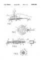
- FIG. 1illustrates schematically in what way an injection chamber device, also referred to as drip gate, is applied.
- the injection chamber device 1is implanted under a patient's skin 2 and via a catheter 3 fluids are supplied vascularly, derospinally or to a body cavity.
- the injection chamber device 1may be secured to a layer of muscular tissue 6 by means of a plurality of sutures 5.
- the injection chamber devicecomprises a chamber 7, which in operation is filled with the fluid to be administered to the patient.
- a wall 9 of, for instance, silicone rubberwhich wall can be pierced by means of a hollow needle 8, for instance that of a syringe.
- FIGS. 2 and 3show that the catheter has been slid into a tube 10.
- the tube 10is made of pliable material and in turn secured in a bore 12 through the wall of the injection chamber 1.
- a hollow plug 11may be used for this purpose, which plug is slid into the tube 11 from the side of chamber 7, the wall of the tube thus being wedged between the plug 11 and the wall of the bore 12.
- the tube 10,which may, for instance, be made of silicone rubber, extends from the chamber 7 through the wall 14 of the device and through a first member 15 of the connecting means.
- the member 15is an integral part of the chamber wall 14.
- the member 15may also be a separate member, which may optionally be disposed at some distance from the chamber wall, as is also shown in FIG. 4.
- the member 15is provided with a longitudinal bore through which the tube 10 extends. At least a part 18 of the longitudinal bore 17, which part is at an end of the member 15, tightly surrounds the tube 10. As shown in FIG. 4, this part may advantageously have a relatively small wall thickness in relation to the rest of the member 15 and is further provided with a plurality of longitudinal slots 19. As shown in FIG. 5, the embodiment shown is provided with four longitudinal slots 19.
- the tubecan be locally constricted to some extent, thus holding down the catheter 3 it contains.
- a second member 21is provided.
- the memberis a tubular sliding sleeve and can be fitted so tightly over the part 18 of the member 15, as is indicated in FIG. 4 by an arrow 22, that the tongues 20 are squeezed against and into the wall of the tube 10.
- the sliding sleeve 21could, for instance, have an internal wall that is tapered at least in part.
- the sliding sleeve 21has an internal annular shoulder 23, which can snap into an annular circumferential groove 24 of the part 18 of the member 15, but has an internal diameter that is slightly smaller than that of the circumferential groove when the tongues are in the inoperative position. If the sleeve is secured in the clamped position in a different manner, the circumferential groove need not unconditionally be provided.
- the sliding sleevemay advantageously be provided with a second annular shoulder 25, which in operation engages behind a shoulder provided beyond the tongues 20 or in a groove provided in the first member beyond the tongues 20.
- FIG. 4shows such a shoulder at 26.
- the shoulder 26is preferably disposed in such a way that it permits the sleeve to be shifted over part 18 between a clamping position (shown in FIG. 3) and an uncoupling position without the connection between the first and the second members being broken.
- the tongues 20are not squeezed and the catheter can be shifted in the tube 10 or be removed from it.
- the sleevetherefore, can already be mounted on the first member during manufacture, which reduces the risk of the sleeve being lost.
- the sleeveis further provided with a plurality of circumferential grooves 26 which facilitate handling the sleeve.
- Shifting the sleeve between the clamping position and the uncoupling positionis then effected by rotating the sleeve relatively to the part 18 in the manner of a nut.
- the sleevemay be internally threaded to cooperate with screwthread on the part 18 and the sleeve may be provided with a narrower part Capable of squeezing the tongues.
- the shoulders 23 and 25may optionally comprise a plurality of annularly disposed projections.
Landscapes
- Health & Medical Sciences (AREA)
- Heart & Thoracic Surgery (AREA)
- Pulmonology (AREA)
- Engineering & Computer Science (AREA)
- Anesthesiology (AREA)
- Biomedical Technology (AREA)
- Hematology (AREA)
- Life Sciences & Earth Sciences (AREA)
- Animal Behavior & Ethology (AREA)
- General Health & Medical Sciences (AREA)
- Public Health (AREA)
- Veterinary Medicine (AREA)
- Infusion, Injection, And Reservoir Apparatuses (AREA)
- Soil Working Implements (AREA)
- Surgical Instruments (AREA)
- Media Introduction/Drainage Providing Device (AREA)
Abstract
Description
The invention relates to an implantable injection chamber device comprising a housing which encloses an injection chamber and has at least one wall that can be pierced with a hollow needle, and a bore provided in a wall of the chamber, there being further provided connecting means for connecting a catheter to the bore.
A similar injection chamber device is known per se from practice and serves to facilitate the prolonged or frequent administration of medicines. The injection chamber device is intended to be implanted close under the patient's skin, with the pierceable wall turned towards the skin. By means of a needle, which is introduced through the skin and the special pierceable wall, a medicine is injected into the injection chamber. From the injection chamber the medicine can be supplied vascularly or derospinally or to a body cavity via a catheter. The pierceable wall is a silicone membrane, which closes again after removal of the needle. The needle may for instance be a hypodermic needle with a syringe for intermittent administration or, for instance, a needle connected to an infusion device (a so-called drip) or a pump for continuous administration.
Since the injection chamber device is implanted subcutaneously it is of great importance that the connection with the catheter can reliably and easily be made. According to the prior art to make the connection between the injection chamber and a catheter, a metal tube is used which is connected to the injection chamber device, links up with the bore in the chamber wall, and is connected to a catheter by means of a metal or synthetic plastics clamp which is pinched fast.
A drawback of the device according to the prior art is that squeezing with pincers will cause a deformation of the metal or synthetic plastics clamp that is not entirely within one's control, so that one cannot always be sure that the connection has actually been made in the way intended. Furthermore, the catheter and/or the tube may be damaged when the clamp is pinched tight. Further, the outlet tube of the chamber may perforate the catheter during the subcutaneous implantation.
The present invention aims to overcome the drawbacks outlined above and generally to provide an injection chamber device which can safely and simply be connected to a catheter.
To this effect an implantable injection chamber device of the kind described above is characterized according to the present invention in that the connecting means comprise a tube of pliable material which is connected to the bore and in operation extends through a bore in a first member of the connecting means, at least a part of said first member surrounding the tube relatively tightly and said part being provided with a plurality of radially distributed longitudinal grooves; and that a second member of the connecting means is provided, which in operation surrounds the part of the first member that is provided with longitudinal grooves and is capable of pressing inwardly the parts of the first member between the longitudinal grooves.
The invention will now be further described, by way of example, with reference to the accompanying drawings, in which
FIG. 1 schematically illustrates in what way an injection chamber device is applied;
FIG. 2 schematically shows a top plan view of an example of a device according to the invention;
FIG. 3 schematically shows a part-sectional view of an embodiment of a device according to the invention;
FIG. 4 schematically shows a cross-sectional exploded view of an example of a device according to the invention; and
FIG. 5 shows in end view one of the members of the connecting means of FIG. 4.
FIG. 1 illustrates schematically in what way an injection chamber device, also referred to as drip gate, is applied. Theinjection chamber device 1 is implanted under a patient'sskin 2 and via acatheter 3 fluids are supplied vascularly, derospinally or to a body cavity. Theinjection chamber device 1 may be secured to a layer ofmuscular tissue 6 by means of a plurality ofsutures 5. The injection chamber device comprises a chamber 7, which in operation is filled with the fluid to be administered to the patient. To that effect there is provided awall 9 of, for instance, silicone rubber, which wall can be pierced by means of ahollow needle 8, for instance that of a syringe.
An example of an injection chamber device according to the invention is schematically shown in top plan view in FIG. 2 and partly in cross-section in FIG. 3. FIGS. 2 and 3 show that the catheter has been slid into atube 10. Thetube 10 is made of pliable material and in turn secured in abore 12 through the wall of theinjection chamber 1. As shown in FIG. 3, ahollow plug 11 may be used for this purpose, which plug is slid into thetube 11 from the side of chamber 7, the wall of the tube thus being wedged between theplug 11 and the wall of thebore 12. Thetube 10, which may, for instance, be made of silicone rubber, extends from the chamber 7 through thewall 14 of the device and through afirst member 15 of the connecting means. In the embodiment shown in FIGS. 2 and 3 themember 15 is an integral part of thechamber wall 14. As is shown in FIG. 4 themember 15 may also be a separate member, which may optionally be disposed at some distance from the chamber wall, as is also shown in FIG. 4.
Themember 15 is provided with a longitudinal bore through which thetube 10 extends. At least apart 18 of thelongitudinal bore 17, which part is at an end of themember 15, tightly surrounds thetube 10. As shown in FIG. 4, this part may advantageously have a relatively small wall thickness in relation to the rest of themember 15 and is further provided with a plurality oflongitudinal slots 19. As shown in FIG. 5, the embodiment shown is provided with fourlongitudinal slots 19.
By providing the longitudinal slots, in fact four cylindrically arrangedresilient tongues 20 are created, which to some extent can be bent towards each other to bring a radial compressive force to bear on thetube 10.
By means of thetongues 20, therefore, the tube can be locally constricted to some extent, thus holding down thecatheter 3 it contains.
To move thetongues 20 inwardly asecond member 21 is provided. The member is a tubular sliding sleeve and can be fitted so tightly over thepart 18 of themember 15, as is indicated in FIG. 4 by anarrow 22, that thetongues 20 are squeezed against and into the wall of thetube 10.
To this effect thesliding sleeve 21 could, for instance, have an internal wall that is tapered at least in part. In the embodiment shown thesliding sleeve 21 has an internalannular shoulder 23, which can snap into an annularcircumferential groove 24 of thepart 18 of themember 15, but has an internal diameter that is slightly smaller than that of the circumferential groove when the tongues are in the inoperative position. If the sleeve is secured in the clamped position in a different manner, the circumferential groove need not unconditionally be provided.
The sliding sleeve may advantageously be provided with a secondannular shoulder 25, which in operation engages behind a shoulder provided beyond thetongues 20 or in a groove provided in the first member beyond thetongues 20.
FIG. 4 shows such a shoulder at 26. Theshoulder 26 is preferably disposed in such a way that it permits the sleeve to be shifted overpart 18 between a clamping position (shown in FIG. 3) and an uncoupling position without the connection between the first and the second members being broken.
In the uncoupling position thetongues 20 are not squeezed and the catheter can be shifted in thetube 10 or be removed from it.
The sleeve, therefore, can already be mounted on the first member during manufacture, which reduces the risk of the sleeve being lost.
In the embodiment shown the sleeve is further provided with a plurality ofcircumferential grooves 26 which facilitate handling the sleeve.
It is noted that after reading the above various modifications of the embodiments described will readily occur to a person skilled in the art. Reference has already been made to the possibility of optionally forming the first member as an integral part of thechamber wall 14. A further possibility is to use a threaded sleeve instead of a sliding sleeve.
Shifting the sleeve between the clamping position and the uncoupling position is then effected by rotating the sleeve relatively to thepart 18 in the manner of a nut. To this effect the sleeve may be internally threaded to cooperate with screwthread on thepart 18 and the sleeve may be provided with a narrower part Capable of squeezing the tongues.
It is also possible to use a so-called bayonet joint, where the sleeve has a few inner projections, which in the clamping position fit into a recess of thepart 18. To shift the sleeve from the uncoupling position to the clamping position it must first be shifted linearly and then turned. During this turning movement the sleeve may be moved further up thepart 18 if the inner projections are moved along ascending shoulders on thepart 18.
Further it is needless to say that instead of 4, a different number of tongues may be used.
Theshoulders
These and similar modifications are considered to fall within the scope of the invention.
Claims (16)
1. An implantable injection chamber device comprising a housing which encloses an injection chamber and has at least one wall that can be pierced with a hollow needle, and a bore provided in a wall of the chamber, there being further provided connecting means for connecting a catheter to the bore, characterized in that the connecting means comprise a tube of pliable material which is connected to the bore and in operation extends through a bore in a first member of the connecting means, at least a part of said first member surrounding the tube relatively tightly and said part being provided with a plurality of radially disposed longitudinal grooves; and that a second member of the connecting means is provided, which in operation surrounds the part of the first member that is provided with longitudinal grooves and is capable of pressing inwardly the parts of the first member between the longitudinal grooves.
2. An implantable injection chamber device according to claim 1, characterized in that said longitudinal grooves of said first member extend from one end thereof to form resilient tongues between said longitudinal grooves.
3. An implantable injection chamber device according to claim 2, characterized in that said second member is a sleeve in operation surrounding said tongues and which presses said tongues inwardly.
4. An implantable injection chamber device according to claim 3, characterized in that said sleeve is internally tapered.
5. An implantable injection device according to claim 3, characterized in that the sleeve comprises first internal annular shoulder means.
6. An implantable injection chamber device according to claim 5, characterized in that the first member comprises an annular groove provided near the tongues, said groove in operation seating the shoulder of the sleeve.
7. An implantable injection chamber device according to claim 3, characterized in that the sleeve is a sliding sleeve.
8. An implantable injection chamber device according to claim 3, characterized in that the sleeve is a threaded sleeve.
9. An implantable injection chamber device according to claim 3, characterized in that the sleeve has second internal shoulder means, which in operation engage behind a corresponding shoulder of the first member.
10. An implantable injection chamber device according to claim 9, characterized in that the second internal shoulder means of the sleeve and the corresponding shoulder of the first member permit the sleeve to be displaced between a clamping position and an uncoupling position without the shoulders passing each other.
11. An implantable injection chamber device according to claim 1, characterized in that the first member forms an integral part of the housing.
12. An implantable injection chamber device according to claim 1, characterized in that the tube is clamped tight in the bore in the chamber wall by means of a bored plug.
13. An implantable injection chamber device according to claim 1, characterized in that the second member is provided with external grooves and/or ribs.
14. An implantable injection chamber device according to claim 1, characterized in that the second member can be coupled to the first member by means of a bayonet joint.
15. An implantable injection chamber device according to claim 14, characterized in that the sleeve is provided with one or more internal projections, which cooperate with ascending shoulders in the first member.
16. A connecting arrangement for connecting an injection chamber with a catheter, which comprises first and second cooperating members according to claim 1.
Applications Claiming Priority (2)
| Application Number | Priority Date | Filing Date | Title |
|---|---|---|---|
| NL8802577 | 1988-10-19 | ||
| NL8802577ANL8802577A (en) | 1988-10-19 | 1988-10-19 | IMPLANTABLE INJECTION ROOM DEVICE. |
Publications (1)
| Publication Number | Publication Date |
|---|---|
| US5026344Atrue US5026344A (en) | 1991-06-25 |
Family
ID=19853086
Family Applications (1)
| Application Number | Title | Priority Date | Filing Date |
|---|---|---|---|
| US07/452,789Expired - Fee RelatedUS5026344A (en) | 1988-10-19 | 1989-12-19 | Implantable injection chamber device |
Country Status (5)
| Country | Link |
|---|---|
| US (1) | US5026344A (en) |
| EP (1) | EP0368377B1 (en) |
| AT (1) | ATE80320T1 (en) |
| DE (1) | DE68902808T2 (en) |
| NL (1) | NL8802577A (en) |
Cited By (50)
| Publication number | Priority date | Publication date | Assignee | Title |
|---|---|---|---|---|
| US5176653A (en)* | 1990-02-15 | 1993-01-05 | Joel Metals | Improvements to implantable vascular access devices |
| WO1994005351A1 (en)* | 1992-09-04 | 1994-03-17 | Ensminger William D | Implantable access devices |
| US5318545A (en)* | 1991-09-06 | 1994-06-07 | Device Labs, Inc. | Composite implantable biocompatible vascular access port device |
| US5387192A (en)* | 1994-01-24 | 1995-02-07 | Sims Deltec, Inc. | Hybrid portal and method |
| US5399168A (en)* | 1991-08-29 | 1995-03-21 | C. R. Bard, Inc. | Implantable plural fluid cavity port |
| US5405325A (en)* | 1991-10-17 | 1995-04-11 | Labs; Joseph D. | Access graft |
| US5417656A (en)* | 1990-03-01 | 1995-05-23 | Michigan Transtech Corporation | Implantable access devices |
| US5458631A (en)* | 1989-01-06 | 1995-10-17 | Xavier; Ravi | Implantable catheter with electrical pulse nerve stimulators and drug delivery system |
| US5520632A (en)* | 1991-04-11 | 1996-05-28 | Robert Leveen | Ascites valve |
| US5520643A (en)* | 1990-03-01 | 1996-05-28 | Michigan Transtech Corporation | Implantable access devices |
| US5562618A (en)* | 1994-01-21 | 1996-10-08 | Sims Deltec, Inc. | Portal assembly and catheter connector |
| US5637102A (en)* | 1995-05-24 | 1997-06-10 | C. R. Bard, Inc. | Dual-type catheter connection system |
| US5647855A (en)* | 1992-05-06 | 1997-07-15 | Trooskin; Stanley Z. | Self-healing diaphragm in a subcutaneous infusion port |
| US5792104A (en)* | 1996-12-10 | 1998-08-11 | Medtronic, Inc. | Dual-reservoir vascular access port |
| US5830172A (en)* | 1991-04-11 | 1998-11-03 | Leveen; Harry H. | Ascites valve |
| USD413672S (en) | 1997-03-27 | 1999-09-07 | Hudson Design Group | Implantable injection port |
| US5989216A (en)* | 1995-06-29 | 1999-11-23 | Sims Deltec, Inc. | Access portal and method |
| US6003906A (en)* | 1997-11-04 | 1999-12-21 | Terence M. Fogarty | Connector for elastomeric conduit |
| US6039712A (en)* | 1997-11-04 | 2000-03-21 | Terence M. Fogarty | Implantable injection port |
| US6113572A (en)* | 1995-05-24 | 2000-09-05 | C. R. Bard, Inc. | Multiple-type catheter connection systems |
| US6213973B1 (en)* | 1998-01-12 | 2001-04-10 | C. R. Bard, Inc. | Vascular access port with elongated septum |
| US6221064B1 (en)* | 1998-07-27 | 2001-04-24 | B. Braun Celsa | Tube coupling device for connecting a tubular rigid stem to a flexible catheter tube |
| US6468252B1 (en)* | 2000-08-03 | 2002-10-22 | Sanfilippo, Ii Dominic J. | Clamp for vascular access device |
| US6478783B1 (en) | 2000-05-26 | 2002-11-12 | H. Robert Moorehead | Anti-sludge medication ports and related methods |
| US20040254537A1 (en)* | 2003-06-16 | 2004-12-16 | Conlon Sean P. | Subcutaneous self attaching injection port with integral moveable retention members |
| US20050283118A1 (en)* | 2003-12-19 | 2005-12-22 | Joshua Uth | Implantable medical device with simulataneous attachment mechanism and method |
| US20060127165A1 (en)* | 2002-02-05 | 2006-06-15 | C. R. Bard, Inc. | Connection methods |
| US20060293626A1 (en)* | 2005-06-24 | 2006-12-28 | Byrum Randal T | Applier for implantable medical device |
| US20060293628A1 (en)* | 2005-06-24 | 2006-12-28 | Hunt John V | Implantable medical device with indicator |
| US20070010790A1 (en)* | 2005-06-24 | 2007-01-11 | Byrum Randal T | Injection port |
| US20070149947A1 (en)* | 2003-12-19 | 2007-06-28 | Byrum Randal T | Audible and tactile feedback |
| US20090234272A1 (en)* | 2006-05-15 | 2009-09-17 | Gilbert Schiltges | Infusion set with a massage-hub |
| US20100234808A1 (en)* | 2003-06-16 | 2010-09-16 | Uth Joshua R | Injection Port Applier with Downward Force Actuation |
| US8398654B2 (en) | 2008-04-17 | 2013-03-19 | Allergan, Inc. | Implantable access port device and attachment system |
| US8409221B2 (en) | 2008-04-17 | 2013-04-02 | Allergan, Inc. | Implantable access port device having a safety cap |
| US8506532B2 (en) | 2009-08-26 | 2013-08-13 | Allergan, Inc. | System including access port and applicator tool |
| US8708979B2 (en) | 2009-08-26 | 2014-04-29 | Apollo Endosurgery, Inc. | Implantable coupling device |
| US8715158B2 (en) | 2009-08-26 | 2014-05-06 | Apollo Endosurgery, Inc. | Implantable bottom exit port |
| US8801597B2 (en) | 2011-08-25 | 2014-08-12 | Apollo Endosurgery, Inc. | Implantable access port with mesh attachment rivets |
| US8821373B2 (en) | 2011-05-10 | 2014-09-02 | Apollo Endosurgery, Inc. | Directionless (orientation independent) needle injection port |
| US8858421B2 (en) | 2011-11-15 | 2014-10-14 | Apollo Endosurgery, Inc. | Interior needle stick guard stems for tubes |
| US8882728B2 (en) | 2010-02-10 | 2014-11-11 | Apollo Endosurgery, Inc. | Implantable injection port |
| US8882655B2 (en) | 2010-09-14 | 2014-11-11 | Apollo Endosurgery, Inc. | Implantable access port system |
| US8905916B2 (en) | 2010-08-16 | 2014-12-09 | Apollo Endosurgery, Inc. | Implantable access port system |
| US8992415B2 (en) | 2010-04-30 | 2015-03-31 | Apollo Endosurgery, Inc. | Implantable device to protect tubing from puncture |
| US9089395B2 (en) | 2011-11-16 | 2015-07-28 | Appolo Endosurgery, Inc. | Pre-loaded septum for use with an access port |
| US9125718B2 (en) | 2010-04-30 | 2015-09-08 | Apollo Endosurgery, Inc. | Electronically enhanced access port for a fluid filled implant |
| US9192501B2 (en) | 2010-04-30 | 2015-11-24 | Apollo Endosurgery, Inc. | Remotely powered remotely adjustable gastric band system |
| US9199069B2 (en) | 2011-10-20 | 2015-12-01 | Apollo Endosurgery, Inc. | Implantable injection port |
| US10406274B1 (en) | 2017-06-02 | 2019-09-10 | Jose Ramirez | Accessing assembly for hemodialysis administration |
Families Citing this family (5)
| Publication number | Priority date | Publication date | Assignee | Title |
|---|---|---|---|---|
| US5380301A (en)* | 1992-07-10 | 1995-01-10 | Sherwood Medical Company | Catheter/hub strain relief and method of manufacture thereof |
| FR2703593B1 (en)* | 1993-04-09 | 1995-05-24 | Celsa Lg | Connection device and assembly for flexible catheter. |
| FR2753382B1 (en)* | 1996-09-18 | 1999-01-08 | Vermed | INTERCHANGEABLE CATHETER CONNECTION DEVICE FOR INTERCHANGEABLE CHAMBERS |
| US6074379A (en)* | 1998-03-06 | 2000-06-13 | Sherwood Services Ag | Catheter strain relief device |
| US20070025181A1 (en) | 2003-06-03 | 2007-02-01 | Mixpac Systems Ag | Device for connecting a tubule to a mixer |
Citations (9)
| Publication number | Priority date | Publication date | Assignee | Title |
|---|---|---|---|---|
| GB891392A (en)* | 1958-03-14 | 1962-03-14 | Martin James | A new or improved connector for releasably and fluid-tightly coupling conduits |
| GB2020385A (en)* | 1978-05-03 | 1979-11-14 | Festo Maschf Stoll G | Fluid supply line connector |
| US4398910A (en)* | 1981-02-26 | 1983-08-16 | Blake L W | Wound drain catheter |
| EP0091773A2 (en)* | 1982-04-12 | 1983-10-19 | Gerhard Siegfried Eric Schmidt | Coupling for pressure hose |
| US4652255A (en)* | 1983-10-28 | 1987-03-24 | Miguel Martinez | Irrigating and aspirating handpiece for use in ophthalmic surgery |
| EP0258580A2 (en)* | 1986-08-21 | 1988-03-09 | B. Braun Melsungen AG | Implantable catheter device |
| FR2612784A1 (en)* | 1987-03-23 | 1988-09-30 | Ela Medical Sa | Improvements to implantable apparatus for diffusing chemotherapeutic products into the body |
| US4781680A (en)* | 1987-03-02 | 1988-11-01 | Vir Engineering | Resealable injection site |
| US4955861A (en)* | 1988-04-21 | 1990-09-11 | Therex Corp. | Dual access infusion and monitoring system |
- 1988
- 1988-10-19NLNL8802577Apatent/NL8802577A/ennot_activeApplication Discontinuation
- 1989
- 1989-10-19EPEP89202649Apatent/EP0368377B1/ennot_activeExpired - Lifetime
- 1989-10-19ATAT89202649Tpatent/ATE80320T1/ennot_activeIP Right Cessation
- 1989-10-19DEDE8989202649Tpatent/DE68902808T2/ennot_activeExpired - Fee Related
- 1989-12-19USUS07/452,789patent/US5026344A/ennot_activeExpired - Fee Related
Patent Citations (9)
| Publication number | Priority date | Publication date | Assignee | Title |
|---|---|---|---|---|
| GB891392A (en)* | 1958-03-14 | 1962-03-14 | Martin James | A new or improved connector for releasably and fluid-tightly coupling conduits |
| GB2020385A (en)* | 1978-05-03 | 1979-11-14 | Festo Maschf Stoll G | Fluid supply line connector |
| US4398910A (en)* | 1981-02-26 | 1983-08-16 | Blake L W | Wound drain catheter |
| EP0091773A2 (en)* | 1982-04-12 | 1983-10-19 | Gerhard Siegfried Eric Schmidt | Coupling for pressure hose |
| US4652255A (en)* | 1983-10-28 | 1987-03-24 | Miguel Martinez | Irrigating and aspirating handpiece for use in ophthalmic surgery |
| EP0258580A2 (en)* | 1986-08-21 | 1988-03-09 | B. Braun Melsungen AG | Implantable catheter device |
| US4781680A (en)* | 1987-03-02 | 1988-11-01 | Vir Engineering | Resealable injection site |
| FR2612784A1 (en)* | 1987-03-23 | 1988-09-30 | Ela Medical Sa | Improvements to implantable apparatus for diffusing chemotherapeutic products into the body |
| US4955861A (en)* | 1988-04-21 | 1990-09-11 | Therex Corp. | Dual access infusion and monitoring system |
Cited By (89)
| Publication number | Priority date | Publication date | Assignee | Title |
|---|---|---|---|---|
| US5458631A (en)* | 1989-01-06 | 1995-10-17 | Xavier; Ravi | Implantable catheter with electrical pulse nerve stimulators and drug delivery system |
| US5176653A (en)* | 1990-02-15 | 1993-01-05 | Joel Metals | Improvements to implantable vascular access devices |
| US5542923A (en)* | 1990-03-01 | 1996-08-06 | Michigan Transtech Corporation | Implantable access devices |
| US5554117A (en)* | 1990-03-01 | 1996-09-10 | Michigan Transtech Corporation | Implantable access devices |
| US5607393A (en)* | 1990-03-01 | 1997-03-04 | Michigan Transtech Corporation | Implantable access devices |
| US5556381A (en)* | 1990-03-01 | 1996-09-17 | The Michigan Transtech Corporation | Implantable access devices |
| US5417656A (en)* | 1990-03-01 | 1995-05-23 | Michigan Transtech Corporation | Implantable access devices |
| US5792123A (en)* | 1990-03-01 | 1998-08-11 | Michigan Transtech Corporation | Implantable access devices |
| US5503630A (en)* | 1990-03-01 | 1996-04-02 | Michigan Transtech Corporation | Inplantable access devices |
| US5531684A (en)* | 1990-03-01 | 1996-07-02 | Michigan Transtech Corporation | Implantable access devices |
| US5520643A (en)* | 1990-03-01 | 1996-05-28 | Michigan Transtech Corporation | Implantable access devices |
| US5527278A (en)* | 1990-03-01 | 1996-06-18 | Michigan Transtech Corporation | Implantable access devices |
| US5527277A (en)* | 1990-03-01 | 1996-06-18 | Michigan Transtech Corporation | Implantable access devices |
| US5520632A (en)* | 1991-04-11 | 1996-05-28 | Robert Leveen | Ascites valve |
| US5830172A (en)* | 1991-04-11 | 1998-11-03 | Leveen; Harry H. | Ascites valve |
| US5399168A (en)* | 1991-08-29 | 1995-03-21 | C. R. Bard, Inc. | Implantable plural fluid cavity port |
| US5318545A (en)* | 1991-09-06 | 1994-06-07 | Device Labs, Inc. | Composite implantable biocompatible vascular access port device |
| US5405325A (en)* | 1991-10-17 | 1995-04-11 | Labs; Joseph D. | Access graft |
| US5647855A (en)* | 1992-05-06 | 1997-07-15 | Trooskin; Stanley Z. | Self-healing diaphragm in a subcutaneous infusion port |
| WO1994005351A1 (en)* | 1992-09-04 | 1994-03-17 | Ensminger William D | Implantable access devices |
| US5632729A (en)* | 1994-01-21 | 1997-05-27 | Sims Deltec, Inc. | Catheter connector |
| US5613945A (en)* | 1994-01-21 | 1997-03-25 | Sims Deltec, Inc. | Portal assembly |
| US5743873A (en)* | 1994-01-21 | 1998-04-28 | Sims Deltec, Inc. | Methods for using catheter connectors and portals, and methods of assembly |
| US5562618A (en)* | 1994-01-21 | 1996-10-08 | Sims Deltec, Inc. | Portal assembly and catheter connector |
| US5558641A (en)* | 1994-01-24 | 1996-09-24 | Sims Deltec, Inc. | Hybrid portal and method |
| US5387192A (en)* | 1994-01-24 | 1995-02-07 | Sims Deltec, Inc. | Hybrid portal and method |
| US5637102A (en)* | 1995-05-24 | 1997-06-10 | C. R. Bard, Inc. | Dual-type catheter connection system |
| US6113572A (en)* | 1995-05-24 | 2000-09-05 | C. R. Bard, Inc. | Multiple-type catheter connection systems |
| US5989216A (en)* | 1995-06-29 | 1999-11-23 | Sims Deltec, Inc. | Access portal and method |
| US5792104A (en)* | 1996-12-10 | 1998-08-11 | Medtronic, Inc. | Dual-reservoir vascular access port |
| USD413672S (en) | 1997-03-27 | 1999-09-07 | Hudson Design Group | Implantable injection port |
| US6003906A (en)* | 1997-11-04 | 1999-12-21 | Terence M. Fogarty | Connector for elastomeric conduit |
| US6039712A (en)* | 1997-11-04 | 2000-03-21 | Terence M. Fogarty | Implantable injection port |
| US6213973B1 (en)* | 1998-01-12 | 2001-04-10 | C. R. Bard, Inc. | Vascular access port with elongated septum |
| US6221064B1 (en)* | 1998-07-27 | 2001-04-24 | B. Braun Celsa | Tube coupling device for connecting a tubular rigid stem to a flexible catheter tube |
| US6478783B1 (en) | 2000-05-26 | 2002-11-12 | H. Robert Moorehead | Anti-sludge medication ports and related methods |
| US6468252B1 (en)* | 2000-08-03 | 2002-10-22 | Sanfilippo, Ii Dominic J. | Clamp for vascular access device |
| US20060127165A1 (en)* | 2002-02-05 | 2006-06-15 | C. R. Bard, Inc. | Connection methods |
| US8226632B2 (en)* | 2002-02-05 | 2012-07-24 | C. R. Bard, Inc. | Connection methods |
| US20100217199A1 (en)* | 2003-06-16 | 2010-08-26 | Ethicon Endo-Surgery, Inc. | Method of Repositioning an Injection Port |
| US7862546B2 (en) | 2003-06-16 | 2011-01-04 | Ethicon Endo-Surgery, Inc. | Subcutaneous self attaching injection port with integral moveable retention members |
| US8007474B2 (en) | 2003-06-16 | 2011-08-30 | Ethicon Endo-Surgery, Inc. | Implantable medical device with reversible attachment mechanism and method |
| US20110082426A1 (en)* | 2003-06-16 | 2011-04-07 | Ethicon Endo-Surgery, Inc. | Subcutaneous self attaching injection port with integral moveable retention members |
| US8864717B2 (en) | 2003-06-16 | 2014-10-21 | Ethicon Endo-Surgery, Inc. | Subcutaneous self attaching injection port with integral moveable retention members |
| US8211127B2 (en) | 2003-06-16 | 2012-07-03 | Ethicon Endo-Surgery, Inc. | Injection port with extendable and retractable fasteners |
| US8764713B2 (en) | 2003-06-16 | 2014-07-01 | Ethicon Endo-Surgery, Inc. | Method of repositioning an injection port |
| US20040254537A1 (en)* | 2003-06-16 | 2004-12-16 | Conlon Sean P. | Subcutaneous self attaching injection port with integral moveable retention members |
| US20100234808A1 (en)* | 2003-06-16 | 2010-09-16 | Uth Joshua R | Injection Port Applier with Downward Force Actuation |
| US8758303B2 (en) | 2003-06-16 | 2014-06-24 | Ethicon Endo-Surgery, Inc. | Injection port with applier |
| US8715243B2 (en) | 2003-06-16 | 2014-05-06 | Ethicon Endo-Surgery, Inc. | Injection port applier with downward force actuation |
| US20050283119A1 (en)* | 2003-06-16 | 2005-12-22 | Joshua Uth | Implantable medical device with reversible attachment mechanism and method |
| US20100130941A1 (en)* | 2003-06-16 | 2010-05-27 | Conlon Sean P | Audible And Tactile Feedback |
| US20100211085A1 (en)* | 2003-06-16 | 2010-08-19 | Ethicon Endo-Surgery, Inc. | Injection Port with Extendable and Retractable Fasteners |
| US20050283118A1 (en)* | 2003-12-19 | 2005-12-22 | Joshua Uth | Implantable medical device with simulataneous attachment mechanism and method |
| US7553298B2 (en) | 2003-12-19 | 2009-06-30 | Ethicon Endo-Surgery, Inc. | Implantable medical device with cover and method |
| US7850660B2 (en) | 2003-12-19 | 2010-12-14 | Ethicon Endo-Surgery, Inc. | Implantable medical device with simultaneous attachment mechanism and method |
| US20070149947A1 (en)* | 2003-12-19 | 2007-06-28 | Byrum Randal T | Audible and tactile feedback |
| US8162897B2 (en) | 2003-12-19 | 2012-04-24 | Ethicon Endo-Surgery, Inc. | Audible and tactile feedback |
| US20060293627A1 (en)* | 2003-12-19 | 2006-12-28 | Byrum Randal T | Applier with safety for implantable medical device |
| US20060293625A1 (en)* | 2003-12-19 | 2006-12-28 | Hunt John V | Implantable medical device with cover and method |
| US8029477B2 (en) | 2003-12-19 | 2011-10-04 | Ethicon Endo-Surgery, Inc. | Applier with safety for implantable medical device |
| US20060293628A1 (en)* | 2005-06-24 | 2006-12-28 | Hunt John V | Implantable medical device with indicator |
| US20060293626A1 (en)* | 2005-06-24 | 2006-12-28 | Byrum Randal T | Applier for implantable medical device |
| US7651483B2 (en) | 2005-06-24 | 2010-01-26 | Ethicon Endo-Surgery, Inc. | Injection port |
| US7918844B2 (en) | 2005-06-24 | 2011-04-05 | Ethicon Endo-Surgery, Inc. | Applier for implantable medical device |
| US7561916B2 (en) | 2005-06-24 | 2009-07-14 | Ethicon Endo-Surgery, Inc. | Implantable medical device with indicator |
| US20070010790A1 (en)* | 2005-06-24 | 2007-01-11 | Byrum Randal T | Injection port |
| US9084848B2 (en)* | 2006-05-15 | 2015-07-21 | Roche Diagnostics International Ag | Infusion set with a massage-hub |
| US20090234272A1 (en)* | 2006-05-15 | 2009-09-17 | Gilbert Schiltges | Infusion set with a massage-hub |
| US8398654B2 (en) | 2008-04-17 | 2013-03-19 | Allergan, Inc. | Implantable access port device and attachment system |
| US8409221B2 (en) | 2008-04-17 | 2013-04-02 | Allergan, Inc. | Implantable access port device having a safety cap |
| US9023062B2 (en) | 2008-04-17 | 2015-05-05 | Apollo Endosurgery, Inc. | Implantable access port device and attachment system |
| US9023063B2 (en) | 2008-04-17 | 2015-05-05 | Apollo Endosurgery, Inc. | Implantable access port device having a safety cap |
| US8715158B2 (en) | 2009-08-26 | 2014-05-06 | Apollo Endosurgery, Inc. | Implantable bottom exit port |
| US8708979B2 (en) | 2009-08-26 | 2014-04-29 | Apollo Endosurgery, Inc. | Implantable coupling device |
| US8506532B2 (en) | 2009-08-26 | 2013-08-13 | Allergan, Inc. | System including access port and applicator tool |
| US8882728B2 (en) | 2010-02-10 | 2014-11-11 | Apollo Endosurgery, Inc. | Implantable injection port |
| US9125718B2 (en) | 2010-04-30 | 2015-09-08 | Apollo Endosurgery, Inc. | Electronically enhanced access port for a fluid filled implant |
| US8992415B2 (en) | 2010-04-30 | 2015-03-31 | Apollo Endosurgery, Inc. | Implantable device to protect tubing from puncture |
| US9241819B2 (en) | 2010-04-30 | 2016-01-26 | Apollo Endosurgery, Inc. | Implantable device to protect tubing from puncture |
| US9192501B2 (en) | 2010-04-30 | 2015-11-24 | Apollo Endosurgery, Inc. | Remotely powered remotely adjustable gastric band system |
| US8905916B2 (en) | 2010-08-16 | 2014-12-09 | Apollo Endosurgery, Inc. | Implantable access port system |
| US8882655B2 (en) | 2010-09-14 | 2014-11-11 | Apollo Endosurgery, Inc. | Implantable access port system |
| US8821373B2 (en) | 2011-05-10 | 2014-09-02 | Apollo Endosurgery, Inc. | Directionless (orientation independent) needle injection port |
| US8801597B2 (en) | 2011-08-25 | 2014-08-12 | Apollo Endosurgery, Inc. | Implantable access port with mesh attachment rivets |
| US9199069B2 (en) | 2011-10-20 | 2015-12-01 | Apollo Endosurgery, Inc. | Implantable injection port |
| US8858421B2 (en) | 2011-11-15 | 2014-10-14 | Apollo Endosurgery, Inc. | Interior needle stick guard stems for tubes |
| US9089395B2 (en) | 2011-11-16 | 2015-07-28 | Appolo Endosurgery, Inc. | Pre-loaded septum for use with an access port |
| US10406274B1 (en) | 2017-06-02 | 2019-09-10 | Jose Ramirez | Accessing assembly for hemodialysis administration |
Also Published As
| Publication number | Publication date |
|---|---|
| EP0368377A1 (en) | 1990-05-16 |
| DE68902808T2 (en) | 1993-02-04 |
| DE68902808D1 (en) | 1992-10-15 |
| EP0368377B1 (en) | 1992-09-09 |
| NL8802577A (en) | 1990-05-16 |
| ATE80320T1 (en) | 1992-09-15 |
Similar Documents
| Publication | Publication Date | Title |
|---|---|---|
| US5026344A (en) | Implantable injection chamber device | |
| EP0873757B1 (en) | Cannula sealing shield assembly | |
| CA1164753A (en) | Injection-syringe | |
| US4704103A (en) | Implantable catheter means | |
| EP0238005B1 (en) | High viscosity fluid delivery system | |
| EP1549367B1 (en) | Flush syringe having compressible plunger | |
| US3344785A (en) | Valve for exchange transfusion system | |
| US5465938A (en) | Universal fluid flow control | |
| US5453097A (en) | Control of fluid flow | |
| EP0635278B1 (en) | - Self-aspirating syringe or cartridge having an aspirating plunger | |
| US8142403B2 (en) | Syringe assembly with plunger having a secondary dispensing reservoir | |
| US4445896A (en) | Catheter plug | |
| US5178609A (en) | Medical liquid injector for continuous transfusion | |
| US5273533A (en) | Medical valve | |
| US4369781A (en) | Luer connector | |
| EP0888794B1 (en) | Method for filling syringes | |
| US6221064B1 (en) | Tube coupling device for connecting a tubular rigid stem to a flexible catheter tube | |
| JP2530100B2 (en) | Hypodermic syringe | |
| US4581024A (en) | Needle assembly | |
| EP0827760A2 (en) | Catheter adapter assembly | |
| US6491668B1 (en) | Needleless fluid transfer | |
| US6245041B1 (en) | Fluid dispenser with fill adapter | |
| EP0516762A4 (en) | Locking y-connector for selective attachment to exterior of medical tubing | |
| AU2019300986B2 (en) | Needle hub and syringe arrangement | |
| JPH02185261A (en) | Syringe |
Legal Events
| Date | Code | Title | Description |
|---|---|---|---|
| REMI | Maintenance fee reminder mailed | ||
| FPAY | Fee payment | Year of fee payment:4 | |
| SULP | Surcharge for late payment | ||
| REMI | Maintenance fee reminder mailed | ||
| LAPS | Lapse for failure to pay maintenance fees | ||
| FP | Lapsed due to failure to pay maintenance fee | Effective date:19990625 | |
| STCH | Information on status: patent discontinuation | Free format text:PATENT EXPIRED DUE TO NONPAYMENT OF MAINTENANCE FEES UNDER 37 CFR 1.362 |