US5025445A - System for, and method of, regulating the wavelength of a light beam - Google Patents
System for, and method of, regulating the wavelength of a light beamDownload PDFInfo
- Publication number
- US5025445A US5025445AUS07/440,605US44060589AUS5025445AUS 5025445 AUS5025445 AUS 5025445AUS 44060589 AUS44060589 AUS 44060589AUS 5025445 AUS5025445 AUS 5025445A
- Authority
- US
- United States
- Prior art keywords
- light
- laser
- wavelength
- detectors
- signals
- Prior art date
- Legal status (The legal status is an assumption and is not a legal conclusion. Google has not performed a legal analysis and makes no representation as to the accuracy of the status listed.)
- Expired - Lifetime
Links
- 238000000034methodMethods0.000titledescription15
- 230000001105regulatory effectEffects0.000titledescription8
- 230000003287optical effectEffects0.000abstractdescription41
- 238000012545processingMethods0.000abstractdescription13
- 230000003595spectral effectEffects0.000abstractdescription11
- 230000001419dependent effectEffects0.000abstractdescription6
- 230000002596correlated effectEffects0.000abstractdescription2
- 230000026676system processEffects0.000abstractdescription2
- 239000000463materialSubstances0.000description21
- BJQHLKABXJIVAM-UHFFFAOYSA-Nbis(2-ethylhexyl) phthalateChemical compoundCCCCC(CC)COC(=O)C1=CC=CC=C1C(=O)OCC(CC)CCCCBJQHLKABXJIVAM-UHFFFAOYSA-N0.000description17
- 230000000873masking effectEffects0.000description12
- 230000000875corresponding effectEffects0.000description5
- 238000004519manufacturing processMethods0.000description5
- 230000002411adverseEffects0.000description4
- 239000004020conductorSubstances0.000description4
- 230000001131transforming effectEffects0.000description3
- IJGRMHOSHXDMSA-UHFFFAOYSA-NAtomic nitrogenChemical compoundN#NIJGRMHOSHXDMSA-UHFFFAOYSA-N0.000description2
- XAGFODPZIPBFFR-UHFFFAOYSA-NaluminiumChemical compound[Al]XAGFODPZIPBFFR-UHFFFAOYSA-N0.000description2
- 229910052782aluminiumInorganic materials0.000description2
- 238000005530etchingMethods0.000description2
- 125000006850spacer groupChemical group0.000description2
- 239000000758substrateSubstances0.000description2
- 239000006094ZerodurSubstances0.000description1
- 238000010521absorption reactionMethods0.000description1
- 239000002253acidSubstances0.000description1
- 239000000654additiveSubstances0.000description1
- 230000000996additive effectEffects0.000description1
- 239000011248coating agentSubstances0.000description1
- 238000000576coating methodMethods0.000description1
- 238000007596consolidation processMethods0.000description1
- 238000010276constructionMethods0.000description1
- 238000012937correctionMethods0.000description1
- 230000003247decreasing effectEffects0.000description1
- 238000013461designMethods0.000description1
- 238000001514detection methodMethods0.000description1
- 239000003989dielectric materialSubstances0.000description1
- 238000010292electrical insulationMethods0.000description1
- 238000009434installationMethods0.000description1
- 230000007774longtermEffects0.000description1
- 229910052757nitrogenInorganic materials0.000description1
- 230000000750progressive effectEffects0.000description1
- 239000010453quartzSubstances0.000description1
- 230000003252repetitive effectEffects0.000description1
- 230000010076replicationEffects0.000description1
- 239000012858resilient materialSubstances0.000description1
- 239000004065semiconductorSubstances0.000description1
- 230000035939shockEffects0.000description1
- 229910052710siliconInorganic materials0.000description1
- 239000010703siliconSubstances0.000description1
- VYPSYNLAJGMNEJ-UHFFFAOYSA-Nsilicon dioxideInorganic materialsO=[Si]=OVYPSYNLAJGMNEJ-UHFFFAOYSA-N0.000description1
Images


Classifications
- H—ELECTRICITY
- H01—ELECTRIC ELEMENTS
- H01S—DEVICES USING THE PROCESS OF LIGHT AMPLIFICATION BY STIMULATED EMISSION OF RADIATION [LASER] TO AMPLIFY OR GENERATE LIGHT; DEVICES USING STIMULATED EMISSION OF ELECTROMAGNETIC RADIATION IN WAVE RANGES OTHER THAN OPTICAL
- H01S3/00—Lasers, i.e. devices using stimulated emission of electromagnetic radiation in the infrared, visible or ultraviolet wave range
- H01S3/10—Controlling the intensity, frequency, phase, polarisation or direction of the emitted radiation, e.g. switching, gating, modulating or demodulating
- H01S3/13—Stabilisation of laser output parameters, e.g. frequency or amplitude
Definitions
- This inventionrelates to systems for regulating the wavelength of light as from a laser. More particularly, this invention relates to a system which is operative in real time to produce an indication, without any ambiguities, of the wavelength of the light as from a laser and which is responsive to such indication to adjust the wavelength of the light as from the laser to a particular value. The invention also relates to a method of regulating the light as from a laser in real time at a particular value.
- Integrated circuit chipsare being produced in ever increasing volumes for use in all kinds of electrical equipment and digital computers and data processing systems.
- the integrated circuit chipsare produced from dies which are disposed in a repetitive pattern on a wafer. Tens, and sometimes even hundreds, of such dies may be disposed on a wafer.
- each waferhas to be processed precisely because an error in the processing of one die on a wafer may be repeated in the processing of other dies on the wafer. This precise processing is particularly important because the value represented by the different dies on a wafer may be in the thousands, and even tens of thousands, of dollars.
- Each die on a waferis formed from a plurality of layers. Each layer is formed in a precise pattern, generally quite complex. Some of these layers are formed from electrical material to represent electrical circuitry. Others of these layers are formed from dielectric material to provide electrical insulation between the electrically conductive layers. An error in the processing, or an imprecise processing, of any one of the layers on a die may result in a die which does not meet the specifications established for the die.
- a substantially uniform coating of a particular materialmay be deposited on a substrate formed from a base material such as silicon or on a material previously deposited on the substrate.
- a substantially uniform materialwhen it is electrically conductive, it may be formed from a suitable material such as aluminum.
- the aluminumis then covered with a thin and substantially uniform layer of a masking material.
- the maskis constructed to pass light in a spatial pattern corresponding to the spatial pattern desired for the electrically conductive material in the layer.
- the light passing to the layerhardens the masking material.
- An etching materialsuch as an acid is then applied to the electrically conductive material.
- the etching materialetches the electrically conductive material at the positions where the masking material has not been hardened. In this way, the electrically conductive material remains in the layer only at the positions where the masking material has been hardened.
- the hardened masking materialis then washed from the layer to provide the desired pattern on this layer of the chip.
- the light applied through the mask to the masking material on the electrically conductive layerhas to be precisely controlled.
- lasersare used. Lasers are desirable because they provide substantially monochromatic light at high power levels.
- the lasers usedhave been excimer lasers in the ultraviolet range. For example, excimer lasers with a wavelength of approximately 248 nm have been, and are being, employed to harden a layer of masking material in a particular pattern. These lasers are tunable over a relatively narrow range of wavelengths.
- the wavelength of the light from the laserbe closely regulated to about 1 part per million. This results from the fact that changes in the wavelength of the light from the laser adversely affect the focussing of the light at the surface of the masking layer. This adversely affects the sharpness of the pattern in which the masking material is hardened. It accordingly adversely affects the sharpness of the pattern of the electrical circuitry produced in the electrically conductive layer covered by the masking material. This in turn adversely affects the electrical characteristics of the electrical circuitry.
- excimer lasersare generally pulsed at a particular repetition rate, such as approximately two hundred (200) pulses per second. It would be desirable to adjust the wavelength of the laser pulses in real time and in a time shorter than the time between pulses so that the wavelength of the light in each pulse is substantially a particular value such as approximately 248 nm. Furthermore, it would be desirable to provide this adjustment in a manner such that the wavelength of the laser light in each pulse is detected without any ambiguity in the detection. Until now, no one has provided a regulating system with the characteristics discussed above.
- This inventionprovides a system which meets the objectives discussed above.
- the systemmeasures the wavelength of each light pulse from a laser, even at a repetition rate as high as 200 pulses per second or even higher, and adjusts the wavelength of the light in the next pulse from the laser toward a particular value such as 248.000 nanometers.
- This wavelength valuecan be set to match with any particular lens design, or altitude of stepper installation.
- the wavelengthcan also be changed or slewed during a single exposure if desired.
- the systemoperates in real time and without any ambiguities.
- the system of this inventionis able to operate over a large range of wavelengths without any adjustment.
- the systemis not affected by changes in atmospheric temperature or pressure.
- the systemoperates to sample the light from the complete cross-section of the laser beam so as to enhance the accuracy in the regulation of the wavelength of the light from the laser.
- the systemprovides this regulation by providing a compact optical path which enhances the dimensional stability of the system and results in excellent long-term precision and stability.
- a laser light beamis processed in a first optical path to produce light indications in a plurality of free spectral paths. These light indications are introduced through slits to produce signals at spaced positions at the opposite peripheries of a linear detector array. The distances between correlated pairs of energized detectors at the opposite peripheries of the array indicate the relative value of the laser wavelength to high accuracy, but with an inherent additive ambiguity equal to an integer times a constant factor related to the optical system.
- the laser light beamis also processed in a second optical path simultaneously with the processing of the laser light beam in the first optical path.
- the second optical pathis dependent upon the wavelength of the laser light beam.
- the light produced in the second optical pathmay be introduced through another slit to energize centrally disposed detectors in the array.
- the particular detectors energizedare dependent upon the wavelength of the laser light.
- the "coarse" wavelength information derived from the second optical pathis used to remove the ambiguities in the wavelength information derived from the first optical path. Because there are no ambiguities, the laser wavelength can be calibrated to an absolute wavelength reference anywhere under the laser gain profile, and then slewed to the chosen operating wavelength. For example, even the normal carboninduced absorption line at approximately 247.856 nm could be used for such calibration.
- the detectors in the linear arraymay be scanned to produce signals related in time to the disposition of the detectors energized in the array.
- a data processing systemprocesses these signals and produces a signal to adjust the wavelength of the laser beam to a particular value.
- the system described abovemay operate in real time after each pulse to adjust the laser before the next pulse to produce light at the particular wavelength.
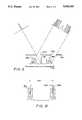
- FIG. 1is a plan view schematically illustrating an optical system included in one embodiment of this invention to determine the wavelength of a light beam from a laser;
- FIG. 2is a perspective view illustrating the disposition of the laser relative to certain components in the optical system shown in FIG. 1;
- FIG. 3is a view schematically illustrating the construction of an etalon assembly included in the optical system shown in FIG. 1;
- FIG. 4is a schematic view of a grating and a mirror included in the optical system shown in FIG. 1;
- FIG. 5is a schematic view, primarily in block form, of an electrical system which is operative in conjunction with the optical system of FIG. 1 to determine and regulate the wavelength of the light beam from the laser;
- FIG. 6is a schematic view illustrating the relative disposition of optical rings of light produced by the optical system of FIG. 1;
- FIG. 7illustrate the relative pattern of signals produced by the optical rings shown in FIG. 6;
- FIG. 8schematically illustrates another signal produced by the optical system of FIG. 1 to provide a coarse indication of the wavelength of the light beam from the laser;
- FIG. 9is a schematic view of a mask and an array of detectors for obtaining the production of a pattern of signals by the detectors in accordance with the processing of light from the laser by the optical system shown in FIG. 1;
- FIG. 10schematically illustrates how the electrical system shown in FIG. 5 processes the signals shown schematically in FIG. 9;
- FIG. 11schematically illustrates the pattern of signals passing through a comparator included in the electrical system shown in FIG. 5;
- FIG. 12schematically illustrates how the positions of the rings shown in FIG. 5 becomes shifted with changes in the wavelength o the light from the laser;
- FIG. 13illustrates the portions of the optical rings shown in FIG. 6 that can be consolidated by including another etalon assembly in the optical system of FIG. 1 instead of a grating as in the embodiment shown in FIG. 1;
- FIG. 14illustrates the optical pattern after the portions shown in FIG. 13 have been optically consolidated
- FIG. 15schematically illustrates a prism for providing the optical consolidation shown in FIGS. 13 and 14.
- a systemfor regulating the wavelength of light from a laser 10.
- the laseris typically pulsed at a suitable repetition rate such as approximately two hundred (200) pulses per second. While the particular embodiment of this invention is for a pulsed laser, the invention will work equally well on a laser operating on a continuous basis.
- the laserprovides monochromatic light at high power levels.
- the laseris an excimer laser which operates at a suitable wavelength of approximately two hundred and forty eight nanometers (248.000 nm).
- the system of the inventionincludes an optical sub-system shown schematically in FIG. 1 and an electronic sub-system shown primarily in block form in FIG. 5.
- the optical system in FIG. 1may be considered to be a plan view with the laser disposed below the plane of the paper and pointed vertically upwardly toward a primary splitter assembly 12.
- the splitter assembly 12is shown in FIG. 1 as being disposed at an angle to the laser 10.
- the beam splitter 12(also shown in FIG. 2) is disposed in an opening 14 and may be formed from a coated or uncoated quartz plate.
- the beam splitter 12is constructed to pass a large portion (approximately 95%) of the light from the laser 10 to a target such as a semi-conductor wafer (not shown). However, a relatively small fraction (approximately 5%) of the light directed by the laser 10 to the beam splitter 12 is reflected by the beam splitter to another beam splitter 16.
- the beam splitter 16may be constructed in a manner similar to that described above for the beam splitter 12.
- the beam splitter 16splits the light into two (2) paths. One of these paths is indicated in dot-and-dash lines at 18 and the other path is indicated in broken lines at 20.
- the optical path in the dot-and-dash lines 18provides a fine control over the amplitude wavelength of light from the laser 10 and the optical path shown in broken lines at 20 in FIG. 1 provides a coarse control over such wavelength.
- Signalsare produced from the light in each of the optical paths 18 and 20 by the electrical system shown in FIG. 5. These signals are processed by the electrical system shown in FIG. 5 to obtain the production of a control signal for regulating the wavelength of the light from the laser 10.
- the light passing in the path 18 through the beam splitter 16is reflected by a mirror 22 to a lens 24 which operates to focus the light.
- the lightthen passes through a diffuser 26 (FIGS. 1 and 3) to an etalon assembly generally indicated at 28.
- the etalon assembly 28may include a pair of members having highly reflective surfaces 30a and 30b the surfaces 30a and 30b are separated by a spacer 32 made from a suitable material such as Zero-Dur providing a low coefficient of thermal expansion.
- the members providing the reflective surfaces 30a and 30bare separated by a suitable dielectric such as air or vacuum.
- the members with the highly reflective surfaces 30a and 30bare mounted on supports 34 made from a suitably resilient material such as rubber to absorb mechanical shocks and vibrations.
- the diffuser 26, the members providing the reflective surfaces 30a and 30b, the spacer 32 and the supports 34may be disposed in a housing 36 filled with a vacuum or a suitably inert material such as nitrogen. In this way, the etalon assembly 28 is not affected by atmospheric changes in temperature and pressure.
- a Fourier transforming lens 40may also be disposed in the housing 36.
- the diffuser 26spatially and angularly mixes the light from the lens 24 to uniformly sample the entire laser light beam from the standpoint of beam wavelength and line width content.
- the diffused lightis then sampled in the etalon assembly 28 to provide a reflection of light back and forth between the highly polished surfaces 30a and 30b.
- the light from the etalon assembly 28then passes to the Fourier transforming lens 40, which transforms the light from the etalon assembly 28 to produce concentric rings 42 (FIG. 6) in a pattern in which ring widths are proportional to spectral line width and the diameters provide information relating to wavelength and wavelength stability.
- the successive ones of the concentric rings 42may be considered to be separated from one another by a wavelength which may be defined a the free spectral range or the etalon.
- the progressive pairs of rings 42are spaced from a central position by progressively decreasing distances as shown schematically in FIG. 6.
- the light from the lens 40passes to a mirror 46 which reflects the light to a mirror 48.
- the light reflected from the mirror 48in turn passes through a pair of spaced and narrow slits 50a and 50b in a mask 52 (FIG. 9).
- the light passing through the slits 50a and 50bis then introduced to a shield 54 which blocks the passage of stray light and limits the passage of light only to the light passing through the slits 50a and 50b.
- the lightthen falls on a linear array of optical detectors 56 (FIGS. 1 and 9) to produce signals 58a and 58b (FIG. 7) at the optical detectors in accordance with the pattern of the spectral rings 42.
- the signals 58a and 58bare produced at the opposite peripheries of the linear array of the optical detectors 56.
- the distance of the signals 58a and 58b from the center of the detector arraymay vary depending upon several factors. One of these factors may result from variations in the position of the surfaces 30a and 30b in the etalon assembly 28 as a result of movement of the supporting rubber pads 34. Another of these factors may result from other mechanical or thermal drifts in the optical components which provide the optical path 18. As will be seen subsequently, however, these variations may be accommodated by the system constituting this invention so that they do not affect the wavelength indications provided by the system.
- a relatively small portion of the light passing to the beam splitter 16is reflected into the optical path 20 to a mask 60 having a slit 62.
- the light passing through the slit 62travels to a mirror 64 which reflects the light to a mirror 66.
- the mirrorin turn reflects the light back to the mirror 64 for reflection to a coarse diagnostic assembly generally indicated at 68 in FIGS. 1 and 4.
- the coarse diagnostic assembly 68(FIGS. 1 and 4) includes a lens 70 which collimates the light originating from the slit 62 and introduces the collimated light to a grating 72.
- the grating 72acts to reflect the incoming light in different directions depending upon the frequency of the light. Each direction represents a different color component or different wavelength.
- the grating 72is constructed, and is disposed at a particular angle, so that the light at a wavelength of approximately 248 nm is reflected by the grating back to the mirror 64. As the light travels from the grating 72 through the lens 70 to the mirror 64, the lens acts to focus the light.
- the light passing through the lens 70 in the path 20is reflected by the mirror 64 to a mirror 76 which in turn reflects the light to the mask 52.
- the lightpasses through the slit 50a in the mask 52 to the shield 54, which acts to block the passage of stray light.
- the lightthen falls on the linear array of detectors 56.
- the lightproduces a single pulse of light 78 at a central position in the linear array of the detectors 56.
- the positions of the particular detectors 56 producing the signal 78are dependent upon the wavelength of the light from the laser 10.
- the signal 78 produced by the detectors 56is indicated in solid lines in FIG. 8. Broken lines to the left and right of the signal 78 in FIG. 8 indicate changes in the wavelength above and below the value represented by the signal 78 in solid lines.
- the electrical system shown in block form in FIG. 5processes the signals 58a and 58b and the signal 78 to indicate the wavelength of the light from the laser 10.
- the system shown in FIG. 5includes a video clock 80 which may be constructed in a conventional manner.
- the video clock 80synchronizes the scanning of the detectors 56 at a video rate by a scanner 82 to obtain the production of output signals by the scanner at times dependent upon the occurrence of the signals 58a and 58b and the signal 78 in the array. These times may be indicated by a pixel counter 83 which counts the clock signals from the video clock 80.
- the signals produced from the light pulses 58a and 58b and the signal 78are introduced to a sample and hold circuit 84 to obtain the production of the particular one of the signals 58a with the peak amplitude and to obtain the holding of this peak amplitude in the circuit 84.
- the amplitude of the signal held in the circuit 84is divided by two (2) in a circuit 86 to produce a resultant signal 88 (FIG. 11) which is held in a circuit 90.
- the circuits 84, 86 and 90may be constructed in a conventional manner to operate on an analog or digital basis.
- the signal 88 held in the circuit 90(FIG. 5) is introduced to a comparator 92 which also receives the signals 58a and 58b and the signal 78.
- the comparator 92compares the amplitude of the signal 88 with the amplitudes of the signals 58a and 58b and the signal 78 to produce signals 94a, 94b and 94c (FIG. 11) representing the portions of the signals 58a and 58b and the signal 78 with amplitudes greater than the amplitude of the signal 88.
- the signals 94a, 94b and 94c (FIG. 11) from the comparator 92 (FIG. 5)are introduced to a data processing system such as a microprocessor 96.
- the microprocessor 96compares corresponding pairs of the signals 94a and 94b to determine the pair which has the greatest correlation from a time standpoint relative to a central position in the array of the detectors 56. For example, the outermost one of the signals 94a is compared with the outermost one of the signals 94b relative to the central position in the array of the detectors 56 to determine the time correlation between the two signals. As another example, similar time correlation is determined between the innermost ones of the signals 94a and 94b.
- the microprocessor 96selects the pair of signals with the greatest correlation in time relative to a central position in the array of the detectors 56. For example, the microprocessor 96 may select a related pair of signals 98a and 98b. The microprocessor then determines the wavelengths of the selected pair of signals 98a and 98b (FIG. 10) at the outer ends of each of these signals and at the inner ends of the signals. This is indicated schematically in FIG. 10 by the distances 100 and 102.
- the microprocessor 96operates in conjunction with a pixel counter 83 which provides at each instant a count of the detectors 56 being processed in the linear array at each instant.
- the wavelengths of the signalscan be determined since the positions of the detectors 56 in the array are related to wavelengths.
- the microprocessor 96then processes the wavelengths (represented by the distances 100 and 102 in FIG. 10) on an independent basis and averages the output from the processing to determine a resultant mean wavelength. This wavelength would be a precise indication of the resultant mean wavelength of the light from the laser 10 if there were no ambiguities. However, since the signals 94a and 94b represent a plurality of free spectral ranges as indicated by the rings 42 in FIG. 6, there is an ambiguity if the particular one of the free spectral ranges is not known.
- An alternative techniquewould be to calculate the diameter corresponding to a target wavelength. The processor would then adjust the laser incrementally to produce the required average of diameters.
- the feedbackis performed in terms of wavelength to provide greater diagnostic information and faster connection algorithms. For example, both incremental and estimated total error correction can be performed between pulses. In addition, accurate real time slewing can be performed and the target wavelengths can be adjusted at any time.
- signals 52a and 58bare produced to represent a wavelength of 248.000 nm.
- the signals 58a and 58bare shifted in position as shown in FIG. 12b, the signals are produced from light from the laser 10 at a wavelength of 248.000 nm.
- a further shift in the position of the signals 58a and 58bcauses the signals in FIG. 12c to coincide with the signals 58a and 58b in FIG. 12a.
- the signals 58a and 58b in FIG. 12care produced from light from the laser 10 at a wavelength of 248.000 nm.
- the wavelength interval between exact replications of the signals 58a and 58bis called the free spectral range of the etalon assembly 28.
- the free spectral range (FSR)is 0.020 nm.
- Further shifts in the signals 58 a and 58b to the position in FIG. 12bmay represent wavelengths at 248.030, 248.050, etc. nm and further shifts in the signals 58a and 58b to the position shown in FIG. 12c represent wavelengths at 248.040, 248.060, etc. nm.
- the signals 94a and 94bmay be also processed by the microprocessor 96 to determine the width of the beam of light from the laser 10. To determine this, the microprocessor 96 processes the wavelengths at the outer ends of the selected pair of signals 94a and 94b (represented by the distance 100 in FIG. 10) to obtain a first result and also processes the wavelengths at the inner ends of the signals 94a and 94b (represented by the distance 102 in FIG. 10) to obtain a second result. The microprocessor 96 then processes the first and second results on a subtractive basis to determine the thickness of the beam of light from the laser 10.
- the microprocessor 96also processes the signal 94c (FIG. 11) to determine the particular one of the free spectral ranges in which the wavelength of the light from the laser 10 is being produced.
- the microprocessor 96determines this by determining the position of the signal 94c in the array of detectors 56. By providing this coarse indication, the microprocessor 96 resolves any ambiguities in the signals 94a and 94b.
- the resultant signal from the microprocessor 96indicates the wavelength of the light from the microprocessor on a precise and unambiguous basis.
- the microprocessorthen processes the desired wavelength (e.g. 248.000 nm) of the light from the laser 10 and the resultant signal representing the actual wavelength of the light from the laser 10 to determine the change which should be made in the operating characteristics of the laser to correct the wavelength to the desired value such as 248.000 nm. This determination is represented by signals on a line 104 (FIG. 5) from the microprocessor 96.
- desired wavelengthe.g. 248.000 nm
- the signals from the microprocessor 96are introduced through the line 104 to the laser 10 to change to the wavelength of light from the laser to the particular value such as 248.000 nm.
- the adjustment in the wavelength of the light from the laseris made after each pulse from the laser and before the production of the next pulse from the laser.
- the wavelength of the pulses of light from the laser 10is regulated on a real time basis at the particular value such as 248.000 nm, and high speed real time diagnostic information of wavelength and linewidth is made available.
- the system and method described abovehave certain important advantages. They provide a precise regulation of the wavelength of the light from the laser 10 in real time without any ambiguities. The system and method are able to provide this regulation over a wide range of wavelengths without any adjustment. The system and method provide this regulation by operating upon the entire cross-section of the light beam from the laser 10. The system is disposed in a compact area relative to the laser 10 so as not to interfere with the operation of the laser. The system and method are not affected by changes in external parameters such as changes in atmospheric temperature and pressure.
- an etalon assemblymay be used.
- the etalon assemblymay correspond to the assembly 28 shown in FIGS. 1 and 3 and described in detail above.
- One way of implementing such an etalon assemblymay be to use a firmly mounted etalon in a cell of constant temperature and pressure (corresponding to the housing 30 in FIG. 3) instead of mounting the etalon on resilient supports such as the supports 34 in FIG. 3.
- a single ring arcis provided in the center of the linear array formed by the detectors 56 to provide a coarse indication of the wavelength of the light from the laser 10.
- an etalon assemblymay be resiliently mounted as in the embodiment shown in FIG. 3 to provide spaced rings 42 as shown in FIG. 6.
- these ringswill not fit solely in the central portion of the detector array.
- a prism 114such as shown in FIG. 15 may be provided to retain only the ring portions 110 and 110b and to consolidate them into the portions 112a and 112b. The prism 114 acts to refract diverging light from the segments 110a and 110b and to collimate such light into the adjacent and interlocking patterns 112a and 112b.
Landscapes
- Physics & Mathematics (AREA)
- Electromagnetism (AREA)
- Engineering & Computer Science (AREA)
- Plasma & Fusion (AREA)
- Optics & Photonics (AREA)
- Lasers (AREA)
Abstract
Description
Claims (25)
Priority Applications (1)
| Application Number | Priority Date | Filing Date | Title |
|---|---|---|---|
| US07/440,605US5025445A (en) | 1989-11-22 | 1989-11-22 | System for, and method of, regulating the wavelength of a light beam |
Applications Claiming Priority (1)
| Application Number | Priority Date | Filing Date | Title |
|---|---|---|---|
| US07/440,605US5025445A (en) | 1989-11-22 | 1989-11-22 | System for, and method of, regulating the wavelength of a light beam |
Publications (1)
| Publication Number | Publication Date |
|---|---|
| US5025445Atrue US5025445A (en) | 1991-06-18 |
Family
ID=23749438
Family Applications (1)
| Application Number | Title | Priority Date | Filing Date |
|---|---|---|---|
| US07/440,605Expired - LifetimeUS5025445A (en) | 1989-11-22 | 1989-11-22 | System for, and method of, regulating the wavelength of a light beam |
Country Status (1)
| Country | Link |
|---|---|
| US (1) | US5025445A (en) |
Cited By (190)
| Publication number | Priority date | Publication date | Assignee | Title |
|---|---|---|---|---|
| US5420877A (en)* | 1993-07-16 | 1995-05-30 | Cymer Laser Technologies | Temperature compensation method and apparatus for wave meters and tunable lasers controlled thereby |
| US5440578A (en)* | 1993-07-16 | 1995-08-08 | Cymer Laser Technologies | Gas replenishment method and apparatus for excimer lasers |
| US5867514A (en)* | 1997-01-09 | 1999-02-02 | Cymer, Inc. | Laser wavelength control circuit having automatic DC offset and gain adjustment |
| US5978391A (en)* | 1997-07-18 | 1999-11-02 | Cymer, Inc. | Wavelength reference for excimer laser |
| US5978394A (en)* | 1998-03-11 | 1999-11-02 | Cymer, Inc. | Wavelength system for an excimer laser |
| US6078599A (en)* | 1997-07-22 | 2000-06-20 | Cymer, Inc. | Wavelength shift correction technique for a laser |
| EP0992093A4 (en)* | 1998-03-11 | 2000-07-05 | Cymer Inc | Wavelength system for an excimer laser |
| US6128323A (en)* | 1997-04-23 | 2000-10-03 | Cymer, Inc. | Reliable modular production quality narrow-band high REP rate excimer laser |
| US6160832A (en)* | 1998-06-01 | 2000-12-12 | Lambda Physik Gmbh | Method and apparatus for wavelength calibration |
| US6212217B1 (en)* | 1997-07-01 | 2001-04-03 | Cymer, Inc. | Smart laser with automated beam quality control |
| US6243170B1 (en) | 1999-02-04 | 2001-06-05 | Cymer, Inc. | Double pass etalon spectrometer |
| US6317448B1 (en) | 1999-09-23 | 2001-11-13 | Cymer, Inc. | Bandwidth estimating technique for narrow band laser |
| US6320663B1 (en) | 1999-01-22 | 2001-11-20 | Cymer, Inc. | Method and device for spectral measurements of laser beam |
| US6330261B1 (en) | 1997-07-18 | 2001-12-11 | Cymer, Inc. | Reliable, modular, production quality narrow-band high rep rate ArF excimer laser |
| US20020015430A1 (en)* | 2000-05-15 | 2002-02-07 | Lambda Physik Ag | Electrical excitation circuit for a pulsed gas laser |
| US6359693B2 (en) | 1999-02-04 | 2002-03-19 | Cymer, Inc. | Double pass double etalon spectrometer |
| US6381256B1 (en) | 1999-02-10 | 2002-04-30 | Lambda Physik Ag | Molecular fluorine laser with spectral linewidth of less than 1 pm |
| US6389052B2 (en) | 1999-03-17 | 2002-05-14 | Lambda Physik Ag | Laser gas replenishment method |
| US6421365B1 (en) | 1999-11-18 | 2002-07-16 | Lambda Physik Ag | Narrow band excimer or molecular fluorine laser having an output coupling interferometer |
| US6424666B1 (en) | 1999-06-23 | 2002-07-23 | Lambda Physik Ag | Line-narrowing module for high power laser |
| US6426966B1 (en) | 1999-02-10 | 2002-07-30 | Lambda Physik Ag | Molecular fluorine (F2) laser with narrow spectral linewidth |
| US20020105994A1 (en)* | 2000-11-17 | 2002-08-08 | Partlo William N. | Gas discharge laser with improved beam path |
| US6442181B1 (en) | 1998-07-18 | 2002-08-27 | Cymer, Inc. | Extreme repetition rate gas discharge laser |
| US20020127497A1 (en)* | 1998-09-10 | 2002-09-12 | Brown Daniel J. W. | Large diffraction grating for gas discharge laser |
| US6463086B1 (en)* | 1999-02-10 | 2002-10-08 | Lambda Physik Ag | Molecular fluorine laser with spectral linewidth of less than 1 pm |
| US6477193B2 (en) | 1998-07-18 | 2002-11-05 | Cymer, Inc. | Extreme repetition rate gas discharge laser with improved blower motor |
| US20020167986A1 (en)* | 2000-11-17 | 2002-11-14 | Xiaojiang Pan | Gas discharge ultraviolet laser with enclosed beam path with added oxidizer |
| US6490307B1 (en) | 1999-03-17 | 2002-12-03 | Lambda Physik Ag | Method and procedure to automatically stabilize excimer laser output parameters |
| US20030012234A1 (en)* | 2000-06-19 | 2003-01-16 | Watson Tom A. | Six to ten KHz, or greater gas discharge laser system |
| US6522681B1 (en) | 1999-04-26 | 2003-02-18 | Lambda Physik Ag | Laser for the generation of narrow band radiation |
| US6529531B1 (en) | 1997-07-22 | 2003-03-04 | Cymer, Inc. | Fast wavelength correction technique for a laser |
| US6532247B2 (en) | 2000-02-09 | 2003-03-11 | Cymer, Inc. | Laser wavelength control unit with piezoelectric driver |
| US6539046B2 (en)* | 1998-10-02 | 2003-03-25 | Cymer, Inc. | Wavemeter for gas discharge laser |
| US20030058429A1 (en)* | 2001-08-13 | 2003-03-27 | Lambda Physik Ag | Stable energy detector for extreme ultraviolet radiation detection |
| US6546037B2 (en) | 1999-02-10 | 2003-04-08 | Lambda Physik Ag | Molecular fluorine laser with spectral linewidth of less than 1 pm |
| US6553050B1 (en) | 1999-11-18 | 2003-04-22 | Lambda Physik Ag | Narrow band excimer or molecular fluorine laser having an output coupling interferometer |
| US6556600B2 (en) | 1999-09-27 | 2003-04-29 | Cymer, Inc. | Injection seeded F2 laser with centerline wavelength control |
| US6567450B2 (en) | 1999-12-10 | 2003-05-20 | Cymer, Inc. | Very narrow band, two chamber, high rep rate gas discharge laser system |
| US6577663B2 (en) | 2000-06-19 | 2003-06-10 | Lambda Physik Ag | Narrow bandwidth oscillator-amplifier system |
| US6580517B2 (en) | 2000-03-01 | 2003-06-17 | Lambda Physik Ag | Absolute wavelength calibration of lithography laser using multiple element or tandem see through hollow cathode lamp |
| US6590922B2 (en) | 1999-09-27 | 2003-07-08 | Cymer, Inc. | Injection seeded F2 laser with line selection and discrimination |
| US6597462B2 (en) | 2000-03-01 | 2003-07-22 | Lambda Physik Ag | Laser wavelength and bandwidth monitor |
| US6603788B1 (en) | 1999-11-23 | 2003-08-05 | Lambda Physik Ag | Resonator for single line selection |
| US6603789B1 (en) | 2000-07-05 | 2003-08-05 | Lambda Physik Ag | Narrow band excimer or molecular fluorine laser with improved beam parameters |
| US20030210715A1 (en)* | 1998-06-01 | 2003-11-13 | Lambda Physik Ag. | Absolute wavelength calibration of lithography laser using multiple element or tandem see through hollow cathode lamp |
| US20030219056A1 (en)* | 2001-01-29 | 2003-11-27 | Yager Thomas A. | High power deep ultraviolet laser with long life optics |
| US6667804B1 (en) | 1999-10-12 | 2003-12-23 | Lambda Physik Ag | Temperature compensation method for wavemeters |
| US6671294B2 (en) | 1997-07-22 | 2003-12-30 | Cymer, Inc. | Laser spectral engineering for lithographic process |
| US20040022291A1 (en)* | 2001-04-09 | 2004-02-05 | Das Plash P. | Lithography laser with beam delivery and beam pointing control |
| US6690704B2 (en) | 2001-04-09 | 2004-02-10 | Cymer, Inc. | Control system for a two chamber gas discharge laser |
| US6693939B2 (en) | 2001-01-29 | 2004-02-17 | Cymer, Inc. | Laser lithography light source with beam delivery |
| US6700915B2 (en) | 1999-03-12 | 2004-03-02 | Lambda Physik Ag | Narrow band excimer laser with a resonator containing an optical element for making wavefront corrections |
| US6704340B2 (en) | 2001-01-29 | 2004-03-09 | Cymer, Inc. | Lithography laser system with in-place alignment tool |
| US6704339B2 (en) | 2001-01-29 | 2004-03-09 | Cymer, Inc. | Lithography laser with beam delivery and beam pointing control |
| US20040047385A1 (en)* | 1999-12-10 | 2004-03-11 | Knowles David S. | Very narrow band, two chamber, high reprate gas discharge laser system |
| US20040047386A1 (en)* | 1998-07-18 | 2004-03-11 | Das Palash P. | High repetition rate gas discharge laser with precise pulse timing control |
| US20040057474A1 (en)* | 1997-07-22 | 2004-03-25 | Cymer, Inc. | Bandwidth control technique for a laser |
| US6714577B1 (en) | 1999-03-17 | 2004-03-30 | Lambda Physik Ag | Energy stabilized gas discharge laser |
| US6717973B2 (en) | 1999-02-10 | 2004-04-06 | Lambda Physik Ag | Wavelength and bandwidth monitor for excimer or molecular fluorine laser |
| US6721345B2 (en) | 2000-07-14 | 2004-04-13 | Lambda Physik Ag | Electrostatic precipitator corona discharge ignition voltage probe for gas status detection and control system for gas discharge lasers |
| US6727731B1 (en) | 1999-03-12 | 2004-04-27 | Lambda Physik Ag | Energy control for an excimer or molecular fluorine laser |
| US6735232B2 (en) | 2000-01-27 | 2004-05-11 | Lambda Physik Ag | Laser with versatile output energy |
| US20040105479A1 (en)* | 2002-05-07 | 2004-06-03 | Brian Klene | Laser lithography light source with beam delivery |
| US6747741B1 (en) | 2000-10-12 | 2004-06-08 | Lambda Physik Ag | Multiple-pass interferometric device |
| US6757316B2 (en) | 1999-12-27 | 2004-06-29 | Cymer, Inc. | Four KHz gas discharge laser |
| US20040136417A1 (en)* | 2002-05-07 | 2004-07-15 | Webb R. Kyle | Long delay and high TIS pulse stretcher |
| US6785316B1 (en) | 1999-08-17 | 2004-08-31 | Lambda Physik Ag | Excimer or molecular laser with optimized spectral purity |
| US20040174919A1 (en)* | 1999-05-10 | 2004-09-09 | Knowles David S. | Line selected F2 two chamber laser system |
| US20040179560A1 (en)* | 2001-01-29 | 2004-09-16 | Das Palash P. | Gas discharge laser light source beam delivery unit |
| US20040182838A1 (en)* | 2001-04-18 | 2004-09-23 | Das Palash P. | Very high energy, high stability gas discharge laser surface treatment system |
| US6798812B2 (en) | 2002-01-23 | 2004-09-28 | Cymer, Inc. | Two chamber F2 laser system with F2 pressure based line selection |
| US6801561B2 (en) | 2000-09-25 | 2004-10-05 | Lambda Physik Ag | Laser system and method for spectral narrowing through wavefront correction |
| US6807205B1 (en) | 2000-07-14 | 2004-10-19 | Lambda Physik Ag | Precise monitor etalon calibration technique |
| US6834066B2 (en) | 2000-04-18 | 2004-12-21 | Lambda Physik Ag | Stabilization technique for high repetition rate gas discharge lasers |
| US20050018739A1 (en)* | 2001-05-03 | 2005-01-27 | Ershov Alexander I. | Timing control for two-chamber gas discharge laser system |
| US20050025882A1 (en)* | 2001-01-29 | 2005-02-03 | Partlo William N. | Optical elements with protective undercoating |
| US6853653B2 (en) | 1997-07-22 | 2005-02-08 | Cymer, Inc. | Laser spectral engineering for lithographic process |
| US20050035103A1 (en)* | 2001-04-18 | 2005-02-17 | Partlo William N. | Laser thin film poly-silicon annealing optical system |
| US20050046856A1 (en)* | 2000-11-17 | 2005-03-03 | Rao Rajasekhar M. | Gas discharge mopa laser spectral analysis module |
| US6873418B1 (en) | 2003-09-30 | 2005-03-29 | Cymer, Inc. | Optical mountings for gas discharge MOPA laser spectral analysis module |
| US20050068538A1 (en)* | 2003-09-30 | 2005-03-31 | Rao Rajasekhar M. | Gas discharge mopa laser spectral analysis module |
| WO2005033625A1 (en)* | 2003-09-30 | 2005-04-14 | Cymer, Inc. | Gas discharge mopa laser spectral analysis module |
| US6882674B2 (en) | 1999-12-27 | 2005-04-19 | Cymer, Inc. | Four KHz gas discharge laser system |
| US20050094698A1 (en)* | 2003-01-31 | 2005-05-05 | Besaucele Herve A. | Multi-chambered excimer or molecular fluorine gas discharge laser fluorine injection control |
| US20050100072A1 (en)* | 2001-11-14 | 2005-05-12 | Rao Rajasekhar M. | High power laser output beam energy density reduction |
| US6907058B2 (en) | 2000-01-25 | 2005-06-14 | Lambda Physik Ag | Energy monitor for molecular fluorine laser |
| US20050135451A1 (en)* | 2003-07-30 | 2005-06-23 | Rule John A. | Method and apparatus for controlling the output of a gas discharge MOPA laser system |
| US20050141580A1 (en)* | 2001-04-18 | 2005-06-30 | Partlo William N. | Laser thin film poly-silicon annealing system |
| US20050185690A1 (en)* | 2003-12-18 | 2005-08-25 | Rule John A. | Method and apparatus for controlling the output of a gas discharge laser system |
| US20050226300A1 (en)* | 2004-03-31 | 2005-10-13 | Steiger Thomas D | Very high repetition rate narrow band gas discharge laser system |
| US20050226301A1 (en)* | 2004-03-31 | 2005-10-13 | Partlo William N | Gas discharge laser chamber improvements |
| US6963595B2 (en) | 2001-08-29 | 2005-11-08 | Cymer, Inc. | Automatic gas control system for a gas discharge laser |
| US20050259709A1 (en)* | 2002-05-07 | 2005-11-24 | Cymer, Inc. | Systems and methods for implementing an interaction between a laser shaped as a line beam and a film deposited on a substrate |
| US20050269529A1 (en)* | 2004-03-10 | 2005-12-08 | Cymer, Inc. | Systems and methods for reducing the influence of plasma-generated debris on the internal components of an EUV light source |
| US20050279946A1 (en)* | 2003-04-08 | 2005-12-22 | Cymer, Inc. | Systems and methods for deflecting plasma-generated ions to prevent the ions from reaching an internal component of an EUV light source |
| US20050286599A1 (en)* | 2004-06-29 | 2005-12-29 | Rafac Robert J | Method and apparatus for gas discharge laser output light coherency reduction |
| US20060001878A1 (en)* | 2003-04-29 | 2006-01-05 | Cymer, Inc. | Systems and methods for implementing an interaction between a laser shaped as a line beam and a film deposited on a substrate |
| US20060056478A1 (en)* | 1999-02-10 | 2006-03-16 | Hans-Stephen Albrecht | Laser gas replenishment method |
| US7039086B2 (en) | 2001-04-09 | 2006-05-02 | Cymer, Inc. | Control system for a two chamber gas discharge laser |
| US20060097203A1 (en)* | 2004-11-01 | 2006-05-11 | Cymer, Inc. | Systems and methods for cleaning a chamber window of an EUV light source |
| US20060146900A1 (en)* | 2001-08-29 | 2006-07-06 | Cymer, Inc. | Multi-chamber gas discharge laser bandwidth control through discharge timing |
| US7075963B2 (en) | 2000-01-27 | 2006-07-11 | Lambda Physik Ag | Tunable laser with stabilized grating |
| US7079564B2 (en) | 2001-04-09 | 2006-07-18 | Cymer, Inc. | Control system for a two chamber gas discharge laser |
| US7088758B2 (en) | 2001-07-27 | 2006-08-08 | Cymer, Inc. | Relax gas discharge laser lithography light source |
| US20060192152A1 (en)* | 2005-02-28 | 2006-08-31 | Cymer, Inc. | LPP EUV light source drive laser system |
| US20060192153A1 (en)* | 2005-02-25 | 2006-08-31 | Cymer, Inc. | Source material dispenser for EUV light source |
| US20060222034A1 (en)* | 2005-03-31 | 2006-10-05 | Cymer, Inc. | 6 Khz and above gas discharge laser system |
| US20060219957A1 (en)* | 2004-11-01 | 2006-10-05 | Cymer, Inc. | Laser produced plasma EUV light source |
| US20060249699A1 (en)* | 2004-03-10 | 2006-11-09 | Cymer, Inc. | Alternative fuels for EUV light source |
| US7141806B1 (en) | 2005-06-27 | 2006-11-28 | Cymer, Inc. | EUV light source collector erosion mitigation |
| US7154928B2 (en) | 2004-06-23 | 2006-12-26 | Cymer Inc. | Laser output beam wavefront splitter for bandwidth spectrum control |
| US20060291517A1 (en)* | 2005-06-27 | 2006-12-28 | Cymer, Inc. | High pulse repetition rate gas discharge laser |
| US20060289808A1 (en)* | 2005-06-27 | 2006-12-28 | Cymer, Inc. | Euv light source collector erosion mitigation |
| US20070001130A1 (en)* | 2005-06-29 | 2007-01-04 | Cymer, Inc. | LPP EUV plasma source material target delivery system |
| US20070001127A1 (en)* | 2005-06-30 | 2007-01-04 | Cymer, Inc. | Active bandwidth control for a laser |
| US20070001131A1 (en)* | 2005-06-29 | 2007-01-04 | Cymer, Inc. | LPP EUV light source drive laser system |
| US20070023711A1 (en)* | 2000-10-16 | 2007-02-01 | Fomenkov Igor V | Discharge produced plasma EUV light source |
| US20070023705A1 (en)* | 2005-06-27 | 2007-02-01 | Cymer, Inc. | EUV light source collector lifetime improvements |
| US20070071047A1 (en)* | 2005-09-29 | 2007-03-29 | Cymer, Inc. | 6K pulse repetition rate and above gas discharge laser system solid state pulse power system improvements |
| US20070071058A1 (en)* | 2005-09-29 | 2007-03-29 | Cymer, Inc. | Gas discharge laser system electrodes and power supply for delivering electrical energy to same |
| US20070096008A1 (en)* | 2005-10-28 | 2007-05-03 | Cymer, Inc. | Systems and methods to shape laser light as a homogeneous line beam for interaction with a film deposited on a substrate |
| US20070098033A1 (en)* | 2005-11-01 | 2007-05-03 | Cymer, Inc. | External optics and chamber support system |
| US20070102653A1 (en)* | 2005-11-05 | 2007-05-10 | Cymer, Inc. | EUV light source |
| US20070151957A1 (en)* | 2005-12-29 | 2007-07-05 | Honeywell International, Inc. | Hand-held laser welding wand nozzle assembly including laser and feeder extension tips |
| US7317536B2 (en) | 2005-06-27 | 2008-01-08 | Cymer, Inc. | Spectral bandwidth metrology for high repetition rate gas discharge lasers |
| US7394083B2 (en) | 2005-07-08 | 2008-07-01 | Cymer, Inc. | Systems and methods for EUV light source metrology |
| US20080179548A1 (en)* | 2003-04-08 | 2008-07-31 | Cymer, Inc. | Laser produced plasma EUV light source |
| US20090046295A1 (en)* | 2007-07-12 | 2009-02-19 | Volcano Corporation | Apparatus and methods for uniform sample clocking |
| US20090057567A1 (en)* | 2007-08-31 | 2009-03-05 | Cymer, Inc. | Gas management system for a laser-produced-plasma EUV light source |
| US20090092386A1 (en)* | 2007-10-05 | 2009-04-09 | Sony Corporation | Image pickup apparatus |
| US20090154642A1 (en)* | 2007-12-14 | 2009-06-18 | Cymer, Inc. | System managing gas flow between chambers of an extreme ultraviolet (EUV) photolithography apparatus |
| US20100032590A1 (en)* | 2008-08-06 | 2010-02-11 | Cymer, Inc. | Debris protection system having a magnetic field for an EUV light source |
| US7679029B2 (en) | 2005-10-28 | 2010-03-16 | Cymer, Inc. | Systems and methods to shape laser light as a line beam for interaction with a substrate having surface variations |
| US20100098122A1 (en)* | 2008-10-21 | 2010-04-22 | Jacques Robert N | Method and Apparatus for Laser Control in a Two Chamber Gas Discharge Laser |
| US20100098123A1 (en)* | 2008-10-21 | 2010-04-22 | Jacques Robert N | Method and apparatus for laser control in a two chamber gas discharge laser |
| US20100098124A1 (en)* | 2008-10-21 | 2010-04-22 | Jacques Robert N | Method and apparatus for laser control in a two chamber gas discharge laser |
| USRE41457E1 (en) | 1998-10-02 | 2010-07-27 | Cymer, Inc. | Wavemeter for gas discharge laser |
| US7856044B2 (en) | 1999-05-10 | 2010-12-21 | Cymer, Inc. | Extendable electrode for gas discharge laser |
| US8379687B2 (en) | 2005-06-30 | 2013-02-19 | Cymer, Inc. | Gas discharge laser line narrowing module |
| US8395781B2 (en) | 2007-07-12 | 2013-03-12 | Volcano Corporation | Automatic calibration systems and methods of use |
| US8629417B2 (en) | 2010-02-22 | 2014-01-14 | Gigaphoton Inc. | Extreme ultraviolet light generation apparatus |
| US9286673B2 (en) | 2012-10-05 | 2016-03-15 | Volcano Corporation | Systems for correcting distortions in a medical image and methods of use thereof |
| US9292918B2 (en) | 2012-10-05 | 2016-03-22 | Volcano Corporation | Methods and systems for transforming luminal images |
| US9301687B2 (en) | 2013-03-13 | 2016-04-05 | Volcano Corporation | System and method for OCT depth calibration |
| US9307926B2 (en) | 2012-10-05 | 2016-04-12 | Volcano Corporation | Automatic stent detection |
| US9324141B2 (en) | 2012-10-05 | 2016-04-26 | Volcano Corporation | Removal of A-scan streaking artifact |
| US9360630B2 (en) | 2011-08-31 | 2016-06-07 | Volcano Corporation | Optical-electrical rotary joint and methods of use |
| US9367965B2 (en) | 2012-10-05 | 2016-06-14 | Volcano Corporation | Systems and methods for generating images of tissue |
| US9383263B2 (en) | 2012-12-21 | 2016-07-05 | Volcano Corporation | Systems and methods for narrowing a wavelength emission of light |
| US9478940B2 (en) | 2012-10-05 | 2016-10-25 | Volcano Corporation | Systems and methods for amplifying light |
| US9486143B2 (en) | 2012-12-21 | 2016-11-08 | Volcano Corporation | Intravascular forward imaging device |
| US9596993B2 (en) | 2007-07-12 | 2017-03-21 | Volcano Corporation | Automatic calibration systems and methods of use |
| US9612105B2 (en) | 2012-12-21 | 2017-04-04 | Volcano Corporation | Polarization sensitive optical coherence tomography system |
| US9622706B2 (en) | 2007-07-12 | 2017-04-18 | Volcano Corporation | Catheter for in vivo imaging |
| US9709379B2 (en) | 2012-12-20 | 2017-07-18 | Volcano Corporation | Optical coherence tomography system that is reconfigurable between different imaging modes |
| US9730613B2 (en) | 2012-12-20 | 2017-08-15 | Volcano Corporation | Locating intravascular images |
| US9770172B2 (en) | 2013-03-07 | 2017-09-26 | Volcano Corporation | Multimodal segmentation in intravascular images |
| US9778108B2 (en) | 2015-05-22 | 2017-10-03 | Cymer, Llc | Metrology system and method having a plurality of sensors for estimating a spectral feature of a pulsed light beam |
| US9858668B2 (en) | 2012-10-05 | 2018-01-02 | Volcano Corporation | Guidewire artifact removal in images |
| US9867530B2 (en) | 2006-08-14 | 2018-01-16 | Volcano Corporation | Telescopic side port catheter device with imaging system and method for accessing side branch occlusions |
| US10012544B2 (en) | 2016-11-29 | 2018-07-03 | Cymer, Llc | Homogenization of light beam for spectral feature metrology |
| US10058284B2 (en) | 2012-12-21 | 2018-08-28 | Volcano Corporation | Simultaneous imaging, monitoring, and therapy |
| US10070827B2 (en) | 2012-10-05 | 2018-09-11 | Volcano Corporation | Automatic image playback |
| US10166003B2 (en) | 2012-12-21 | 2019-01-01 | Volcano Corporation | Ultrasound imaging with variable line density |
| US10191220B2 (en) | 2012-12-21 | 2019-01-29 | Volcano Corporation | Power-efficient optical circuit |
| US10219887B2 (en) | 2013-03-14 | 2019-03-05 | Volcano Corporation | Filters with echogenic characteristics |
| US10219780B2 (en) | 2007-07-12 | 2019-03-05 | Volcano Corporation | OCT-IVUS catheter for concurrent luminal imaging |
| US10226597B2 (en) | 2013-03-07 | 2019-03-12 | Volcano Corporation | Guidewire with centering mechanism |
| US10238367B2 (en) | 2012-12-13 | 2019-03-26 | Volcano Corporation | Devices, systems, and methods for targeted cannulation |
| US10292677B2 (en) | 2013-03-14 | 2019-05-21 | Volcano Corporation | Endoluminal filter having enhanced echogenic properties |
| US10332228B2 (en) | 2012-12-21 | 2019-06-25 | Volcano Corporation | System and method for graphical processing of medical data |
| US10413317B2 (en) | 2012-12-21 | 2019-09-17 | Volcano Corporation | System and method for catheter steering and operation |
| US10420530B2 (en) | 2012-12-21 | 2019-09-24 | Volcano Corporation | System and method for multipath processing of image signals |
| US10426590B2 (en) | 2013-03-14 | 2019-10-01 | Volcano Corporation | Filters with echogenic characteristics |
| US10568586B2 (en) | 2012-10-05 | 2020-02-25 | Volcano Corporation | Systems for indicating parameters in an imaging data set and methods of use |
| US10595820B2 (en) | 2012-12-20 | 2020-03-24 | Philips Image Guided Therapy Corporation | Smooth transition catheters |
| US10638939B2 (en) | 2013-03-12 | 2020-05-05 | Philips Image Guided Therapy Corporation | Systems and methods for diagnosing coronary microvascular disease |
| US10724082B2 (en) | 2012-10-22 | 2020-07-28 | Bio-Rad Laboratories, Inc. | Methods for analyzing DNA |
| US10758207B2 (en) | 2013-03-13 | 2020-09-01 | Philips Image Guided Therapy Corporation | Systems and methods for producing an image from a rotational intravascular ultrasound device |
| US10942022B2 (en) | 2012-12-20 | 2021-03-09 | Philips Image Guided Therapy Corporation | Manual calibration of imaging system |
| US10939826B2 (en) | 2012-12-20 | 2021-03-09 | Philips Image Guided Therapy Corporation | Aspirating and removing biological material |
| US10993694B2 (en) | 2012-12-21 | 2021-05-04 | Philips Image Guided Therapy Corporation | Rotational ultrasound imaging catheter with extended catheter body telescope |
| US11026591B2 (en) | 2013-03-13 | 2021-06-08 | Philips Image Guided Therapy Corporation | Intravascular pressure sensor calibration |
| US11040140B2 (en) | 2010-12-31 | 2021-06-22 | Philips Image Guided Therapy Corporation | Deep vein thrombosis therapeutic methods |
| US11141063B2 (en) | 2010-12-23 | 2021-10-12 | Philips Image Guided Therapy Corporation | Integrated system architectures and methods of use |
| US11154313B2 (en) | 2013-03-12 | 2021-10-26 | The Volcano Corporation | Vibrating guidewire torquer and methods of use |
| US11272845B2 (en) | 2012-10-05 | 2022-03-15 | Philips Image Guided Therapy Corporation | System and method for instant and automatic border detection |
| US11406498B2 (en) | 2012-12-20 | 2022-08-09 | Philips Image Guided Therapy Corporation | Implant delivery system and implants |
| US12201477B2 (en) | 2012-10-05 | 2025-01-21 | Philips Image Guided Therapy Corporation | Methods and systems for establishing parameters for three-dimensional imaging |
| US12343198B2 (en) | 2013-03-14 | 2025-07-01 | Philips Image Guided Therapy Corporation | Delivery catheter having imaging capabilities |
Citations (6)
| Publication number | Priority date | Publication date | Assignee | Title |
|---|---|---|---|---|
| US4864578A (en)* | 1983-04-12 | 1989-09-05 | Coherent, Inc. | Scannable laser with integral wavemeter |
| US4896327A (en)* | 1987-08-25 | 1990-01-23 | Siemens Aktiengesellschaft | Method for frequency stabilization of a semiconductor laser comprising a coupled external ring resonator |
| US4897843A (en)* | 1989-04-21 | 1990-01-30 | Sparta, Inc. | Frequency-agile laser systems |
| US4905243A (en)* | 1987-12-28 | 1990-02-27 | Lambda Physik Forschungs-Und Entwicklungs-Gmbh | Method and apparatus for stabilizing the frequency of a laser beam |
| US4914662A (en)* | 1987-09-26 | 1990-04-03 | Mitsubishi Denki Kabushiki Kaisha | Laser wavelength stabilization |
| US4932030A (en)* | 1989-06-05 | 1990-06-05 | At&T Bell Laboratories | Frequency stabilization of long wavelength semiconductor laser via optogalvanic effect |
- 1989
- 1989-11-22USUS07/440,605patent/US5025445A/ennot_activeExpired - Lifetime
Patent Citations (6)
| Publication number | Priority date | Publication date | Assignee | Title |
|---|---|---|---|---|
| US4864578A (en)* | 1983-04-12 | 1989-09-05 | Coherent, Inc. | Scannable laser with integral wavemeter |
| US4896327A (en)* | 1987-08-25 | 1990-01-23 | Siemens Aktiengesellschaft | Method for frequency stabilization of a semiconductor laser comprising a coupled external ring resonator |
| US4914662A (en)* | 1987-09-26 | 1990-04-03 | Mitsubishi Denki Kabushiki Kaisha | Laser wavelength stabilization |
| US4905243A (en)* | 1987-12-28 | 1990-02-27 | Lambda Physik Forschungs-Und Entwicklungs-Gmbh | Method and apparatus for stabilizing the frequency of a laser beam |
| US4897843A (en)* | 1989-04-21 | 1990-01-30 | Sparta, Inc. | Frequency-agile laser systems |
| US4932030A (en)* | 1989-06-05 | 1990-06-05 | At&T Bell Laboratories | Frequency stabilization of long wavelength semiconductor laser via optogalvanic effect |
Cited By (320)
| Publication number | Priority date | Publication date | Assignee | Title |
|---|---|---|---|---|
| US5440578A (en)* | 1993-07-16 | 1995-08-08 | Cymer Laser Technologies | Gas replenishment method and apparatus for excimer lasers |
| US5420877A (en)* | 1993-07-16 | 1995-05-30 | Cymer Laser Technologies | Temperature compensation method and apparatus for wave meters and tunable lasers controlled thereby |
| EP0801829A4 (en)* | 1994-08-31 | 1997-12-03 | ||
| JP3129690B2 (en) | 1997-01-09 | 2001-01-31 | サイマー,インコーポレーテッド | Laser wavelength control circuit with automatic DC offset and gain adjustment circuit |
| US5867514A (en)* | 1997-01-09 | 1999-02-02 | Cymer, Inc. | Laser wavelength control circuit having automatic DC offset and gain adjustment |
| USRE40343E1 (en) | 1997-01-09 | 2008-05-27 | Cymer, Inc. | Control circuit with automatic DC offset |
| US6128323A (en)* | 1997-04-23 | 2000-10-03 | Cymer, Inc. | Reliable modular production quality narrow-band high REP rate excimer laser |
| US6212217B1 (en)* | 1997-07-01 | 2001-04-03 | Cymer, Inc. | Smart laser with automated beam quality control |
| US5978391A (en)* | 1997-07-18 | 1999-11-02 | Cymer, Inc. | Wavelength reference for excimer laser |
| US6396582B1 (en) | 1997-07-18 | 2002-05-28 | Cymer, Inc. | Wavelength reference for laser |
| US6330261B1 (en) | 1997-07-18 | 2001-12-11 | Cymer, Inc. | Reliable, modular, production quality narrow-band high rep rate ArF excimer laser |
| US7139301B2 (en) | 1997-07-22 | 2006-11-21 | Cymer, Inc. | Laser spectral engineering for lithographic process |
| US20050041701A1 (en)* | 1997-07-22 | 2005-02-24 | Spangler Ronald L. | Laser spectral engineering for lithographic process |
| US6721340B1 (en) | 1997-07-22 | 2004-04-13 | Cymer, Inc. | Bandwidth control technique for a laser |
| US6671294B2 (en) | 1997-07-22 | 2003-12-30 | Cymer, Inc. | Laser spectral engineering for lithographic process |
| US7079556B2 (en) | 1997-07-22 | 2006-07-18 | Cymer, Inc. | Bandwidth control technique for a laser |
| US20040057474A1 (en)* | 1997-07-22 | 2004-03-25 | Cymer, Inc. | Bandwidth control technique for a laser |
| US6078599A (en)* | 1997-07-22 | 2000-06-20 | Cymer, Inc. | Wavelength shift correction technique for a laser |
| US7382815B2 (en) | 1997-07-22 | 2008-06-03 | Cymer, Inc. | Laser spectral engineering for lithographic process |
| US6529531B1 (en) | 1997-07-22 | 2003-03-04 | Cymer, Inc. | Fast wavelength correction technique for a laser |
| US7298770B2 (en) | 1997-07-22 | 2007-11-20 | Cymer, Inc. | Laser spectral engineering for lithographic process |
| US6853653B2 (en) | 1997-07-22 | 2005-02-08 | Cymer, Inc. | Laser spectral engineering for lithographic process |
| US20040146082A1 (en)* | 1997-07-22 | 2004-07-29 | Armen Kroyan | Laser spectral engineering for lithographic process |
| EP0992093A4 (en)* | 1998-03-11 | 2000-07-05 | Cymer Inc | Wavelength system for an excimer laser |
| US5991324A (en)* | 1998-03-11 | 1999-11-23 | Cymer, Inc. | Reliable. modular, production quality narrow-band KRF excimer laser |
| US5978394A (en)* | 1998-03-11 | 1999-11-02 | Cymer, Inc. | Wavelength system for an excimer laser |
| US6608848B2 (en) | 1998-06-01 | 2003-08-19 | Lambda Physik Ag | Method and apparatus for wavelength calibration |
| US7006541B2 (en) | 1998-06-01 | 2006-02-28 | Lambda Physik Ag | Absolute wavelength calibration of lithography laser using multiple element or tandem see through hollow cathode lamp |
| US6272158B1 (en) | 1998-06-01 | 2001-08-07 | Lambda Physik Ag | Method and apparatus for wavelength calibration |
| US20030210715A1 (en)* | 1998-06-01 | 2003-11-13 | Lambda Physik Ag. | Absolute wavelength calibration of lithography laser using multiple element or tandem see through hollow cathode lamp |
| US6160832A (en)* | 1998-06-01 | 2000-12-12 | Lambda Physik Gmbh | Method and apparatus for wavelength calibration |
| US20040047386A1 (en)* | 1998-07-18 | 2004-03-11 | Das Palash P. | High repetition rate gas discharge laser with precise pulse timing control |
| US6442181B1 (en) | 1998-07-18 | 2002-08-27 | Cymer, Inc. | Extreme repetition rate gas discharge laser |
| US6477193B2 (en) | 1998-07-18 | 2002-11-05 | Cymer, Inc. | Extreme repetition rate gas discharge laser with improved blower motor |
| US7149234B2 (en) | 1998-07-18 | 2006-12-12 | Cymer, Inc. | High repetition rate gas discharge laser with precise pulse timing control |
| US20020127497A1 (en)* | 1998-09-10 | 2002-09-12 | Brown Daniel J. W. | Large diffraction grating for gas discharge laser |
| US6539046B2 (en)* | 1998-10-02 | 2003-03-25 | Cymer, Inc. | Wavemeter for gas discharge laser |
| USRE41457E1 (en) | 1998-10-02 | 2010-07-27 | Cymer, Inc. | Wavemeter for gas discharge laser |
| US6320663B1 (en) | 1999-01-22 | 2001-11-20 | Cymer, Inc. | Method and device for spectral measurements of laser beam |
| US6243170B1 (en) | 1999-02-04 | 2001-06-05 | Cymer, Inc. | Double pass etalon spectrometer |
| US6359693B2 (en) | 1999-02-04 | 2002-03-19 | Cymer, Inc. | Double pass double etalon spectrometer |
| US6463086B1 (en)* | 1999-02-10 | 2002-10-08 | Lambda Physik Ag | Molecular fluorine laser with spectral linewidth of less than 1 pm |
| US6381256B1 (en) | 1999-02-10 | 2002-04-30 | Lambda Physik Ag | Molecular fluorine laser with spectral linewidth of less than 1 pm |
| US6490306B2 (en) | 1999-02-10 | 2002-12-03 | Lambda Physik Ag | Molecular fluorine laser with spectral linewidth of less than 1 pm |
| US6546037B2 (en) | 1999-02-10 | 2003-04-08 | Lambda Physik Ag | Molecular fluorine laser with spectral linewidth of less than 1 pm |
| US7266137B2 (en) | 1999-02-10 | 2007-09-04 | Lambda Physik Ag | Laser gas replenishment method |
| US6717973B2 (en) | 1999-02-10 | 2004-04-06 | Lambda Physik Ag | Wavelength and bandwidth monitor for excimer or molecular fluorine laser |
| US20060056478A1 (en)* | 1999-02-10 | 2006-03-16 | Hans-Stephen Albrecht | Laser gas replenishment method |
| US6426966B1 (en) | 1999-02-10 | 2002-07-30 | Lambda Physik Ag | Molecular fluorine (F2) laser with narrow spectral linewidth |
| US6727731B1 (en) | 1999-03-12 | 2004-04-27 | Lambda Physik Ag | Energy control for an excimer or molecular fluorine laser |
| US6700915B2 (en) | 1999-03-12 | 2004-03-02 | Lambda Physik Ag | Narrow band excimer laser with a resonator containing an optical element for making wavefront corrections |
| US6504861B2 (en) | 1999-03-17 | 2003-01-07 | Lambda Physik Ag | Laser gas replenishment method |
| US6490307B1 (en) | 1999-03-17 | 2002-12-03 | Lambda Physik Ag | Method and procedure to automatically stabilize excimer laser output parameters |
| US6389052B2 (en) | 1999-03-17 | 2002-05-14 | Lambda Physik Ag | Laser gas replenishment method |
| US6714577B1 (en) | 1999-03-17 | 2004-03-30 | Lambda Physik Ag | Energy stabilized gas discharge laser |
| US6490308B2 (en) | 1999-03-17 | 2002-12-03 | Lambda Physik Ag | Laser gas replenishment method |
| US6493370B2 (en) | 1999-03-17 | 2002-12-10 | Lambda Physik Ag | Laser gas replenishment method |
| US6522681B1 (en) | 1999-04-26 | 2003-02-18 | Lambda Physik Ag | Laser for the generation of narrow band radiation |
| US20040174919A1 (en)* | 1999-05-10 | 2004-09-09 | Knowles David S. | Line selected F2 two chamber laser system |
| US7218661B2 (en) | 1999-05-10 | 2007-05-15 | Cymer, Inc. | Line selected F2 two chamber laser system |
| US7856044B2 (en) | 1999-05-10 | 2010-12-21 | Cymer, Inc. | Extendable electrode for gas discharge laser |
| US20040258122A1 (en)* | 1999-05-10 | 2004-12-23 | Knowles David S. | Line selected F2 two chamber laser system |
| US6801560B2 (en) | 1999-05-10 | 2004-10-05 | Cymer, Inc. | Line selected F2 two chamber laser system |
| US7058107B2 (en) | 1999-05-10 | 2006-06-06 | Cymer, Inc. | Line selected F2 two chamber laser system |
| US6560254B2 (en) | 1999-06-23 | 2003-05-06 | Lambda Physik Ag | Line-narrowing module for high power laser |
| US6424666B1 (en) | 1999-06-23 | 2002-07-23 | Lambda Physik Ag | Line-narrowing module for high power laser |
| US6785316B1 (en) | 1999-08-17 | 2004-08-31 | Lambda Physik Ag | Excimer or molecular laser with optimized spectral purity |
| US6317448B1 (en) | 1999-09-23 | 2001-11-13 | Cymer, Inc. | Bandwidth estimating technique for narrow band laser |
| US6590922B2 (en) | 1999-09-27 | 2003-07-08 | Cymer, Inc. | Injection seeded F2 laser with line selection and discrimination |
| US6556600B2 (en) | 1999-09-27 | 2003-04-29 | Cymer, Inc. | Injection seeded F2 laser with centerline wavelength control |
| US6667804B1 (en) | 1999-10-12 | 2003-12-23 | Lambda Physik Ag | Temperature compensation method for wavemeters |
| US6421365B1 (en) | 1999-11-18 | 2002-07-16 | Lambda Physik Ag | Narrow band excimer or molecular fluorine laser having an output coupling interferometer |
| US6567451B2 (en) | 1999-11-18 | 2003-05-20 | Lambda Physik Ag | Narrow band excimer or molecular fluorine laser having an output coupling interferometer |
| US6516012B2 (en) | 1999-11-18 | 2003-02-04 | Lambda Physik Ag | Narrow band excimer or molecular fluorine laser having an output coupling interferometer |
| US6553050B1 (en) | 1999-11-18 | 2003-04-22 | Lambda Physik Ag | Narrow band excimer or molecular fluorine laser having an output coupling interferometer |
| US6603788B1 (en) | 1999-11-23 | 2003-08-05 | Lambda Physik Ag | Resonator for single line selection |
| US20040047385A1 (en)* | 1999-12-10 | 2004-03-11 | Knowles David S. | Very narrow band, two chamber, high reprate gas discharge laser system |
| US6985508B2 (en) | 1999-12-10 | 2006-01-10 | Cymer, Inc. | Very narrow band, two chamber, high reprate gas discharge laser system |
| US20050271109A1 (en)* | 1999-12-10 | 2005-12-08 | Cymer, Inc. | Very narrow band, two chamber, high rep-rate gas discharge laser system |
| US7567607B2 (en) | 1999-12-10 | 2009-07-28 | Cymer, Inc. | Very narrow band, two chamber, high rep-rate gas discharge laser system |
| US20060126697A1 (en)* | 1999-12-10 | 2006-06-15 | Cymer, Inc. | Very narrow band, two chamber, high rep-rate gas discharge laser system |
| US6567450B2 (en) | 1999-12-10 | 2003-05-20 | Cymer, Inc. | Very narrow band, two chamber, high rep rate gas discharge laser system |
| US7061961B2 (en) | 1999-12-10 | 2006-06-13 | Cymer, Inc. | Very narrow band, two chamber, high rep-rate gas discharge laser system |
| US6882674B2 (en) | 1999-12-27 | 2005-04-19 | Cymer, Inc. | Four KHz gas discharge laser system |
| US6757316B2 (en) | 1999-12-27 | 2004-06-29 | Cymer, Inc. | Four KHz gas discharge laser |
| US6907058B2 (en) | 2000-01-25 | 2005-06-14 | Lambda Physik Ag | Energy monitor for molecular fluorine laser |
| US6735232B2 (en) | 2000-01-27 | 2004-05-11 | Lambda Physik Ag | Laser with versatile output energy |
| US7075963B2 (en) | 2000-01-27 | 2006-07-11 | Lambda Physik Ag | Tunable laser with stabilized grating |
| US6532247B2 (en) | 2000-02-09 | 2003-03-11 | Cymer, Inc. | Laser wavelength control unit with piezoelectric driver |
| US6580517B2 (en) | 2000-03-01 | 2003-06-17 | Lambda Physik Ag | Absolute wavelength calibration of lithography laser using multiple element or tandem see through hollow cathode lamp |
| US6597462B2 (en) | 2000-03-01 | 2003-07-22 | Lambda Physik Ag | Laser wavelength and bandwidth monitor |
| US6834066B2 (en) | 2000-04-18 | 2004-12-21 | Lambda Physik Ag | Stabilization technique for high repetition rate gas discharge lasers |
| US6862307B2 (en) | 2000-05-15 | 2005-03-01 | Lambda Physik Ag | Electrical excitation circuit for a pulsed gas laser |
| US20020015430A1 (en)* | 2000-05-15 | 2002-02-07 | Lambda Physik Ag | Electrical excitation circuit for a pulsed gas laser |
| US6914919B2 (en) | 2000-06-19 | 2005-07-05 | Cymer, Inc. | Six to ten KHz, or greater gas discharge laser system |
| US6577663B2 (en) | 2000-06-19 | 2003-06-10 | Lambda Physik Ag | Narrow bandwidth oscillator-amplifier system |
| US20030012234A1 (en)* | 2000-06-19 | 2003-01-16 | Watson Tom A. | Six to ten KHz, or greater gas discharge laser system |
| US6603789B1 (en) | 2000-07-05 | 2003-08-05 | Lambda Physik Ag | Narrow band excimer or molecular fluorine laser with improved beam parameters |
| US6807205B1 (en) | 2000-07-14 | 2004-10-19 | Lambda Physik Ag | Precise monitor etalon calibration technique |
| US6721345B2 (en) | 2000-07-14 | 2004-04-13 | Lambda Physik Ag | Electrostatic precipitator corona discharge ignition voltage probe for gas status detection and control system for gas discharge lasers |
| US6801561B2 (en) | 2000-09-25 | 2004-10-05 | Lambda Physik Ag | Laser system and method for spectral narrowing through wavefront correction |
| US6747741B1 (en) | 2000-10-12 | 2004-06-08 | Lambda Physik Ag | Multiple-pass interferometric device |
| US20070023711A1 (en)* | 2000-10-16 | 2007-02-01 | Fomenkov Igor V | Discharge produced plasma EUV light source |
| US7291853B2 (en) | 2000-10-16 | 2007-11-06 | Cymer, Inc. | Discharge produced plasma EUV light source |
| US6795474B2 (en) | 2000-11-17 | 2004-09-21 | Cymer, Inc. | Gas discharge laser with improved beam path |
| US20050046856A1 (en)* | 2000-11-17 | 2005-03-03 | Rao Rajasekhar M. | Gas discharge mopa laser spectral analysis module |
| US20020167986A1 (en)* | 2000-11-17 | 2002-11-14 | Xiaojiang Pan | Gas discharge ultraviolet laser with enclosed beam path with added oxidizer |
| US6839372B2 (en) | 2000-11-17 | 2005-01-04 | Cymer, Inc. | Gas discharge ultraviolet laser with enclosed beam path with added oxidizer |
| US20050174576A1 (en)* | 2000-11-17 | 2005-08-11 | Cymer, Inc. | Gas discharge MOPA laser spectral analysis module |
| US20020105994A1 (en)* | 2000-11-17 | 2002-08-08 | Partlo William N. | Gas discharge laser with improved beam path |
| US6912052B2 (en) | 2000-11-17 | 2005-06-28 | Cymer, Inc. | Gas discharge MOPA laser spectral analysis module |
| US20110058580A1 (en)* | 2001-01-23 | 2011-03-10 | Sandstrom Richard L | Extendable electrode for gas discharge laser |
| US8526481B2 (en) | 2001-01-23 | 2013-09-03 | Cymer, Inc. | Extendable electrode for gas discharge laser |
| US8446928B2 (en) | 2001-01-23 | 2013-05-21 | Cymer, Inc. | Extendable electrode for gas discharge laser |
| US20050025882A1 (en)* | 2001-01-29 | 2005-02-03 | Partlo William N. | Optical elements with protective undercoating |
| US6904073B2 (en) | 2001-01-29 | 2005-06-07 | Cymer, Inc. | High power deep ultraviolet laser with long life optics |
| US6704340B2 (en) | 2001-01-29 | 2004-03-09 | Cymer, Inc. | Lithography laser system with in-place alignment tool |
| US7190707B2 (en) | 2001-01-29 | 2007-03-13 | Cymer, Inc. | Gas discharge laser light source beam delivery unit |
| US20030219056A1 (en)* | 2001-01-29 | 2003-11-27 | Yager Thomas A. | High power deep ultraviolet laser with long life optics |
| US6693939B2 (en) | 2001-01-29 | 2004-02-17 | Cymer, Inc. | Laser lithography light source with beam delivery |
| US20070160103A1 (en)* | 2001-01-29 | 2007-07-12 | Cymer, Inc. | Gas discharge laser light source beam delivery unit |
| US20040179560A1 (en)* | 2001-01-29 | 2004-09-16 | Das Palash P. | Gas discharge laser light source beam delivery unit |
| US6704339B2 (en) | 2001-01-29 | 2004-03-09 | Cymer, Inc. | Lithography laser with beam delivery and beam pointing control |
| US20040022291A1 (en)* | 2001-04-09 | 2004-02-05 | Das Plash P. | Lithography laser with beam delivery and beam pointing control |
| US20060209917A1 (en)* | 2001-04-09 | 2006-09-21 | Cymer, Inc. | Control system for a two chamber gas discharge laser |
| USRE42588E1 (en) | 2001-04-09 | 2011-08-02 | Cymer, Inc. | Control system for a two chamber gas discharge laser system |
| US7596164B2 (en) | 2001-04-09 | 2009-09-29 | Cymer, Inc. | Control system for a two chamber gas discharge laser |
| US7230964B2 (en) | 2001-04-09 | 2007-06-12 | Cymer, Inc. | Lithography laser with beam delivery and beam pointing control |
| US7039086B2 (en) | 2001-04-09 | 2006-05-02 | Cymer, Inc. | Control system for a two chamber gas discharge laser |
| US7079564B2 (en) | 2001-04-09 | 2006-07-18 | Cymer, Inc. | Control system for a two chamber gas discharge laser |
| US6690704B2 (en) | 2001-04-09 | 2004-02-10 | Cymer, Inc. | Control system for a two chamber gas discharge laser |
| US20050035103A1 (en)* | 2001-04-18 | 2005-02-17 | Partlo William N. | Laser thin film poly-silicon annealing optical system |
| US7061959B2 (en) | 2001-04-18 | 2006-06-13 | Tcz Gmbh | Laser thin film poly-silicon annealing system |
| US7009140B2 (en) | 2001-04-18 | 2006-03-07 | Cymer, Inc. | Laser thin film poly-silicon annealing optical system |
| US7167499B2 (en) | 2001-04-18 | 2007-01-23 | Tcz Pte. Ltd. | Very high energy, high stability gas discharge laser surface treatment system |
| US20040182838A1 (en)* | 2001-04-18 | 2004-09-23 | Das Palash P. | Very high energy, high stability gas discharge laser surface treatment system |
| US7884303B2 (en) | 2001-04-18 | 2011-02-08 | Tcz Llc | Laser thin film poly-silicon annealing optical system |
| US20050141580A1 (en)* | 2001-04-18 | 2005-06-30 | Partlo William N. | Laser thin film poly-silicon annealing system |
| US20050018739A1 (en)* | 2001-05-03 | 2005-01-27 | Ershov Alexander I. | Timing control for two-chamber gas discharge laser system |
| US7852899B2 (en) | 2001-05-03 | 2010-12-14 | Cymer, Inc. | Timing control for two-chamber gas discharge laser system |
| US6865210B2 (en) | 2001-05-03 | 2005-03-08 | Cymer, Inc. | Timing control for two-chamber gas discharge laser system |
| US7203216B2 (en) | 2001-05-03 | 2007-04-10 | Cymer Inc. | Timing control for two-chamber gas discharge laser system |
| US20060251135A1 (en)* | 2001-05-03 | 2006-11-09 | Ershov Alexander I | Timing control for two-chamber gas discharge laser system |
| US7088758B2 (en) | 2001-07-27 | 2006-08-08 | Cymer, Inc. | Relax gas discharge laser lithography light source |
| US6998620B2 (en) | 2001-08-13 | 2006-02-14 | Lambda Physik Ag | Stable energy detector for extreme ultraviolet radiation detection |
| US20030058429A1 (en)* | 2001-08-13 | 2003-03-27 | Lambda Physik Ag | Stable energy detector for extreme ultraviolet radiation detection |
| US8102889B2 (en) | 2001-08-29 | 2012-01-24 | Cymer, Inc. | Multi-chamber gas discharge laser bandwidth control through discharge timing |
| US20060146900A1 (en)* | 2001-08-29 | 2006-07-06 | Cymer, Inc. | Multi-chamber gas discharge laser bandwidth control through discharge timing |
| US20100309939A1 (en)* | 2001-08-29 | 2010-12-09 | Cymer, Inc. | Multi-chamber gas discharge laser bandwidth control through discharge timing |
| US6963595B2 (en) | 2001-08-29 | 2005-11-08 | Cymer, Inc. | Automatic gas control system for a gas discharge laser |
| US7830934B2 (en) | 2001-08-29 | 2010-11-09 | Cymer, Inc. | Multi-chamber gas discharge laser bandwidth control through discharge timing |
| US20050100072A1 (en)* | 2001-11-14 | 2005-05-12 | Rao Rajasekhar M. | High power laser output beam energy density reduction |
| US6798812B2 (en) | 2002-01-23 | 2004-09-28 | Cymer, Inc. | Two chamber F2 laser system with F2 pressure based line selection |
| US20040136417A1 (en)* | 2002-05-07 | 2004-07-15 | Webb R. Kyle | Long delay and high TIS pulse stretcher |
| US7016388B2 (en) | 2002-05-07 | 2006-03-21 | Cymer, Inc. | Laser lithography light source with beam delivery |
| US6928093B2 (en) | 2002-05-07 | 2005-08-09 | Cymer, Inc. | Long delay and high TIS pulse stretcher |
| US20050259709A1 (en)* | 2002-05-07 | 2005-11-24 | Cymer, Inc. | Systems and methods for implementing an interaction between a laser shaped as a line beam and a film deposited on a substrate |
| US20040105479A1 (en)* | 2002-05-07 | 2004-06-03 | Brian Klene | Laser lithography light source with beam delivery |
| US8265109B2 (en) | 2002-05-07 | 2012-09-11 | Cymer, Inc. | Systems and methods for implementing an interaction between a laser shaped as line beam and a film deposited on a substrate |
| US20050094698A1 (en)* | 2003-01-31 | 2005-05-05 | Besaucele Herve A. | Multi-chambered excimer or molecular fluorine gas discharge laser fluorine injection control |
| US7741639B2 (en) | 2003-01-31 | 2010-06-22 | Cymer, Inc. | Multi-chambered excimer or molecular fluorine gas discharge laser fluorine injection control |
| US8035092B2 (en) | 2003-04-08 | 2011-10-11 | Cymer, Inc. | Laser produced plasma EUV light source |
| US7217941B2 (en) | 2003-04-08 | 2007-05-15 | Cymer, Inc. | Systems and methods for deflecting plasma-generated ions to prevent the ions from reaching an internal component of an EUV light source |
| US20100127186A1 (en)* | 2003-04-08 | 2010-05-27 | Cymer, Inc. | Laser produced plasma EUV light source |
| US20050279946A1 (en)* | 2003-04-08 | 2005-12-22 | Cymer, Inc. | Systems and methods for deflecting plasma-generated ions to prevent the ions from reaching an internal component of an EUV light source |
| US7671349B2 (en) | 2003-04-08 | 2010-03-02 | Cymer, Inc. | Laser produced plasma EUV light source |
| US20080179548A1 (en)* | 2003-04-08 | 2008-07-31 | Cymer, Inc. | Laser produced plasma EUV light source |
| US20060001878A1 (en)* | 2003-04-29 | 2006-01-05 | Cymer, Inc. | Systems and methods for implementing an interaction between a laser shaped as a line beam and a film deposited on a substrate |
| US7277188B2 (en) | 2003-04-29 | 2007-10-02 | Cymer, Inc. | Systems and methods for implementing an interaction between a laser shaped as a line beam and a film deposited on a substrate |
| US20050238077A9 (en)* | 2003-07-30 | 2005-10-27 | Rule John A | Method and apparatus for controlling the output of a gas discharge MOPA laser system |
| US20050135451A1 (en)* | 2003-07-30 | 2005-06-23 | Rule John A. | Method and apparatus for controlling the output of a gas discharge MOPA laser system |
| US7209507B2 (en) | 2003-07-30 | 2007-04-24 | Cymer, Inc. | Method and apparatus for controlling the output of a gas discharge MOPA laser system |
| US20050068542A1 (en)* | 2003-09-30 | 2005-03-31 | Howey James K. | Optical mountings for gas discharge mopa laser spectral analysis module |
| WO2005033625A1 (en)* | 2003-09-30 | 2005-04-14 | Cymer, Inc. | Gas discharge mopa laser spectral analysis module |
| US6894785B2 (en)* | 2003-09-30 | 2005-05-17 | Cymer, Inc. | Gas discharge MOPA laser spectral analysis module |
| US6873418B1 (en) | 2003-09-30 | 2005-03-29 | Cymer, Inc. | Optical mountings for gas discharge MOPA laser spectral analysis module |
| CN100458357C (en)* | 2003-09-30 | 2009-02-04 | 西默股份有限公司 | Gas discharge MOPA laser spectral analysis module |
| US20050068538A1 (en)* | 2003-09-30 | 2005-03-31 | Rao Rajasekhar M. | Gas discharge mopa laser spectral analysis module |
| US20050105579A1 (en)* | 2003-11-13 | 2005-05-19 | Smith Scot T. | Laser output light pulse stretcher |
| US7369597B2 (en)* | 2003-11-13 | 2008-05-06 | Cymer, Inc. | Laser output light pulse stretcher |
| US20050185690A1 (en)* | 2003-12-18 | 2005-08-25 | Rule John A. | Method and apparatus for controlling the output of a gas discharge laser system |
| US7277464B2 (en) | 2003-12-18 | 2007-10-02 | Cymer, Inc. | Method and apparatus for controlling the output of a gas discharge laser system |
| US7465946B2 (en) | 2004-03-10 | 2008-12-16 | Cymer, Inc. | Alternative fuels for EUV light source |
| US20070187627A1 (en)* | 2004-03-10 | 2007-08-16 | Cymer, Inc. | Systems and methods for reducing the influence of plasma-generated debris on the internal components of an EUV light source |
| US20060249699A1 (en)* | 2004-03-10 | 2006-11-09 | Cymer, Inc. | Alternative fuels for EUV light source |
| US20050269529A1 (en)* | 2004-03-10 | 2005-12-08 | Cymer, Inc. | Systems and methods for reducing the influence of plasma-generated debris on the internal components of an EUV light source |
| US7196342B2 (en) | 2004-03-10 | 2007-03-27 | Cymer, Inc. | Systems and methods for reducing the influence of plasma-generated debris on the internal components of an EUV light source |
| US7732793B2 (en) | 2004-03-10 | 2010-06-08 | Cymer, Inc. | Systems and methods for reducing the influence of plasma-generated debris on the internal components of an EUV light source |
| US20050226301A1 (en)* | 2004-03-31 | 2005-10-13 | Partlo William N | Gas discharge laser chamber improvements |
| US20060209916A1 (en)* | 2004-03-31 | 2006-09-21 | Holtaway Edward P | Very high repetition rate narrow band gas discharge laser system |
| US7522650B2 (en) | 2004-03-31 | 2009-04-21 | Cymer, Inc. | Gas discharge laser chamber improvements |
| US20050226300A1 (en)* | 2004-03-31 | 2005-10-13 | Steiger Thomas D | Very high repetition rate narrow band gas discharge laser system |
| US7006547B2 (en) | 2004-03-31 | 2006-02-28 | Cymer, Inc. | Very high repetition rate narrow band gas discharge laser system |
| US7154928B2 (en) | 2004-06-23 | 2006-12-26 | Cymer Inc. | Laser output beam wavefront splitter for bandwidth spectrum control |
| US20050286599A1 (en)* | 2004-06-29 | 2005-12-29 | Rafac Robert J | Method and apparatus for gas discharge laser output light coherency reduction |
| US20060097203A1 (en)* | 2004-11-01 | 2006-05-11 | Cymer, Inc. | Systems and methods for cleaning a chamber window of an EUV light source |
| US20060219957A1 (en)* | 2004-11-01 | 2006-10-05 | Cymer, Inc. | Laser produced plasma EUV light source |
| US7598509B2 (en) | 2004-11-01 | 2009-10-06 | Cymer, Inc. | Laser produced plasma EUV light source |
| US7355191B2 (en) | 2004-11-01 | 2008-04-08 | Cymer, Inc. | Systems and methods for cleaning a chamber window of an EUV light source |
| US7378673B2 (en) | 2005-02-25 | 2008-05-27 | Cymer, Inc. | Source material dispenser for EUV light source |
| US20060192153A1 (en)* | 2005-02-25 | 2006-08-31 | Cymer, Inc. | Source material dispenser for EUV light source |
| US20060192152A1 (en)* | 2005-02-28 | 2006-08-31 | Cymer, Inc. | LPP EUV light source drive laser system |
| US7482609B2 (en) | 2005-02-28 | 2009-01-27 | Cymer, Inc. | LPP EUV light source drive laser system |
| US20060233214A1 (en)* | 2005-03-31 | 2006-10-19 | Cymer, Inc. | Hybrid electrode support bar |
| US20060222034A1 (en)* | 2005-03-31 | 2006-10-05 | Cymer, Inc. | 6 Khz and above gas discharge laser system |
| US8855166B2 (en) | 2005-03-31 | 2014-10-07 | Cymer, Llc | 6 KHz and above gas discharge laser system |
| US7365349B2 (en) | 2005-06-27 | 2008-04-29 | Cymer, Inc. | EUV light source collector lifetime improvements |
| US20060289808A1 (en)* | 2005-06-27 | 2006-12-28 | Cymer, Inc. | Euv light source collector erosion mitigation |
| US9620920B2 (en) | 2005-06-27 | 2017-04-11 | Cymer, Llc | High pulse repetition rate gas discharge laser |
| US20060291517A1 (en)* | 2005-06-27 | 2006-12-28 | Cymer, Inc. | High pulse repetition rate gas discharge laser |
| US7317536B2 (en) | 2005-06-27 | 2008-01-08 | Cymer, Inc. | Spectral bandwidth metrology for high repetition rate gas discharge lasers |
| US20070023705A1 (en)* | 2005-06-27 | 2007-02-01 | Cymer, Inc. | EUV light source collector lifetime improvements |
| US7180083B2 (en) | 2005-06-27 | 2007-02-20 | Cymer, Inc. | EUV light source collector erosion mitigation |
| US7633989B2 (en) | 2005-06-27 | 2009-12-15 | Cymer, Inc. | High pulse repetition rate gas discharge laser |
| US7141806B1 (en) | 2005-06-27 | 2006-11-28 | Cymer, Inc. | EUV light source collector erosion mitigation |
| US20070001131A1 (en)* | 2005-06-29 | 2007-01-04 | Cymer, Inc. | LPP EUV light source drive laser system |
| US8461560B2 (en) | 2005-06-29 | 2013-06-11 | Cymer, Inc. | LPP EUV light source drive laser system |
| US7589337B2 (en) | 2005-06-29 | 2009-09-15 | Cymer, Inc. | LPP EUV plasma source material target delivery system |
| US7928417B2 (en) | 2005-06-29 | 2011-04-19 | Cymer, Inc. | LPP EUV light source drive laser system |
| US7439530B2 (en) | 2005-06-29 | 2008-10-21 | Cymer, Inc. | LPP EUV light source drive laser system |
| US20070001130A1 (en)* | 2005-06-29 | 2007-01-04 | Cymer, Inc. | LPP EUV plasma source material target delivery system |
| US7372056B2 (en) | 2005-06-29 | 2008-05-13 | Cymer, Inc. | LPP EUV plasma source material target delivery system |
| US20080179549A1 (en)* | 2005-06-29 | 2008-07-31 | Cymer, Inc. | LPP EUV plasma source material target delivery system |
| US20110192995A1 (en)* | 2005-06-29 | 2011-08-11 | Cymer, Inc. | LPP EUV Light Source Drive Laser System |
| US8379687B2 (en) | 2005-06-30 | 2013-02-19 | Cymer, Inc. | Gas discharge laser line narrowing module |
| US20070001127A1 (en)* | 2005-06-30 | 2007-01-04 | Cymer, Inc. | Active bandwidth control for a laser |
| US7653095B2 (en) | 2005-06-30 | 2010-01-26 | Cymer, Inc. | Active bandwidth control for a laser |
| US7394083B2 (en) | 2005-07-08 | 2008-07-01 | Cymer, Inc. | Systems and methods for EUV light source metrology |
| US20070071047A1 (en)* | 2005-09-29 | 2007-03-29 | Cymer, Inc. | 6K pulse repetition rate and above gas discharge laser system solid state pulse power system improvements |
| US7706424B2 (en) | 2005-09-29 | 2010-04-27 | Cymer, Inc. | Gas discharge laser system electrodes and power supply for delivering electrical energy to same |
| US20070071058A1 (en)* | 2005-09-29 | 2007-03-29 | Cymer, Inc. | Gas discharge laser system electrodes and power supply for delivering electrical energy to same |
| US20090238225A1 (en)* | 2005-09-29 | 2009-09-24 | Cymer, Inc. | 6K pulse repetition rate and above gas discharge laser system solid state pulse power system improvements |
| US7679029B2 (en) | 2005-10-28 | 2010-03-16 | Cymer, Inc. | Systems and methods to shape laser light as a line beam for interaction with a substrate having surface variations |
| US20070096008A1 (en)* | 2005-10-28 | 2007-05-03 | Cymer, Inc. | Systems and methods to shape laser light as a homogeneous line beam for interaction with a film deposited on a substrate |
| US7317179B2 (en) | 2005-10-28 | 2008-01-08 | Cymer, Inc. | Systems and methods to shape laser light as a homogeneous line beam for interaction with a film deposited on a substrate |
| US20070098033A1 (en)* | 2005-11-01 | 2007-05-03 | Cymer, Inc. | External optics and chamber support system |
| US7321607B2 (en) | 2005-11-01 | 2008-01-22 | Cymer, Inc. | External optics and chamber support system |
| US7453077B2 (en) | 2005-11-05 | 2008-11-18 | Cymer, Inc. | EUV light source |
| US20070102653A1 (en)* | 2005-11-05 | 2007-05-10 | Cymer, Inc. | EUV light source |
| US20070151957A1 (en)* | 2005-12-29 | 2007-07-05 | Honeywell International, Inc. | Hand-held laser welding wand nozzle assembly including laser and feeder extension tips |
| US9867530B2 (en) | 2006-08-14 | 2018-01-16 | Volcano Corporation | Telescopic side port catheter device with imaging system and method for accessing side branch occlusions |
| US8593641B2 (en) | 2007-07-12 | 2013-11-26 | Volcano Corporation | Apparatus and methods for uniform frequency sample clocking |
| US8395781B2 (en) | 2007-07-12 | 2013-03-12 | Volcano Corporation | Automatic calibration systems and methods of use |
| US11350906B2 (en) | 2007-07-12 | 2022-06-07 | Philips Image Guided Therapy Corporation | OCT-IVUS catheter for concurrent luminal imaging |
| US9622706B2 (en) | 2007-07-12 | 2017-04-18 | Volcano Corporation | Catheter for in vivo imaging |
| US20090046295A1 (en)* | 2007-07-12 | 2009-02-19 | Volcano Corporation | Apparatus and methods for uniform sample clocking |
| US8049900B2 (en) | 2007-07-12 | 2011-11-01 | Volcano Corporation | Apparatus and methods for uniform frequency sample clocking |
| US10219780B2 (en) | 2007-07-12 | 2019-03-05 | Volcano Corporation | OCT-IVUS catheter for concurrent luminal imaging |
| US9596993B2 (en) | 2007-07-12 | 2017-03-21 | Volcano Corporation | Automatic calibration systems and methods of use |
| US20090057567A1 (en)* | 2007-08-31 | 2009-03-05 | Cymer, Inc. | Gas management system for a laser-produced-plasma EUV light source |
| US8198615B2 (en) | 2007-08-31 | 2012-06-12 | Cymer, Inc. | Gas management system for a laser-produced-plasma EUV light source |
| US20100140514A1 (en)* | 2007-08-31 | 2010-06-10 | Cymer, Inc. | Gas management system for a laser-produced-plasma EUV light source |
| US7655925B2 (en) | 2007-08-31 | 2010-02-02 | Cymer, Inc. | Gas management system for a laser-produced-plasma EUV light source |
| US20090092386A1 (en)* | 2007-10-05 | 2009-04-09 | Sony Corporation | Image pickup apparatus |
| US20090154642A1 (en)* | 2007-12-14 | 2009-06-18 | Cymer, Inc. | System managing gas flow between chambers of an extreme ultraviolet (EUV) photolithography apparatus |
| US7812329B2 (en) | 2007-12-14 | 2010-10-12 | Cymer, Inc. | System managing gas flow between chambers of an extreme ultraviolet (EUV) photolithography apparatus |
| US8519366B2 (en) | 2008-08-06 | 2013-08-27 | Cymer, Inc. | Debris protection system having a magnetic field for an EUV light source |
| US20100032590A1 (en)* | 2008-08-06 | 2010-02-11 | Cymer, Inc. | Debris protection system having a magnetic field for an EUV light source |
| US20100098122A1 (en)* | 2008-10-21 | 2010-04-22 | Jacques Robert N | Method and Apparatus for Laser Control in a Two Chamber Gas Discharge Laser |
| US20100098123A1 (en)* | 2008-10-21 | 2010-04-22 | Jacques Robert N | Method and apparatus for laser control in a two chamber gas discharge laser |
| US20100098124A1 (en)* | 2008-10-21 | 2010-04-22 | Jacques Robert N | Method and apparatus for laser control in a two chamber gas discharge laser |
| US7720120B2 (en) | 2008-10-21 | 2010-05-18 | Cymer, Inc. | Method and apparatus for laser control in a two chamber gas discharge laser |
| US7751453B2 (en) | 2008-10-21 | 2010-07-06 | Cymer, Inc. | Method and apparatus for laser control in a two chamber gas discharge laser |
| US7756171B2 (en) | 2008-10-21 | 2010-07-13 | Cymer, Inc. | Method and apparatus for laser control in a two chamber gas discharge laser |
| US8629417B2 (en) | 2010-02-22 | 2014-01-14 | Gigaphoton Inc. | Extreme ultraviolet light generation apparatus |
| US11141063B2 (en) | 2010-12-23 | 2021-10-12 | Philips Image Guided Therapy Corporation | Integrated system architectures and methods of use |
| US11040140B2 (en) | 2010-12-31 | 2021-06-22 | Philips Image Guided Therapy Corporation | Deep vein thrombosis therapeutic methods |
| US9360630B2 (en) | 2011-08-31 | 2016-06-07 | Volcano Corporation | Optical-electrical rotary joint and methods of use |
| US9478940B2 (en) | 2012-10-05 | 2016-10-25 | Volcano Corporation | Systems and methods for amplifying light |
| US9292918B2 (en) | 2012-10-05 | 2016-03-22 | Volcano Corporation | Methods and systems for transforming luminal images |
| US12226189B2 (en) | 2012-10-05 | 2025-02-18 | Philips Image Guided Therapy Corporation | System and method for instant and automatic border detection |
| US12201477B2 (en) | 2012-10-05 | 2025-01-21 | Philips Image Guided Therapy Corporation | Methods and systems for establishing parameters for three-dimensional imaging |
| US9367965B2 (en) | 2012-10-05 | 2016-06-14 | Volcano Corporation | Systems and methods for generating images of tissue |
| US9286673B2 (en) | 2012-10-05 | 2016-03-15 | Volcano Corporation | Systems for correcting distortions in a medical image and methods of use thereof |
| US10568586B2 (en) | 2012-10-05 | 2020-02-25 | Volcano Corporation | Systems for indicating parameters in an imaging data set and methods of use |
| US11272845B2 (en) | 2012-10-05 | 2022-03-15 | Philips Image Guided Therapy Corporation | System and method for instant and automatic border detection |
| US11890117B2 (en) | 2012-10-05 | 2024-02-06 | Philips Image Guided Therapy Corporation | Systems for indicating parameters in an imaging data set and methods of use |
| US9858668B2 (en) | 2012-10-05 | 2018-01-02 | Volcano Corporation | Guidewire artifact removal in images |
| US9324141B2 (en) | 2012-10-05 | 2016-04-26 | Volcano Corporation | Removal of A-scan streaking artifact |
| US11864870B2 (en) | 2012-10-05 | 2024-01-09 | Philips Image Guided Therapy Corporation | System and method for instant and automatic border detection |
| US11510632B2 (en) | 2012-10-05 | 2022-11-29 | Philips Image Guided Therapy Corporation | Systems for indicating parameters in an imaging data set and methods of use |
| US10070827B2 (en) | 2012-10-05 | 2018-09-11 | Volcano Corporation | Automatic image playback |
| US9307926B2 (en) | 2012-10-05 | 2016-04-12 | Volcano Corporation | Automatic stent detection |
| US10724082B2 (en) | 2012-10-22 | 2020-07-28 | Bio-Rad Laboratories, Inc. | Methods for analyzing DNA |
| US10238367B2 (en) | 2012-12-13 | 2019-03-26 | Volcano Corporation | Devices, systems, and methods for targeted cannulation |
| US11406498B2 (en) | 2012-12-20 | 2022-08-09 | Philips Image Guided Therapy Corporation | Implant delivery system and implants |
| US11892289B2 (en) | 2012-12-20 | 2024-02-06 | Philips Image Guided Therapy Corporation | Manual calibration of imaging system |
| US9730613B2 (en) | 2012-12-20 | 2017-08-15 | Volcano Corporation | Locating intravascular images |
| US11141131B2 (en) | 2012-12-20 | 2021-10-12 | Philips Image Guided Therapy Corporation | Smooth transition catheters |
| US10939826B2 (en) | 2012-12-20 | 2021-03-09 | Philips Image Guided Therapy Corporation | Aspirating and removing biological material |
| US10942022B2 (en) | 2012-12-20 | 2021-03-09 | Philips Image Guided Therapy Corporation | Manual calibration of imaging system |
| US9709379B2 (en) | 2012-12-20 | 2017-07-18 | Volcano Corporation | Optical coherence tomography system that is reconfigurable between different imaging modes |
| US10595820B2 (en) | 2012-12-20 | 2020-03-24 | Philips Image Guided Therapy Corporation | Smooth transition catheters |
| US10058284B2 (en) | 2012-12-21 | 2018-08-28 | Volcano Corporation | Simultaneous imaging, monitoring, and therapy |
| US9486143B2 (en) | 2012-12-21 | 2016-11-08 | Volcano Corporation | Intravascular forward imaging device |
| US10420530B2 (en) | 2012-12-21 | 2019-09-24 | Volcano Corporation | System and method for multipath processing of image signals |
| US9612105B2 (en) | 2012-12-21 | 2017-04-04 | Volcano Corporation | Polarization sensitive optical coherence tomography system |
| US10413317B2 (en) | 2012-12-21 | 2019-09-17 | Volcano Corporation | System and method for catheter steering and operation |
| US9383263B2 (en) | 2012-12-21 | 2016-07-05 | Volcano Corporation | Systems and methods for narrowing a wavelength emission of light |
| US10332228B2 (en) | 2012-12-21 | 2019-06-25 | Volcano Corporation | System and method for graphical processing of medical data |
| US10191220B2 (en) | 2012-12-21 | 2019-01-29 | Volcano Corporation | Power-efficient optical circuit |
| US10993694B2 (en) | 2012-12-21 | 2021-05-04 | Philips Image Guided Therapy Corporation | Rotational ultrasound imaging catheter with extended catheter body telescope |
| US11786213B2 (en) | 2012-12-21 | 2023-10-17 | Philips Image Guided Therapy Corporation | System and method for multipath processing of image signals |
| US11253225B2 (en) | 2012-12-21 | 2022-02-22 | Philips Image Guided Therapy Corporation | System and method for multipath processing of image signals |
| US10166003B2 (en) | 2012-12-21 | 2019-01-01 | Volcano Corporation | Ultrasound imaging with variable line density |
| US10226597B2 (en) | 2013-03-07 | 2019-03-12 | Volcano Corporation | Guidewire with centering mechanism |
| US9770172B2 (en) | 2013-03-07 | 2017-09-26 | Volcano Corporation | Multimodal segmentation in intravascular images |
| US11154313B2 (en) | 2013-03-12 | 2021-10-26 | The Volcano Corporation | Vibrating guidewire torquer and methods of use |
| US10638939B2 (en) | 2013-03-12 | 2020-05-05 | Philips Image Guided Therapy Corporation | Systems and methods for diagnosing coronary microvascular disease |
| US12350018B2 (en) | 2013-03-12 | 2025-07-08 | Philips Image Guided Therapy Corporation | Systems and methods for diagnosing coronary microvascular disease |
| US9301687B2 (en) | 2013-03-13 | 2016-04-05 | Volcano Corporation | System and method for OCT depth calibration |
| US11026591B2 (en) | 2013-03-13 | 2021-06-08 | Philips Image Guided Therapy Corporation | Intravascular pressure sensor calibration |
| US10758207B2 (en) | 2013-03-13 | 2020-09-01 | Philips Image Guided Therapy Corporation | Systems and methods for producing an image from a rotational intravascular ultrasound device |
| US10219887B2 (en) | 2013-03-14 | 2019-03-05 | Volcano Corporation | Filters with echogenic characteristics |
| US10426590B2 (en) | 2013-03-14 | 2019-10-01 | Volcano Corporation | Filters with echogenic characteristics |
| US10292677B2 (en) | 2013-03-14 | 2019-05-21 | Volcano Corporation | Endoluminal filter having enhanced echogenic properties |
| US12343198B2 (en) | 2013-03-14 | 2025-07-01 | Philips Image Guided Therapy Corporation | Delivery catheter having imaging capabilities |
| US9778108B2 (en) | 2015-05-22 | 2017-10-03 | Cymer, Llc | Metrology system and method having a plurality of sensors for estimating a spectral feature of a pulsed light beam |
| US10288484B2 (en) | 2016-11-29 | 2019-05-14 | Cymer, Llc | Homogenization of light beam for spectral feature metrology |
| US10012544B2 (en) | 2016-11-29 | 2018-07-03 | Cymer, Llc | Homogenization of light beam for spectral feature metrology |
Similar Documents
| Publication | Publication Date | Title |
|---|---|---|
| US5025445A (en) | System for, and method of, regulating the wavelength of a light beam | |
| US4983039A (en) | Spectrometer | |
| CA1226682A (en) | Method of adjusting relative positions of two objects by using diffraction grating and control apparatus | |
| US4444501A (en) | Stabilization mechanism for optical interferometer | |
| US4704033A (en) | Multiple wavelength linear zone plate alignment apparatus and method | |
| US5095492A (en) | Spectral narrowing technique | |
| US4173442A (en) | Apparatus and method for determination of wavelength | |
| US4577968A (en) | Method and arrangement for optical distance measurement | |
| US4356392A (en) | Optical imaging system provided with an opto-electronic detection system for determining a deviation between the image plane of the imaging system and a second plane on which an image is to be formed | |
| US4776701A (en) | Displacement measuring apparatus and method | |
| KR100674021B1 (en) | Laser systems | |
| US4371264A (en) | Optical system for aligning two patterns and photo-repeater using such a system | |
| US20230124587A1 (en) | Spectral feature control apparatus | |
| KR890002805B1 (en) | Displacement measuring apparatus and method | |
| US4695698A (en) | Method of, and apparatus for, generating a predetermined pattern using laser radiation | |
| US20040228375A1 (en) | Wavelength locker | |
| EP0752599A1 (en) | Phase grating, its fabricating method, optical encoder, motor using the optical encoder, and robot using the motor | |
| US4988197A (en) | Method and apparatus for aligning two objects, and method and apparatus for providing a desired gap between two objects | |
| US4748322A (en) | Apparatus for determining the distance between a measuring surface and a reference surface | |
| US5754300A (en) | Alignment method and apparatus | |
| US6992774B2 (en) | Wavelength determining apparatus and method | |
| EP0167277A2 (en) | A micro-displacement measuring apparatus | |
| US7411686B2 (en) | Methods and apparatus for aligning an etalon with a photodiode array | |
| US4626103A (en) | Focus tracking system | |
| JPS62191812A (en) | Optical type image former and mask pattern image former |
Legal Events
| Date | Code | Title | Description |
|---|---|---|---|
| AS | Assignment | Owner name:CYMER LASER TECHNOLOGIES, 7887 DUNBROOK ROAD, SUIT Free format text:ASSIGNMENT OF ASSIGNORS INTEREST.;ASSIGNORS:ANDERSON, STUART L.;SANDSTROM, RICHARD L.;REEL/FRAME:005185/0725 Effective date:19891116 | |
| STCF | Information on status: patent grant | Free format text:PATENTED CASE | |
| FEPP | Fee payment procedure | Free format text:PAYOR NUMBER ASSIGNED (ORIGINAL EVENT CODE: ASPN); ENTITY STATUS OF PATENT OWNER: LARGE ENTITY | |
| FPAY | Fee payment | Year of fee payment:4 | |
| AS | Assignment | Owner name:SILICON VALLEY BANK, CALIFORNIA Free format text:SECURITY INTEREST;ASSIGNOR:CYMERLASER TECHNOLOGIES;REEL/FRAME:008031/0677 Effective date:19960614 | |
| AS | Assignment | Owner name:CYMER, INC., CALIFORNIA Free format text:ASSIGNMENT OF ASSIGNORS INTEREST;ASSIGNOR:CYMER LASER TECHNOLOGIES;REEL/FRAME:008104/0553 Effective date:19960820 | |
| FEPP | Fee payment procedure | Free format text:PAYER NUMBER DE-ASSIGNED (ORIGINAL EVENT CODE: RMPN); ENTITY STATUS OF PATENT OWNER: LARGE ENTITY Free format text:PAYOR NUMBER ASSIGNED (ORIGINAL EVENT CODE: ASPN); ENTITY STATUS OF PATENT OWNER: LARGE ENTITY | |
| FEPP | Fee payment procedure | Free format text:PAT HLDR NO LONGER CLAIMS SMALL ENT STAT AS INDIV INVENTOR (ORIGINAL EVENT CODE: LSM1); ENTITY STATUS OF PATENT OWNER: LARGE ENTITY | |
| FPAY | Fee payment | Year of fee payment:8 | |
| AS | Assignment | Owner name:CYMERLASER TECHNOLOGIES, CALIFORNIA Free format text:RELEASE BY SECURED PARTY;ASSIGNOR:SILICON VALLEY BANK;REEL/FRAME:012952/0238 Effective date:20020517 | |
| FPAY | Fee payment | Year of fee payment:12 |