US5024656A - Gas-pressure-regulated needleless injection system - Google Patents
Gas-pressure-regulated needleless injection systemDownload PDFInfo
- Publication number
- US5024656A US5024656AUS07/238,360US23836088AUS5024656AUS 5024656 AUS5024656 AUS 5024656AUS 23836088 AUS23836088 AUS 23836088AUS 5024656 AUS5024656 AUS 5024656A
- Authority
- US
- United States
- Prior art keywords
- assembly
- gas
- barrel
- piston
- ampule
- Prior art date
- Legal status (The legal status is an assumption and is not a legal conclusion. Google has not performed a legal analysis and makes no representation as to the accuracy of the status listed.)
- Expired - Fee Related
Links
Images


Classifications
- A—HUMAN NECESSITIES
- A61—MEDICAL OR VETERINARY SCIENCE; HYGIENE
- A61M—DEVICES FOR INTRODUCING MEDIA INTO, OR ONTO, THE BODY; DEVICES FOR TRANSDUCING BODY MEDIA OR FOR TAKING MEDIA FROM THE BODY; DEVICES FOR PRODUCING OR ENDING SLEEP OR STUPOR
- A61M5/00—Devices for bringing media into the body in a subcutaneous, intra-vascular or intramuscular way; Accessories therefor, e.g. filling or cleaning devices, arm-rests
- A61M5/178—Syringes
- A61M5/30—Syringes for injection by jet action, without needle, e.g. for use with replaceable ampoules or carpules
- A—HUMAN NECESSITIES
- A61—MEDICAL OR VETERINARY SCIENCE; HYGIENE
- A61M—DEVICES FOR INTRODUCING MEDIA INTO, OR ONTO, THE BODY; DEVICES FOR TRANSDUCING BODY MEDIA OR FOR TAKING MEDIA FROM THE BODY; DEVICES FOR PRODUCING OR ENDING SLEEP OR STUPOR
- A61M5/00—Devices for bringing media into the body in a subcutaneous, intra-vascular or intramuscular way; Accessories therefor, e.g. filling or cleaning devices, arm-rests
- A61M5/178—Syringes
- A61M5/31—Details
- A61M2005/3123—Details having air entrapping or venting means, e.g. purging channels in pistons
- A—HUMAN NECESSITIES
- A61—MEDICAL OR VETERINARY SCIENCE; HYGIENE
- A61M—DEVICES FOR INTRODUCING MEDIA INTO, OR ONTO, THE BODY; DEVICES FOR TRANSDUCING BODY MEDIA OR FOR TAKING MEDIA FROM THE BODY; DEVICES FOR PRODUCING OR ENDING SLEEP OR STUPOR
- A61M5/00—Devices for bringing media into the body in a subcutaneous, intra-vascular or intramuscular way; Accessories therefor, e.g. filling or cleaning devices, arm-rests
- A61M5/178—Syringes
- A61M5/1782—Devices aiding filling of syringes in situ
- A—HUMAN NECESSITIES
- A61—MEDICAL OR VETERINARY SCIENCE; HYGIENE
- A61M—DEVICES FOR INTRODUCING MEDIA INTO, OR ONTO, THE BODY; DEVICES FOR TRANSDUCING BODY MEDIA OR FOR TAKING MEDIA FROM THE BODY; DEVICES FOR PRODUCING OR ENDING SLEEP OR STUPOR
- A61M5/00—Devices for bringing media into the body in a subcutaneous, intra-vascular or intramuscular way; Accessories therefor, e.g. filling or cleaning devices, arm-rests
- A61M5/178—Syringes
- A61M5/20—Automatic syringes, e.g. with automatically actuated piston rod, with automatic needle injection, filling automatically
- A61M5/2053—Media being expelled from injector by pressurised fluid or vacuum
- A—HUMAN NECESSITIES
- A61—MEDICAL OR VETERINARY SCIENCE; HYGIENE
- A61M—DEVICES FOR INTRODUCING MEDIA INTO, OR ONTO, THE BODY; DEVICES FOR TRANSDUCING BODY MEDIA OR FOR TAKING MEDIA FROM THE BODY; DEVICES FOR PRODUCING OR ENDING SLEEP OR STUPOR
- A61M5/00—Devices for bringing media into the body in a subcutaneous, intra-vascular or intramuscular way; Accessories therefor, e.g. filling or cleaning devices, arm-rests
- A61M5/48—Devices for bringing media into the body in a subcutaneous, intra-vascular or intramuscular way; Accessories therefor, e.g. filling or cleaning devices, arm-rests having means for varying, regulating, indicating or limiting injection pressure
- A61M5/482—Varying injection pressure, e.g. by varying speed of injection
Definitions
- This inventionrelates to a system for providing hypodermic injection of medication without piercing the skin with a needle.
- Such systemscan include hypodermic injection devices powered by pressurized gas.
- U.S. Pat. No. 4,680,027which issued on July 14, 1987 to James S. Parsons and Jack S. Gasaway.
- This deviceincludes a disposable syringe which can be inserted into a power supply mechanism.
- the syringehas a cavity for holding liquid medication and an aperture on one end through which liquid medication can flow into and out from the cavity.
- a plungeris in the cavity for drawing liquid medication into the cavity and for forcing the liquid medication out from the cavity.
- the syringehas a hollow, tubular needle removably attached to it with the needle in alignment with the aperture in the end of the syringe.
- the needleis insertable into a container of liquid medication so that the syringe can be filled by pulling on the plunger in a conventional manner.
- the needleis removable from the syringe after the liquid medication has been drawn into the syringe so that the aperture in the end of the syringe can be placed in direct contact with the skin.
- the power supply mechanismhas a trigger which, when pulled, unseals a container of compressed gas to release the gas.
- the released gasprovides a force to move the syringe plunger toward the aperture so that the liquid medication is ejected through the aperture with sufficient force to penetrate the skin.
- the pressure applied to the liquid medicationcan be varied by changing the spring constant of a spring which might be used, or by adjusting a needle valve to reduce the flow of gas to the piston.
- the above-described power supply mechanismincludes safety interlocks, one of which prevents securing the syringe within the power supply mechanism until the needle is removed.
- a second interlockprevents movement of the trigger so that the gas container cannot be opened unless the syringe is fully secured in the power supply mechanism. Both interlocks are relatively complex mechanical systems.
- a needleless hypodermic injection devicewith a relatively simple, easy-to-use, and reliable system for varying the gas pressure applied to the liquid medication so that the medication can be ejected at a desired velocity.
- Such reliable ejection velocity controlcan be important, for example, because discomfort is minimized when the minimum velocity required to appropriately penetrate the skin is used.
- Minimum required velocitiescan be different for different injection locations, and more or less gas pressure can be required to attain the minimum required velocity when medications of different viscosities are injected.
- This inventionrelates to a system for providing hypodermic injection of medication.
- the systemincludes (1) a pressure actuated needleless hypodermic device of simple, efficient and reliable design for injecting variable doses of liquid medication at selected velocities through the skin of a person or animal and (2) an adaptor assembly for use on a medication vial for transferring medication to the injection device.
- the pressure actuated needleless hypodermic injection deviceincludes an ampule assembly having a body with a cavity for holding liquid medication and an injector assembly for receiving and mounting the ampule assembly.
- the ampule assemblypreferably is disposable, but reusable ampules can be provided, if desired.
- a small orificeis in the front end of the ampule body through which liquid medication can flow into and out from the cavity.
- a plunger, movable within the cavity,is used for drawing the liquid medication into the cavity and for forcing the liquid medication out from the cavity.
- the injector assemblyprovides a force to move the ampule assembly plunger to thereby force liquid medication through the ampule assembly orifice and into the skin.
- the injector assemblyincludes an injector body having a barrel closed at its back end and open at its forward or front end, wherein the front barrel end is configured to receive one end (the back end) of the ampule assembly to thereby externally mount the ampule assembly on the injector body.
- a piston, mounted to slide in the barrel,is pushed by gas pressure from its at-rest position at the back end of the barrel toward the front end of the barrel.
- a chamberis in the injector assembly configured to house a gas container or cylinder which, when opened, provides the pressurized gas to move the piston.
- a first passagewayis in the injector assembly through which gas flows from the gas container to the barrel to thereby provide a force on the rearward-facing surface of the piston to move the piston forward toward the front end of the barrel.
- Meansare provided for releasing gas from the gas container to provide the force on the rearward-facing surface of the piston to thereby move the piston forward and into contact with the ampule assembly plunger.
- Meansare also provided for venting gas released from the gas container to the atmosphere when the ampule assembly end is not fully mounted or inserted in the injector assembly barrel.
- the pistonmoves the ampule assembly plunger toward the orifice to thereby eject the liquid medication from the cavity through the orifice.
- the gas venting meansis a second passageway configured to be open to the atmosphere when the end of the ampule assembly is not fully mounted or inserted in the injector assembly barrel.
- meansare provided for sealing the second passageway to prevent venting gas through the passageway to the atmosphere when the ampule assembly end is fully mounted in the injector assembly barrel.
- the sealing meanscomprise a valve stem mounted in the second passageway for sliding movement along the length of the passageway.
- the valve stemis an L-shaped rod, with the forward end of the valve stem having a bend extending into the opening in the front end of the injector body barrel.
- a valve seatis on the upstream end of the second passageway, and a ball is located between the valve seat and the back or rearward-facing end of the valve stem.
- the front end of the valve stemengages the back end of the ampule assembly body as the assembly is being mounted in the barrel to thereby move the valve stem toward the valve seat during the mounting operation.
- the end of the ampule assemblyWhen the end of the ampule assembly is fully mounted or inserted into the barrel, it holds the valve stem in place at its rearmost position which, in turn, traps the ball in gas-sealing engagement on the valve seat.
- the gas venting meansis an opening through the injector body configured to be open to the atmosphere when the ampule assembly end is not fully mounted or inserted in the injector assembly barrel.
- meansare provided for sealing the injector body opening to prevent venting gas through the injector body opening to the atmosphere when the ampule assembly end is fully mounted or inserted in the barrel.
- the sealing meanscomprises a valve seat on the outlet end of the injector body opening.
- a slideis mounted in the injector body for movement toward and away from the valve seat.
- a pinextends vertically from the front end of the slide into the opening in the forward end of the injector body barrel.
- a ballis located between the valve seat and the back end of the slide.
- Meansare on the end of the ampule assembly to engage the pin as the assembly end is being mounted or inserted in the barrel to move the slide toward the valve seat during the mounting operation.
- the hypodermic injection devicecomprises means for varying the force of the gas that acts on the piston to thereby vary the velocity of the medication as it is ejected through the ampule assembly orifice.
- the force-varying meanscomprises a gas-flow-regulator assembly comprising a disk having a plurality of gas-flow-restricting orifices of different sizes therethrough mounted in the injector body. The location of the disk is such that gas released from the container must pass through at least one such gas-flow-restricting orifice prior to contacting the piston.
- the flow-restricting orificesare configured to be selectively positioned in the gas flow path by rotating the disk.
- the force-varying meanscomprise a gas-flow-regulator assembly that includes a throttle valve having a valve seat in the gas flow path between the gas container and the piston, and a ball or other sealing means, such as a plug, for engagement with the valve seat.
- a springis provided for biasing the ball onto the seat with the spring tension capable of adjustment to hold the ball on the seat with more or less force as desired.
- the adaptor assembly for use on a medication vial for transferring medication to the injection devicecomprises an assembly body which has two cavities spaced apart from each other on opposite ends.
- the first cavityis configured to receive the cap on a standard vial of liquid medication.
- the second cavityis configured to engage the end of the ampule assembly.
- a diaphragm made of resilient plastic or rubber, or other suitable material,is mounted at the bottom of the second ampule body cavity.
- the diaphragmhas a circular recess formed through a portion of its center adjacent the first cavity and hole through its center registered with the circular recess. The hole is closed when the ampule assembly is not in the second cavity, and is configured to be opened by the end of the ampule assembly when the ampule assembly is fully mounted in the second cavity.
- the diaphragmprovides a liquid-tight seal between the end of the ampule assembly and the adaptor assembly when the ampule assembly is mounted therein.
- a hollow, tubular needleextends through the center of the portion of the adaptor body that separates the first and second adaptor body cavities from each other.
- the top opening of the needleis positioned in the circular diaphragm recess with the point extending a sufficient distance into the first adaptor body cavity so that the medication vial cap is pierced by the needle when the adaptor is on the vial.
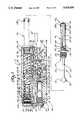
- FIG. 1is a semi-schematic, exploded side view, in partial cross-section, of an exemplary embodiment of a pressure actuated needleless hypodermic injection device provided in accordance with practice of this invention incorporating a first embodiment of a safety device for venting gas;
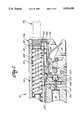
- FIG. 2is a semi-schematic, fragmentary, exploded side view of the pressure actuated needleless hypodermic injection device of FIG. 1, incorporating a second embodiment of a safety device for venting gas;
- FIG. 3is a semi-schematic front view of the needleless hypodermic injection device shown in FIG. 1 without the ampule assembly portion;
- FIG. 4is a semi-schematic, broken-away side view of FIG. 1 showing a safety device for locking the injection device actuating lever;
- FIG. 5is a semi-schematic, fragmentary, cross-sectional view taken on line 5--5 of FIG. 4;
- FIG. 6is a semi-schematic, fragmentary, enlarged view taken on line 6--6 of FIG. 5;
- FIG. 7is a semi-schematic, fragmentary, cross-sectional side view of the needleless hypodermic injection device of FIG. 1, having mounted thereon a gas-flow-regulator assembly provided in accordance with one embodiment of practice of this invention;
- FIG. 8is a semi-schematic, cross-sectional view of the flow-regulator device taken on line 8--8 of FIG. 7;
- FIG. 9is a semi-schematic, cross-sectional view of the flow-regulator device taken on line 9--9 of FIG. 7;
- FIG. 10is a semi-schematic, fragmentary, cross-sectional side view of the needleless hypodermic device of FIG. 1, having mounted thereon a second embodiment of a gas-flow-regulator assembly provided in accordance with this invention;
- FIG. 11is a semi-schematic, cross-sectional view of the gas-flow-regulator assembly taken on line 11--11 of FIG. 10;
- FIG. 12is a semi-schematic view of the gas-flow-regulator assembly taken in line 12--12 of FIG. 10 showing an adjustment knob;
- FIG. 13shows a method for filling an ampule from a vial of liquid medication by means of an adaptor assembly provided in accordance with practice of principles of this invention
- FIG. 13Ais an enlarged view of the adaptor assembly (without the ampule mounted therein) taken on line 13A of FIG. 13;
- FIG. 14shows activation of one embodiment of the device provided in accordance with this invention for ejecting liquid medication for hypodermic injection.
- This inventionrelates to a system for providing hypodermic injection.
- the system componentsinclude a pressure actuated needleless hypodermic injection device (which comprises an injector assembly, a medication ampule assembly, and a gas container) and an adaptor assembly for use on a medication vial for transferring medication from the vial to the medication ampule assembly of the injection device.
- a pressure actuated needleless hypodermic injection devicewhich comprises an injector assembly, a medication ampule assembly, and a gas container
- an adaptor assemblyfor use on a medication vial for transferring medication from the vial to the medication ampule assembly of the injection device.
- the injection device 10comprises a disposable compressed gas container or cylinder 12, an ampule assembly 14, and an injector assembly 16.
- the disposable gas container 12is configured to be mounted in the injector assembly 16 and the ampule assembly 14 is configured to be mounted externally on the injector assembly.
- the gas container 12 and ampule assembly 14operate in conjunction with the injector assembly 16 to eject liquid medication from the ampule assembly 14 for hypodermic injection.
- the ampule assemblyis preferably disposable, i.e., it is used only once and discarded. However, reusable ampule assemblies can be provided, if desired.
- injection device 10can be held in any position, the positions of the components of the device relative to each other are described below with the ampule assembly 14 considered to be mounted on the front end 17 of the injector assembly 16. The top and bottom of the device are described as shown in FIG. 1 of the drawings.
- the ampule assembly 14comprises an elongated tubular body portion 18 having an elongated cavity 20 centrally disposed along the length of the body 18 for holding liquid medication (not shown).
- the body 18can be made of a clear plastic by injection molding, other suitable materials, such as glass, can be used if desired.
- An orifice 22is in the first or front end 23 of the body 18 and is in communication with the elongated cavity 20 so that liquid medication can flow into and out from the cavity through the orifice.
- the back end 24 of the ampule body 18is provided with threads 25 which, as described below in detail, are used for mounting the ampule assembly on the injector assembly 16.
- the threads 25are preferably designed to provide a quick release of the ampule assembly from the injector assembly.
- the end 24 of the ampule bodycan be provided with a bayonet-type connection for engagement with an appropriately designed bayonet receptacle in the front end of the barrel.
- a plunger assembly 26,comprising a plunger rod 26a, having a piston 27 mounted on its forward end 28, is in the cavity 20 and is movable within the cavity for drawing liquid medication into the cavity through the orifice 22 and for forcing the liquid medication out from the cavity through the orifice.
- the pistonis preferably made of a flexible material such as rubber or plastic, or the like. Graduations 29 are provided on the body 18 so that the user can determine the exact amount of medication contained in the ampule.
- the piston 27has a groove 30 around its forward end so that a flange portion 31, having a flat front face 31a, is provided on its front end.
- the pistonpreferably has an outside diameter which is slightly larger than the inside diameter of the cavity 20 so that the piston is compressed when the plunger assembly 26 is in the cavity 20.
- the pistonforms an air- and fluid-tight seal between the plunger assembly and the walls of the cavity 20.
- the second end 32 of the plunger assemblyextends out from the cavity 20, and is preferably enlarged to provide a head 33 that can be gripped by a person using the ampule, and to which a force can be applied to move the plunger assembly 26 forward to eject medication through the orifice 22.
- the plunger head 33is ball-shaped.
- the plunger headcan be other than ball-shaped, if desired.
- the injector assembly 16is configured to receive and securely hold the ampule assembly 14 when the ampule assembly is filled with liquid medication, and to provide a force to move the plunger assembly 26 forward toward the orifice 22. Moving the plunger assembly 26 forward forces the liquid medication through the orifice 22 and into the skin of a person or animal receiving the hypodermic injection.
- the injector assembly 16comprises a body portion 34 which includes an elongated barrel 35, open at its forward or front end 36 and closed at its back end 38.
- the barrel front end 36is configured to receive and mount the ampule assembly 14.
- threads 39are provided in the front end 36 of the barrel 35 which mate with the threads 25 on the ampule body to provide a mounting for the ampule in the injector assembly 16.
- the threads 25 and mating threads 39are special "quick release" threads so that the ampule assembly can be mounted or removed with minimal turning.
- the ampule assemblycan be fully mounted or removed by turning it only one-half turn or 180°.
- the injector assembly body 34can be formed of metal or suitable plastics, as desired.
- a piston 40which is resiliently biased toward the back end 38 of the barrel 35 by a coil spring 42, is mounted in the barrel 35 for sliding movement along its length.
- the piston 40has a front-facing surface 44 which is preferably concave. If desired, the front-facing surface can be flat or can have other shapes.
- the piston surface 44is aligned with the head 33 of the plunger assembly 26 when the ampule 14 is mounted in the barrel 35.
- the piston 40has a second or rearwardly-facing surface 46 on which gas from the container 12 acts to push the piston forward.
- the piston 40has two raised rings 47 spaced apart from each other to form an annular cavity 48 around its end 40a.
- a Quad-ring 50or other form of a seal, such as an O-ring, or the like, is seated in the cavity 48.
- the sealing ringas a slightly larger diameter than the inner diameter of the barrel 35 to provide a gas-tight fit between the piston and the interior barrel walls.
- a removable plug 51which has threads 52 on its end for engagement with threads 53 in an openings 54 through the back end of the injector body 34 to form a gas-tight closure.
- the plug 51has a groove 57 around its circumference.
- a bore 58extends from the groove 57 through the plug opens out of the center of the plug base.
- the bore 58exits the plug through a cylindrical extension 51a at the center of the plug base.
- the extension 51aprovides a stop to limit the rearward motion of the piston in the barrel.
- the disposable container or cylinder 12 containing compressed air, such as CO 2is in a chamber 55 formed in a rear portion of the injector body 34 parallel to and below the barrel 35. Having a design where the chamber 55 is parallel to and below the barrel 35 minimizes the length of the device and makes it more compact.
- the container 12 in the illustrated embodimenthas the shape of a standard CO 2 cylinder with a frangible cap or seal 56 on its front-facing end, containers having other shapes can be used, if desired.
- the container 12can be made of metal or plastic.
- the frangible seal 56 on the cylinderis designed to be punctured to allow gas to escape from the cylinder as the device 10 is actuated to provide the force for the hypodermic injection.
- gas cylinderscan be placed into and removed from the chamber 55 through an opening 59 that extends through the back end of the injector body 34 below the opening 54 in which the plug 51 is mounted.
- the opening 59has special quick release threads 63, similar to the threads 25 and 39 on the ampule assembly 14 and front barrel end 36, respectively, which engage quick release threads 60 on a plug 61 when the plug is in place in the opening 59.
- the plug 61can be removed to open the chamber 55 so that an expended gas cylinder can be quickly removed and a new cylinder installed.
- the plug 61When the plug 61 is in place in the opening 59, it urges the gas cylinder 12 forward against a resilient gasket 62, having an opening 64 through its center and mounted in the front end of the chamber between the gas cylinder seal 56 and the front chamber wall 65.
- a resilient gasket 62having an opening 64 through its center and mounted in the front end of the chamber between the gas cylinder seal 56 and the front chamber wall 65.
- a first passageway 66is provided in the injector body 34 through which gas flows to the back end 38 of the barrel 35 from the gas cylinder 12. Gas flows from the cylinder 12, through the gasket opening 64, and through an outlet 68 lined up with the opening 64 and extending from the chamber 55 into the passageway 66.
- the passageway 66extends vertically from the chamber outlet 68 to a "T" connection 69.
- the passageway 66extends horizontally toward the back end of the injector body 34 from the "T" connection and then upwardly, opening into the groove 57 in the plug 51.
- the groove 57opens into the bore 58, which opens into a cavity 70 between the forward-facing surface 71 of the plug 51 and the rearward-facing surface 46 of the piston 40.
- a second passageway 72extends forward from the "T" connection 69 within the body 34.
- the passageway 72is configured to be open for venting gas released from the gas cylinder 12 to the atmosphere through the front end 36 of barrel 35 when the end 24 of the ampule assembly 14 is not fully mounted or inserted in the barrel.
- Meansare provided for sealing the second passageway 72 to prevent venting gas through the passageway 72 to the atmosphere.
- the sealis provided only when the ampule assembly 14 is fully mounted on the injector assembly barrel, i.e., when the threaded end 24 of the ampule assembly is screwed tightly into the threaded front end 36 of the barrel 35.
- gas pressure in the injector assemblydoes not increase to a sufficient level to move the piston 40 forward against the spring 42.
- the injector assemblycannot be used as a power source for a pencil or other potential projectile which may be inserted into the barrel 35 when the ampule assembly is not installed. This is an important safety interlock feature which ensures that foreign objects cannot be shot from the injector assembly.
- means for sealing the passageway 72comprises a valve stem 74 mounted for sliding movement along the length of the passageway 72.
- the valve stem 74rides in the passageway 72 on two rings 75 spaced apart on the valve stem along its length. More than two rings 75 can be used, if desired.
- the valve stem 74is an L-shaped rod, with the first or forward end 76 of the valve stem having a 90° bend in it so that a portion 78 of the valve stem extends upwardly into the opening 80 in the forward barrel end 36.
- a valve seat 82is at the back or upstream end of the passageway 72 adjacent the "T" connection 69.
- a resilient ball 84is located between the valve seat 82 and the second or rearward-facing end 86 of the valve stem.
- a plugcan be used in place of the ball 84.
- the upwardly-extending portion 78 of the valve stem 74is configured to engage the threaded end 24 of the ampule assembly 14 as it is being screwed into the forward end 36 of the barrel 35. As the end 24 of the ampule assembly is screwed into the barrel 35, it engages the portion 78 of the valve stem 74 and thereby pushes the valve stem rearwardly toward the valve seat 82.
- the ball 84rides over a slot 87 along the bottom of the passageway 72 as it is pushed rearwardly by the valve stem 74.
- ampule assembly 14When the ampule assembly 14 is fully mounted, i.e., when it has been screwed tightly into the barrel 35, it holds the valve stem 74 in place at its rearmost position in the passageway 72 to thereby hold or trap the ball 84 in gas-tight sealing engagement on the valve seat.
- gas released from the cylinder 12cannot vent through the passageway 72 but, instead, is directed through the first passageway 66 into the chamber or cavity 70 to act on the rearward-facing surface 46 of the piston 40.
- FIG. 2a semi-schematic, fragmentary side view, in partial cross-section, of the hypodermic injection device 10 of FIG. 1 is shown, incorporating a second embodiment of a safety device for venting gas to the atmosphere when the ampule assembly 14 is not mounted in the barrel 35.
- an opening 92extends from the "T" connection 69 through the injector body 34 to the atmosphere.
- the opening 92is configured to be open when the end 24 of the ampule assembly 14 is not fully mounted or inserted in the forward end 36 of the barrel 35.
- Meansare provided for sealing the opening 92 to prevent venting gas to the atmosphere when the ampule assembly 14 is fully mounted.
- the gas-sealing meansinclude a valve seat 94 on the outlet end of the injector body opening 92, a slide 96 mounted in the injector body 34 for movement in a horizontally-extending elongated cavity 97 in the front end of the injector body toward and away from the valve seat, and a resilient ball 98 located between the valve seat 94 and the back or rearward-facing end 100 of the slide 96. If desired, a plug can be used in place of the ball 98.
- a pin 102extends vertically from the front end 104 of the slide 96 into the opening 80 in the barrel forward end 36.
- the threaded end 24 of the assembly 14engages the pin 102 and thereby pushes the slide 96 rearwardly along the length of the injector body 34 toward the valve seat 94.
- the ball 98rides over a slot 99 along the bottom of the cavity 97 as it is pushed rearwardly by the slide 96.
- the injector assembly 16includes an actuator assembly 106 mounted on the injector body 34 for releasing gas from the gas cylinder 12.
- the actuator assembly 106is in a slot 107 formed by side walls 108 and 109 of the body 34 located below the barrel 35 and forward of the gas cylinder chamber 55.
- the actuator assemblyincludes an actuating lever 110, having a circular opening 111 through its bottom rear portion configured to receive a pin 112 that extends between the side walls 108 and 109 perpendicular to the length of the injector body.
- the pin 112is through the opening 111 so that the actuating lever 110 can be pivoted on the pin.
- An elongated lance 114is provided with its forward end 116 mounted in a cylindrical pin 117 which is mounted for rotational movement in a second opening 118 through the actuating lever above and slightly forward of the opening 111.
- the lancewhich has a point 120 on its rearward-facing end, extends from the actuating lever 110 through an opening 122 in the injector assembly body 34.
- a cylindrical plug 123is mounted on the lance 114 and moves within a cylindrical cavity 125 which extends from the opening 122 in the injector body 34.
- An elongated groove 114ais in a portion of the top surface of the lance 114 along its length.
- the grooveprovides a pathway for venting gas through a vent slot 127, which extends through the front facing surface 34a of the body 34 in the slot 107, into the top of the cavity 125, to the atmosphere.
- the lance point 120is spaced apart from and adjacent the gas cylinder seal 56 when the actuating lever is in its unactuated position, as shown in FIG. 1, and the rearmost portion of the groove 114a is in the cavity 125.
- the actuating lever 110can be moved from its unactuated to its actuated position by squeezing it so that the front end 110a of the lever 110 moves upwardly toward the slot 107, while the back end pivots on the pin 112.
- the lanceis moved rearwardly through the opening 122, and the point 120 is forced through the frangible gas cylinder seal 56, puncturing the seal and releasing the gas from the cylinder.
- the plug 123moves further into the cavity 125.
- the clearance between the lance 114 and the opening 122is such that gas is prohibited from escaping in sufficient quantities to affect the operation of the injection device.
- the groove 114aextends into the passageway 66. Gas from behind the piston 40 (including gas in the passageway 66 and any gas remaining in the container 12) is then vented through the groove 114a, into the cavity 125, and out to the atmosphere through the vent 127. After the gas is vented to the atmosphere, the spring 42 returns the piston to its unactuated position at the back end 38 of the barrel.
- the actuating leveris biased to its unactuated position by means of a leaf spring 124 mounted in the front portion 110a of the lever 110.
- the spring 124extends upwardly from the lever 110 so that its curved upper end 126 contacts a surface 128 of the body 34 that extends horizontally below and defines the bottom wall of the passageway 72 and the top of the slot 107.
- a safety interlock 129which prohibits movement of the actuating lever 110 from its unactuated to its actuated position when the interlock is in the "locked" position.
- the interlockis provided by means of a keyhole-shaped slot 130 (best seen in FIGS. 1, 5 and 6) cut through the lever 110 in a portion of the lever forward of the openings 111 and 118.
- the slothas a narrow bottom portion 132 and a circular top portion 134.
- a lock rod 136having flats 137 on opposite sides, is mounted on the injector body between the walls 108 and 109.
- the lock rod 136can be rotated about an axis transverse to the length of the injector body by means of levers 138 and 139, each of which is in one end of the lock rod.
- the lock rod 136extends through the circular top or enlarged portion 134 of the slot 130 when the actuating lever 110 is in its unactuated position (as shown in FIG. 1).
- the flats 137extend across the slot as shown in FIG. 1, and the lever is prohibited from being moved upwardly, i.e., the lever is prohibited from being squeezed to its actuated position. Actuation of the lever is prohibited because the rod has a diameter greater than the width of the bottom portion 132 of the slot 130.
- a first exemplary embodiment of a force-varying meansprovided in accordance with this invention comprises a gas-flow-regulator assembly 140 mounted at the back end 38 of the barrel 35 in place of the plug 51 described with reference to FIGS. 1 and 2.
- the flow-regulator assembly 140comprises a body portion 142 that has a threaded end 144 for engaging the threads 53 in the opening 54 through the back end of the injector body 34.
- a groove 145is around the circumference of the base of the threaded end 144 of the body 142.
- a disk 146in the form of an open cylinder or cup having a flat center portion 148 with a circular wall 150 around its periphery and extending rearwardly, is mounted in the body 142.
- the disk 146has an opening 152 through its center which is mounted on a hollow circular extension portion 154 of the body 142.
- the extension 154acts like an axle on which the disk can be rotated.
- a circular plenum piece 156fits into the rearward-facing cylindrical cavity 158 formed by disk wall 150.
- the plenum piece 156has a rearward-facing central cavity 160 which, in the illustrated embodiment, is circular, and an hexagonal opening 161 is through the center of the cavity 160.
- the opening 161is mounted onto a further hollow extension 162 that is hexagonal in shape, is smaller in diameter, and extends from the hollow extension 154.
- a cap 168having threads 169 around its outer circumference, with an interior center portion 170 configured to engage the circular top portion 166 of the plug 163, is threaded into engagement with threads 171 on the rearward-facing end of the flow regulator body 142.
- the cap 168when screwed in place, holds the flow-regulator assembly together.
- each orifice setincludes five orifices, beginning with the largest in diameter designated 172a and decreasing in size in a counterclockwise direction, as shown in FIG. 5, to the smallest in diameter designated 172e.
- the orifice 172ais 0.080 inch in diameter
- the orifice 172bis 0.060 inch
- the orifice 172cis 0.040 inch
- the orifice 172dis 0.020 inch
- the orifice 172eis 0.010 inch.
- Other sized gas-flow-restricting orificescan be provided, if desired.
- Each orifice setis identical to the other set, and each orifice 172 is spaced apart 120° from each other orifice of the same size.
- the plenum piece 156includes three outlets 174, 176 and 178 through it, spaced apart 120° from each other, each of which is in communication with a bore 180 through the center of the body 142.
- the bore 180opens into the groove 145 which, in turn, is open to the gas flow passageway 66.
- Each of the plenum outlets 174, 176 and 178directs gas released from the gas cylinder through one of the orifices 172 in each set of orifices and through one of three gas ports 182 spaced apart 120° from each other through the flow regulator body 142.
- gas released from the cylinder 12passes through the passageway 66, into the groove 145 in the body 142, through the bore 180, and into the plenum piece 156. From the plenum piece 156, the gas passes through the outlets 174, 176 and 178, through three orifices 172, through the three associated gas ports 182, and into the cavity 70 to act on the rearward-facing surface 46 of the piston 40.
- a handle 184is mounted in the circular disk wall 150 and extends upwardly out through a slot 186 in the top portion of the regulator body 142.
- the handle 184provides a means to rotate the disk 146 to a selected position for placing one orifice 172 in each of the three sets of orifices in alignment with one of the plenum outlets 174, 176 and 178.
- the diskcan be rotated through one of five positions where, in each such position, one of the gas-flow-restricting orifices of equal size in each set is in alignment with a different one of the plenum outlets.
- Numberscan be positioned on the rear-facing surface 142a of the body 142 to line up with the handle 184 when the handle is in position corresponding to the particular size orifice aligned with the outlets 174, 176 and 178.
- numbers 1-5are on the surface 142a to provide five pressure settings.
- Disks having more or fewer than three sets of orifices and having more or fewer than five orifices per setcan be provided, if desired. There can be more or fewer than three outlets provided in the plenum pieces.
- the number of gas ports 182corresponds to the number of plenum outlets which, in turn, corresponds to the number of sets of disk orifices 172.
- FIGS. 10-13A second preferred embodiment of a gas-flow-regulator assembly 186 for varying the force of gas acting on the piston 40 is shown in FIGS. 10-13.
- the flow-regulator assembly 186having a body portion 187, is mounted at the back end 38 of the barrel 35 in place of the plug 51 described with reference to FIGS. 1 and 2.
- the assembly body 187has a threaded end 188 for engaging the threads 53 in the opening 54 through the back end of the injector body 34.
- a groove 189which is around the circumference of the base of the threaded end 188 of the body 187, is open to the passageway 66 in the injector body 34.
- the assembly 186includes a valve seat 190 at the outlet end of a bore 191, which opens into the groove 189.
- a resilient ball 194is downstream from the seat 190 for contacting the seat.
- a coil spring 196is provided for adjustably biasing the ball onto the seat. If desired, a plug, or the like, can be used in place of the ball 194.
- the spring 196is in an outlet chamber 197 between the ball 184 and the stem 198 of an adjustable knob 199, which is threaded into a horizontal opening 200 through the center of the end of the body 187 of the flow-regulator assembly 186.
- Three gas ports 202, 204 and 206respectively, spaced apart 120° from each other, extend out from the chamber 197 through bores 208.
- gas from the cylinder 12passes through the passageway 66, into the groove 189, and through the bore 191. From the bore 191, the gas travels between the ball 194 and the seat 190, through the bores 208, and then through the three gas ports 202, 204 and 206 and into the cavity 70 to contact the rearwardly-facing surface 46 of the piston 40.
- the knob 199has a slot 212 through it extending around approximately the bottom one-third of its perimeter.
- An indicator pin 214extends in a rearward direction out from the regulator assembly body 187 into the slot 212.
- the knob 199has a series of numerals, or settings, from 1 to 5 on it, indicating the force being exerted. If desired, a cap 215 can be provided to cover the knob 199.
- FIG. 13shows one embodiment of a method for filling the ampule assembly 14 with liquid medication.
- the ampule assembly 14is mounted onto a preferred embodiment of an adaptor assembly 220 provided in accordance with this invention, which, in turn, is snap mounted onto vial(s) 222 of liquid medication.
- the adaptor assembly 220 of this inventionincludes an assembly body 224 made, for example, of a clear plastic. Other suitable materials can be used, if desired.
- the body 224includes two cavities 226 and 228, respectively, spaced apart from each other on opposite ends of the body.
- the first cavity 226is configured to receive the cap 230 on the vial 222 of liquid medication.
- the second cavity 228has threads 230 for engaging threads 232 on the discharge or orifice end 23 of the ampule assembly 14.
- the threads 230 and 232are quick release threads, similar to the threads 25 and 39 on the end 24 of the ampule assembly and in the front end of the barrel, so that the ampule assembly can be mounted and removed from the cavity 228 by turning the assembly approximately one-half turn.
- Adaptor assemblies having first cavities of various sizescan be provided to accommodate the various sized caps of standard medication vials.
- the diaphragm 234has a cylindrical recess 235 formed in a portion of its center adjacent the cavity 228.
- the diaphragmhas an elongated slit 236 extending through its center, registered with the cylindrical recess 235. It is contemplated that such a slit 236 will have a length of from about 0.030 inch to about 0.050 inch. Slits having other lengths can also be provided, if desired.
- the slit 236is closed when the ampule assembly is not in the cavity and the diaphragm is in its non-flexed or original state (as is shown in FIG. 13A).
- the end 23 of the assemblyrealigns the center portion of the diaphragm 234 to thereby open the slit 236 into the recess 235.
- the diaphragmreturns to its original state and the slit 236 returns to its original closed position.
- the diaphragm 234provides an air-restricting seal between the end 23 of the ampule assembly 14 and the adaptor assembly 220 when the ampule assembly is mounted therein. If desired, a hole can be used instead of a slit.
- a hollow, tubular needle 237is mounted in the adaptor assembly body 224.
- the needleis through the center of the portion 238 of the body 224 that separates the first and second cavities 226 and 228 from each other.
- the top opening of the needleis positioned in the cylindrical diaphragm recess 235 with its point extending a sufficient distance into the first adaptor body cavity 226 to pierce the cap 230 of the vial 222 when the adaptor assembly is on the vial.
- a cap 239can be provided for insertion into the cavity 228 to maintain sterility when the ampule is not in the cavity 228 for filling.
- the cap 239is attached to the adaptor body 224 by means of a "living" hinge 241.
- a vial 222 filled with liquid medicationis snapped into the cavity 226 of the adaptor assembly 220 so that the needle 237 is through the cap 230 on the vial.
- a disposable ampule assemblyis then taken from its sterile container and the cap 239 is then removed from the adaptor cavity 228.
- the ampule assembly 14, with the plunger assembly 26 partially inserted into the ampule cavity 20,is then screwed into the adaptor body cavity 228, so that the ampule threads 232 engage the threads 230 in the cavity 228.
- mounting of the ampule assembly in the cavity 228forces open the slit 236 in the diaphragm 234.
- the adaptor assembly 224 and the vial 222are then inverted so that liquid medication in the vial covers the point of the needle 237.
- Airis then pumped into the vial 222 by pushing the plunger assembly 26 forward in the direction of the arrow marked "A” in FIG. 13.
- Medicationis then drawn in through the needle 237, into the cylindrical diaphragm recess 235, through the open diaphragm slit 236, through the ampule assembly orifice 22, and into the ampule cavity 20 by pulling on the end 33 of the plunger assembly 26 to move the plunger assembly in the direction of the arrow marked "B" in FIG. 13.
- the ampule assembly 14is unscrewed from the filling assembly cavity 228, and the cap 239 reinstalled.
- the ampule assembly 14is filled with slightly more medication than is desired so that any air in the ampule can be ejected by pushing the plunger 26 back into the cavity 20 an appropriate distance, while the ampule assembly is held in the vertical position, with the orifice 22 up.
- the design and configuration of the adaptor assembly diaphragmis an important feature of the system provided in accordance with practice of principles of this invention.
- a liquid-tight sealis provided between the end 23 and the diaphragm 234.
- the diaphragmreturns to its original condition, as shown in FIG. 13A, thereby closing the slit 236 and preventing liquid medication from passing from the vial into the cavity 228.
- the cavity 228remains dry and free of medication. This ensures that residual medication, which could become contaminated, will not be in the adaptor cavity 228 between fillings.
- the cavity 20 of the ampule assembly 14have substantially the same circular cross-section as standard syringes so that a given longitudinal movement of the plunger assembly 26 in the present invention will draw substantially the same volume of liquid medication into the cavity 20 as would be drawn into a conventional syringe by the same amount of movement.
- an insulin-dependent diabetic or other long-term medication user, or health care professionalwho has become accustomed to filling a standard syringe for injecting medication, will be able to use the same learned movement to fill the ampule of the present invention.
- FIG. 14after the above-described filling operation of the cavity 20 of the ampule assembly 14 has been completed, the end 24 of the ampule assembly 14 is screwed into the threaded forward end 36 of the barrel 35 of the injector assembly 16.
- the special quick release ampule assembly threads 25engage the portion 78 of the valve stem 74 and push the valve stem rearwardly toward the valve seat 82.
- valve stem 74holds the valve stem 74 in place at its rearmost position in the passageway 72 to thereby hold or trap the ball 84 in sealing engagement on the valve seat 82.
- gascannot vent to the atmosphere through the passageway 72.
- disposable ampule assembliescan be provided pre-filled with the appropriate medication. In this embodiment, no filling operation is necessary, and the ampule assembly can be removed from its sterile package and mounted directly onto the injector assembly.
- the chamber 55Prior to externally mounting the ampule assembly 14 onto the injector assembly 16, and with the safety 129 in the locked position, the chamber 55 is opened by removing the plug 61, and a fresh CO 2 container 12 is installed. The plug is then replaced to thereby hold the container 12 securely in the chamber.
- the end 23 of the ampule assembly 14is placed against the properly prepared skin 240 of the user.
- the safety lock rod 136is rotated by means of the levers 138 and 139 from its locked position with the flats 137 across the slot 130, as shown in FIG. 1, to its unlocked position with the flats 137 lined up with the slot, as shown in FIG. 14.
- the narrow portion 132 of the slot 130can be moved by the rod.
- the actuating lever 110is squeezed to move it upwardly into the slot 107 in the assembly body 34 toward the barrel 35.
- the lance 114is moved rearwardly through the opening 122 toward the container 12, and the plug 123 moves further into the cavity 125.
- the lance point 120is forced through the frangible container seal 56, puncturing the seal and releasing the compressed gas from the container.
- the released gastravels through the outlet 68 and is conducted via the passageway 66, into the groove 57 in the plug 51, through the bore 58 and into the cavity 70, to act on the rearward-facing surface 46 of the piston 40.
- the force of the gasdrives the piston 40 forward against the spring 42 toward the forward end 36 of the barrel 35.
- the pistonstrikes the head 33 of the plunger 26, engaging the plunger and forcing it forward against the liquid medication contained in the cavity 20 of the ampule 14.
- the face of the pistonis concave so that when the piston engages the plunger head 33, the concave face aligns the plunger in the center of the barrel 35 and maintains the proper plunger alignment as the plunger moves forward.
- liquid medicationis ejected through the orifice 22 of the ampule 14 and into the skin 240.
- the use of the injection device 10 of the present inventionleaves no puncture wound and causes little pain to the user.
- the force of the gas acting on the rearward-facing surface 46 of the piston 40is directly proportional both to the pressure of the gas and to the area of the surface 46.
- a piston (and associated barrel) with a relatively larger cross-sectional areais used, the force on the rearward-facing surface 46 exerted by the gas at a given pressure will be relatively larger.
- a piston (and associated barrel) with a relatively smaller cross-sectional areais used, the force on the rearward-facing surface will be relatively smaller.
- the piston and barrelcan be considered to act in combination as an accumulator for magnifying the force provided by the compressed gas.
- the actuating lever 110is released.
- the actuating leverreturns to its unactuated position (as shown in FIG. 1) by the action of the spring 124.
- the lock rod 136 of the safety 129is rotated to its locked position by moving the levers 138 and 139 so that the flats 137 are across the slot 130, as shown in FIG. 1.
- the injection device 10can be prepared to be actuated again by removing the plug 61, replacing the spent gas container 12 in the chamber 55 with a fresh container, and reinstalling the plug 61. After this operation is complete, a fresh ampule assembly can be removed from its sterile container and filled with liquid medication for use as described above.
- FIGS. 7-10in addition to FIG. 14 the operation of the injection device lo, when the gas-flow-regulator assembly 140 is mounted in the back end 38 of the barrel 35 in place of the plug 51, is described.
- the preparation of the device 10 for the hypodermic injectionis the same as the preparation described above with reference to FIG. 14.
- a determinationis made by the user regarding the desired velocity of medication ejected through the orifice 22. This evaluation can be done by correlating the medication viscosity with desired orifice size and desired injection velocity and selecting the appropriately sized disk orifice. For example, when a disk such as the one described with reference to FIGS.
- the end 23 of the ampule assemblyis placed against the properly prepared skin 240 (as shown in FIG. 14), the safety 129 is unlocked, and the lever 110 is actuated by squeezing, thereby releasing the gas from the compressed gas container 12.
- the gaspasses from the container through the opening 68 and into the passageway 66. From the passageway 66, it passes into the circumferential groove 145 and through the assembly body bore 180. From the bore 180, the gas passes through the plenum outlets 174, 176 and 178, through the three selected disk orifices 172 lined up with the associated plenum outlets, and through the three gas ports 182 into the cavity 70 behind the piston 40.
- the gas entering the cavity 70acts on the rearward-facing surface 46 of the piston 40 to drive it forward to thereby eject the medication through the orifice 22 of the ampule assembly 14.
- the gas flow to the piston 40is more or less restricted, thereby enabling the user to select the minimum injection velocity (as provided by the particular orifice sizes in the disk) sufficient for injecting the liquid medication through the skin at the injection location.
- the minimum injection velocityas provided by the particular orifice sizes in the disk
- gas flowis relatively more restricted, thereby reducing the pressure of gas acting on the piston and reducing the force on the piston.
- the restricted gas flowcauses the piston 40 to move more slowly toward the front end 36 of the barrel 35, thus providing liquid medication having relatively less injection velocity.
- FIGS. 10-12in addition to FIG. 14), the operation of the injection device 10, when the gas-flow-regulator assembly 186 is mounted in the back end 38 of the barrel 35, is described.
- the preparation of the device 10 for hypodermic injectionis the same as the preparation described above with reference to FIG. 14.
- a determinationis made by the user regarding the desired velocity of medication to be ejected through the orifice 22. This evaluation is the same as the evaluation made when the device 10 has the flow-regulator assembly 140 mounted thereon as is described above.
- the knob 199 on the assembly 186can be turned for providing more or less tension on the regulator assembly spring 196
- maximum forceis on the assembly spring, thereby minimizing the amount of gas that will pass between the ball 194 and the seat 190 during a given time period, to thereby relatively decrease the pressure of gas behind the piston 40.
- Decreasing the pressure of gas behind the pistondecreases the force of the gas acting on the rearward-facing surface 46 of the piston, thereby decreasing piston velocity. This, in turn, decreases the velocity of the medication as it is being ejected through the orifice 22 in the ampule assembly.
- the end 23 of the ampule assemblyis placed against the properly prepared skin 240, the safety 129 is unlocked, and the lever 110 is actuated, releasing the gas from the compressed gas container 12.
- the gaspasses from the container, through the opening 68, and into the passageway 66. From the passageway 66, it passes into the circumferential groove 189, into the assembly body bore 191, past the seat 190 and ball 194, into the cavity 197.
- the gasexits the cavity 197 through the bores 208, through the gas ports 202, 204 and 206, and into the cavity 70 behind the piston 40.
- the gas entering the cavity 70acts on the rearward-facing surface 46 of the piston 40 to drive it forward to thereby eject the medication through the orifice 22 of the ampule assembly 14.
- the setting on the knob 199controls the velocity of the medication being ejected through the orifice 22.
- the embodiments of the injection device 10, having either the flow-regulator assembly 140 or the flow-regulator assembly 186,provide an easy and efficient means to select the minimum required velocity to appropriately penetrate the skin of the user for a given injection site and liquid medication viscosity. Furthermore, providing an injection device of simple construction enables the device to be manufactured economically and enhances reliability.
- hypodermic injection system of this inventionwhich comprises the needleless hypodermic device 10, which includes an injector assembly 16 having an injector body 34 with a chamber 55 for a compressed gas container 12 and an ampule assembly 14 mounted on the injector body, and the adaptor assembly 220, are for illustrative purposes. Because of variations which will be apparent to those skilled in the art, the present invention is not intended to be limited to the particular embodiments described above. The scope of the invention is defined in the following claims.
Landscapes
- Health & Medical Sciences (AREA)
- Vascular Medicine (AREA)
- Engineering & Computer Science (AREA)
- Anesthesiology (AREA)
- Biomedical Technology (AREA)
- Heart & Thoracic Surgery (AREA)
- Hematology (AREA)
- Life Sciences & Earth Sciences (AREA)
- Animal Behavior & Ethology (AREA)
- General Health & Medical Sciences (AREA)
- Public Health (AREA)
- Veterinary Medicine (AREA)
- Infusion, Injection, And Reservoir Apparatuses (AREA)
Abstract
Description
Claims (38)
Priority Applications (5)
| Application Number | Priority Date | Filing Date | Title |
|---|---|---|---|
| US07/238,360US5024656A (en) | 1988-08-30 | 1988-08-30 | Gas-pressure-regulated needleless injection system |
| JP1509696AJPH04500166A (en) | 1988-08-30 | 1989-08-23 | Needleless injection system controlled by gas pressure |
| PCT/US1989/003629WO1990001961A1 (en) | 1988-08-30 | 1989-08-23 | Gas-pressure-regulated needleless injection system |
| AU42177/89AAU4217789A (en) | 1988-08-30 | 1989-08-23 | Gas-pressure-regulated needleless injection system |
| DE19893990984DE3990984T1 (en) | 1988-08-30 | 1989-08-23 | GAS PRESSURE CONTROLLED NEEDLE-FREE INJECTION SYSTEM |
Applications Claiming Priority (1)
| Application Number | Priority Date | Filing Date | Title |
|---|---|---|---|
| US07/238,360US5024656A (en) | 1988-08-30 | 1988-08-30 | Gas-pressure-regulated needleless injection system |
Publications (1)
| Publication Number | Publication Date |
|---|---|
| US5024656Atrue US5024656A (en) | 1991-06-18 |
Family
ID=22897530
Family Applications (1)
| Application Number | Title | Priority Date | Filing Date |
|---|---|---|---|
| US07/238,360Expired - Fee RelatedUS5024656A (en) | 1988-08-30 | 1988-08-30 | Gas-pressure-regulated needleless injection system |
Country Status (4)
| Country | Link |
|---|---|
| US (1) | US5024656A (en) |
| JP (1) | JPH04500166A (en) |
| AU (1) | AU4217789A (en) |
| WO (1) | WO1990001961A1 (en) |
Cited By (149)
| Publication number | Priority date | Publication date | Assignee | Title |
|---|---|---|---|---|
| US5312333A (en)* | 1992-04-03 | 1994-05-17 | United States Surgical Corporation | Endoscopic material delivery device |
| USD349958S (en) | 1992-07-24 | 1994-08-23 | Bioject Inc. | Needleless injector |
| US5383851A (en)* | 1992-07-24 | 1995-01-24 | Bioject Inc. | Needleless hypodermic injection device |
| US5501666A (en)* | 1995-05-24 | 1996-03-26 | Mycone Dental Supply Co. | Needleless injector |
| US5503628A (en)* | 1995-03-15 | 1996-04-02 | Jettek, Inc. | Patient-fillable hypodermic jet injector |
| US5536249A (en)* | 1994-03-09 | 1996-07-16 | Visionary Medical Products, Inc. | Pen-type injector with a microprocessor and blood characteristic monitor |
| US5540657A (en)* | 1994-07-15 | 1996-07-30 | Collagen Corporation | Delivery device for injectable materials |
| US5569189A (en)* | 1992-09-28 | 1996-10-29 | Equidyne Systems, Inc. | hypodermic jet injector |
| USD375789S (en) | 1994-08-12 | 1996-11-19 | Survival Technology, Inc. | Variable dose, reloadable auto-injector |
| EP0754068A1 (en) | 1994-04-06 | 1997-01-22 | Alain Moreau Defarges | Needleless jet injection device |
| US5697917A (en) | 1996-02-29 | 1997-12-16 | Medi-Ject Corporation | Nozzle assembly with adjustable plunger travel gap |
| US5722953A (en) | 1996-02-29 | 1998-03-03 | Medi-Ject Corporation | Nozzle assembly for injection device |
| US5730723A (en)* | 1995-10-10 | 1998-03-24 | Visionary Medical Products Corporation, Inc. | Gas pressured needle-less injection device and method |
| US5769138A (en)* | 1996-04-01 | 1998-06-23 | Medi-Ject Corporation | Nozzle and adapter for loading medicament into an injector |
| US5779678A (en)* | 1995-12-02 | 1998-07-14 | Smiths Industries Plc | Fluid administration apparatus |
| US5800388A (en) | 1996-02-29 | 1998-09-01 | Medi-Ject Corporation | Plunger/ram assembly adapted for a fluid injector |
| US5820602A (en)* | 1995-09-08 | 1998-10-13 | Visionary Medical Products, Inc. | Pen-type injector drive mechanism |
| US5840061A (en)* | 1995-05-15 | 1998-11-24 | Ferton Holding | Ejection apparatus for the high pressure ejection of a liquid |
| US5846233A (en) | 1995-01-09 | 1998-12-08 | Medi-Ject Corporation | Coupling device for medical injection system |
| US5865795A (en) | 1996-02-29 | 1999-02-02 | Medi-Ject Corporation | Safety mechanism for injection devices |
| US5875976A (en) | 1996-12-24 | 1999-03-02 | Medi-Ject Corporation | Locking mechanism for nozzle assembly |
| US5911703A (en)* | 1997-05-22 | 1999-06-15 | Avant Drug Delivery Systems, Inc. | Two-stage fluid medicament jet injector |
| US5921967A (en) | 1996-02-29 | 1999-07-13 | Medi-Ject Corporation | Plunger for nozzle assembly |
| US5981505A (en)* | 1993-01-26 | 1999-11-09 | The Trustees Of The University Of Pennsylvania | Compositions and methods for delivery of genetic material |
| US5993412A (en)* | 1997-05-19 | 1999-11-30 | Bioject, Inc. | Injection apparatus |
| WO2000016828A1 (en)* | 1998-09-23 | 2000-03-30 | Loomis Dale J | Biolistic apparatus for delivering substances into cells and tissues |
| WO2000033899A1 (en)* | 1998-12-08 | 2000-06-15 | Bioject, Inc. | Needleless syringe with prefilled cartridge |
| WO2000035520A1 (en)* | 1998-12-18 | 2000-06-22 | Biovalve Technologies, Inc. | Injection devices |
| US6080130A (en)* | 1998-11-14 | 2000-06-27 | Castellano; Thomas P. | Gas power source for a needle-less injector |
| US6123684A (en)* | 1998-07-27 | 2000-09-26 | Medi-Ject Corporation | Loading mechanism for medical injector assembly |
| US6186982B1 (en) | 1998-05-05 | 2001-02-13 | Elan Corporation, Plc | Subcutaneous drug delivery device with improved filling system |
| US6210359B1 (en) | 2000-01-21 | 2001-04-03 | Jet Medica, L.L.C. | Needleless syringe |
| US6223786B1 (en) | 1998-11-14 | 2001-05-01 | Pen Jet Corporation | Apparatus and method for mixing medication and filling an ampule of a needle-less injector |
| US6258062B1 (en) | 1999-02-25 | 2001-07-10 | Joseph M. Thielen | Enclosed container power supply for a needleless injector |
| US20010039394A1 (en)* | 1993-07-31 | 2001-11-08 | Duncan A. Greenhalgh | Needle-less injector |
| US20020004639A1 (en)* | 2000-01-07 | 2002-01-10 | Willis John P. | Injection device |
| US6383168B1 (en) | 1998-12-08 | 2002-05-07 | Bioject Medical Technologies Inc. | Needleless syringe with prefilled cartridge |
| US6406455B1 (en) | 1998-12-18 | 2002-06-18 | Biovalve Technologies, Inc. | Injection devices |
| WO2002055139A1 (en)* | 2001-01-11 | 2002-07-18 | Powderject Research Limited | Needleless syringe |
| US20020151842A1 (en)* | 2000-11-30 | 2002-10-17 | Gonnelli Robert R. | Injection systems |
| US6471669B2 (en) | 2001-03-05 | 2002-10-29 | Bioject Medical Technologies Inc. | Disposable needle-free injection apparatus and method |
| US6474369B2 (en) | 1995-05-26 | 2002-11-05 | Penjet Corporation | Apparatus and method for delivering a lyophilized active with a needle-less injector |
| US6500239B2 (en) | 2001-03-14 | 2002-12-31 | Penjet Corporation | System and method for removing dissolved gas from a solution |
| US6500150B1 (en) | 1997-06-16 | 2002-12-31 | Elan Pharma International Limited | Pre-filled drug-delivery device and method of manufacture and assembly of same |
| US20030083612A1 (en)* | 2001-04-13 | 2003-05-01 | Penjet Corporation | Apparatus for needle-less injection with a degassed fluid |
| US6558348B2 (en) | 2000-04-07 | 2003-05-06 | Equidyne Systems, Inc. | Low cost disposable needleless injector system for variable and fixed dose applications |
| US20030088214A1 (en)* | 1999-10-11 | 2003-05-08 | Felton International, Inc. | Universal protector cap with auto-disable features for needle-free injectors |
| US20030088207A1 (en)* | 1999-11-23 | 2003-05-08 | Felton International, Inc. | Jet injector with hand piece |
| US20030100862A1 (en)* | 2001-07-19 | 2003-05-29 | Edwards Evan T. | Medical injector |
| US6607510B2 (en) | 2001-11-09 | 2003-08-19 | Bioject Medical Technologies Inc. | Disposable needle-free injection apparatus and method |
| US6610042B2 (en)* | 1997-12-05 | 2003-08-26 | Felton Medical, Inc. | Disposable unit-dose jet-injection syringe for pre-filled and/or transfilled liquid injectable medical drug or vaccine products and method thereof |
| US20030163111A1 (en)* | 2002-02-26 | 2003-08-28 | Daellenbach Keith K. | End effector for needle-free injection system |
| US6620135B1 (en)* | 1998-08-19 | 2003-09-16 | Weston Medical Limited | Needleless injectors |
| US6626871B1 (en) | 1999-10-11 | 2003-09-30 | Felton International, Inc. | Method and apparatus for removing cap from medical device |
| US6645170B2 (en) | 2001-03-05 | 2003-11-11 | Bioject Medical Technologies, Inc. | Simplified disposable needle-free injection apparatus and method |
| US6645169B1 (en) | 2000-06-08 | 2003-11-11 | Avant Drug Delivery Systems, Inc. | Air-in-tip jet injector |
| US20030236498A1 (en)* | 1998-03-23 | 2003-12-25 | Joseph Gross | Device for measuring volume of drug |
| US6669664B2 (en) | 2001-09-07 | 2003-12-30 | Avant Drug Delivery Systems, Inc. | Vacuum control cycle for jet injector |
| US6676630B2 (en) | 2002-06-04 | 2004-01-13 | Bioject Medical Technologies, Inc. | Needle-free injection system |
| US20040074076A1 (en)* | 2002-10-16 | 2004-04-22 | Bioject Inc. | Drug cartridge assembly and method of manufacture |
| US6755220B2 (en) | 2001-04-27 | 2004-06-29 | Penjet Corporation | Method and apparatus for filling or refilling a needle-less injector |
| US6770054B1 (en) | 1999-11-23 | 2004-08-03 | Felton International, Inc. | Injector assembly with driving means and locking means |
| US6783509B1 (en) | 1998-11-18 | 2004-08-31 | Bioject Inc. | Single-use needle-less hypodermic jet injection apparatus and method |
| US20040199106A1 (en)* | 2002-06-04 | 2004-10-07 | Sergio Landau | Needle-free injection system |
| US6824526B2 (en) | 2001-10-22 | 2004-11-30 | Penjet Corporation | Engine and diffuser for use with a needle-less injector |
| US20050027255A1 (en)* | 2003-07-31 | 2005-02-03 | Sid Technologies, Llc | Automatic injector |
| US20050165349A1 (en)* | 2004-01-26 | 2005-07-28 | Kevin Stamp | Needle-free injection device |
| US20050165360A1 (en)* | 2004-01-23 | 2005-07-28 | Kevin Stamp | Injection device |
| US20050192530A1 (en)* | 2001-04-13 | 2005-09-01 | Penjet Corporation | Method and apparatus for needle-less injection with a degassed fluid |
| US20050267403A1 (en)* | 2004-05-28 | 2005-12-01 | Sergio Landau | Needle-free injection system |
| US7001759B1 (en) | 1993-01-26 | 2006-02-21 | The Trustees Of The University Of Pennsylvania | Compositions and methods for delivery of genetic material |
| US7018356B2 (en) | 2002-10-31 | 2006-03-28 | Wise Roger R | Method and apparatus for adjusting the contents of a needle-less injector |
| US20060222629A1 (en)* | 1993-01-26 | 2006-10-05 | Weiner David B | Compositions and methods for delivery of genetic material |
| US20060229569A1 (en)* | 2003-07-31 | 2006-10-12 | Sid Technologies Llc | Syringe with automatically triggered safety sleeve |
| US20070055200A1 (en)* | 2005-08-10 | 2007-03-08 | Gilbert Scott J | Needle-free jet injection drug delivery device |
| US20070088268A1 (en)* | 2004-11-22 | 2007-04-19 | Edwards Eric S | Devices systems and methods for medicament delivery |
| US20080058719A1 (en)* | 2004-11-22 | 2008-03-06 | Edwards Evan T | Devices, systems and methods for medicament delivery |
| US20080086079A1 (en)* | 2006-10-06 | 2008-04-10 | Bioject, Inc. | Triggering mechanism for needle-free injector |
| US20080103490A1 (en)* | 2005-02-01 | 2008-05-01 | Eric Shawn Edwards | Devices, systems and methods for medicament delivery |
| US20080269671A1 (en)* | 2007-04-27 | 2008-10-30 | Dermato-Plastica-Beauty (Dpb) Co., Ltd. | Volume adjustable, micro-injection device |
| US20090024112A1 (en)* | 2005-02-01 | 2009-01-22 | Edwards Eric S | Medical injector with compliance tracking and monitoring |
| US20090054831A1 (en)* | 2005-11-29 | 2009-02-26 | Mitchell Stuart B | Electrostatic Transcutaneous Hypodermic Spray (Electrostatic Hypospray) |
| US20090199403A1 (en)* | 2008-02-13 | 2009-08-13 | Younger Steven W | Valve piston repositioning apparatus and method |
| US20090234276A1 (en)* | 2004-12-01 | 2009-09-17 | Toles Warren L | Needle-free injector |
| US20090240230A1 (en)* | 2006-06-28 | 2009-09-24 | Perf-Action Technologies Ltd. | Intradermal Needles Injection Device |
| US7648482B2 (en) | 2004-11-22 | 2010-01-19 | Intelliject, Inc. | Devices, systems, and methods for medicament delivery |
| US7648483B2 (en) | 2004-11-22 | 2010-01-19 | Intelliject, Inc. | Devices, systems and methods for medicament delivery |
| US20100121262A1 (en)* | 2007-05-04 | 2010-05-13 | Lee's Pharmaceutical (Hk), Ltd. | Particle cassettes and processes therefor |
| US20100121278A1 (en)* | 2008-11-13 | 2010-05-13 | David Fowler | Super elastic loop extraluminal materials delivery instrument |
| US20100130930A1 (en)* | 2007-03-07 | 2010-05-27 | The Medical House Plc | autoinjector |
| US7731686B2 (en) | 2005-02-01 | 2010-06-08 | Intelliject, Inc. | Devices, systems and methods for medicament delivery |
| US20100152655A1 (en)* | 2006-01-23 | 2010-06-17 | The Medical House Plc | Improved autoinjector supporting the syringe at the front |
| US7744563B2 (en) | 2007-02-23 | 2010-06-29 | Bioject, Inc. | Needle-free injection devices and drug delivery systems therefor |
| US20100251531A1 (en)* | 2007-11-07 | 2010-10-07 | Arzneimittel Gmbh Aptheker Vetter & Co. Ravenburg | Device and method for mounting a pharmaceutical application aid |
| US20110092916A1 (en)* | 2008-12-02 | 2011-04-21 | Allergan, Inc. | Injection device |
| US20110137286A1 (en)* | 2008-05-30 | 2011-06-09 | Allergan, Inc. | Injection device for soft-tissue augmentation fillers, bioactive agents and other biocompatible materials in liquid or gel form |
| US8206360B2 (en) | 2005-02-01 | 2012-06-26 | Intelliject, Inc. | Devices, systems and methods for medicament delivery |
| US8231573B2 (en) | 2005-02-01 | 2012-07-31 | Intelliject, Inc. | Medicament delivery device having an electronic circuit system |
| WO2012154025A3 (en)* | 2011-05-12 | 2013-01-03 | Mht Injex Sdn. Bhd. | An improved needleless hypodermic injection device |
| US8361026B2 (en) | 2005-02-01 | 2013-01-29 | Intelliject, Inc. | Apparatus and methods for self-administration of vaccines and other medicaments |
| WO2013086612A1 (en)* | 2011-12-15 | 2013-06-20 | Socpra Sciences Et Genie S.E.C. | Mechanism for puncturing a gas cartridge |
| USD690416S1 (en) | 2012-12-12 | 2013-09-24 | Pharmajet, Inc. | Needle-free syringe |
| US8603028B2 (en) | 2011-11-18 | 2013-12-10 | Allergan, Inc. | Injection device having an angled tip portion |
| USD695892S1 (en) | 2012-07-23 | 2013-12-17 | Pharmajet, Inc. | Needle-free syringe |
| US8622973B2 (en) | 2008-07-28 | 2014-01-07 | Intelliject, Inc. | Simulated medicament delivery device configured to produce an audible output |
| US8627816B2 (en) | 2011-02-28 | 2014-01-14 | Intelliject, Inc. | Medicament delivery device for administration of opioid antagonists including formulations for naloxone |
| US8734393B2 (en) | 2009-04-23 | 2014-05-27 | The Medical House Limited | Autoinjector |
| US8747357B2 (en) | 2006-12-18 | 2014-06-10 | The Medical House Limited | Autoinjector |
| US8888751B2 (en) | 2009-12-07 | 2014-11-18 | Allergan, Inc. | Slotted syringe |
| US8932252B2 (en) | 2005-02-01 | 2015-01-13 | Kaleo, Inc. | Medical injector simulation device |
| US8939943B2 (en) | 2011-01-26 | 2015-01-27 | Kaleo, Inc. | Medicament delivery device for administration of opioid antagonists including formulations for naloxone |
| US8992481B2 (en) | 2010-05-19 | 2015-03-31 | Allergan, Inc. | Modular injection device |
| US9084849B2 (en) | 2011-01-26 | 2015-07-21 | Kaleo, Inc. | Medicament delivery devices for administration of a medicament within a prefilled syringe |
| US9095654B2 (en) | 2012-08-14 | 2015-08-04 | Allergan, Inc. | Syringe for mixing and dispensing adipose tissue |
| US20150259128A1 (en)* | 2013-12-20 | 2015-09-17 | Amy Carol Buckalter | Pneumatically driven fluid dispenser |
| US9393370B2 (en) | 2012-05-24 | 2016-07-19 | Altaviz Llc | Viscous fluid injector |
| US9517307B2 (en) | 2014-07-18 | 2016-12-13 | Kaleo, Inc. | Devices and methods for delivering opioid antagonists including formulations for naloxone |
| US9522235B2 (en) | 2012-05-22 | 2016-12-20 | Kaleo, Inc. | Devices and methods for delivering medicaments from a multi-chamber container |
| US9542826B2 (en) | 2012-12-27 | 2017-01-10 | Kaleo, Inc. | Devices, systems and methods for locating and interacting with medicament delivery systems |
| CN107252512A (en)* | 2017-06-16 | 2017-10-17 | 南阳市中心医院 | A kind of gas-driven needle-less syringe |
| US9801505B2 (en) | 2013-12-20 | 2017-10-31 | Toaster Labs, Inc. | Automatic fluid dispenser |
| US9974416B2 (en) | 2013-12-20 | 2018-05-22 | Toaster Labs, Inc. | Automatic heated fluid dispenser |
| US10144032B2 (en) | 2013-12-20 | 2018-12-04 | Toaster Labs, Inc. | Inductively heatable fluid reservoir |
| US10189038B2 (en) | 2013-12-20 | 2019-01-29 | Toaster Labs, Inc. | Inductively heatable fluid reservoir for various fluid types |
| US10265477B2 (en) | 2013-05-23 | 2019-04-23 | Allergan, Inc. | Mechanical syringe accessory |
| US10332623B2 (en) | 2017-01-17 | 2019-06-25 | Kaleo, Inc. | Medicament delivery devices with wireless connectivity and event detection |
| US10433372B2 (en) | 2013-12-20 | 2019-10-01 | Toaster Labs, Inc. | Portable fluid warming device |
| US10433928B2 (en) | 2015-03-10 | 2019-10-08 | Allergan Pharmaceuticals Holdings (Ireland) Unlimited Company | Multiple needle injector |
| USD865950S1 (en) | 2017-03-24 | 2019-11-05 | Allergan, Inc. | Syringe device |
| CN110841150A (en)* | 2019-11-20 | 2020-02-28 | 泰州起点医疗科技有限公司 | a drug delivery device |
| US10576206B2 (en) | 2015-06-30 | 2020-03-03 | Kaleo, Inc. | Auto-injectors for administration of a medicament within a prefilled syringe |
| US10596321B2 (en) | 2016-04-08 | 2020-03-24 | Allergan, Inc. | Aspiration and injection device |
| WO2020061100A1 (en)* | 2018-09-17 | 2020-03-26 | Rx Bandz, Llc | Miniaturized wearable medication administration device |
| US10688244B2 (en) | 2016-12-23 | 2020-06-23 | Kaleo, Inc. | Medicament delivery device and methods for delivering drugs to infants and children |
| US10695495B2 (en) | 2015-03-24 | 2020-06-30 | Kaleo, Inc. | Devices and methods for delivering a lyophilized medicament |
| US10737028B2 (en) | 2004-11-22 | 2020-08-11 | Kaleo, Inc. | Devices, systems and methods for medicament delivery |
| US10792427B2 (en) | 2014-05-13 | 2020-10-06 | Allergan, Inc. | High force injection devices |
| WO2021030210A1 (en)* | 2019-08-09 | 2021-02-18 | Kaleo, Inc. | Devices and methods for delivery of substances within a prefilled syringe |
| CN113663159A (en)* | 2019-05-17 | 2021-11-19 | 上海移宇科技股份有限公司 | One-way drive drug infusion device |
| US11185641B2 (en) | 2014-10-01 | 2021-11-30 | Allergan, Inc. | Devices for injection and dosing |
| US11369741B2 (en)* | 2016-11-03 | 2022-06-28 | Snu R&Db Foundation | Automatic recharging micro-jet drug injection device preventing jet speed down problem of repeated injection |
| CN114917431A (en)* | 2022-05-17 | 2022-08-19 | 北京快舒尔医疗技术有限公司 | Syringe body and syringe having the same |
| US11590286B2 (en) | 2004-11-22 | 2023-02-28 | Kaleo, Inc. | Devices, systems and methods for medicament delivery |
| US11642462B2 (en) | 2006-01-23 | 2023-05-09 | Shl Medical Ag | Injection device |
| US11684719B2 (en) | 2013-05-23 | 2023-06-27 | Allergan, Inc. | Methods of treatment using a syringe extrusion accessory |
| USD994111S1 (en) | 2008-05-12 | 2023-08-01 | Kaleo, Inc. | Medicament delivery device cover |
| US11752269B2 (en)* | 2019-12-18 | 2023-09-12 | Integrimedical Llc | Spring loaded medical needle-free injection system |
| US11929160B2 (en) | 2018-07-16 | 2024-03-12 | Kaleo, Inc. | Medicament delivery devices with wireless connectivity and compliance detection |
| US12268847B1 (en) | 2021-02-10 | 2025-04-08 | Kaleo, Inc. | Devices and methods for delivery of substances within a medicament container |
Families Citing this family (4)
| Publication number | Priority date | Publication date | Assignee | Title |
|---|---|---|---|---|
| US7833189B2 (en) | 2005-02-11 | 2010-11-16 | Massachusetts Institute Of Technology | Controlled needle-free transport |
| WO2011028719A2 (en) | 2009-09-01 | 2011-03-10 | Massachusetts Institute Of Technology | Nonlinear system identification techniques and devices for discovering dynamic and static tissue properties |
| WO2012048277A2 (en)* | 2010-10-07 | 2012-04-12 | Massachusetts Institute Of Technology | Injection methods using a servo-controlled needle-free injector |
| CN113082388A (en)* | 2021-04-08 | 2021-07-09 | 浙江理工大学 | Pneumatic needleless injector |
Citations (78)
| Publication number | Priority date | Publication date | Assignee | Title |
|---|---|---|---|---|
| US2547099A (en)* | 1948-03-11 | 1951-04-03 | Becton Dickinson Co | Injection device and ampoule |
| US2605763A (en)* | 1948-01-31 | 1952-08-05 | Becton Dickinson Co | Injection device |
| US2635601A (en)* | 1951-11-15 | 1953-04-21 | Becton Dickinson Co | Injection device |
| US2635602A (en)* | 1951-11-21 | 1953-04-21 | Jr George N Hein | Hypodermic injection apparatus |
| US2645223A (en)* | 1951-02-17 | 1953-07-14 | Becton Dickinson Co | Injection device |
| US2650591A (en)* | 1951-03-10 | 1953-09-01 | Ideal Roller And Mfg Company | Device for making injections |
| US2653605A (en)* | 1951-03-22 | 1953-09-29 | Jr George N Hein | Injection device and ampoule |
| US2653603A (en)* | 1950-08-03 | 1953-09-29 | Jr George N Hein | Injection apparatus |
| US2667871A (en)* | 1951-11-20 | 1954-02-02 | Jr George N Hein | Hypodermic injection apparatus |
| US2680439A (en)* | 1948-09-08 | 1954-06-08 | Arnold K Sutermeister | High-pressure injection device |
| US2687725A (en)* | 1951-08-23 | 1954-08-31 | Jr George N Hein | Hypodermic injector |
| US2695611A (en)* | 1949-10-25 | 1954-11-30 | Letac Roger | Process and apparatus for fractionated injections |
| US2699166A (en)* | 1949-07-29 | 1955-01-11 | Becton Dickinson Co | Hypodermic injection unit |
| US2704543A (en)* | 1955-03-22 | Hypo jet injector | ||
| US2737946A (en)* | 1949-09-01 | 1956-03-13 | Jr George N Hein | Hypodermic injection apparatus |
| US2764977A (en)* | 1951-05-24 | 1956-10-02 | Becton Dickinson Co | Hypodermic injection mechanism |
| US2785678A (en)* | 1952-05-10 | 1957-03-19 | Jr George N Hein | Injection apparatus |
| US2798486A (en)* | 1953-12-21 | 1957-07-09 | Jr George N Hein | Injection assembly |
| US2800903A (en)* | 1947-07-30 | 1957-07-30 | Becton Dickinson Co | Injection apparatus |
| USRE24419E (en)* | 1958-01-21 | Ziherl et au | ||
| US2821193A (en)* | 1952-07-22 | 1958-01-28 | Geoffrey W Walker | Multiple injection inoculator instrument |
| US2821981A (en)* | 1954-07-21 | 1958-02-04 | Geoffrey W Walker | Multi-shot inoculant injector instrument with adjustable ejection pressure control |
| CA569887A (en)* | 1959-02-03 | P. Scherer Robert | Hypo jet injector | |
| US2921582A (en)* | 1953-02-11 | 1960-01-19 | Nat Res Dev | Hypodermic injection apparatus |
| US2928390A (en)* | 1957-07-15 | 1960-03-15 | Scherer Corp R P | Multi-dose hypodermic injector |
| US3045659A (en)* | 1959-03-19 | 1962-07-24 | Crosman Arms Company Inc | Gas powered gun |
| US3057349A (en)* | 1959-12-14 | 1962-10-09 | Ismach Aaron | Multi-dose jet injection device |
| US3115133A (en)* | 1962-05-15 | 1963-12-24 | Morando Emilio Donald | Needleless prefilled disposable hypodermic injector |
| US3123070A (en)* | 1964-03-03 | Multidose jet injector | ||
| US3130723A (en)* | 1960-08-15 | 1964-04-28 | Scherer Corp R P | Multidose jet injector |
| US3131692A (en)* | 1960-03-23 | 1964-05-05 | Express Injector Co Ltd | Hypodermic injector |
| US3138157A (en)* | 1961-05-12 | 1964-06-23 | Z & W Mfg Corp | Inoculant injector instrument |
| GB971162A (en)* | 1961-11-21 | 1964-09-30 | British Oxygen Co Ltd | Injection inoculation instruments |
| US3167071A (en)* | 1961-07-17 | 1965-01-26 | Scherer Corp R P | Apparatus for administering intradermal injections |
| US3202151A (en)* | 1963-04-08 | 1965-08-24 | Scherer Corp R P | Multidose jet injector |
| US3292621A (en)* | 1963-07-19 | 1966-12-20 | Oscar H Banker | Jet type protable inoculator |
| US3292622A (en)* | 1964-09-21 | 1966-12-20 | Oscar H Banker | Power operated inoculator |
| US3330276A (en)* | 1963-10-07 | 1967-07-11 | Scherer Corp R P | Hypodermic jet injector |
| US3406684A (en)* | 1964-09-28 | 1968-10-22 | Yuryo Kikakuhin Kenkyusho Kk | Jet type, medical injection instrument |
| US3424154A (en)* | 1965-11-08 | 1969-01-28 | Charles W Kinsley | Injection system |
| US3425413A (en)* | 1965-04-30 | 1969-02-04 | Amalgamated Dental Co Ltd | Multi-dosage jet injector |
| US3461867A (en)* | 1966-03-14 | 1969-08-19 | Mizzy Inc | Needleless injector |
| US3515130A (en)* | 1966-09-21 | 1970-06-02 | Yuryo Kikakuhin Kenkyusho Kk | Jet-injection hypodermic device |
| US3518990A (en)* | 1968-05-02 | 1970-07-07 | Oscar H Banker | Gun type inoculator |
| US3521633A (en)* | 1967-11-13 | 1970-07-28 | Scherer Corp R P | Brake device for hypodermic jet injector |
| US3526225A (en)* | 1967-03-31 | 1970-09-01 | Tokyo Sokuhan Kk | Jet-type hypodermic injection device |
| US3561443A (en)* | 1968-09-06 | 1971-02-09 | Oscar H Banker | Inoculator gun with delayed action |
| US3688765A (en)* | 1969-10-03 | 1972-09-05 | Jack S Gasaway | Hypodermic injection device |
| US3695266A (en)* | 1970-06-18 | 1972-10-03 | Maurice G Lussier | Needleless sequential dosing syringe |
| US3714943A (en)* | 1970-12-01 | 1973-02-06 | H Yanof | Medicament injectors |
| US3763859A (en)* | 1971-11-11 | 1973-10-09 | Pigmy Health Prod Inc | Injector apparatus |
| US3788315A (en)* | 1971-04-20 | 1974-01-29 | S Laurens | Disposable cutaneous transjector |
| US3805783A (en)* | 1971-02-12 | 1974-04-23 | A Ismach | Hand powered hypodermic jet injector gun |
| US3815594A (en)* | 1972-08-10 | 1974-06-11 | N Doherty | Needleless inoculator |
| US3853125A (en)* | 1971-10-05 | 1974-12-10 | W Clark | Disposable needleless injector |
| US3859996A (en)* | 1973-07-18 | 1975-01-14 | Mizzy Inc | Multi-dose injector |
| US3908651A (en)* | 1974-05-17 | 1975-09-30 | Daystrol Scient Inc | Medicament injection device |
| US3933155A (en)* | 1975-01-23 | 1976-01-20 | Mizzy Inc. | Pressure injector apparatus having improved trigger mechanism |
| US3945383A (en)* | 1974-08-08 | 1976-03-23 | Smithkline Corporation | Unit dose ampul for jet injector |
| US3945379A (en)* | 1974-08-08 | 1976-03-23 | Smithkline Corporation | Injection device |
| US4004575A (en)* | 1974-04-02 | 1977-01-25 | Walter Sarstedt Kunststoff-Spritzgusswerk | Apparatus for loading blood extracting devices |
| US4031889A (en)* | 1975-03-25 | 1977-06-28 | William Floyd Pike | Power operated aspirating hypodermic syringe |
| US4059107A (en)* | 1975-05-08 | 1977-11-22 | Asahi Kasei Kogyo Kabushiki Kaisha | Two step type pressurized injector |
| US4089334A (en)* | 1976-10-07 | 1978-05-16 | Schwebel Paul R | Pyrotechnically powered needleless injector |
| US4103684A (en)* | 1976-12-30 | 1978-08-01 | Aaron Ismach | Hydraulically powered hypodermic injector with adapters for reducing and increasing fluid injection force |
| US4124024A (en)* | 1977-03-03 | 1978-11-07 | Schwebel Paul R | Disposable hypodermic injection ampule |
| US4301795A (en)* | 1978-07-22 | 1981-11-24 | Hoechst Aktiengesellschaft | Vaccination gun |
| US4342310A (en)* | 1980-07-08 | 1982-08-03 | Istvan Lindmayer | Hydro-pneumatic jet injector |
| US4400172A (en)* | 1981-04-16 | 1983-08-23 | Hoechst Aktiengesellschaft | Needle-less injection instrument |
| US4403609A (en)* | 1981-02-24 | 1983-09-13 | Cohen Edgar C | Vacuum-compression injector |
| US4421508A (en)* | 1981-02-24 | 1983-12-20 | Cohen Edgar C | Vacuum-compression injector |
| US4426024A (en)* | 1981-12-11 | 1984-01-17 | Baxter Travenol Laboratories, Inc. | Device for dispensing fluid |
| US4447225A (en)* | 1982-03-22 | 1984-05-08 | Taff Barry E | Multidose jet injector |
| US4507113A (en)* | 1982-11-22 | 1985-03-26 | Derata Corporation | Hypodermic jet injector |
| US4518385A (en)* | 1983-06-13 | 1985-05-21 | Preci-Tech Ltd. | Disposable syringe for needleless injector |
| US4592742A (en)* | 1984-08-28 | 1986-06-03 | Sergio Landau | Pressure hypodermic syringe |
| US4596556A (en)* | 1985-03-25 | 1986-06-24 | Bioject, Inc. | Hypodermic injection apparatus |
| US4680027A (en)* | 1985-12-12 | 1987-07-14 | Injet Medical Products, Inc. | Needleless hypodermic injection device |
- 1988
- 1988-08-30USUS07/238,360patent/US5024656A/ennot_activeExpired - Fee Related
- 1989
- 1989-08-23WOPCT/US1989/003629patent/WO1990001961A1/enactiveApplication Filing
- 1989-08-23JPJP1509696Apatent/JPH04500166A/enactivePending
- 1989-08-23AUAU42177/89Apatent/AU4217789A/ennot_activeAbandoned
Patent Citations (78)
| Publication number | Priority date | Publication date | Assignee | Title |
|---|---|---|---|---|
| US3123070A (en)* | 1964-03-03 | Multidose jet injector | ||
| CA569887A (en)* | 1959-02-03 | P. Scherer Robert | Hypo jet injector | |
| USRE24419E (en)* | 1958-01-21 | Ziherl et au | ||
| US2704543A (en)* | 1955-03-22 | Hypo jet injector | ||
| US2800903A (en)* | 1947-07-30 | 1957-07-30 | Becton Dickinson Co | Injection apparatus |
| US2605763A (en)* | 1948-01-31 | 1952-08-05 | Becton Dickinson Co | Injection device |
| US2547099A (en)* | 1948-03-11 | 1951-04-03 | Becton Dickinson Co | Injection device and ampoule |
| US2680439A (en)* | 1948-09-08 | 1954-06-08 | Arnold K Sutermeister | High-pressure injection device |
| US2699166A (en)* | 1949-07-29 | 1955-01-11 | Becton Dickinson Co | Hypodermic injection unit |
| US2737946A (en)* | 1949-09-01 | 1956-03-13 | Jr George N Hein | Hypodermic injection apparatus |
| US2695611A (en)* | 1949-10-25 | 1954-11-30 | Letac Roger | Process and apparatus for fractionated injections |
| US2653603A (en)* | 1950-08-03 | 1953-09-29 | Jr George N Hein | Injection apparatus |
| US2645223A (en)* | 1951-02-17 | 1953-07-14 | Becton Dickinson Co | Injection device |
| US2650591A (en)* | 1951-03-10 | 1953-09-01 | Ideal Roller And Mfg Company | Device for making injections |
| US2653605A (en)* | 1951-03-22 | 1953-09-29 | Jr George N Hein | Injection device and ampoule |
| US2764977A (en)* | 1951-05-24 | 1956-10-02 | Becton Dickinson Co | Hypodermic injection mechanism |
| US2687725A (en)* | 1951-08-23 | 1954-08-31 | Jr George N Hein | Hypodermic injector |
| US2635601A (en)* | 1951-11-15 | 1953-04-21 | Becton Dickinson Co | Injection device |
| US2667871A (en)* | 1951-11-20 | 1954-02-02 | Jr George N Hein | Hypodermic injection apparatus |
| US2635602A (en)* | 1951-11-21 | 1953-04-21 | Jr George N Hein | Hypodermic injection apparatus |
| US2785678A (en)* | 1952-05-10 | 1957-03-19 | Jr George N Hein | Injection apparatus |
| US2821193A (en)* | 1952-07-22 | 1958-01-28 | Geoffrey W Walker | Multiple injection inoculator instrument |
| US2921582A (en)* | 1953-02-11 | 1960-01-19 | Nat Res Dev | Hypodermic injection apparatus |
| US2798486A (en)* | 1953-12-21 | 1957-07-09 | Jr George N Hein | Injection assembly |
| US2821981A (en)* | 1954-07-21 | 1958-02-04 | Geoffrey W Walker | Multi-shot inoculant injector instrument with adjustable ejection pressure control |
| US2928390A (en)* | 1957-07-15 | 1960-03-15 | Scherer Corp R P | Multi-dose hypodermic injector |
| US3045659A (en)* | 1959-03-19 | 1962-07-24 | Crosman Arms Company Inc | Gas powered gun |
| US3057349A (en)* | 1959-12-14 | 1962-10-09 | Ismach Aaron | Multi-dose jet injection device |
| US3131692A (en)* | 1960-03-23 | 1964-05-05 | Express Injector Co Ltd | Hypodermic injector |
| US3130723A (en)* | 1960-08-15 | 1964-04-28 | Scherer Corp R P | Multidose jet injector |
| US3138157A (en)* | 1961-05-12 | 1964-06-23 | Z & W Mfg Corp | Inoculant injector instrument |
| US3167071A (en)* | 1961-07-17 | 1965-01-26 | Scherer Corp R P | Apparatus for administering intradermal injections |
| GB971162A (en)* | 1961-11-21 | 1964-09-30 | British Oxygen Co Ltd | Injection inoculation instruments |
| US3115133A (en)* | 1962-05-15 | 1963-12-24 | Morando Emilio Donald | Needleless prefilled disposable hypodermic injector |
| US3202151A (en)* | 1963-04-08 | 1965-08-24 | Scherer Corp R P | Multidose jet injector |
| US3292621A (en)* | 1963-07-19 | 1966-12-20 | Oscar H Banker | Jet type protable inoculator |
| US3330276A (en)* | 1963-10-07 | 1967-07-11 | Scherer Corp R P | Hypodermic jet injector |
| US3292622A (en)* | 1964-09-21 | 1966-12-20 | Oscar H Banker | Power operated inoculator |
| US3406684A (en)* | 1964-09-28 | 1968-10-22 | Yuryo Kikakuhin Kenkyusho Kk | Jet type, medical injection instrument |
| US3425413A (en)* | 1965-04-30 | 1969-02-04 | Amalgamated Dental Co Ltd | Multi-dosage jet injector |
| US3424154A (en)* | 1965-11-08 | 1969-01-28 | Charles W Kinsley | Injection system |
| US3461867A (en)* | 1966-03-14 | 1969-08-19 | Mizzy Inc | Needleless injector |
| US3515130A (en)* | 1966-09-21 | 1970-06-02 | Yuryo Kikakuhin Kenkyusho Kk | Jet-injection hypodermic device |
| US3526225A (en)* | 1967-03-31 | 1970-09-01 | Tokyo Sokuhan Kk | Jet-type hypodermic injection device |
| US3521633A (en)* | 1967-11-13 | 1970-07-28 | Scherer Corp R P | Brake device for hypodermic jet injector |
| US3518990A (en)* | 1968-05-02 | 1970-07-07 | Oscar H Banker | Gun type inoculator |
| US3561443A (en)* | 1968-09-06 | 1971-02-09 | Oscar H Banker | Inoculator gun with delayed action |
| US3688765A (en)* | 1969-10-03 | 1972-09-05 | Jack S Gasaway | Hypodermic injection device |
| US3695266A (en)* | 1970-06-18 | 1972-10-03 | Maurice G Lussier | Needleless sequential dosing syringe |
| US3714943A (en)* | 1970-12-01 | 1973-02-06 | H Yanof | Medicament injectors |
| US3805783A (en)* | 1971-02-12 | 1974-04-23 | A Ismach | Hand powered hypodermic jet injector gun |
| US3788315A (en)* | 1971-04-20 | 1974-01-29 | S Laurens | Disposable cutaneous transjector |
| US3853125A (en)* | 1971-10-05 | 1974-12-10 | W Clark | Disposable needleless injector |
| US3763859A (en)* | 1971-11-11 | 1973-10-09 | Pigmy Health Prod Inc | Injector apparatus |
| US3815594A (en)* | 1972-08-10 | 1974-06-11 | N Doherty | Needleless inoculator |
| US3859996A (en)* | 1973-07-18 | 1975-01-14 | Mizzy Inc | Multi-dose injector |
| US4004575A (en)* | 1974-04-02 | 1977-01-25 | Walter Sarstedt Kunststoff-Spritzgusswerk | Apparatus for loading blood extracting devices |
| US3908651A (en)* | 1974-05-17 | 1975-09-30 | Daystrol Scient Inc | Medicament injection device |
| US3945383A (en)* | 1974-08-08 | 1976-03-23 | Smithkline Corporation | Unit dose ampul for jet injector |
| US3945379A (en)* | 1974-08-08 | 1976-03-23 | Smithkline Corporation | Injection device |
| US3933155A (en)* | 1975-01-23 | 1976-01-20 | Mizzy Inc. | Pressure injector apparatus having improved trigger mechanism |
| US4031889A (en)* | 1975-03-25 | 1977-06-28 | William Floyd Pike | Power operated aspirating hypodermic syringe |
| US4059107A (en)* | 1975-05-08 | 1977-11-22 | Asahi Kasei Kogyo Kabushiki Kaisha | Two step type pressurized injector |
| US4089334A (en)* | 1976-10-07 | 1978-05-16 | Schwebel Paul R | Pyrotechnically powered needleless injector |
| US4103684A (en)* | 1976-12-30 | 1978-08-01 | Aaron Ismach | Hydraulically powered hypodermic injector with adapters for reducing and increasing fluid injection force |
| US4124024A (en)* | 1977-03-03 | 1978-11-07 | Schwebel Paul R | Disposable hypodermic injection ampule |
| US4301795A (en)* | 1978-07-22 | 1981-11-24 | Hoechst Aktiengesellschaft | Vaccination gun |
| US4342310A (en)* | 1980-07-08 | 1982-08-03 | Istvan Lindmayer | Hydro-pneumatic jet injector |
| US4403609A (en)* | 1981-02-24 | 1983-09-13 | Cohen Edgar C | Vacuum-compression injector |
| US4421508A (en)* | 1981-02-24 | 1983-12-20 | Cohen Edgar C | Vacuum-compression injector |
| US4400172A (en)* | 1981-04-16 | 1983-08-23 | Hoechst Aktiengesellschaft | Needle-less injection instrument |
| US4426024A (en)* | 1981-12-11 | 1984-01-17 | Baxter Travenol Laboratories, Inc. | Device for dispensing fluid |
| US4447225A (en)* | 1982-03-22 | 1984-05-08 | Taff Barry E | Multidose jet injector |
| US4507113A (en)* | 1982-11-22 | 1985-03-26 | Derata Corporation | Hypodermic jet injector |
| US4518385A (en)* | 1983-06-13 | 1985-05-21 | Preci-Tech Ltd. | Disposable syringe for needleless injector |
| US4592742A (en)* | 1984-08-28 | 1986-06-03 | Sergio Landau | Pressure hypodermic syringe |
| US4596556A (en)* | 1985-03-25 | 1986-06-24 | Bioject, Inc. | Hypodermic injection apparatus |
| US4680027A (en)* | 1985-12-12 | 1987-07-14 | Injet Medical Products, Inc. | Needleless hypodermic injection device |
Non-Patent Citations (8)
| Title |
|---|
| 510(K) Notification Derata Medi Jector II Supplemental Report (no date).* |
| 510(K) Notification-Derata Medi-Jector II-Supplemental Report (no date). |
| Flyer entitled, "Medi-Jector II", (undated), Derata Corporation. |
| Flyer entitled, "Preci-Jet 50", (undated), Advanced Medical Technologies, Inc. |
| Flyer entitled, "Preci-Jet 50", (undated), Home Diagnostics, Inc. |
| Flyer entitled, Medi Jector II , (undated), Derata Corporation.* |
| Flyer entitled, Preci Jet 50 , (undated), Advanced Medical Technologies, Inc.* |
| Flyer entitled, Preci Jet 50 , (undated), Home Diagnostics, Inc.* |
Cited By (318)
| Publication number | Priority date | Publication date | Assignee | Title |
|---|---|---|---|---|
| US5415631A (en)* | 1992-04-03 | 1995-05-16 | United States Surgical Corporation | Endoscopic material delivery device |
| US5312333A (en)* | 1992-04-03 | 1994-05-17 | United States Surgical Corporation | Endoscopic material delivery device |
| USD349958S (en) | 1992-07-24 | 1994-08-23 | Bioject Inc. | Needleless injector |
| US5383851A (en)* | 1992-07-24 | 1995-01-24 | Bioject Inc. | Needleless hypodermic injection device |
| US5520639A (en)* | 1992-07-24 | 1996-05-28 | Bioject, Inc. | Needleless hypodermic injection methods and device |
| US5704911A (en)* | 1992-09-28 | 1998-01-06 | Equidyne Systems, Inc. | Needleless hypodermic jet injector |
| US5569189A (en)* | 1992-09-28 | 1996-10-29 | Equidyne Systems, Inc. | hypodermic jet injector |
| US20060222629A1 (en)* | 1993-01-26 | 2006-10-05 | Weiner David B | Compositions and methods for delivery of genetic material |
| US7001759B1 (en) | 1993-01-26 | 2006-02-21 | The Trustees Of The University Of Pennsylvania | Compositions and methods for delivery of genetic material |
| US5981505A (en)* | 1993-01-26 | 1999-11-09 | The Trustees Of The University Of Pennsylvania | Compositions and methods for delivery of genetic material |
| US8304234B2 (en) | 1993-01-26 | 2012-11-06 | The Trustees Of The Universtiy Of Pennsylvania | Compositions and methods for delivery of genetic material |
| US20010039394A1 (en)* | 1993-07-31 | 2001-11-08 | Duncan A. Greenhalgh | Needle-less injector |
| US5925021A (en)* | 1994-03-09 | 1999-07-20 | Visionary Medical Products, Inc. | Medication delivery device with a microprocessor and characteristic monitor |
| US5593390A (en)* | 1994-03-09 | 1997-01-14 | Visionary Medical Products, Inc. | Medication delivery device with a microprocessor and characteristic monitor |
| US5536249A (en)* | 1994-03-09 | 1996-07-16 | Visionary Medical Products, Inc. | Pen-type injector with a microprocessor and blood characteristic monitor |
| US5728074A (en)* | 1994-03-09 | 1998-03-17 | Visionary Medical Products, Inc. | Pen-type injector with a microprocessor and blood characteristic monitor |
| EP0754068A1 (en) | 1994-04-06 | 1997-01-22 | Alain Moreau Defarges | Needleless jet injection device |
| US5540657A (en)* | 1994-07-15 | 1996-07-30 | Collagen Corporation | Delivery device for injectable materials |
| USD375789S (en) | 1994-08-12 | 1996-11-19 | Survival Technology, Inc. | Variable dose, reloadable auto-injector |
| US5846233A (en) | 1995-01-09 | 1998-12-08 | Medi-Ject Corporation | Coupling device for medical injection system |
| US5891085A (en) | 1995-01-09 | 1999-04-06 | Medi-Ject Corporation | Nozzle assembly with lost motion connection for medical injector assembly |
| US5919159A (en) | 1995-01-09 | 1999-07-06 | Medi-Ject Corporation | Medical injection system and method, gas spring thereof and launching device using gas spring |
| US5503628A (en)* | 1995-03-15 | 1996-04-02 | Jettek, Inc. | Patient-fillable hypodermic jet injector |
| WO1996028203A1 (en)* | 1995-03-15 | 1996-09-19 | Jettek, Inc. | Hypodermic jet injector and disposable ampule |
| US6270473B1 (en) | 1995-03-15 | 2001-08-07 | Jettek, Inc. | Hypodermic jet injector and disposable ampule |
| US5840061A (en)* | 1995-05-15 | 1998-11-24 | Ferton Holding | Ejection apparatus for the high pressure ejection of a liquid |
| US5501666A (en)* | 1995-05-24 | 1996-03-26 | Mycone Dental Supply Co. | Needleless injector |
| US6474369B2 (en) | 1995-05-26 | 2002-11-05 | Penjet Corporation | Apparatus and method for delivering a lyophilized active with a needle-less injector |
| US5820602A (en)* | 1995-09-08 | 1998-10-13 | Visionary Medical Products, Inc. | Pen-type injector drive mechanism |
| US5730723A (en)* | 1995-10-10 | 1998-03-24 | Visionary Medical Products Corporation, Inc. | Gas pressured needle-less injection device and method |
| US5851198A (en)* | 1995-10-10 | 1998-12-22 | Visionary Medical Products Corporation | Gas pressured needle-less injection device and method |
| US6063053A (en)* | 1995-10-10 | 2000-05-16 | Visionary Medical Products Corp. Inc. | Gas pressured needle-less injection device and method |
| US5779678A (en)* | 1995-12-02 | 1998-07-14 | Smiths Industries Plc | Fluid administration apparatus |
| US5697917A (en) | 1996-02-29 | 1997-12-16 | Medi-Ject Corporation | Nozzle assembly with adjustable plunger travel gap |
| US5921967A (en) | 1996-02-29 | 1999-07-13 | Medi-Ject Corporation | Plunger for nozzle assembly |
| US5722953A (en) | 1996-02-29 | 1998-03-03 | Medi-Ject Corporation | Nozzle assembly for injection device |
| US5800388A (en) | 1996-02-29 | 1998-09-01 | Medi-Ject Corporation | Plunger/ram assembly adapted for a fluid injector |
| US5865795A (en) | 1996-02-29 | 1999-02-02 | Medi-Ject Corporation | Safety mechanism for injection devices |
| US5769138A (en)* | 1996-04-01 | 1998-06-23 | Medi-Ject Corporation | Nozzle and adapter for loading medicament into an injector |
| US5875976A (en) | 1996-12-24 | 1999-03-02 | Medi-Ject Corporation | Locking mechanism for nozzle assembly |
| US5993412A (en)* | 1997-05-19 | 1999-11-30 | Bioject, Inc. | Injection apparatus |
| US5911703A (en)* | 1997-05-22 | 1999-06-15 | Avant Drug Delivery Systems, Inc. | Two-stage fluid medicament jet injector |
| US6824529B2 (en) | 1997-06-16 | 2004-11-30 | Elan Pharma International Limited | Pre-filled drug-delivery device and method of manufacture and assembly of same |
| US6500150B1 (en) | 1997-06-16 | 2002-12-31 | Elan Pharma International Limited | Pre-filled drug-delivery device and method of manufacture and assembly of same |
| US6843782B2 (en) | 1997-06-16 | 2005-01-18 | Elan Pharma International Limited | Pre-filled drug-delivery device and method of manufacture and assembly of same |
| US6610042B2 (en)* | 1997-12-05 | 2003-08-26 | Felton Medical, Inc. | Disposable unit-dose jet-injection syringe for pre-filled and/or transfilled liquid injectable medical drug or vaccine products and method thereof |
| US7384413B2 (en)* | 1998-03-23 | 2008-06-10 | Elan Pharma International Limited | Drug delivery device |
| US7998117B2 (en) | 1998-03-23 | 2011-08-16 | Elan Pharma International Limited | Drug delivery device |
| US20080215005A1 (en)* | 1998-03-23 | 2008-09-04 | Joseph Gross | Drug delivery device |
| US20030236498A1 (en)* | 1998-03-23 | 2003-12-25 | Joseph Gross | Device for measuring volume of drug |
| US8361028B2 (en) | 1998-03-23 | 2013-01-29 | Alkermes Pharma Ireland Limited | Drug delivery device |
| US8361027B2 (en) | 1998-03-23 | 2013-01-29 | Alkermes Pharma Ireland Limited | Drug delivery device |
| US9132231B2 (en) | 1998-03-23 | 2015-09-15 | Alkermes Pharma Ireland Limited | Drug delivery device |
| US6186982B1 (en) | 1998-05-05 | 2001-02-13 | Elan Corporation, Plc | Subcutaneous drug delivery device with improved filling system |
| US6123684A (en)* | 1998-07-27 | 2000-09-26 | Medi-Ject Corporation | Loading mechanism for medical injector assembly |
| US6620135B1 (en)* | 1998-08-19 | 2003-09-16 | Weston Medical Limited | Needleless injectors |
| WO2000016828A1 (en)* | 1998-09-23 | 2000-03-30 | Loomis Dale J | Biolistic apparatus for delivering substances into cells and tissues |
| US6223786B1 (en) | 1998-11-14 | 2001-05-01 | Pen Jet Corporation | Apparatus and method for mixing medication and filling an ampule of a needle-less injector |
| US6080130A (en)* | 1998-11-14 | 2000-06-27 | Castellano; Thomas P. | Gas power source for a needle-less injector |
| US6783509B1 (en) | 1998-11-18 | 2004-08-31 | Bioject Inc. | Single-use needle-less hypodermic jet injection apparatus and method |
| US6132395A (en)* | 1998-12-08 | 2000-10-17 | Bioject, Inc. | Needleless syringe with prefilled cartridge |
| WO2000033899A1 (en)* | 1998-12-08 | 2000-06-15 | Bioject, Inc. | Needleless syringe with prefilled cartridge |
| US6383168B1 (en) | 1998-12-08 | 2002-05-07 | Bioject Medical Technologies Inc. | Needleless syringe with prefilled cartridge |
| US6960184B2 (en) | 1998-12-18 | 2005-11-01 | Biovalve Technologies, Inc. | Injection devices |
| US6406455B1 (en) | 1998-12-18 | 2002-06-18 | Biovalve Technologies, Inc. | Injection devices |
| US7740607B2 (en) | 1998-12-18 | 2010-06-22 | Valeritas, Inc. | Modular units for use in an injection device |
| US20040249339A1 (en)* | 1998-12-18 | 2004-12-09 | Biovalve Technologies, Inc. | Injection devices |
| US20050154350A1 (en)* | 1998-12-18 | 2005-07-14 | Biovalve Technologies, Inc. | Injection devices |
| WO2000035520A1 (en)* | 1998-12-18 | 2000-06-22 | Biovalve Technologies, Inc. | Injection devices |
| US6258062B1 (en) | 1999-02-25 | 2001-07-10 | Joseph M. Thielen | Enclosed container power supply for a needleless injector |
| US6626871B1 (en) | 1999-10-11 | 2003-09-30 | Felton International, Inc. | Method and apparatus for removing cap from medical device |
| US6802826B1 (en) | 1999-10-11 | 2004-10-12 | Felton International, Inc. | Universal anti-infectious protector for needleless injectors |
| US20030088214A1 (en)* | 1999-10-11 | 2003-05-08 | Felton International, Inc. | Universal protector cap with auto-disable features for needle-free injectors |
| US20060287631A1 (en)* | 1999-10-11 | 2006-12-21 | Leon Nathaniel J | Universal protector cap with auto-disable features for needle-free injectors |
| US7074210B2 (en) | 1999-10-11 | 2006-07-11 | Felton International, Inc. | Universal protector cap with auto-disable features for needle-free injectors |
| US20030088207A1 (en)* | 1999-11-23 | 2003-05-08 | Felton International, Inc. | Jet injector with hand piece |
| US6770054B1 (en) | 1999-11-23 | 2004-08-03 | Felton International, Inc. | Injector assembly with driving means and locking means |
| US7029457B2 (en) | 1999-11-23 | 2006-04-18 | Felton International, Inc. | Jet injector with hand piece |
| US20040220525A1 (en)* | 2000-01-07 | 2004-11-04 | Willis John P | Injection device |
| US20020004639A1 (en)* | 2000-01-07 | 2002-01-10 | Willis John P. | Injection device |
| US7806867B2 (en) | 2000-01-07 | 2010-10-05 | Valeritas, Inc. | Injection device |
| US6210359B1 (en) | 2000-01-21 | 2001-04-03 | Jet Medica, L.L.C. | Needleless syringe |
| US6558348B2 (en) | 2000-04-07 | 2003-05-06 | Equidyne Systems, Inc. | Low cost disposable needleless injector system for variable and fixed dose applications |
| US6913592B2 (en) | 2000-04-07 | 2005-07-05 | Hns International, Inc. | Low cost disposable needleless injector system for variable and fixed dose applications |
| US6645169B1 (en) | 2000-06-08 | 2003-11-11 | Avant Drug Delivery Systems, Inc. | Air-in-tip jet injector |
| US20020151842A1 (en)* | 2000-11-30 | 2002-10-17 | Gonnelli Robert R. | Injection systems |
| US7150409B2 (en) | 2000-11-30 | 2006-12-19 | Biovalve Technologies, Inc. | Injection systems |
| US20020156418A1 (en)* | 2000-11-30 | 2002-10-24 | Gonnelli Robert R. | Injection systems |
| US8500681B2 (en) | 2000-11-30 | 2013-08-06 | Valeritas, Inc. | Injection systems |
| US20030149397A9 (en)* | 2000-11-30 | 2003-08-07 | Gonnelli Robert R. | Injection systems |
| US20020161329A1 (en)* | 2000-11-30 | 2002-10-31 | Gonnelli Robert R. | Injection systems |
| US20110172634A1 (en)* | 2000-11-30 | 2011-07-14 | Valeritas, Inc. | Injection systems |
| USRE43824E1 (en) | 2001-01-11 | 2012-11-20 | Powder Pharmaceuticals Inc. | Needleless syringe |
| AU2002219368B2 (en)* | 2001-01-11 | 2006-07-27 | Powderject Research Limited | Needleless syringe |
| US20040215135A1 (en)* | 2001-01-11 | 2004-10-28 | Sheldrake Colin David | Needleless syringe |
| WO2002055139A1 (en)* | 2001-01-11 | 2002-07-18 | Powderject Research Limited | Needleless syringe |
| US7547292B2 (en) | 2001-01-11 | 2009-06-16 | Powderject Research Limited | Needleless syringe |
| US6471669B2 (en) | 2001-03-05 | 2002-10-29 | Bioject Medical Technologies Inc. | Disposable needle-free injection apparatus and method |
| US6645170B2 (en) | 2001-03-05 | 2003-11-11 | Bioject Medical Technologies, Inc. | Simplified disposable needle-free injection apparatus and method |
| US6641554B2 (en)* | 2001-03-05 | 2003-11-04 | Bioject Medical Technologies, Inc. | Disposable needle-free injection apparatus and method |
| US6500239B2 (en) | 2001-03-14 | 2002-12-31 | Penjet Corporation | System and method for removing dissolved gas from a solution |
| US20050192530A1 (en)* | 2001-04-13 | 2005-09-01 | Penjet Corporation | Method and apparatus for needle-less injection with a degassed fluid |
| US20030083612A1 (en)* | 2001-04-13 | 2003-05-01 | Penjet Corporation | Apparatus for needle-less injection with a degassed fluid |
| US6613010B2 (en) | 2001-04-13 | 2003-09-02 | Penjet Corporation | Modular gas-pressured needle-less injector |
| US6613011B2 (en) | 2001-04-13 | 2003-09-02 | Penjet Corporation | Gas-pressured engine with valve |
| US6755220B2 (en) | 2001-04-27 | 2004-06-29 | Penjet Corporation | Method and apparatus for filling or refilling a needle-less injector |
| US7544188B2 (en) | 2001-07-19 | 2009-06-09 | Intelliject, Inc. | Medical injector |
| US20030100862A1 (en)* | 2001-07-19 | 2003-05-29 | Edwards Evan T. | Medical injector |
| US6669664B2 (en) | 2001-09-07 | 2003-12-30 | Avant Drug Delivery Systems, Inc. | Vacuum control cycle for jet injector |
| US6824526B2 (en) | 2001-10-22 | 2004-11-30 | Penjet Corporation | Engine and diffuser for use with a needle-less injector |
| US6607510B2 (en) | 2001-11-09 | 2003-08-19 | Bioject Medical Technologies Inc. | Disposable needle-free injection apparatus and method |
| US20030163111A1 (en)* | 2002-02-26 | 2003-08-28 | Daellenbach Keith K. | End effector for needle-free injection system |
| US20040111055A1 (en)* | 2002-02-26 | 2004-06-10 | Daellenbach Keith K. | End effector for needle-free injection system |
| US7238167B2 (en) | 2002-06-04 | 2007-07-03 | Bioject Inc. | Needle-free injection system |
| US6676630B2 (en) | 2002-06-04 | 2004-01-13 | Bioject Medical Technologies, Inc. | Needle-free injection system |
| US20040199106A1 (en)* | 2002-06-04 | 2004-10-07 | Sergio Landau | Needle-free injection system |
| US20040074076A1 (en)* | 2002-10-16 | 2004-04-22 | Bioject Inc. | Drug cartridge assembly and method of manufacture |
| US6883222B2 (en) | 2002-10-16 | 2005-04-26 | Bioject Inc. | Drug cartridge assembly and method of manufacture |
| US7018356B2 (en) | 2002-10-31 | 2006-03-28 | Wise Roger R | Method and apparatus for adjusting the contents of a needle-less injector |
| US20070112310A1 (en)* | 2003-07-31 | 2007-05-17 | Sid Technologies Llc | Injecting apparatus |
| US7717877B2 (en) | 2003-07-31 | 2010-05-18 | Sid Technologies, Llc | Injecting apparatus |
| US20060229569A1 (en)* | 2003-07-31 | 2006-10-12 | Sid Technologies Llc | Syringe with automatically triggered safety sleeve |
| US8858508B2 (en) | 2003-07-31 | 2014-10-14 | West Pharmaceuticals Services of Delaware, Inc. | Syringe with automatically triggered safety sleeve |
| US20050027255A1 (en)* | 2003-07-31 | 2005-02-03 | Sid Technologies, Llc | Automatic injector |
| US7645265B2 (en) | 2004-01-23 | 2010-01-12 | The Medical House Plc | Injection device |
| US7635356B2 (en) | 2004-01-23 | 2009-12-22 | The Medical House, Plc | Injection device |
| US20100069846A1 (en)* | 2004-01-23 | 2010-03-18 | The Medical House Plc | Injection device |
| US20050165360A1 (en)* | 2004-01-23 | 2005-07-28 | Kevin Stamp | Injection device |
| US20050165349A1 (en)* | 2004-01-26 | 2005-07-28 | Kevin Stamp | Needle-free injection device |
| US7717874B2 (en) | 2004-05-28 | 2010-05-18 | Bioject, Inc. | Needle-free injection system |
| US20100069831A1 (en)* | 2004-05-28 | 2010-03-18 | Bioject Inc. | Needle-free injection system |
| US7854720B2 (en) | 2004-05-28 | 2010-12-21 | Bioject, Inc. | Needle-free injection system |
| US20050267403A1 (en)* | 2004-05-28 | 2005-12-01 | Sergio Landau | Needle-free injection system |
| US8016788B2 (en) | 2004-11-22 | 2011-09-13 | Intelliject, Inc. | Devices, systems and methods for medicament delivery |
| US7918823B2 (en) | 2004-11-22 | 2011-04-05 | Intelliject, Inc. | Devices, systems and methods for medicament delivery |
| US7648482B2 (en) | 2004-11-22 | 2010-01-19 | Intelliject, Inc. | Devices, systems, and methods for medicament delivery |
| US10314977B2 (en) | 2004-11-22 | 2019-06-11 | Kaleo, Inc. | Devices, systems and methods for medicament delivery |
| US10335549B2 (en) | 2004-11-22 | 2019-07-02 | Kaleo, Inc. | Devices, systems and methods for medicament delivery |
| US10071203B2 (en) | 2004-11-22 | 2018-09-11 | Kaleo, Inc. | Devices, systems and methods for medicament delivery |
| US10737028B2 (en) | 2004-11-22 | 2020-08-11 | Kaleo, Inc. | Devices, systems and methods for medicament delivery |
| US7416540B2 (en) | 2004-11-22 | 2008-08-26 | Intelliject, Llc | Devices systems and methods for medicament delivery |
| US9833573B2 (en) | 2004-11-22 | 2017-12-05 | Kaleo, Inc. | Devices, systems and methods for medicament delivery |
| US7731690B2 (en) | 2004-11-22 | 2010-06-08 | Intelliject, Inc. | Devices, systems and methods for medicament delivery |
| US9737669B2 (en) | 2004-11-22 | 2017-08-22 | Kaleo, Inc. | Devices, systems and methods for medicament delivery |
| US7648483B2 (en) | 2004-11-22 | 2010-01-19 | Intelliject, Inc. | Devices, systems and methods for medicament delivery |
| US11590286B2 (en) | 2004-11-22 | 2023-02-28 | Kaleo, Inc. | Devices, systems and methods for medicament delivery |
| US9352091B2 (en) | 2004-11-22 | 2016-05-31 | Kaleo, Inc. | Devices, systems and methods for medicament delivery |
| US9149579B2 (en) | 2004-11-22 | 2015-10-06 | Kaleo, Inc. | Devices, systems and methods for medicament delivery |
| US9056170B2 (en) | 2004-11-22 | 2015-06-16 | Kaleo, Inc. | Devices, systems and methods for medicament delivery |
| US8920377B2 (en) | 2004-11-22 | 2014-12-30 | Kaleo, Inc. | Devices, systems and methods for medicament delivery |
| US8608698B2 (en) | 2004-11-22 | 2013-12-17 | Intelliject, Inc. | Devices, systems and methods for medicament delivery |
| US8425462B2 (en) | 2004-11-22 | 2013-04-23 | Intelliject, Inc. | Devices, systems, and methods for medicament delivery |
| US8105281B2 (en) | 2004-11-22 | 2012-01-31 | Intelliject, Inc. | Devices, systems and methods for medicament delivery |
| US20070088268A1 (en)* | 2004-11-22 | 2007-04-19 | Edwards Eric S | Devices systems and methods for medicament delivery |
| US7947017B2 (en) | 2004-11-22 | 2011-05-24 | Intelliject, Inc. | Devices, systems and methods for medicament delivery |
| US20080058719A1 (en)* | 2004-11-22 | 2008-03-06 | Edwards Evan T | Devices, systems and methods for medicament delivery |
| US8361029B2 (en) | 2004-11-22 | 2013-01-29 | Intelliject, Llc | Devices, systems and methods for medicament delivery |
| US8313466B2 (en) | 2004-11-22 | 2012-11-20 | Intelliject, Inc. | Devices, systems and methods for medicament delivery |
| US20090234276A1 (en)* | 2004-12-01 | 2009-09-17 | Toles Warren L | Needle-free injector |
| US8221347B2 (en) | 2004-12-01 | 2012-07-17 | Acushot, Inc. | Needle-free injector |
| US8206360B2 (en) | 2005-02-01 | 2012-06-26 | Intelliject, Inc. | Devices, systems and methods for medicament delivery |
| US8690827B2 (en) | 2005-02-01 | 2014-04-08 | Kaleo, Inc. | Devices, systems, and methods for medicament delivery |
| US10105489B2 (en) | 2005-02-01 | 2018-10-23 | Kaleo, Inc. | Medical injector with compliance tracking and monitoring |
| US8172082B2 (en) | 2005-02-01 | 2012-05-08 | Intelliject, Inc. | Devices, systems and methods for medicament delivery |
| US10099023B2 (en) | 2005-02-01 | 2018-10-16 | Kaleo, Inc. | Devices, systems and methods for medicament delivery |
| US10076611B2 (en) | 2005-02-01 | 2018-09-18 | Kaleo, Inc. | Medicament delivery device having an electronic circuit system |
| US9867938B2 (en) | 2005-02-01 | 2018-01-16 | Kaleo, Inc. | Devices, systems and methods for medicament delivery |
| US8226610B2 (en) | 2005-02-01 | 2012-07-24 | Intelliject, Inc. | Medical injector with compliance tracking and monitoring |
| US8231573B2 (en) | 2005-02-01 | 2012-07-31 | Intelliject, Inc. | Medicament delivery device having an electronic circuit system |
| US10796604B2 (en) | 2005-02-01 | 2020-10-06 | Kaleo, Inc. | Medical injector simulation device and containers for storing delivery devices |
| US20080103490A1 (en)* | 2005-02-01 | 2008-05-01 | Eric Shawn Edwards | Devices, systems and methods for medicament delivery |
| US9805620B2 (en) | 2005-02-01 | 2017-10-31 | Kaleo, Inc. | Medical injector simulation device |
| US10835673B2 (en) | 2005-02-01 | 2020-11-17 | Kaleo, Inc. | Devices, systems, and methods for medicament delivery |
| US10918791B2 (en) | 2005-02-01 | 2021-02-16 | Kaleo, Inc. | Devices, systems and methods for medicament delivery |
| US7731686B2 (en) | 2005-02-01 | 2010-06-08 | Intelliject, Inc. | Devices, systems and methods for medicament delivery |
| US20090024112A1 (en)* | 2005-02-01 | 2009-01-22 | Edwards Eric S | Medical injector with compliance tracking and monitoring |
| US9724471B2 (en) | 2005-02-01 | 2017-08-08 | Kaleo, Inc. | Devices, systems, and methods for medicament delivery |
| US8361026B2 (en) | 2005-02-01 | 2013-01-29 | Intelliject, Inc. | Apparatus and methods for self-administration of vaccines and other medicaments |
| US10960155B2 (en) | 2005-02-01 | 2021-03-30 | Kaleo, Inc. | Devices, systems and methods for medicament delivery |
| US9327077B2 (en) | 2005-02-01 | 2016-05-03 | Kaleo, Inc. | Medical injector with compliance tracking and monitoring |
| US9278177B2 (en) | 2005-02-01 | 2016-03-08 | Kaleo, Inc. | Medical injector with compliance tracking and monitoring |
| US9278182B2 (en) | 2005-02-01 | 2016-03-08 | Kaleo, Inc. | Devices, systems and methods for medicament delivery |
| US9259539B2 (en) | 2005-02-01 | 2016-02-16 | Kaleo, Inc. | Devices, systems and methods for medicament delivery |
| US9238108B2 (en) | 2005-02-01 | 2016-01-19 | Kaleo, Inc. | Medicament delivery device having an electronic circuit system |
| US8544645B2 (en) | 2005-02-01 | 2013-10-01 | Intelliject, Inc. | Devices, systems and methods for medicament delivery |
| US8123719B2 (en) | 2005-02-01 | 2012-02-28 | Intelliject, Inc. | Devices, systems and methods for medicament delivery |
| US7749194B2 (en) | 2005-02-01 | 2010-07-06 | Intelliject, Inc. | Devices, systems, and methods for medicament delivery |
| US9022980B2 (en) | 2005-02-01 | 2015-05-05 | Kaleo, Inc. | Medical injector simulation device |
| US8932252B2 (en) | 2005-02-01 | 2015-01-13 | Kaleo, Inc. | Medical injector simulation device |
| US8926594B2 (en) | 2005-02-01 | 2015-01-06 | Kaleo, Inc. | Devices, systems and methods for medicament delivery |
| US8920367B2 (en) | 2005-02-01 | 2014-12-30 | Kaleo, Inc. | Devices, systems and methods for medicament delivery |
| US8899987B2 (en) | 2005-02-01 | 2014-12-02 | Kaleo, Inc. | Simulated medicament delivery device having an electronic circuit system |
| US8591457B2 (en) | 2005-08-10 | 2013-11-26 | Alza Corporation | Method for making a needle-free jet injection drug delivery device |
| US8998881B2 (en) | 2005-08-10 | 2015-04-07 | Alza Corporation | Method for delivering drugs to tissue under microjet propulsion |
| US20070055200A1 (en)* | 2005-08-10 | 2007-03-08 | Gilbert Scott J | Needle-free jet injection drug delivery device |
| US20070055214A1 (en)* | 2005-08-10 | 2007-03-08 | Gilbert Scott J | Method for delivering drugs to tissue under microjet propulsion |
| US20070055199A1 (en)* | 2005-08-10 | 2007-03-08 | Gilbert Scott J | Drug delivery device for buccal and aural applications and other areas of the body difficult to access |
| US8142391B2 (en) | 2005-11-29 | 2012-03-27 | Mitchell Stuart B | Electrostatic transcutaneous hypodermic spray (electrostatic hypospray) |
| US20090054831A1 (en)* | 2005-11-29 | 2009-02-26 | Mitchell Stuart B | Electrostatic Transcutaneous Hypodermic Spray (Electrostatic Hypospray) |
| US11642462B2 (en) | 2006-01-23 | 2023-05-09 | Shl Medical Ag | Injection device |
| US8647299B2 (en) | 2006-01-23 | 2014-02-11 | The Medical House Limited | Autoinjector supporting the syringe at the front |
| US20100152655A1 (en)* | 2006-01-23 | 2010-06-17 | The Medical House Plc | Improved autoinjector supporting the syringe at the front |
| US20090240230A1 (en)* | 2006-06-28 | 2009-09-24 | Perf-Action Technologies Ltd. | Intradermal Needles Injection Device |
| US7824360B2 (en)* | 2006-06-28 | 2010-11-02 | Zion Azar | Intradermal needles injection device |
| US8105272B2 (en) | 2006-10-06 | 2012-01-31 | Bioject, Inc. | Triggering mechanism for a needle-free injector |
| US20080086079A1 (en)* | 2006-10-06 | 2008-04-10 | Bioject, Inc. | Triggering mechanism for needle-free injector |
| US7547293B2 (en) | 2006-10-06 | 2009-06-16 | Bioject, Inc. | Triggering mechanism for needle-free injector |
| US8747357B2 (en) | 2006-12-18 | 2014-06-10 | The Medical House Limited | Autoinjector |
| US9555191B2 (en) | 2007-01-22 | 2017-01-31 | Kaleo, Inc. | Apparatus and methods for self-administration of vaccines and other medicaments |
| US10258735B2 (en) | 2007-02-05 | 2019-04-16 | Kaleo, Inc. | Apparatus and methods for self-administration of vaccines and other medicaments |
| US7744563B2 (en) | 2007-02-23 | 2010-06-29 | Bioject, Inc. | Needle-free injection devices and drug delivery systems therefor |
| US20100130930A1 (en)* | 2007-03-07 | 2010-05-27 | The Medical House Plc | autoinjector |
| US8308697B2 (en) | 2007-03-07 | 2012-11-13 | The Medical House Limited | Autoinjector |
| US8187226B2 (en) | 2007-03-07 | 2012-05-29 | The Medical House Limited | Autoinjector |
| US20080269671A1 (en)* | 2007-04-27 | 2008-10-30 | Dermato-Plastica-Beauty (Dpb) Co., Ltd. | Volume adjustable, micro-injection device |
| US7632251B2 (en)* | 2007-04-27 | 2009-12-15 | Dermato-Plastica Beauty (DPB) Co., Ltd. | Volume adjustable, micro-injection device |
| US9044546B2 (en) | 2007-05-04 | 2015-06-02 | Powder Pharmaceuticals Incorporated | Particle cassettes and processes therefor |
| US8540665B2 (en) | 2007-05-04 | 2013-09-24 | Powder Pharmaceuticals Inc. | Particle cassettes and processes therefor |
| US9358338B2 (en) | 2007-05-04 | 2016-06-07 | Powder Pharmaceuticals Incorporated | Particle cassettes and processes therefor |
| US20100121262A1 (en)* | 2007-05-04 | 2010-05-13 | Lee's Pharmaceutical (Hk), Ltd. | Particle cassettes and processes therefor |
| US20100251531A1 (en)* | 2007-11-07 | 2010-10-07 | Arzneimittel Gmbh Aptheker Vetter & Co. Ravenburg | Device and method for mounting a pharmaceutical application aid |
| US9107984B2 (en) | 2007-11-07 | 2015-08-18 | Arzneimittel Gmbh Apotheker Vetter & Co. Ravensburg | Device and method for mounting a pharmaceutical application aid |
| US8234784B2 (en)* | 2008-02-13 | 2012-08-07 | Younger Steven W | Valve piston repositioning apparatus and method |
| US20090199403A1 (en)* | 2008-02-13 | 2009-08-13 | Younger Steven W | Valve piston repositioning apparatus and method |
| USD1043972S1 (en) | 2008-05-12 | 2024-09-24 | Kaleo, Inc. | Medicament delivery device cover |
| USD994111S1 (en) | 2008-05-12 | 2023-08-01 | Kaleo, Inc. | Medicament delivery device cover |
| US8801659B2 (en) | 2008-05-30 | 2014-08-12 | Allergan, Inc. | Injection device for soft-tissue augmentation fillers, bioactive agents and other biocompatible materials in liquid or gel form |
| US10279162B2 (en) | 2008-05-30 | 2019-05-07 | Allergan, Inc. | Injection device for soft-tissue augmentation fillers, bioactive agents and other biocompatible materials in liquid or gel form |
| US20110137286A1 (en)* | 2008-05-30 | 2011-06-09 | Allergan, Inc. | Injection device for soft-tissue augmentation fillers, bioactive agents and other biocompatible materials in liquid or gel form |
| US10192464B2 (en) | 2008-07-28 | 2019-01-29 | Kaleo, Inc. | Medicament delivery device configured to produce wireless and audible outputs |
| US11263921B2 (en) | 2008-07-28 | 2022-03-01 | Kaleo, Inc. | Medicament delivery device configured to produce wireless and audible outputs |
| US8622973B2 (en) | 2008-07-28 | 2014-01-07 | Intelliject, Inc. | Simulated medicament delivery device configured to produce an audible output |
| US20100121278A1 (en)* | 2008-11-13 | 2010-05-13 | David Fowler | Super elastic loop extraluminal materials delivery instrument |
| US10039533B2 (en) | 2008-11-13 | 2018-08-07 | Covidien Lp | Super elastic loop extraluminal materials delivery instrument |
| US20110092916A1 (en)* | 2008-12-02 | 2011-04-21 | Allergan, Inc. | Injection device |
| US10232129B2 (en) | 2008-12-02 | 2019-03-19 | Allergan, Inc. | Injection device |
| US11992668B2 (en) | 2008-12-02 | 2024-05-28 | Allergan, Inc. | Injection device |
| US8734393B2 (en) | 2009-04-23 | 2014-05-27 | The Medical House Limited | Autoinjector |
| US8888751B2 (en) | 2009-12-07 | 2014-11-18 | Allergan, Inc. | Slotted syringe |
| US8992481B2 (en) | 2010-05-19 | 2015-03-31 | Allergan, Inc. | Modular injection device |
| US9814838B2 (en) | 2011-01-26 | 2017-11-14 | Kaleo, Inc. | Medicament delivery device for administration of opioid antagonists including formulations for naloxone |
| USD994110S1 (en) | 2011-01-26 | 2023-08-01 | Kaleo, Inc. | Medicament delivery device cover |
| US10342924B2 (en) | 2011-01-26 | 2019-07-09 | Kaleo, Inc. | Medicament delivery devices for administration of a medicament within a prefilled syringe |
| US8939943B2 (en) | 2011-01-26 | 2015-01-27 | Kaleo, Inc. | Medicament delivery device for administration of opioid antagonists including formulations for naloxone |
| US10238806B2 (en) | 2011-01-26 | 2019-03-26 | Kaleo, Inc. | Medicament delivery devices for administration of a medicament within a prefilled syringe |
| US9173999B2 (en) | 2011-01-26 | 2015-11-03 | Kaleo, Inc. | Devices and methods for delivering medicaments from a multi-chamber container |
| US9084849B2 (en) | 2011-01-26 | 2015-07-21 | Kaleo, Inc. | Medicament delivery devices for administration of a medicament within a prefilled syringe |
| US11426520B2 (en) | 2011-01-26 | 2022-08-30 | Kaleo, Inc. | Medicament delivery devices for administration of a medicament within a prefilled syringe |
| US12420016B2 (en) | 2011-01-26 | 2025-09-23 | Kaleo, Inc. | Medicament delivery devices for administration of a medicament within a prefilled syringe |
| US10322239B2 (en) | 2011-01-26 | 2019-06-18 | Kaleo, Inc. | Medicament delivery device for administration of opioid antagonists including formulations for naloxone |
| USD1011520S1 (en) | 2011-01-26 | 2024-01-16 | Kaleo, Inc. | Medicament delivery device and cover assembly |
| US10183116B2 (en) | 2011-01-26 | 2019-01-22 | Kaleo, Inc. | Devices and methods for delivering medicaments from a multi-chamber container |
| US9474869B2 (en) | 2011-02-28 | 2016-10-25 | Kaleo, Inc. | Medicament delivery device for administration of opioid antagonists including formulations for naloxone |
| US10143792B2 (en) | 2011-02-28 | 2018-12-04 | Kaleo, Inc. | Medicament delivery device for administration of opioid antagonists including formulations for naloxone |
| US8627816B2 (en) | 2011-02-28 | 2014-01-14 | Intelliject, Inc. | Medicament delivery device for administration of opioid antagonists including formulations for naloxone |
| US9022022B2 (en) | 2011-02-28 | 2015-05-05 | Kaleo, Inc. | Medicament delivery device for administration of opioid antagonists including formulations for naloxone |
| WO2012154025A3 (en)* | 2011-05-12 | 2013-01-03 | Mht Injex Sdn. Bhd. | An improved needleless hypodermic injection device |
| US9468720B2 (en) | 2011-11-18 | 2016-10-18 | Allergan, Inc. | Injection device having an angled tip portion |
| US8603028B2 (en) | 2011-11-18 | 2013-12-10 | Allergan, Inc. | Injection device having an angled tip portion |
| US9255665B2 (en) | 2011-12-15 | 2016-02-09 | Socpra Sciences Et Genie S.E.C. | Mechanism for puncturing a gas cartridge |
| WO2013086612A1 (en)* | 2011-12-15 | 2013-06-20 | Socpra Sciences Et Genie S.E.C. | Mechanism for puncturing a gas cartridge |
| US10226583B2 (en) | 2012-05-22 | 2019-03-12 | Kaleo, Inc. | Devices and methods for delivering medicaments from a multi-chamber container |
| US9522235B2 (en) | 2012-05-22 | 2016-12-20 | Kaleo, Inc. | Devices and methods for delivering medicaments from a multi-chamber container |
| US9393370B2 (en) | 2012-05-24 | 2016-07-19 | Altaviz Llc | Viscous fluid injector |
| USD695892S1 (en) | 2012-07-23 | 2013-12-17 | Pharmajet, Inc. | Needle-free syringe |
| US9095654B2 (en) | 2012-08-14 | 2015-08-04 | Allergan, Inc. | Syringe for mixing and dispensing adipose tissue |
| USD690416S1 (en) | 2012-12-12 | 2013-09-24 | Pharmajet, Inc. | Needle-free syringe |
| US9542826B2 (en) | 2012-12-27 | 2017-01-10 | Kaleo, Inc. | Devices, systems and methods for locating and interacting with medicament delivery systems |
| US10229578B2 (en) | 2012-12-27 | 2019-03-12 | Kaleo, Inc. | Devices, systems and methods for locating and interacting with medicament delivery systems |
| US10839669B2 (en) | 2012-12-27 | 2020-11-17 | Kaleo, Inc. | Devices, systems and methods for locating and interacting with medicament delivery systems |
| US9836948B2 (en) | 2012-12-27 | 2017-12-05 | Kaleo, Inc. | Devices, systems and methods for locating and interacting with medicament delivery systems |
| US9911308B2 (en) | 2012-12-27 | 2018-03-06 | Kaleo, Inc. | Devices, systems and methods for locating and interacting with medicament delivery systems |
| US10726701B2 (en) | 2012-12-27 | 2020-07-28 | Kaleo, Inc. | Devices, systems and methods for locating and interacting with medicament delivery systems |
| US11684719B2 (en) | 2013-05-23 | 2023-06-27 | Allergan, Inc. | Methods of treatment using a syringe extrusion accessory |
| US10265477B2 (en) | 2013-05-23 | 2019-04-23 | Allergan, Inc. | Mechanical syringe accessory |
| US10189038B2 (en) | 2013-12-20 | 2019-01-29 | Toaster Labs, Inc. | Inductively heatable fluid reservoir for various fluid types |
| US10433372B2 (en) | 2013-12-20 | 2019-10-01 | Toaster Labs, Inc. | Portable fluid warming device |
| US20150259128A1 (en)* | 2013-12-20 | 2015-09-17 | Amy Carol Buckalter | Pneumatically driven fluid dispenser |
| US10144032B2 (en) | 2013-12-20 | 2018-12-04 | Toaster Labs, Inc. | Inductively heatable fluid reservoir |
| US10098510B2 (en)* | 2013-12-20 | 2018-10-16 | Toaster Loabs, Inc. | Pneumatically driven fluid dispenser |
| US9974416B2 (en) | 2013-12-20 | 2018-05-22 | Toaster Labs, Inc. | Automatic heated fluid dispenser |
| US9801505B2 (en) | 2013-12-20 | 2017-10-31 | Toaster Labs, Inc. | Automatic fluid dispenser |
| US10792427B2 (en) | 2014-05-13 | 2020-10-06 | Allergan, Inc. | High force injection devices |
| US10220158B2 (en) | 2014-07-18 | 2019-03-05 | Kaleo, Inc. | Devices and methods for delivering opioid antagonists including formulations for naloxone |
| US9517307B2 (en) | 2014-07-18 | 2016-12-13 | Kaleo, Inc. | Devices and methods for delivering opioid antagonists including formulations for naloxone |
| US11185641B2 (en) | 2014-10-01 | 2021-11-30 | Allergan, Inc. | Devices for injection and dosing |
| US10433928B2 (en) | 2015-03-10 | 2019-10-08 | Allergan Pharmaceuticals Holdings (Ireland) Unlimited Company | Multiple needle injector |
| US10695495B2 (en) | 2015-03-24 | 2020-06-30 | Kaleo, Inc. | Devices and methods for delivering a lyophilized medicament |
| US12005236B2 (en) | 2015-03-24 | 2024-06-11 | Kaleo, Inc. | Devices and methods for delivering a lyophilized medicament |
| US10576206B2 (en) | 2015-06-30 | 2020-03-03 | Kaleo, Inc. | Auto-injectors for administration of a medicament within a prefilled syringe |
| US11517674B2 (en) | 2015-06-30 | 2022-12-06 | Kaleo, Inc. | Auto-injectors for administration of a medicament within a prefilled syringe |
| US10596321B2 (en) | 2016-04-08 | 2020-03-24 | Allergan, Inc. | Aspiration and injection device |
| US11890457B2 (en) | 2016-04-08 | 2024-02-06 | Allergan, Inc. | Aspiration and injection device |
| US11369741B2 (en)* | 2016-11-03 | 2022-06-28 | Snu R&Db Foundation | Automatic recharging micro-jet drug injection device preventing jet speed down problem of repeated injection |
| US11771830B2 (en) | 2016-12-23 | 2023-10-03 | Kaleo, Inc. | Medicament delivery device and methods for delivering drugs to infants and children |
| US10842938B2 (en) | 2016-12-23 | 2020-11-24 | Kaleo, Inc. | Medicament delivery device and methods for delivering drugs to infants and children |
| US10688244B2 (en) | 2016-12-23 | 2020-06-23 | Kaleo, Inc. | Medicament delivery device and methods for delivering drugs to infants and children |
| US10937537B2 (en) | 2017-01-17 | 2021-03-02 | Kaleo, Inc. | Medicament delivery devices with wireless connectivity and event detection |
| US10332623B2 (en) | 2017-01-17 | 2019-06-25 | Kaleo, Inc. | Medicament delivery devices with wireless connectivity and event detection |
| USD867582S1 (en) | 2017-03-24 | 2019-11-19 | Allergan, Inc. | Syringe device |
| USD865950S1 (en) | 2017-03-24 | 2019-11-05 | Allergan, Inc. | Syringe device |
| USD865949S1 (en) | 2017-03-24 | 2019-11-05 | Allergan, Inc. | Syringe device |
| USD865948S1 (en) | 2017-03-24 | 2019-11-05 | Allergan, Inc. | Syringe device |
| USD866753S1 (en) | 2017-03-24 | 2019-11-12 | Allergan, Inc. | Syringe device |
| CN107252512A (en)* | 2017-06-16 | 2017-10-17 | 南阳市中心医院 | A kind of gas-driven needle-less syringe |
| US11929160B2 (en) | 2018-07-16 | 2024-03-12 | Kaleo, Inc. | Medicament delivery devices with wireless connectivity and compliance detection |
| WO2020061100A1 (en)* | 2018-09-17 | 2020-03-26 | Rx Bandz, Llc | Miniaturized wearable medication administration device |
| CN113663159B (en)* | 2019-05-17 | 2023-11-21 | 上海移宇科技股份有限公司 | One-way drive drug infusion device |
| CN113663159A (en)* | 2019-05-17 | 2021-11-19 | 上海移宇科技股份有限公司 | One-way drive drug infusion device |
| EP4009936A4 (en)* | 2019-08-09 | 2023-08-09 | Kaleo, Inc. | Devices and methods for delivery of substances within a prefilled syringe |
| WO2021030210A1 (en)* | 2019-08-09 | 2021-02-18 | Kaleo, Inc. | Devices and methods for delivery of substances within a prefilled syringe |
| US12017047B2 (en) | 2019-08-09 | 2024-06-25 | Kaleo, Inc. | Devices and methods for delivery of substances within a prefilled syringe |
| US11167087B2 (en) | 2019-08-09 | 2021-11-09 | Kaleo, Inc. | Devices and methods for delivery of substances within a prefilled syringe |
| CN110841150A (en)* | 2019-11-20 | 2020-02-28 | 泰州起点医疗科技有限公司 | a drug delivery device |
| CN110841150B (en)* | 2019-11-20 | 2024-11-08 | 江阴市机电技术有限公司 | A drug delivery device |
| US11752269B2 (en)* | 2019-12-18 | 2023-09-12 | Integrimedical Llc | Spring loaded medical needle-free injection system |
| US12268847B1 (en) | 2021-02-10 | 2025-04-08 | Kaleo, Inc. | Devices and methods for delivery of substances within a medicament container |
| CN114917431A (en)* | 2022-05-17 | 2022-08-19 | 北京快舒尔医疗技术有限公司 | Syringe body and syringe having the same |
Also Published As
| Publication number | Publication date |
|---|---|
| JPH04500166A (en) | 1992-01-16 |
| AU4217789A (en) | 1990-03-23 |
| WO1990001961A1 (en) | 1990-03-08 |
Similar Documents
| Publication | Publication Date | Title |
|---|---|---|
| US5024656A (en) | Gas-pressure-regulated needleless injection system | |
| US5704911A (en) | Needleless hypodermic jet injector | |
| EP0930905B1 (en) | Hypodermic jet injector | |
| US6673034B2 (en) | Gas power sources for a needle-less injector and needle-less injectors incorporating the same | |
| EP1476211B1 (en) | Injector with bypass channel | |
| CA1045490A (en) | Medicament injection device | |
| US5899879A (en) | Spring-actuated needleless injector | |
| US5846233A (en) | Coupling device for medical injection system | |
| JP3633615B2 (en) | Injection device that does not use a needle | |
| DE68915162T2 (en) | NEEDLE-FREE, ONE-WAY INJECTION SYSTEM. | |
| DK1755709T4 (en) | An injection device | |
| US5499972A (en) | Hypodermic jet injector | |
| EP1474192B1 (en) | Needleless injector | |
| CA1265401A (en) | Needleless hypodermic injection device | |
| WO1994002188A9 (en) | Needleless hypodermic injection methods and device | |
| US20120179134A1 (en) | Needleless permanent makeup and tattoo device | |
| WO1992008508A1 (en) | Needleless hypodermic jet injector device | |
| KR20220147651A (en) | DOS Adjustable Needleless Injector |
Legal Events
| Date | Code | Title | Description |
|---|---|---|---|
| AS | Assignment | Owner name:INJET MEDICAL PRODUCTS, INC., 2102 BUSINESS CENTER Free format text:ASSIGNMENT OF ASSIGNORS INTEREST.;ASSIGNORS:GASAWAY, JACK S.;PARSONS, J. STUART;HARSHMAN, ROBERT L.;REEL/FRAME:004939/0181 Effective date:19880829 | |
| AS | Assignment | Owner name:INJET MEDICAL PRODUCTS, INC., 2102 BUSINESS CENTER Free format text:ASSIGNMENT OF ASSIGNORS INTEREST.;ASSIGNOR:PARSONS, J. STUART;REEL/FRAME:004948/0362 Effective date:19880831 Owner name:INJET MEDICAL PRODUCTS, INC., 2102 BUSINESS CENTER Free format text:ASSIGNMENT OF ASSIGNORS INTEREST;ASSIGNOR:PARSONS, J. STUART;REEL/FRAME:004948/0362 Effective date:19880831 | |
| AS | Assignment | Owner name:DARDIN, FRANCIS E. Free format text:SECURITY INTEREST;ASSIGNOR:INJET MEDICAL PRODUCTS, INC.;REEL/FRAME:004977/0278 Effective date:19880914 | |
| AS | Assignment | Owner name:DARDIN, FRANCIS E., P.O. BOX 354, SPRINGVILLE, CA Free format text:NUNC PRO TUNC ASSIGNMENT;ASSIGNOR:INJET MEDICAL PRODUCTS, INC., A CORP. OF CA;REEL/FRAME:005635/0397 Effective date:19910215 | |
| CC | Certificate of correction | ||
| FEPP | Fee payment procedure | Free format text:PAYOR NUMBER ASSIGNED (ORIGINAL EVENT CODE: ASPN); ENTITY STATUS OF PATENT OWNER: SMALL ENTITY | |
| FPAY | Fee payment | Year of fee payment:4 | |
| FPAY | Fee payment | Year of fee payment:8 | |
| REMI | Maintenance fee reminder mailed | ||
| LAPS | Lapse for failure to pay maintenance fees | ||
| STCH | Information on status: patent discontinuation | Free format text:PATENT EXPIRED DUE TO NONPAYMENT OF MAINTENANCE FEES UNDER 37 CFR 1.362 | |
| FP | Lapsed due to failure to pay maintenance fee | Effective date:20030618 |