US5024613A - Blood recovery system and method - Google Patents
Blood recovery system and methodDownload PDFInfo
- Publication number
- US5024613A US5024613AUS07/515,397US51539790AUS5024613AUS 5024613 AUS5024613 AUS 5024613AUS 51539790 AUS51539790 AUS 51539790AUS 5024613 AUS5024613 AUS 5024613A
- Authority
- US
- United States
- Prior art keywords
- blood
- compartments
- compartment
- collection chamber
- reservoir
- Prior art date
- Legal status (The legal status is an assumption and is not a legal conclusion. Google has not performed a legal analysis and makes no representation as to the accuracy of the status listed.)
- Expired - Lifetime
Links
- 239000008280bloodSubstances0.000titleclaimsabstractdescription135
- 210000004369bloodAnatomy0.000titleclaimsabstractdescription135
- 238000000034methodMethods0.000titleclaimsabstractdescription27
- 238000011084recoveryMethods0.000titleabstractdescription9
- 239000012530fluidSubstances0.000claimsdescription88
- 238000004891communicationMethods0.000claimsdescription26
- 238000012546transferMethods0.000abstractdescription4
- 230000004888barrier functionEffects0.000abstract1
- 230000005484gravityEffects0.000description7
- 230000017531blood circulationEffects0.000description5
- 230000004913activationEffects0.000description3
- 230000001580bacterial effectEffects0.000description2
- 230000008901benefitEffects0.000description2
- 238000006073displacement reactionMethods0.000description2
- 239000003814drugSubstances0.000description2
- 239000006260foamSubstances0.000description2
- 238000002955isolationMethods0.000description2
- 230000007246mechanismEffects0.000description2
- 239000011148porous materialSubstances0.000description2
- 230000008569processEffects0.000description2
- 238000012545processingMethods0.000description2
- 230000009467reductionEffects0.000description2
- 238000007789sealingMethods0.000description2
- 241000894006BacteriaSpecies0.000description1
- 206010018910HaemolysisDiseases0.000description1
- 230000006835compressionEffects0.000description1
- 238000007906compressionMethods0.000description1
- 238000010276constructionMethods0.000description1
- 238000011109contaminationMethods0.000description1
- 238000013461designMethods0.000description1
- 229940079593drugDrugs0.000description1
- 230000008588hemolysisEffects0.000description1
- 238000001990intravenous administrationMethods0.000description1
- 238000004519manufacturing processMethods0.000description1
- QSHDDOUJBYECFT-UHFFFAOYSA-NmercuryChemical compound[Hg]QSHDDOUJBYECFT-UHFFFAOYSA-N0.000description1
- 229910052753mercuryInorganic materials0.000description1
- 230000037361pathwayEffects0.000description1
Images


Classifications
- A—HUMAN NECESSITIES
- A61—MEDICAL OR VETERINARY SCIENCE; HYGIENE
- A61M—DEVICES FOR INTRODUCING MEDIA INTO, OR ONTO, THE BODY; DEVICES FOR TRANSDUCING BODY MEDIA OR FOR TAKING MEDIA FROM THE BODY; DEVICES FOR PRODUCING OR ENDING SLEEP OR STUPOR
- A61M1/00—Suction or pumping devices for medical purposes; Devices for carrying-off, for treatment of, or for carrying-over, body-liquids; Drainage systems
- A61M1/36—Other treatment of blood in a by-pass of the natural circulatory system, e.g. temperature adaptation, irradiation ; Extra-corporeal blood circuits
- A61M1/3621—Extra-corporeal blood circuits
- A61M1/3627—Degassing devices; Buffer reservoirs; Drip chambers; Blood filters
- A—HUMAN NECESSITIES
- A61—MEDICAL OR VETERINARY SCIENCE; HYGIENE
- A61M—DEVICES FOR INTRODUCING MEDIA INTO, OR ONTO, THE BODY; DEVICES FOR TRANSDUCING BODY MEDIA OR FOR TAKING MEDIA FROM THE BODY; DEVICES FOR PRODUCING OR ENDING SLEEP OR STUPOR
- A61M1/00—Suction or pumping devices for medical purposes; Devices for carrying-off, for treatment of, or for carrying-over, body-liquids; Drainage systems
- A61M1/60—Containers for suction drainage, adapted to be used with an external suction source
- A61M1/63—Containers for suction drainage, adapted to be used with an external suction source with means for emptying the suction container, e.g. by interrupting suction
Definitions
- the present inventiongenerally relates to blood collection systems and methods of blood collection and, more particularly, it relates to autologous blood recovery systems, methods of blood recovery and blood transfer, and blood collection reservoirs, wherein blood recovery receptacles connected to a suction source can simultaneously collect and release blood.
- a systemmight utilize a negative pressure source for blood delivery and collection in a reservoir and use the force of gravity for return of the collected blood to the patient.
- a roller pump or an intravenous pumpmight be used for reinfusion of blood collected to increase the rate of blood return to the patient.
- the blood collection reservoircannot be used to simultaneously collect blood using negative pressure and reinfuse the blood using positive pressure, gravity or pressure above atmospheric.
- Another marketplace liner systememploys a liner reservoir in a single use hard plastic housing.
- the systemutilizes negative pressure to convey blood from the operative field into the liner. When the liner is full, another unit is used. The first liner reservoir is then removed for blood processing or for reinfusion directly into the patient. Reinfusion may be achieved utilizing gravity or the rigid housing may be pressurized to accelerate reinfusion. As with the foregoing systems, this system is not capable of simultaneous blood collection and blood reinfusion.
- the liner reservoiris a single use disposable item.
- the liner reservoir systemshave not been entirely satisfactory in the blood collection field.
- the systemshave a long history of liner leaks and failure to adequately serve the surgical community. Additionally, the systems are labor intensive and difficult to handle when not routinely used.
- the primary objective of the present inventionis to advance the art field of surgical autologous blood recovery by providing a unique blood collection reservoir for use in intraoperative blood recovery systems.
- a characteristic feature of the collection reservoirwhich is not found in the aforementioned systems devices, is its capability of maintaining a continuous predetermined suction while emptying the contents just previously collected in the reservoir.
- the simultaneous fill and draw property of the present reservoircannot be found in existing blood collection reservoirs.
- the reservoireliminates the attendant disadvantages previously noted with respect to known systems reservoirs (leaking, suction interruption, pressurization, single use) and presents a simple, uncomplicated, multi compartment device which is easy to manufacture and use. Accordingly, we have invented an improved blood collection reservoir and system uniquely capable of simultaneously achieving an uninterrupted flow of blood into the reservoir for collection while releasing collected blood from the reservoir for processing or reinfusions.
- the inventionpertains to a novel fluid collection reservoir, particularly suitable for collecting blood, wherein the reservoir comprises an inlet and an outlet, a plurality of fluid collecting compartments, means for establishing a negative pressure in two or more of the compartments, and means for selectively isolating each of the compartments for collecting and transferring fluid through the reservoir.
- the reservoirhas three compartments. Fluid may flow out of the reservoir under gravity conditions or a pressure source may be provided to assist in delivery of fluid out of the reservoir.
- the reservoirmight additionally include a first filter for gross particulate removal and foam reduction and a second filter for bacteria removal.
- the reservoirmight include a means for equalizing pressure between contiguous compartments.
- the reservoiris a blood collection reservoir comprising a housing defining a collection chamber having a plurality of compartments; an inlet for introducing blood into the collection chamber; means for providing fluid flow communication between a first of the compartments and a second of the compartments; means for creating a first fluid seal between the second compartment and a third of the compartments; means for establishing a negative pressure in the first and the second compartments; means for creating a second fluid seal between the first and the second compartments while maintaining the first fluid seal; means for releasing the first fluid seal and providing fluid flow communication between the second and the third compartments; and an outlet for conveying blood out of the collection chamber.
- the reservoirmight further include means for reestablishing the first fluid seal, and means for releasing the second fluid seal and reestablishing fluid flow communication between the first and the second compartments while maintaining the reestablished first fluid seal. Also provided is a means for equalizing pressure between the second and the third compartments before releasing the first fluid seal. Further contemplated to be within the scope of the invention is an autologous blood recovery system employing the blood collection reservoir.
- the present inventionfurther contemplates a blood collection method comprising the steps of
- An alternative methodwould include the added step of establishing a positive pressure in said third compartment. Further contemplated to be within the scope of the invention is an autologous blood collection method.
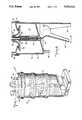
- FIG. 1is a perspective view of a fluid collection reservoir, particularly suitable for collecting blood, in accordance with the principles of the present invention, illustrating a general overall view of the reservoir.
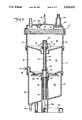
- FIG. 2is an enlarged cross-sectional view taken along line 2--2 of the reservoir depicted in FIG. 1 and showing the reservoir in a first fluid collecting operation.
- FIG. 3is a view like that of FIG. 2 but showing an isolation and holding of previously collected fluid while additional fluid is being collected.
- FIG. 4is a view like that depicted in FIGS. 2 and 3 but showing the reservoir transferring fluid previously isolated and delivering fluid out of the reservoir while simultaneously collecting additional fluid.
- FIG. 5is similar to FIG. 4 but showing an empty and segregated fluid isolation chamber.
- FIG. 6is a view substantially as the fluid collecting operation depicted in FIG. 2 but while also depicting the simultaneous delivery of fluid out of the reservoir.
- FIG. 7is substantially the illustration provided in FIG. 3 but also showing the simultaneous delivery of fluid out of the reservoir.
- FIG. 8is a view of the lower portion of the reservoir depicting an alternate configuration for reservoir activation.
- FIG. 9is a view of another reservoir construction, the view being similar to FIG. 2 but without fluid collection, showing a modified internal reservoir activation mechanism.
- FIG. 1there is illustrated a perspective view of blood collection reservoir 10 of the present invention depicting a general view of the reservoir. It should be understood that, while a blood collection reservoir will be described, the reservoir would be suitable for collection of other fluids.
- Reservoir 10includes rigid housing portion 12, blood inlet port 14, vacuum port 16, collection chamber 18 having compartments 20, 22 and 24, blood outlet port 26 and hanger 28.
- FIG. 2shows the reservoir schematically in a first blood collection step, with blood B shown entering inlet 14 upon the imposition of a vacuum V through vacuum port 16.
- Inlet 14is connected to a blood source and vacuum port 16 is connected to a suitable source of suction.
- Compartments 20 and 22are in fluid flow communication, both compartments being under vacuum, through a central opening through which the blood flows into compartment 22 for collection. Compartments 22 and 24 are sealed off from one another by means of valve 30 which forms a fluid tight seal between the two compartments. Valve 30 is held closed by spring 32, which is under compression, causing the seating of the valve and sealing of a central opening between compartment 22 and 24. Also shown in FIG. 2 is lever 34 engaging elongated member or rod 36 (the upper portion in this view being coupled to the lower portion by spring 38), spring 40 and valve 42 being supported by member 36. Additionally provided are filter 44, used for gross particulate removal and foam reduction, and baffle 46 which serves to divert blood away from vacuum port 16 to keep blood from exiting through the vacuum port.
- filter 44used for gross particulate removal and foam reduction
- baffle 46which serves to divert blood away from vacuum port 16 to keep blood from exiting through the vacuum port.
- a port 48which can serve to selectively pressurize compartment 24 as shown by P.
- Pressurization Pcan be achieved by using a sphygmomanometer bulb, a pressure gauge, and tubing (all of which are not shown) communicating with port 48. Pressure is preferably maintained from about atmospheric up to about 200 millimeters of mercury. Pressurizing air or gas entering compartment 24 through port 48 may be filtered using a bacterial filter (not shown) having a pore size less than one micron but preferably a pore size equal to or less than 0.45 microns. Alternatively, port 48 can be used to vent compartment 24 to atmosphere or ambient and, in this situation, a bacterial filter could also be used to prevent blood contamination. Lastly shown in FIG.
- seal rings 54close passageway 56 from vents 52 so that this path of communication between compartments 22 and 24, in addition to the compartmental sealing by valve 30, remains closed.
- the designis such that pressures between compartments 22 and 24 may be equalized through the displacement of seal rings 54 to open communication between vents 52 and channel 56 before valve 30 is unseated to open the larger central opening between the compartments. This equalization of pressure between compartments 22 and 24 is particularly important when compartment 24 is pressurized above atmospheric.
- FIG. 3there is shown lever 34 being moved downwardly, causing the downward displacement of member 36, and the downward movement of valve 42 which seats to seal compartments 20 and 22 from one another.
- Valve 30remains closed and blood is continuously being collected in compartment 20.
- FIG. 4depicts another step in the blood collection process wherein upon further downward movement of lever 34, member 36 is further displaced downwardly, spring 32 is further compressed and valve 30 is forced downwardly for unseating.
- the pressure equalization between compartments 22 and 24 through open vents 52 and passageway 56occurred after upper seal ring 54 passed vents 52 and before unseating of valve 30, with spring 38 being placed in tension and spring 40 being compressed.
- valve 30is unseated, releasing the previously established seal between compartments 22 and 24, and the blood previously collected and held in compartment 22 is allowed to flow into compartment 24. Meanwhile, valve 42 remains seated and blood continues to be collected in compartment 20. Also in this view, blood is shown exiting blood outlet port 26 while blood is simultaneously being collected. Pressurization of compartment 24 is accomplished to assist in the delivery of blood out of the reservoir. Alternatively, gravity delivery could have been employed.
- FIG. 5depicts the next sequence in the collection and delivery process wherein the direction of movement of lever 34 is reversed so that valve 30 is again seated to create a fluid seal between compartments 22 and 24.
- the energy stored in springs 32, 38 and 40assist lever 34 in this return direction.
- valve 42remains seated after the reseating of valve 30 and that blood continues to be simultaneously collected in compartment 20 while blood is delivered out of the reservoir through blood outlet port 26.
- FIG. 6shows the next collection and delivery sequence wherein lever 34 is returned to its starting location. Member 36 has moved upwardly (assisted by energy stored in compressed spring 40) and valve 42 is unseated for allowing blood collected in compartment 20 to flow into compartment 22. Valve 30 remains seated and blood continues to be drawn into and delivered out of reservoir 10.
- FIG. 7depicts the view substantially as that shown in FIG. 3 but additionally shows previously collected and transferred blood flowing out of compartment 24. The loop is now complete and the next step would be to repeat the FIG. 4 illustration.
- lever 34there is depicted a lever 34', which forms a finger grip, and extension 35, which can be placed in the palm of a hand, so that the movement of member 36 and operation of internal reservoir structure as heretofore described can be accomplished by moving lever 34' in the directions indicated by the arrows. Counterclockwise movement of lever 34' performs the functions achieved through the downward movement of lever 34. Likewise, the return clockwise movement of lever 34' achieves the functional result of moving lever 34 upwardly.
- FIG. 9there is shown the structure of reservoir 10 much like that depicted in FIGS. 2-7.
- reservoir 10'we have designated the reservoir 10' and the different structural features depicted are valve 42', valve guide ribs 41 and seal ring 43.
- Spring 38has been eliminated and elongated member 36 is continuous from lever 34 to valve 42' which is secured to member 36. Movement of valve 42', upon activation of lever 34 as heretofore described, is shown by the arrows. Upon deflection of lever 34, valve 42' moves downwardly and seal ring 43 creates a fluid seal between compartments 20 and 22.
- the movement of parts, collection and transfer of blood and delivery of blood out of reservoir 10'are as described in respect to reservoir 10. Additional features depicted in this view are ball float valve 58 (designed to prevent blood flow out of vacuum port 16) and medication port 60 (included so that medicine may be added to the blood if desired).
- a method of blood collectioncan be accomplished using either a patient or a reservoir as a blood source and collecting blood into and delivery out of the above-described inventive reservoir for conveyance of the collected blood to either the patient or a reservoir. Operation of the inventive reservoir would be as previously described.
- the reservoir herein disclosedis so designed that preferably the blood flow path through the reservoir is as shown in the drawing figures.
Landscapes
- Health & Medical Sciences (AREA)
- Heart & Thoracic Surgery (AREA)
- Vascular Medicine (AREA)
- Biomedical Technology (AREA)
- Engineering & Computer Science (AREA)
- Anesthesiology (AREA)
- Cardiology (AREA)
- Hematology (AREA)
- Life Sciences & Earth Sciences (AREA)
- Animal Behavior & Ethology (AREA)
- General Health & Medical Sciences (AREA)
- Public Health (AREA)
- Veterinary Medicine (AREA)
- External Artificial Organs (AREA)
Abstract
Description
Claims (16)
Priority Applications (1)
| Application Number | Priority Date | Filing Date | Title |
|---|---|---|---|
| US07/515,397US5024613A (en) | 1988-07-18 | 1990-04-27 | Blood recovery system and method |
Applications Claiming Priority (2)
| Application Number | Priority Date | Filing Date | Title |
|---|---|---|---|
| US07/220,193US4923438A (en) | 1988-07-18 | 1988-07-18 | Blood recovery system and method |
| US07/515,397US5024613A (en) | 1988-07-18 | 1990-04-27 | Blood recovery system and method |
Related Parent Applications (1)
| Application Number | Title | Priority Date | Filing Date |
|---|---|---|---|
| US07/220,193DivisionUS4923438A (en) | 1988-07-18 | 1988-07-18 | Blood recovery system and method |
Publications (1)
| Publication Number | Publication Date |
|---|---|
| US5024613Atrue US5024613A (en) | 1991-06-18 |
Family
ID=26914653
Family Applications (1)
| Application Number | Title | Priority Date | Filing Date |
|---|---|---|---|
| US07/515,397Expired - LifetimeUS5024613A (en) | 1988-07-18 | 1990-04-27 | Blood recovery system and method |
Country Status (1)
| Country | Link |
|---|---|
| US (1) | US5024613A (en) |
Cited By (63)
| Publication number | Priority date | Publication date | Assignee | Title |
|---|---|---|---|---|
| US5167621A (en)* | 1989-01-26 | 1992-12-01 | Surgicraft Limited | Fluid extractors |
| WO1992022347A1 (en)* | 1991-06-11 | 1992-12-23 | Deknatel Technology Corporation | Collection device |
| US5192439A (en)* | 1992-02-03 | 1993-03-09 | Electromedics, Inc. | Blood collection reservoir and filter device |
| US5286262A (en)* | 1987-03-02 | 1994-02-15 | Atrium Medical Corp. | Multipurpose collection vessel |
| USD347891S (en) | 1992-02-18 | 1994-06-14 | Bard AutoTransfusion Acquisition Corp. | Blood drainage system |
| US5387204A (en)* | 1991-02-01 | 1995-02-07 | Medical Projects Hb | Method and apparatus for dosing an additive at collection of liquid |
| US5462716A (en)* | 1991-11-11 | 1995-10-31 | Holm; Niels E. | Container for receiving and separating a fluid, preferably blood plasma, into its ingredients |
| US5480378A (en)* | 1990-05-14 | 1996-01-02 | Weis-Fogh; Ulla | Apparatus for preparing a concentrate of coagulation factors from a blood sample |
| US5634893A (en)* | 1995-04-24 | 1997-06-03 | Haemonetics Corporation | Autotransfusion apparatus |
| US5925025A (en)* | 1996-06-05 | 1999-07-20 | Tyco Group S.A.R.L. | Filtration valve cap with reflux clearing feature and related method of use thereof |
| US5931822A (en)* | 1993-06-08 | 1999-08-03 | Bemis Manufacturing Company | Medical suction system |
| US5975096A (en)* | 1996-08-16 | 1999-11-02 | Dornoch Medical Systems, Inc. | Liquid waste disposal and canister flushing system and method |
| US6017493A (en)* | 1997-09-26 | 2000-01-25 | Baxter International Inc. | Vacuum-assisted venous drainage reservoir for CPB systems |
| US6099493A (en)* | 1997-05-06 | 2000-08-08 | Sherwood Services, Ag | Continuous autotransfusion filtration system |
| US6217544B1 (en) | 1997-05-30 | 2001-04-17 | Sherwood Services, Ag | Filtration valve cap with reflux clearing feature and related method of use thereof |
| US6244311B1 (en) | 1994-12-29 | 2001-06-12 | Bemis Manufacturing Company | Method and apparatus for removing and disposing of body fluids |
| US6263887B1 (en) | 2000-01-14 | 2001-07-24 | Dornoch Medical Systems, Inc. | Liquid waste disposal and canister flushing system and method |
| US6315751B1 (en) | 1997-08-15 | 2001-11-13 | Cleveland Clinic Foundation | Cardiopulmonary bypass system using vacuum assisted venous drainage |
| US6322546B1 (en)* | 1999-10-28 | 2001-11-27 | Jostra Bentley Inc. | Fluid control conduit |
| US6358232B1 (en) | 1994-12-29 | 2002-03-19 | Bemis Manufacturing Company | Method and apparatus for removing and disposing of body fluids |
| US6478774B1 (en)* | 1999-11-18 | 2002-11-12 | Eurosets S.R.L. | Device for postoperative autotransfusion, particularly in heart surgery |
| US6626877B2 (en) | 2000-03-28 | 2003-09-30 | Bemis Manufacturing Company | Medical suction apparatus and methods for draining same |
| US6672477B2 (en) | 2001-01-12 | 2004-01-06 | Bemis Manufacturing Company | Method and apparatus for disposing of bodily fluids from a container |
| US20040143228A1 (en)* | 2000-03-28 | 2004-07-22 | Bemis Manufacturing Company | Medical suction apparatus and methods for draining same |
| US20040204693A1 (en)* | 2000-03-28 | 2004-10-14 | Bemis Manufacturing Company | Medical suction apparatus and draining of same |
| US20050101922A1 (en)* | 2003-11-07 | 2005-05-12 | Bemis Manufacturing Company | Suction canister and drainage of same |
| WO2006041406A1 (en)* | 2004-10-14 | 2006-04-20 | Astra Tech Ab | Method and apparatus for autotransfusion |
| US20060278588A1 (en)* | 2002-05-24 | 2006-12-14 | Woodell-May Jennifer E | Apparatus and method for separating and concentrating fluids containing multiple components |
| USD539899S1 (en)* | 2004-10-14 | 2007-04-03 | Astra Tech Ab | Blood recovery unit |
| US20070075016A1 (en)* | 2005-08-23 | 2007-04-05 | Biomet Manufacturing Corp. | Method and apparatus for collecting biological materials |
| US20070208321A1 (en)* | 2005-08-23 | 2007-09-06 | Biomet Manufacturing Corp. | Method And Apparatus For Collecting Biological Materials |
| RU2321429C1 (en)* | 2006-07-27 | 2008-04-10 | Общество с ограниченной ответственностью "Научно-технический центр "Мепотекс" | Blood collection and retransfusion apparatus |
| RU2321430C1 (en)* | 2006-07-27 | 2008-04-10 | Общество с ограниченной ответственностью "Научно-технический центр "Мепотекс" | Blood collection and retransfusion apparatus |
| US7374678B2 (en) | 2002-05-24 | 2008-05-20 | Biomet Biologics, Inc. | Apparatus and method for separating and concentrating fluids containing multiple components |
| RU2335302C2 (en)* | 2006-07-27 | 2008-10-10 | Общество с ограниченной ответственностью "Научно-технический центр "Мепотекс" | Device for recovery and reinfusion of blood |
| US7470371B2 (en) | 2002-05-03 | 2008-12-30 | Hanuman Llc | Methods and apparatus for isolating platelets from blood |
| US7780860B2 (en) | 2002-05-24 | 2010-08-24 | Biomet Biologics, Llc | Apparatus and method for separating and concentrating fluids containing multiple components |
| US7806276B2 (en) | 2007-04-12 | 2010-10-05 | Hanuman, Llc | Buoy suspension fractionation system |
| US7832566B2 (en) | 2002-05-24 | 2010-11-16 | Biomet Biologics, Llc | Method and apparatus for separating and concentrating a component from a multi-component material including macroparticles |
| US7845499B2 (en) | 2002-05-24 | 2010-12-07 | Biomet Biologics, Llc | Apparatus and method for separating and concentrating fluids containing multiple components |
| US7992725B2 (en) | 2002-05-03 | 2011-08-09 | Biomet Biologics, Llc | Buoy suspension fractionation system |
| US20120027519A1 (en)* | 2010-06-21 | 2012-02-02 | Krecke Edmond D | Method and a device for sealing and/or securing a borehole |
| US8313954B2 (en) | 2009-04-03 | 2012-11-20 | Biomet Biologics, Llc | All-in-one means of separating blood components |
| US8328024B2 (en) | 2007-04-12 | 2012-12-11 | Hanuman, Llc | Buoy suspension fractionation system |
| US8337711B2 (en) | 2008-02-29 | 2012-12-25 | Biomet Biologics, Llc | System and process for separating a material |
| US8567609B2 (en) | 2006-05-25 | 2013-10-29 | Biomet Biologics, Llc | Apparatus and method for separating and concentrating fluids containing multiple components |
| US8591391B2 (en) | 2010-04-12 | 2013-11-26 | Biomet Biologics, Llc | Method and apparatus for separating a material |
| US8783470B2 (en) | 2009-03-06 | 2014-07-22 | Biomet Biologics, Llc | Method and apparatus for producing autologous thrombin |
| US9011800B2 (en) | 2009-07-16 | 2015-04-21 | Biomet Biologics, Llc | Method and apparatus for separating biological materials |
| US9556243B2 (en) | 2013-03-15 | 2017-01-31 | Biomet Biologies, LLC | Methods for making cytokine compositions from tissues using non-centrifugal methods |
| US9642956B2 (en) | 2012-08-27 | 2017-05-09 | Biomet Biologics, Llc | Apparatus and method for separating and concentrating fluids containing multiple components |
| US9701728B2 (en) | 2008-02-27 | 2017-07-11 | Biomet Biologics, Llc | Methods and compositions for delivering interleukin-1 receptor antagonist |
| US9867939B2 (en)* | 2013-03-12 | 2018-01-16 | Allergan, Inc. | Adipose tissue combinations, devices, and uses thereof |
| US9895418B2 (en) | 2013-03-15 | 2018-02-20 | Biomet Biologics, Llc | Treatment of peripheral vascular disease using protein solutions |
| US9950035B2 (en) | 2013-03-15 | 2018-04-24 | Biomet Biologics, Llc | Methods and non-immunogenic compositions for treating inflammatory disorders |
| US10143725B2 (en) | 2013-03-15 | 2018-12-04 | Biomet Biologics, Llc | Treatment of pain using protein solutions |
| US10265477B2 (en) | 2013-05-23 | 2019-04-23 | Allergan, Inc. | Mechanical syringe accessory |
| CN109893687A (en)* | 2019-02-18 | 2019-06-18 | 美昕医疗器械(上海)有限公司 | A kind of waste collecting device and waste gathering processing system |
| CN109999229A (en)* | 2019-03-14 | 2019-07-12 | 美昕医疗器械(上海)有限公司 | A kind of waste collecting device and waste gathering processing system |
| US10433928B2 (en) | 2015-03-10 | 2019-10-08 | Allergan Pharmaceuticals Holdings (Ireland) Unlimited Company | Multiple needle injector |
| US10576130B2 (en) | 2013-03-15 | 2020-03-03 | Biomet Manufacturing, Llc | Treatment of collagen defects using protein solutions |
| US10596321B2 (en) | 2016-04-08 | 2020-03-24 | Allergan, Inc. | Aspiration and injection device |
| US10792427B2 (en) | 2014-05-13 | 2020-10-06 | Allergan, Inc. | High force injection devices |
Citations (7)
| Publication number | Priority date | Publication date | Assignee | Title |
|---|---|---|---|---|
| US2745111A (en)* | 1953-05-13 | 1956-05-15 | Air Associates Inc | Personal relief device |
| US2759476A (en)* | 1954-12-08 | 1956-08-21 | Gomco Surgical Mfg Corp | Aspirating apparatus |
| US3585995A (en)* | 1968-09-03 | 1971-06-22 | George D Perkins | Autotransfusion apparatus |
| US3896733A (en)* | 1973-10-18 | 1975-07-29 | Pall Corp | Autotransfusion apparatus |
| US4006745A (en)* | 1975-05-22 | 1977-02-08 | Sorenson Research Co., Inc. | Autologous transfusion system and method |
| US4033345A (en)* | 1975-11-13 | 1977-07-05 | Sorenson Research Co., Inc. | Autologous transfusion filter system and method |
| US4047526A (en)* | 1975-05-22 | 1977-09-13 | Sorenson Research Co., Inc. | Autologous blood system and method |
- 1990
- 1990-04-27USUS07/515,397patent/US5024613A/ennot_activeExpired - Lifetime
Patent Citations (7)
| Publication number | Priority date | Publication date | Assignee | Title |
|---|---|---|---|---|
| US2745111A (en)* | 1953-05-13 | 1956-05-15 | Air Associates Inc | Personal relief device |
| US2759476A (en)* | 1954-12-08 | 1956-08-21 | Gomco Surgical Mfg Corp | Aspirating apparatus |
| US3585995A (en)* | 1968-09-03 | 1971-06-22 | George D Perkins | Autotransfusion apparatus |
| US3896733A (en)* | 1973-10-18 | 1975-07-29 | Pall Corp | Autotransfusion apparatus |
| US4006745A (en)* | 1975-05-22 | 1977-02-08 | Sorenson Research Co., Inc. | Autologous transfusion system and method |
| US4047526A (en)* | 1975-05-22 | 1977-09-13 | Sorenson Research Co., Inc. | Autologous blood system and method |
| US4033345A (en)* | 1975-11-13 | 1977-07-05 | Sorenson Research Co., Inc. | Autologous transfusion filter system and method |
Cited By (119)
| Publication number | Priority date | Publication date | Assignee | Title |
|---|---|---|---|---|
| US5286262A (en)* | 1987-03-02 | 1994-02-15 | Atrium Medical Corp. | Multipurpose collection vessel |
| US5167621A (en)* | 1989-01-26 | 1992-12-01 | Surgicraft Limited | Fluid extractors |
| US5480378A (en)* | 1990-05-14 | 1996-01-02 | Weis-Fogh; Ulla | Apparatus for preparing a concentrate of coagulation factors from a blood sample |
| US5387204A (en)* | 1991-02-01 | 1995-02-07 | Medical Projects Hb | Method and apparatus for dosing an additive at collection of liquid |
| WO1992022347A1 (en)* | 1991-06-11 | 1992-12-23 | Deknatel Technology Corporation | Collection device |
| US5318510A (en)* | 1991-06-11 | 1994-06-07 | Deknatel Technology Corporation, Inc. | Collection device |
| US5746979A (en)* | 1991-11-11 | 1998-05-05 | F. R, Squibb & Sons, Inc. | Method for receiving and separating a fluid into its ingredients |
| US5462716A (en)* | 1991-11-11 | 1995-10-31 | Holm; Niels E. | Container for receiving and separating a fluid, preferably blood plasma, into its ingredients |
| US5658533A (en)* | 1991-11-11 | 1997-08-19 | E.R. Squibb & Sons, Inc. | Container for receiving and separating a fluid into its ingredients |
| US5674458A (en)* | 1991-11-11 | 1997-10-07 | E. R. Squibb & Sons, Inc. | Container for receiving and separating a fluid into its ingredients |
| US5192439A (en)* | 1992-02-03 | 1993-03-09 | Electromedics, Inc. | Blood collection reservoir and filter device |
| USD347891S (en) | 1992-02-18 | 1994-06-14 | Bard AutoTransfusion Acquisition Corp. | Blood drainage system |
| US6673055B2 (en) | 1993-06-08 | 2004-01-06 | Bemis Manufacturing Company | Medical suction system |
| US5931822A (en)* | 1993-06-08 | 1999-08-03 | Bemis Manufacturing Company | Medical suction system |
| US7115115B2 (en) | 1993-06-08 | 2006-10-03 | Bemis Manufacturing Company | Medical suction system |
| US6368310B1 (en) | 1993-06-08 | 2002-04-09 | Bemis Manufacturing Company | Medical suction system |
| US6494869B1 (en) | 1994-12-29 | 2002-12-17 | Bemis Manufacturing Company | Method and apparatus for removing and disposing of body fluids |
| US6244311B1 (en) | 1994-12-29 | 2001-06-12 | Bemis Manufacturing Company | Method and apparatus for removing and disposing of body fluids |
| US6358232B1 (en) | 1994-12-29 | 2002-03-19 | Bemis Manufacturing Company | Method and apparatus for removing and disposing of body fluids |
| US5634893A (en)* | 1995-04-24 | 1997-06-03 | Haemonetics Corporation | Autotransfusion apparatus |
| US6558341B1 (en) | 1996-05-07 | 2003-05-06 | Sherwood Services, Ag | Continuous autotransfusion filtration system |
| US5925025A (en)* | 1996-06-05 | 1999-07-20 | Tyco Group S.A.R.L. | Filtration valve cap with reflux clearing feature and related method of use thereof |
| US5975096A (en)* | 1996-08-16 | 1999-11-02 | Dornoch Medical Systems, Inc. | Liquid waste disposal and canister flushing system and method |
| US6099493A (en)* | 1997-05-06 | 2000-08-08 | Sherwood Services, Ag | Continuous autotransfusion filtration system |
| US6217544B1 (en) | 1997-05-30 | 2001-04-17 | Sherwood Services, Ag | Filtration valve cap with reflux clearing feature and related method of use thereof |
| US6315751B1 (en) | 1997-08-15 | 2001-11-13 | Cleveland Clinic Foundation | Cardiopulmonary bypass system using vacuum assisted venous drainage |
| US6537495B1 (en) | 1997-09-26 | 2003-03-25 | Edwards Lifesciences Llc | Vacuum-assisted venous drainage system with rigid housing and flexible reservoir |
| US6017493A (en)* | 1997-09-26 | 2000-01-25 | Baxter International Inc. | Vacuum-assisted venous drainage reservoir for CPB systems |
| US6322546B1 (en)* | 1999-10-28 | 2001-11-27 | Jostra Bentley Inc. | Fluid control conduit |
| US6478774B1 (en)* | 1999-11-18 | 2002-11-12 | Eurosets S.R.L. | Device for postoperative autotransfusion, particularly in heart surgery |
| US6263887B1 (en) | 2000-01-14 | 2001-07-24 | Dornoch Medical Systems, Inc. | Liquid waste disposal and canister flushing system and method |
| US20040059303A1 (en)* | 2000-03-28 | 2004-03-25 | Bemis Manufacturing Company | Medical suction apparatus and methods for draining same |
| US20040143228A1 (en)* | 2000-03-28 | 2004-07-22 | Bemis Manufacturing Company | Medical suction apparatus and methods for draining same |
| US20040204693A1 (en)* | 2000-03-28 | 2004-10-14 | Bemis Manufacturing Company | Medical suction apparatus and draining of same |
| US6626877B2 (en) | 2000-03-28 | 2003-09-30 | Bemis Manufacturing Company | Medical suction apparatus and methods for draining same |
| US7674248B2 (en) | 2000-03-28 | 2010-03-09 | Bemis Manufacturing Company | Medical suction apparatus and methods for draining same |
| US7585292B2 (en) | 2000-03-28 | 2009-09-08 | Bemis Manufacturing Company | Medical suction apparatus and draining of same |
| US6672477B2 (en) | 2001-01-12 | 2004-01-06 | Bemis Manufacturing Company | Method and apparatus for disposing of bodily fluids from a container |
| US8950586B2 (en) | 2002-05-03 | 2015-02-10 | Hanuman Llc | Methods and apparatus for isolating platelets from blood |
| US8187477B2 (en) | 2002-05-03 | 2012-05-29 | Hanuman, Llc | Methods and apparatus for isolating platelets from blood |
| US7470371B2 (en) | 2002-05-03 | 2008-12-30 | Hanuman Llc | Methods and apparatus for isolating platelets from blood |
| US7992725B2 (en) | 2002-05-03 | 2011-08-09 | Biomet Biologics, Llc | Buoy suspension fractionation system |
| US7837884B2 (en) | 2002-05-03 | 2010-11-23 | Hanuman, Llc | Methods and apparatus for isolating platelets from blood |
| US7845499B2 (en) | 2002-05-24 | 2010-12-07 | Biomet Biologics, Llc | Apparatus and method for separating and concentrating fluids containing multiple components |
| US8163184B2 (en) | 2002-05-24 | 2012-04-24 | Biomet Biologics, Llc | Apparatus and method for separating and concentrating fluids containing multiple components |
| US7374678B2 (en) | 2002-05-24 | 2008-05-20 | Biomet Biologics, Inc. | Apparatus and method for separating and concentrating fluids containing multiple components |
| US8603346B2 (en) | 2002-05-24 | 2013-12-10 | Biomet Biologics, Llc | Apparatus and method for separating and concentrating fluids containing multiple components |
| US8808551B2 (en) | 2002-05-24 | 2014-08-19 | Biomet Biologics, Llc | Apparatus and method for separating and concentrating fluids containing multiple components |
| US20060278588A1 (en)* | 2002-05-24 | 2006-12-14 | Woodell-May Jennifer E | Apparatus and method for separating and concentrating fluids containing multiple components |
| US9114334B2 (en) | 2002-05-24 | 2015-08-25 | Biomet Biologics, Llc | Apparatus and method for separating and concentrating fluids containing multiple components |
| US7914689B2 (en) | 2002-05-24 | 2011-03-29 | Biomet Biologics, Llc | Apparatus and method for separating and concentrating fluids containing multiple components |
| US9897589B2 (en) | 2002-05-24 | 2018-02-20 | Biomet Biologics, Llc | Apparatus and method for separating and concentrating fluids containing multiple components |
| US10183042B2 (en) | 2002-05-24 | 2019-01-22 | Biomet Manufacturing, Llc | Apparatus and method for separating and concentrating fluids containing multiple components |
| US7780860B2 (en) | 2002-05-24 | 2010-08-24 | Biomet Biologics, Llc | Apparatus and method for separating and concentrating fluids containing multiple components |
| US10393728B2 (en) | 2002-05-24 | 2019-08-27 | Biomet Biologics, Llc | Apparatus and method for separating and concentrating fluids containing multiple components |
| US8062534B2 (en) | 2002-05-24 | 2011-11-22 | Biomet Biologics, Llc | Apparatus and method for separating and concentrating fluids containing multiple components |
| US7832566B2 (en) | 2002-05-24 | 2010-11-16 | Biomet Biologics, Llc | Method and apparatus for separating and concentrating a component from a multi-component material including macroparticles |
| US8048321B2 (en) | 2002-05-24 | 2011-11-01 | Biomet Biologics, Llc | Apparatus and method for separating and concentrating fluids containing multiple components |
| US20050101922A1 (en)* | 2003-11-07 | 2005-05-12 | Bemis Manufacturing Company | Suction canister and drainage of same |
| WO2006041406A1 (en)* | 2004-10-14 | 2006-04-20 | Astra Tech Ab | Method and apparatus for autotransfusion |
| US8241264B2 (en)* | 2004-10-14 | 2012-08-14 | Astra Tech Ab | Method and apparatus for autotransfusion |
| CN101039708B (en)* | 2004-10-14 | 2013-04-24 | 艾斯特勒科技公司 | Apparatus for autotransfusion |
| EP1799281A4 (en)* | 2004-10-14 | 2012-12-26 | Dentsply Ih Ab | Method and apparatus for autotransfusion |
| AU2005294813B2 (en)* | 2004-10-14 | 2009-08-06 | Astra Tech Ab | Apparatus for autotransfusion |
| USD539899S1 (en)* | 2004-10-14 | 2007-04-03 | Astra Tech Ab | Blood recovery unit |
| US20080015485A1 (en)* | 2004-10-14 | 2008-01-17 | Astra Tech Ab | Method and Apparatus For Autotransfusion |
| RU2391120C2 (en)* | 2004-10-14 | 2010-06-10 | Астра Тек АБ | Method and device for autotransfusion |
| US20100255977A1 (en)* | 2005-08-23 | 2010-10-07 | Biomet Manufacturing Corp. | Method and Apparatus for Collecting Biological Materials |
| US8236258B2 (en) | 2005-08-23 | 2012-08-07 | Biomet Biologics, Llc | Method and apparatus for collecting biological materials |
| US20070208321A1 (en)* | 2005-08-23 | 2007-09-06 | Biomet Manufacturing Corp. | Method And Apparatus For Collecting Biological Materials |
| US7771590B2 (en) | 2005-08-23 | 2010-08-10 | Biomet Manufacturing Corp. | Method and apparatus for collecting biological materials |
| US20070075016A1 (en)* | 2005-08-23 | 2007-04-05 | Biomet Manufacturing Corp. | Method and apparatus for collecting biological materials |
| US8048297B2 (en) | 2005-08-23 | 2011-11-01 | Biomet Biologics, Llc | Method and apparatus for collecting biological materials |
| US8048320B2 (en) | 2005-08-23 | 2011-11-01 | Biomet Manufacturing Corp. | Method and apparatus for collecting biological materials |
| US8512575B2 (en) | 2005-08-23 | 2013-08-20 | Biomet Biologics, Llc | Method and apparatus for collecting biological materials |
| US8567609B2 (en) | 2006-05-25 | 2013-10-29 | Biomet Biologics, Llc | Apparatus and method for separating and concentrating fluids containing multiple components |
| RU2321430C1 (en)* | 2006-07-27 | 2008-04-10 | Общество с ограниченной ответственностью "Научно-технический центр "Мепотекс" | Blood collection and retransfusion apparatus |
| RU2321429C1 (en)* | 2006-07-27 | 2008-04-10 | Общество с ограниченной ответственностью "Научно-технический центр "Мепотекс" | Blood collection and retransfusion apparatus |
| RU2335302C2 (en)* | 2006-07-27 | 2008-10-10 | Общество с ограниченной ответственностью "Научно-технический центр "Мепотекс" | Device for recovery and reinfusion of blood |
| US8596470B2 (en) | 2007-04-12 | 2013-12-03 | Hanuman, Llc | Buoy fractionation system |
| US8119013B2 (en) | 2007-04-12 | 2012-02-21 | Hanuman, Llc | Method of separating a selected component from a multiple component material |
| US7806276B2 (en) | 2007-04-12 | 2010-10-05 | Hanuman, Llc | Buoy suspension fractionation system |
| US9649579B2 (en) | 2007-04-12 | 2017-05-16 | Hanuman Llc | Buoy suspension fractionation system |
| US9138664B2 (en) | 2007-04-12 | 2015-09-22 | Biomet Biologics, Llc | Buoy fractionation system |
| US8328024B2 (en) | 2007-04-12 | 2012-12-11 | Hanuman, Llc | Buoy suspension fractionation system |
| US11725031B2 (en) | 2008-02-27 | 2023-08-15 | Biomet Manufacturing, Llc | Methods and compositions for delivering interleukin-1 receptor antagonist |
| US10400017B2 (en) | 2008-02-27 | 2019-09-03 | Biomet Biologics, Llc | Methods and compositions for delivering interleukin-1 receptor antagonist |
| US9701728B2 (en) | 2008-02-27 | 2017-07-11 | Biomet Biologics, Llc | Methods and compositions for delivering interleukin-1 receptor antagonist |
| US9719063B2 (en) | 2008-02-29 | 2017-08-01 | Biomet Biologics, Llc | System and process for separating a material |
| US8337711B2 (en) | 2008-02-29 | 2012-12-25 | Biomet Biologics, Llc | System and process for separating a material |
| US8801586B2 (en)* | 2008-02-29 | 2014-08-12 | Biomet Biologics, Llc | System and process for separating a material |
| US8783470B2 (en) | 2009-03-06 | 2014-07-22 | Biomet Biologics, Llc | Method and apparatus for producing autologous thrombin |
| US8313954B2 (en) | 2009-04-03 | 2012-11-20 | Biomet Biologics, Llc | All-in-one means of separating blood components |
| US8992862B2 (en) | 2009-04-03 | 2015-03-31 | Biomet Biologics, Llc | All-in-one means of separating blood components |
| US9011800B2 (en) | 2009-07-16 | 2015-04-21 | Biomet Biologics, Llc | Method and apparatus for separating biological materials |
| US9533090B2 (en) | 2010-04-12 | 2017-01-03 | Biomet Biologics, Llc | Method and apparatus for separating a material |
| US8591391B2 (en) | 2010-04-12 | 2013-11-26 | Biomet Biologics, Llc | Method and apparatus for separating a material |
| US20120027519A1 (en)* | 2010-06-21 | 2012-02-02 | Krecke Edmond D | Method and a device for sealing and/or securing a borehole |
| US8888407B2 (en)* | 2010-06-21 | 2014-11-18 | Edmond D. Krecke | Method and a device for sealing and/or securing a borehole |
| US9239276B2 (en) | 2011-04-19 | 2016-01-19 | Biomet Biologics, Llc | Apparatus and method for separating and concentrating fluids containing multiple components |
| US9642956B2 (en) | 2012-08-27 | 2017-05-09 | Biomet Biologics, Llc | Apparatus and method for separating and concentrating fluids containing multiple components |
| US9867939B2 (en)* | 2013-03-12 | 2018-01-16 | Allergan, Inc. | Adipose tissue combinations, devices, and uses thereof |
| US10143725B2 (en) | 2013-03-15 | 2018-12-04 | Biomet Biologics, Llc | Treatment of pain using protein solutions |
| US10576130B2 (en) | 2013-03-15 | 2020-03-03 | Biomet Manufacturing, Llc | Treatment of collagen defects using protein solutions |
| US11957733B2 (en) | 2013-03-15 | 2024-04-16 | Biomet Manufacturing, Llc | Treatment of collagen defects using protein solutions |
| US9556243B2 (en) | 2013-03-15 | 2017-01-31 | Biomet Biologies, LLC | Methods for making cytokine compositions from tissues using non-centrifugal methods |
| US10208095B2 (en) | 2013-03-15 | 2019-02-19 | Biomet Manufacturing, Llc | Methods for making cytokine compositions from tissues using non-centrifugal methods |
| US9950035B2 (en) | 2013-03-15 | 2018-04-24 | Biomet Biologics, Llc | Methods and non-immunogenic compositions for treating inflammatory disorders |
| US9895418B2 (en) | 2013-03-15 | 2018-02-20 | Biomet Biologics, Llc | Treatment of peripheral vascular disease using protein solutions |
| US10441634B2 (en) | 2013-03-15 | 2019-10-15 | Biomet Biologics, Llc | Treatment of peripheral vascular disease using protein solutions |
| US10265477B2 (en) | 2013-05-23 | 2019-04-23 | Allergan, Inc. | Mechanical syringe accessory |
| US10792427B2 (en) | 2014-05-13 | 2020-10-06 | Allergan, Inc. | High force injection devices |
| US10433928B2 (en) | 2015-03-10 | 2019-10-08 | Allergan Pharmaceuticals Holdings (Ireland) Unlimited Company | Multiple needle injector |
| US10596321B2 (en) | 2016-04-08 | 2020-03-24 | Allergan, Inc. | Aspiration and injection device |
| US11890457B2 (en) | 2016-04-08 | 2024-02-06 | Allergan, Inc. | Aspiration and injection device |
| CN109893687A (en)* | 2019-02-18 | 2019-06-18 | 美昕医疗器械(上海)有限公司 | A kind of waste collecting device and waste gathering processing system |
| CN109893687B (en)* | 2019-02-18 | 2024-04-09 | 美昕医疗器械(上海)有限公司 | Waste collection equipment and waste collection treatment system |
| CN109999229A (en)* | 2019-03-14 | 2019-07-12 | 美昕医疗器械(上海)有限公司 | A kind of waste collecting device and waste gathering processing system |
| WO2020182198A1 (en)* | 2019-03-14 | 2020-09-17 | 美昕医疗器械(上海)有限公司 | Waste collection apparatus and waste collection and treatment system |
Similar Documents
| Publication | Publication Date | Title |
|---|---|---|
| US5024613A (en) | Blood recovery system and method | |
| US4923438A (en) | Blood recovery system and method | |
| US4781707A (en) | Process and apparatus for collecting blood from a body cavity for autotransfusion | |
| US11944782B2 (en) | Priming apparatus and method | |
| US4006745A (en) | Autologous transfusion system and method | |
| US6336916B1 (en) | Priming system | |
| US4047526A (en) | Autologous blood system and method | |
| US5207638A (en) | Blood transfer apparatus | |
| US5279550A (en) | Orthopedic autotransfusion system | |
| US5738796A (en) | Method for separating components from a biological fluid | |
| AU739115B2 (en) | Biological fluid filtration method and apparatus | |
| US5074839A (en) | Blood transfer apparatus | |
| EP0455215A2 (en) | Blood collection device | |
| JPS59186561A (en) | Blood dehydrating apparatus | |
| WO1991017790A1 (en) | Method, apparatus for delivering or withdrawing fluid | |
| US20030144646A1 (en) | Method and apparatus for collecting and transporting liquid | |
| US5554293A (en) | Disposable blood washing and apheresis device and method of using thereof | |
| US4834743A (en) | Autologous transfusion system and apparatus | |
| US7910008B2 (en) | Sealed sterile system and method for filtering biological or medical fluids, in particular whole blood | |
| JP2001527430A (en) | Drainage device with feature to reduce and control negative pressure | |
| CA2425865C (en) | Drainage unit with controlled negativity relief feature | |
| EP0074291B1 (en) | Air purge unit for autotransfusion apparatus and autotransfusion apparatus comprising the same |
Legal Events
| Date | Code | Title | Description |
|---|---|---|---|
| FEPP | Fee payment procedure | Free format text:PAYOR NUMBER ASSIGNED (ORIGINAL EVENT CODE: ASPN); ENTITY STATUS OF PATENT OWNER: LARGE ENTITY | |
| STCF | Information on status: patent grant | Free format text:PATENTED CASE | |
| AS | Assignment | Owner name:BANQUE PARIBAS Free format text:SECURITY INTEREST;ASSIGNOR:DEKNATEL TECHNOLOGY CORPORATION, A CORP. OF DE;REEL/FRAME:005921/0658 Effective date:19911120 | |
| FEPP | Fee payment procedure | Free format text:PAYER NUMBER DE-ASSIGNED (ORIGINAL EVENT CODE: RMPN); ENTITY STATUS OF PATENT OWNER: LARGE ENTITY Free format text:PAYOR NUMBER ASSIGNED (ORIGINAL EVENT CODE: ASPN); ENTITY STATUS OF PATENT OWNER: LARGE ENTITY | |
| AS | Assignment | Owner name:DEKNATEL TECHNOLOGY CORPORATION A CORP. OF DE, NE Free format text:ASSIGNMENT OF ASSIGNORS INTEREST.;ASSIGNOR:PFIZER HOSPITAL PRODUCTS GROUP, INC., A CORP. OF DE;REEL/FRAME:005949/0166 Effective date:19911119 | |
| AS | Assignment | Owner name:DEKNATEL TECHNOLOGY CORPORATION A CORPORATION OF Free format text:ASSIGNMENT OF ASSIGNORS INTEREST.;ASSIGNOR:PFIZER HOSPITAL PRODUCTS GROUP, INC., A CORPORATION OF DE;REEL/FRAME:006073/0874 Effective date:19911122 | |
| FPAY | Fee payment | Year of fee payment:4 | |
| FPAY | Fee payment | Year of fee payment:8 | |
| FEPP | Fee payment procedure | Free format text:PAYER NUMBER DE-ASSIGNED (ORIGINAL EVENT CODE: RMPN); ENTITY STATUS OF PATENT OWNER: LARGE ENTITY Free format text:PAYOR NUMBER ASSIGNED (ORIGINAL EVENT CODE: ASPN); ENTITY STATUS OF PATENT OWNER: LARGE ENTITY | |
| AS | Assignment | Owner name:GENZYME CORPORATION, MASSACHUSETTS Free format text:ASSIGNMENT OF ASSIGNORS INTEREST;ASSIGNOR:DEKNATEL TECHNOLOGY CORPORATION;REEL/FRAME:012435/0953 Effective date:20011024 | |
| FPAY | Fee payment | Year of fee payment:12 | |
| AS | Assignment | Owner name:TELEFLEX-CT DEVICES INCORPORATED, PENNSYLVANIA Free format text:ASSIGNMENT OF ASSIGNORS INTEREST;ASSIGNOR:GENZYME CORPORATION;REEL/FRAME:014363/0776 Effective date:20030630 Owner name:TELEFLEX-CT DEVICES INCORPORATED,PENNSYLVANIA Free format text:ASSIGNMENT OF ASSIGNORS INTEREST;ASSIGNOR:GENZYME CORPORATION;REEL/FRAME:014363/0776 Effective date:20030630 | |
| AS | Assignment | Owner name:TECHNOLOGY HOLDING COMPANY II, DELAWARE Free format text:ASSIGNMENT OF ASSIGNORS INTEREST;ASSIGNOR:TELEFLEX-CT DEVICES INCORPORATED;REEL/FRAME:016059/0332 Effective date:20031217 | |
| FEPP | Fee payment procedure | Free format text:PAYOR NUMBER ASSIGNED (ORIGINAL EVENT CODE: ASPN); ENTITY STATUS OF PATENT OWNER: LARGE ENTITY Free format text:PAYER NUMBER DE-ASSIGNED (ORIGINAL EVENT CODE: RMPN); ENTITY STATUS OF PATENT OWNER: LARGE ENTITY |