US5024485A - Front and back adjustable rocking seat support arrangement for seat having relatively adjustable sections - Google Patents
Front and back adjustable rocking seat support arrangement for seat having relatively adjustable sectionsDownload PDFInfo
- Publication number
- US5024485A US5024485AUS07/548,267US54826790AUS5024485AUS 5024485 AUS5024485 AUS 5024485AUS 54826790 AUS54826790 AUS 54826790AUS 5024485 AUS5024485 AUS 5024485A
- Authority
- US
- United States
- Prior art keywords
- seat
- base
- rocking
- receiving means
- resilient receiving
- Prior art date
- Legal status (The legal status is an assumption and is not a legal conclusion. Google has not performed a legal analysis and makes no representation as to the accuracy of the status listed.)
- Expired - Fee Related
Links
- 239000011435rockSubstances0.000claimsabstractdescription21
- 125000006850spacer groupChemical group0.000claimsdescription18
- 239000000463materialSubstances0.000claimsdescription8
- 230000000712assemblyEffects0.000claimsdescription6
- 238000000429assemblyMethods0.000claimsdescription6
- 239000006260foamSubstances0.000claimsdescription6
- 230000000717retained effectEffects0.000claims3
- 239000002184metalSubstances0.000claims2
- 238000010276constructionMethods0.000description3
- 210000000988bone and boneAnatomy0.000description2
- 230000000295complement effectEffects0.000description2
- 230000004048modificationEffects0.000description2
- 238000012986modificationMethods0.000description2
- 230000002035prolonged effectEffects0.000description2
- 229910000639Spring steelInorganic materials0.000description1
- 230000004308accommodationEffects0.000description1
- 230000009286beneficial effectEffects0.000description1
- 230000000903blocking effectEffects0.000description1
- 238000003780insertionMethods0.000description1
- 230000037431insertionEffects0.000description1
- 239000003562lightweight materialSubstances0.000description1
- 239000002991molded plasticSubstances0.000description1
- 235000021178picnicNutrition0.000description1
- 239000012858resilient materialSubstances0.000description1
- 230000000153supplemental effectEffects0.000description1
Images

Classifications
- A—HUMAN NECESSITIES
- A47—FURNITURE; DOMESTIC ARTICLES OR APPLIANCES; COFFEE MILLS; SPICE MILLS; SUCTION CLEANERS IN GENERAL
- A47C—CHAIRS; SOFAS; BEDS
- A47C7/00—Parts, details, or accessories of chairs or stools
- A47C7/02—Seat parts
- A47C7/024—Seat parts with double seats
- A—HUMAN NECESSITIES
- A47—FURNITURE; DOMESTIC ARTICLES OR APPLIANCES; COFFEE MILLS; SPICE MILLS; SUCTION CLEANERS IN GENERAL
- A47C—CHAIRS; SOFAS; BEDS
- A47C3/00—Chairs characterised by structural features; Chairs or stools with rotatable or vertically-adjustable seats
- A47C3/02—Rocking chairs
- A47C3/025—Rocking chairs with seat, or seat and back-rest unit elastically or pivotally mounted in a rigid base frame
- A—HUMAN NECESSITIES
- A47—FURNITURE; DOMESTIC ARTICLES OR APPLIANCES; COFFEE MILLS; SPICE MILLS; SUCTION CLEANERS IN GENERAL
- A47C—CHAIRS; SOFAS; BEDS
- A47C9/00—Stools for specified purposes
- A47C9/002—Stools for specified purposes with exercising means or having special therapeutic or ergonomic effects
Definitions
- the present inventionrelates to the field of posture chairs which are various configurations for seating arrangements that are used to improve the posture of the individual by more efficiently supporting the weight of the individual who sits on the seat and adjusting the height of the seat sections to accommodate movement of the individual in the seat.
- the objectwas to provide a seat construction which readily responds to or accommodates itself to the position of the body of the person occupying it.
- the objectwas to provide a seat which was self-aligning and which was so constructed that it allowed each side of the body of the occupant of the seat to move normally and independently of the other without restraint.
- U.S. Pat. No. 2,799,323provided an embodiment with two separate seat halves which were independently supported by coil springs.
- U.S. Pat. No. 3,080,195was an improvement on U.S. Pat. No. 2,799,323 and comprises a seat having two independent halves wherein the flexibility is provided through a resilient cushion under each of the seat sections.
- U.S. Pat. No. 4,047,757discloses a seating unit with a flexible seat back having an upper portion separated into two halves positioned to support a user's back at opposite sides of his spine.
- U.S. Pat. No. 3,749,422was a substantial mechanical improvement on the concept embodied in the prior two U.S. Pat. Nos. 2,799,323 and 3,080,195.
- the inventioninvolved a seat assembly having a base and two complementary seat elements supported thereon. Each seat element was able to move independently of the other seating element. Each seat pad was supported by a universal joint support which permitted each seat to move in any tilting orientation to accommodate different positions of the user's body. Each seat element had recesses or apertures offset rearwardly from the universal connections for receiving the ischial tuberosity bones of the user, and the back of the seat had a localized recess for partial reception of the lumbar portion of the user's backbone.
- the U.S. Pat. No. 1,990,661 to Middletonrelates to a Vehicle Seat and is of interest as being disposed upon a plurality of spherical members 7.
- the spherical membersdo not have a front and back locking and rocking arrangement.
- U.S. Pat. No. 633,087 issued to Johnsonshows a chair including a seat F which may tilt forward and rearward.
- the mechanism which consists of an arc shape support block Gis different than the present invention arrangement.
- German Patent Publication issued in 1986shows a tilting chair of interest with respect to the Ball 6. However, the tilting is performed by a spring 7 and not by a locking and rocking arrangement.
- the present inventionis an improvement to the seat having relatively adjustable sections disclosed and claimed in U.S. Pat. No. 3,749,442 to restrict the movement of each separate seat section to movement only back and forth in a longitudinal rocking motion as opposed to universal movement, to thereby more effectively and efficiently assist in the comfort of the individual and adjustment of the seat to movements of the user without causing undue fatigue over time.
- the improvementcomprises a seat rocking means such as a cylindrical rod affixed to the lower portion of each seat half and a pair of spaced apart resilient receiving means for each seat half to movably and rotatably support a seat half on the base of the seat.
- the resilience of the receiving meanspermits the seat rooking means to vertically move downward within the receiving means when a force such as the weight of a person pushes downward on the seat.
- the resilience of the receiving meansfurther permits the seat rocking means to rock back and forth to thereby enable the user to independently rock back and forth in a front to back rocking arrangement on each seat half.
- the present inventionfurther comprises an adjustable device to limit the amount of front to back rocking which can be created.
- FIG. 1is a perspective view of the present invention front and back rocking seat support arrangement for seat having relatively adjustable sections.
- FIG. 2is a cross-sectional view taken along line 2--2 of FIG. 1.
- FIG. 3is a cross-sectional view taken along line 3--3 of FIG. 1.
- FIG. 4is a plan view of the underside of each movable seat half, disclosing the seat rocking means attached to the underside of each seat half.
- FIG. 5is a plan view of the seat body, disclosing the cushioning members and the resilient receiving members for both movable seat halves.
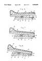
- FIG. 6is a cross-sectional view of the seat base, a rocking seat half, and the rocking adjustment means positioned in the half rock position.
- FIG. 7is a cross-sectional view of the seat base, a rocking seat half, and the rocking adjustment means positioned in the locked non-rocking position.
- FIG. 8is a cross-sectional view of the seat base, a rocking seat half, and the rocking adjustment means positioned in the maximum rock position.
- the seat assemblywhich includes a seat body 12 to which two complementary seat cushion assemblies 60 and 70 are mounted for limited individual adjustable rocking movement.
- the seat body 12further comprises a rigid base 14 and a pair of spaced apart resilient spacer members, a front spacer member 16 and a rear spacer member 18.
- Each spacer memberis preferably made out of resilient cushioning material such as foam.
- Each spacer member 16 and 18are affixed to the upper surface 13 of base 14.
- Set between the two spacer membersare two pairs of resilient receiving means.
- First pair of resilient receiving means 20comprises first resilient receiving means 22 and second resilient receiving means 24.
- Second pair of resilient receiving means 26comprises third resilient receiving means 28 and fourth resilient receiving means 30.
- Each resilient receiving meanscomprises a resilient body member having two halves and separate by a transverse opening.
- resilient receiving means 22comprises body member 21 which is divided by transverse opening 23.
- the body member 21is made of resilient material such as spring steel so that its halves can spread apart when an object is inserted into the transverse opening 23. It will be appreciated that each such resilient receiving member, 22, 24, 28 and 30 is formed in the same way. In addition, as illustrated in FIG. 5, all four resilient receiving members are aligned with each other.
- the distance "d1" from the centerline of the resilient receiving members to the front edge 9 of base 14is approximately 7.75 inches while the distance d2 from the centerline of the resilient receiving members to the rear edge 11 of base 14 is approximately 5.25 inches.
- the maximum distance c1 between the first pair 20 of resilient members 22 and 24is approximately 63/8 inches.
- the maximum distance c2 between the second pair 26 of resilient members 28 and 30is approximately 63/8 inches.
- the outermost resilient receiving members 22 and 30are each set in from respective side edges 17 and 19 of base 14 by a distance of e1 and e2 respectively of approximately 0.75 inch. It will be appreciated that these dimensions are merely one illustrative embodiment and can include many other comparable sets of dimensions.
- base 14may be made of molded plastic or comparable strong lightweight material.
- the seat portion including the seat cover and foam cushioning material of each seat cushion assemblymay also be contoured with various curves and other configurations as described in U.S. Pat. No. 3,749,442 to receive the ischial tuberosity bones of the user.
- First rocker adjustment means 40comprises a generally rectangular block which is affixed to the upper surface 13 of base 12 by hinge means 42 and 44 or comparable rotatable attaching means.
- First rocker adjustment means 40is generally aligned with the first pair of resilient receiving means 20.
- second rocker adjustment means 50comprises a generally rectangular block which is affixed to the upper surface 13 of base 12 by comparable rotatable attaching means.
- Second rocker adjustment means 50is generally aligned with the second pair of resilient receiving means 26.
- the seat assemblycomprises a pair of seat cushion assemblies 60 and 70 which extend over the seat body 12.
- First seat cushion assembly 60comprises a generally flat cushion base 62, a foam cushioning material section 64 which is attached to cushion base 62 and cushion cover 66.
- Attached to the bottom surface 61 of cushion base 62is a first seat rocking means 68 such as a cylindrical rod.
- the first seat rocking means 68extends transversely to the longitudinal axis of cushion base 62 and is firmly affixed to lower surface 61.
- the length r1 of first seat rocking means 68is sized to be at least as long at the maximum distance c1 between first pair 20 of resilient receiving means 22 and 24.
- First seat rocking means 68is further dimensioned to fit within transverse openings in the resilient receiving means 22 and 24.
- the portion of first seat rocking means 68 adjacent its endsis received within a respective resilient receiving means.
- second seat cushion assembly 70comprises a generally flat cushion base 72, a foam cushioning material section 74 which is attached to cushion base 72 and cushion cover 76. Attached to the bottom surface 71 of cushion base 72 is a second seat rocking means 78 such as a cylindrical rod.
- the second seat rocking means 78extends transversely to the longitudinal axis of cushion base 72 and is firmly affixed to lower surface 71.
- the length r2 of second seat rocking means 68is sized to be at least as long at the maximum distance c2 between second pair 26 of resilient receiving means 28 and 30.
- Second seat rocking means 78is further dimensioned to fit within transverse openings in the resilient receiving means 28 and 30.
- the portion of second seat rocking means 78 adjacent its endsis received within a respective resilient receiving means. For example, the portion adjacent end 75 is received within opening 27 of resilient receiving means 26 and the portion adjacent end 77 is received within the transverse opening 29 of resilient receiving means 30.
- first seat cushion assembly 60is placed onto the left half of seat body 14 such that seat rocking means 68 is received into the openings of resilient receiving means 22 and 24 in the manner previously described with the front end 63 of first seat cushion assembly 60 extending in the area of front end 9 of seat body 12 and the rear end 69 of first seat cushion assembly 60 extending in the area of rear end 11 of seat body 12.
- second seat cushion assembly 70is placed onto the right half of seat body 14 such that seat rocking means 78 is received into the openings of resilient receiving means 28 and 30 in the manner previously described with the front end 73 of second seat cushion assembly 70 extending in the area of front end 9 of seat body 12 and the rear end 79 of second seat cushion assembly 70 extending in the area of rear end 11 of seat body 12.
- the resilient receiving meanspermits the inserted seat rocking means to move downwardly within their respective openings, thereby providing the user with a resilience comfort feeling to show that the seat has some give and play.
- each seat cushion assemblycan rock front to back about its respective pivot formed at the intersection of its respective seat rocking means and the resilient receiving means into which it is inserted.
- the nature of the insertionprevents each seat cushion means from lateral rocking from side to side since each seat rocking means is inserted into the opening with a pair of resilient receiving means and is pressed into the opening adjacent the upper surface 13 of base 12, thereby preventing side to side or lateral rocking.
- first seat cushion means 60is independent of second seat cushion means 70, each seat cushion means can rock front to back independently of the other, thereby enabling the user to completely position his body into the seat at any desired comfort level.
- each seat cushion meanscan be adjusted to provide the desired amount of rocking by separate rocker adjustment means which limit the amount of forward rocking the portion of each seat cushion assembly can rock on its front end.
- the limitation adjacent its front endis important because that is the area where the individual's weight is concentrated against the seat assembly.
- FIGS. 6 through 8illustrate the three rocker adjustment positions.
- first rocker adjustment means 40is hingeably attached to the upper surface 13 of base 14 by rotatable attachment means 42 and 44.
- second rocker adjustment means 50is hingeably attached to the upper surface 13 of base 14 by rotatable attachment means 52 and 54. In two of the adjustment positions, no additional device is required. Referring to FIG. 6, the half-rock or intermediate position of the rocker adjustment means is shown.
- the rocker adjustment means 40is rotated about its rotatable attachment means such that one face of the rocker adjustment means 40 rests against the upper surface 13 of base 12. In this position, the lower surface 61 of seat cushion base 62 comes in contact with the surface of the rocker adjustment means 40 after a certain degree of front to back rocking has been achieved. Referring to FIG. 8, the maximum rock position of the rocker adjustment means is shown. In this case, the rocker adjustment means 40 is rotated in the clockwise direction about its rotatable attachment means by 180 degrees from the position illustrated in FIG. 6 such that one face of the rocker adjustment means 40 rests against the front face 9 of base 12.
- the rocker adjustment means 40is essentially aligned with the base 14 and the lower surface 61 of seat cushion base 62 comes in contact with the surface of the rocker adjustment means 40 after the maximum degree of rock obtainable.
- the rocker adjustment meansis essentially eliminated as a supplemental rocker blocking member since it is essentially aligned with the base 14 and therefore the seat rocket cushion 60 can rotate about its pivot for its maximum degree of rock the same as it no rocker adjustment means were present.
- FIG. 7The other extreme position where the rocker seat assembly 60 is essentially prevented from any forward rocking is illustrated in FIG. 7.
- a rocker adjustment means support member 90slidably attached to the upper surface 13 of base 12 is a rocker adjustment means support member 90.
- Slidable rocker adjustment means support member 90is mounted in base 12 by slidable attachment means 92 which by way of example may be a slot which accommodates a pair of screws which are embedded into base 12 but in a manner which is loose enough to permit slidable rocker adjustment means support member 90 to slide back and forth.
- the support member 90is centrally mounted with respect to the width of a rocker seat assembly and the rocker adjustment means.
- the rocker adjustment means support member 90is illustrated in fully retracted position such that it does not impact the rotation of rocker adjustment means 40. This is also the case in FIGS. 6 and 8.
- the rocker adjustment means support member 90is illustrated in fully opened position such that it extends beyond the front edge 9 of base 12.
- An opening 7 in base 12enables a user to insert an object such as a rod or a finger to slide the support means 90 outwardly to its fully opened position.
- the rocket adjustment means 40is rotated in the clockwise direction by 90 degrees from the position illustrated in FIG. 6, such that it rests on the support means 90 and therefore extends generally perpendicular to the base 12.
- rocker adjustment means 90With the rocker adjustment means 90 extending generally perpendicular to the base, a surface of the rocker adjustment means 40 is aligned with the lower surface 61 of seat cushion body 62 when it is in the horizontal position and therefore the weight of the user on the seat prevents it from rocking forward.
- a second rocket adjustment means support means 96is slidably positioned relative to second seat cushion assembly 70 and to second rocker adjustment means 50 (see FIG. 5) and operates in the same manner.
Landscapes
- Chair Legs, Seat Parts, And Backrests (AREA)
Abstract
Description
Claims (8)
Priority Applications (1)
| Application Number | Priority Date | Filing Date | Title |
|---|---|---|---|
| US07/548,267US5024485A (en) | 1990-07-05 | 1990-07-05 | Front and back adjustable rocking seat support arrangement for seat having relatively adjustable sections |
Applications Claiming Priority (1)
| Application Number | Priority Date | Filing Date | Title |
|---|---|---|---|
| US07/548,267US5024485A (en) | 1990-07-05 | 1990-07-05 | Front and back adjustable rocking seat support arrangement for seat having relatively adjustable sections |
Publications (1)
| Publication Number | Publication Date |
|---|---|
| US5024485Atrue US5024485A (en) | 1991-06-18 |
Family
ID=24188087
Family Applications (1)
| Application Number | Title | Priority Date | Filing Date |
|---|---|---|---|
| US07/548,267Expired - Fee RelatedUS5024485A (en) | 1990-07-05 | 1990-07-05 | Front and back adjustable rocking seat support arrangement for seat having relatively adjustable sections |
Country Status (1)
| Country | Link |
|---|---|
| US (1) | US5024485A (en) |
Cited By (52)
| Publication number | Priority date | Publication date | Assignee | Title |
|---|---|---|---|---|
| US5181764A (en)* | 1990-07-25 | 1993-01-26 | Hattie Wiener | Chair and seat apparatus, and methods of constructing and utilizing same |
| US5288127A (en)* | 1993-01-19 | 1994-02-22 | Berg Joseph A | Rocking seat |
| US5577801A (en)* | 1992-03-27 | 1996-11-26 | Gloeckl Josef | Active dynamic seat |
| US5765921A (en)* | 1997-01-29 | 1998-06-16 | Chuang; Min Lon | Pedal structure |
| US5769492A (en)* | 1996-12-10 | 1998-06-23 | Jensen; Robert J. | Back saver sport seat |
| WO1998034517A1 (en)* | 1997-02-07 | 1998-08-13 | Amina Barosi | Variable-inclination sitting device |
| US5884977A (en)* | 1997-08-26 | 1999-03-23 | General Motors Corporation | Vehicle seal cushion with passive unbalanced load compensation |
| US5913568A (en)* | 1997-09-30 | 1999-06-22 | Brightbill; Stephen T. | Two platform motion seat |
| US6079782A (en)* | 1999-01-29 | 2000-06-27 | Jean Baughman | Seat construction which corrects the pelvis so that it influences a proper alignment of the human body |
| US6139095A (en)* | 1998-12-31 | 2000-10-31 | Robertshaw; Richard C. | Split seat pelvic mobilizing chair |
| EP0935934A3 (en)* | 1998-02-12 | 2000-12-20 | Burkhard Vogtherr | Working chair |
| WO2000045675A3 (en)* | 1999-02-02 | 2001-03-29 | Oliver Keller | Dynamic seat |
| US6349438B1 (en)* | 2000-04-24 | 2002-02-26 | Gerald Coleman | Hydraulically actuated variable height leg pillow support apparatus |
| WO2002030241A1 (en)* | 2000-10-11 | 2002-04-18 | Voss Klaus Dieter | Seating device in the form of seat furniture or for placing on seat furniture |
| US6471293B2 (en) | 2000-11-09 | 2002-10-29 | Michigan Tube Swagers & Fabricators, Inc. | Stackable chair with flexible back support |
| RU2199258C1 (en)* | 2002-02-14 | 2003-02-27 | Быков Алексей Алексеевич | Seating device |
| US20030047981A1 (en)* | 2001-08-30 | 2003-03-13 | Roth Peter Simon | Stackable chair with flexible back |
| RU2226975C2 (en)* | 2001-08-06 | 2004-04-20 | Гаврюшов Александр Васильевич | One-man armchair with convertible seat parts |
| US20040080199A1 (en)* | 2000-11-09 | 2004-04-29 | Ware R. Duane | Chair having flexible back support |
| US20040135410A1 (en)* | 2001-08-01 | 2004-07-15 | Kokuyo Co., Ltd. | Inclining chair |
| RU2251383C1 (en)* | 2004-02-16 | 2005-05-10 | Павлов Сергей Валентинович | Device for holding human body |
| US6910736B2 (en)* | 2001-06-14 | 2005-06-28 | Factory Design Limited | Seats with twistable seat elements |
| US20050179294A1 (en)* | 2003-12-15 | 2005-08-18 | Be Aerospace, Inc. | Passenger seat with tilting seat bottom |
| US20050179293A1 (en)* | 2002-10-29 | 2005-08-18 | Wilcox Jeffrey S. | Seat suspension |
| US7032972B2 (en) | 2001-11-01 | 2006-04-25 | Berman Irwin R | Resilient seating structure |
| CN100398034C (en)* | 2004-12-07 | 2008-07-02 | 江绍成 | Anti-swing self-stabilization type chair seat |
| US7416253B2 (en)* | 2003-06-12 | 2008-08-26 | Sun Whan Kim | Seat apparatus having variable gap |
| WO2009084962A1 (en) | 2007-12-31 | 2009-07-09 | Pr Sella B.V. | Pivotable seat |
| US7722119B1 (en)* | 2006-11-29 | 2010-05-25 | Dario Delmestri | Chair with a tiltable seat |
| US20100276974A1 (en)* | 2007-12-31 | 2010-11-04 | Alouisius Gerardus Huttenhuis | Adjustable backrest |
| RU2408247C1 (en)* | 2009-11-11 | 2011-01-10 | Виктор Николаевич Силонов | Health-improving armchair |
| MD318Z (en)* | 2010-01-15 | 2011-08-31 | Василий АРАБАДЖИ | Therapeutic and prophylactic chair |
| MD331Z (en)* | 2010-01-15 | 2011-09-30 | Василий АРАБАДЖИ | Passenger chair |
| USD648961S1 (en) | 2010-01-12 | 2011-11-22 | Raynor Marketing, Ltd. | Chair |
| WO2012175963A1 (en) | 2011-06-24 | 2012-12-27 | Freedman Seats Ltd | A seat |
| US20130009441A1 (en)* | 2011-07-07 | 2013-01-10 | Carmichael Iv Daniel L | Seat Cushion |
| RU2481054C1 (en)* | 2011-11-11 | 2013-05-10 | Виктор Николаевич Силонов | Health-improving armchair (versions) |
| WO2014120016A1 (en)* | 2013-02-01 | 2014-08-07 | Sapdesign As | An assembly for tiltably joining seat and base of a chair |
| WO2015097701A2 (en) | 2013-12-25 | 2015-07-02 | Mopair Technologies Ltd. | Apparatus for stimulating synchronized body motions of a user |
| US9089732B2 (en) | 2011-06-09 | 2015-07-28 | Vuly Trampolines Pty, Ltd. | Trampolines |
| US9486658B2 (en) | 2001-11-20 | 2016-11-08 | Board & Batten International Inc. | Edge fittings for soft-edged trampoline |
| US20160374471A1 (en)* | 2015-06-23 | 2016-12-29 | Dennis Colonello | Rotatable seat cradle |
| US10194754B2 (en)* | 2015-12-07 | 2019-02-05 | Woo-Jin Choi | Functional chair |
| US10219627B2 (en) | 2016-09-29 | 2019-03-05 | Steelcase Inc. | Compliant seating structure |
| US10279714B2 (en)* | 2016-08-26 | 2019-05-07 | Ford Global Technologies, Llc | Seating assembly with climate control features |
| US20190176667A1 (en)* | 2017-12-11 | 2019-06-13 | Honda Motor Co., Ltd. | Seat and vehicle |
| US10813463B2 (en) | 2017-12-05 | 2020-10-27 | Steelcase Inc. | Compliant backrest |
| US10945528B1 (en)* | 2018-07-30 | 2021-03-16 | Chan Wook Park | Chair seat board and chair including same |
| US11116319B1 (en)* | 2020-07-01 | 2021-09-14 | Chia Chi Ya Enterprise Co., Ltd. | Seat |
| US11291305B2 (en) | 2017-12-05 | 2022-04-05 | Steelcase Inc. | Compliant backrest |
| US11324323B2 (en) | 2019-09-18 | 2022-05-10 | Steelcase Inc. | Body support member with lattice structure |
| CN118121811A (en)* | 2024-04-30 | 2024-06-04 | 黑龙江中医药大学 | Training device for preventing Alzheimer's disease and application method thereof |
Citations (5)
| Publication number | Priority date | Publication date | Assignee | Title |
|---|---|---|---|---|
| US2799323A (en)* | 1954-05-18 | 1957-07-16 | Joseph A Berg | Self-aligning seat construction |
| US3080195A (en)* | 1960-03-07 | 1963-03-05 | Joseph A Berg | Self-aligning seating construction |
| US3393941A (en)* | 1966-02-07 | 1968-07-23 | Sarl Grosfillex Freres | Article for seating furniture |
| US3749442A (en)* | 1971-08-30 | 1973-07-31 | J Berg | Seat having relatively adjustable sections |
| US4047755A (en)* | 1976-03-22 | 1977-09-13 | Quentin H. McDonald | Restraining means for an infant car seat |
- 1990
- 1990-07-05USUS07/548,267patent/US5024485A/ennot_activeExpired - Fee Related
Patent Citations (5)
| Publication number | Priority date | Publication date | Assignee | Title |
|---|---|---|---|---|
| US2799323A (en)* | 1954-05-18 | 1957-07-16 | Joseph A Berg | Self-aligning seat construction |
| US3080195A (en)* | 1960-03-07 | 1963-03-05 | Joseph A Berg | Self-aligning seating construction |
| US3393941A (en)* | 1966-02-07 | 1968-07-23 | Sarl Grosfillex Freres | Article for seating furniture |
| US3749442A (en)* | 1971-08-30 | 1973-07-31 | J Berg | Seat having relatively adjustable sections |
| US4047755A (en)* | 1976-03-22 | 1977-09-13 | Quentin H. McDonald | Restraining means for an infant car seat |
Cited By (86)
| Publication number | Priority date | Publication date | Assignee | Title |
|---|---|---|---|---|
| US5181764A (en)* | 1990-07-25 | 1993-01-26 | Hattie Wiener | Chair and seat apparatus, and methods of constructing and utilizing same |
| US5577801A (en)* | 1992-03-27 | 1996-11-26 | Gloeckl Josef | Active dynamic seat |
| US5288127A (en)* | 1993-01-19 | 1994-02-22 | Berg Joseph A | Rocking seat |
| US5769492A (en)* | 1996-12-10 | 1998-06-23 | Jensen; Robert J. | Back saver sport seat |
| US5765921A (en)* | 1997-01-29 | 1998-06-16 | Chuang; Min Lon | Pedal structure |
| WO1998034517A1 (en)* | 1997-02-07 | 1998-08-13 | Amina Barosi | Variable-inclination sitting device |
| US5884977A (en)* | 1997-08-26 | 1999-03-23 | General Motors Corporation | Vehicle seal cushion with passive unbalanced load compensation |
| US5913568A (en)* | 1997-09-30 | 1999-06-22 | Brightbill; Stephen T. | Two platform motion seat |
| WO2003063650A3 (en)* | 1997-09-30 | 2004-03-25 | Seat Revolution Inc | Two platform motion seat |
| EP1026975A4 (en)* | 1997-09-30 | 2001-02-07 | Dual Seat Technologies Inc | Two platform motion seat |
| US6340207B1 (en) | 1997-09-30 | 2002-01-22 | Dual Seat Technologies | Two platform motion seat |
| US6357827B1 (en) | 1997-09-30 | 2002-03-19 | Dual Seat Technologies, Inc. | Two platform motion seat |
| EP0935934A3 (en)* | 1998-02-12 | 2000-12-20 | Burkhard Vogtherr | Working chair |
| US6139095A (en)* | 1998-12-31 | 2000-10-31 | Robertshaw; Richard C. | Split seat pelvic mobilizing chair |
| US6866340B1 (en) | 1998-12-31 | 2005-03-15 | Richard C. Robertshaw | Spinal glide ergonomic chair seat and pelvic stabilizer |
| US6079782A (en)* | 1999-01-29 | 2000-06-27 | Jean Baughman | Seat construction which corrects the pelvis so that it influences a proper alignment of the human body |
| WO2000045675A3 (en)* | 1999-02-02 | 2001-03-29 | Oliver Keller | Dynamic seat |
| US6349438B1 (en)* | 2000-04-24 | 2002-02-26 | Gerald Coleman | Hydraulically actuated variable height leg pillow support apparatus |
| US20040036332A1 (en)* | 2000-10-11 | 2004-02-26 | Klaus-Dieter Voss | Seating device in the form of seat furniture or for placing on seat furniture |
| US7097248B2 (en) | 2000-10-11 | 2006-08-29 | Klaus-Dieter Voss | Seating device in the form of seat furniture or for placing on seat furniture |
| WO2002030241A1 (en)* | 2000-10-11 | 2002-04-18 | Voss Klaus Dieter | Seating device in the form of seat furniture or for placing on seat furniture |
| US20040080199A1 (en)* | 2000-11-09 | 2004-04-29 | Ware R. Duane | Chair having flexible back support |
| US6679551B2 (en) | 2000-11-09 | 2004-01-20 | Michigan Tube Swagers And Fabricators, Inc. | Stackable chair with flexible back support |
| US6820934B2 (en) | 2000-11-09 | 2004-11-23 | Michigan Tube Swagers & Fabricators, Inc. | Chair having flexible back support |
| US6471293B2 (en) | 2000-11-09 | 2002-10-29 | Michigan Tube Swagers & Fabricators, Inc. | Stackable chair with flexible back support |
| US6910736B2 (en)* | 2001-06-14 | 2005-06-28 | Factory Design Limited | Seats with twistable seat elements |
| US20040135410A1 (en)* | 2001-08-01 | 2004-07-15 | Kokuyo Co., Ltd. | Inclining chair |
| RU2226975C2 (en)* | 2001-08-06 | 2004-04-20 | Гаврюшов Александр Васильевич | One-man armchair with convertible seat parts |
| US20030047981A1 (en)* | 2001-08-30 | 2003-03-13 | Roth Peter Simon | Stackable chair with flexible back |
| US6805412B2 (en) | 2001-08-30 | 2004-10-19 | Burgess Furniture Ltd. | Stackable chair with flexible back |
| US7032972B2 (en) | 2001-11-01 | 2006-04-25 | Berman Irwin R | Resilient seating structure |
| US9656110B2 (en) | 2001-11-20 | 2017-05-23 | Board & Batten International Inc. | Edge fittings for soft-edged trampolines |
| US9486658B2 (en) | 2001-11-20 | 2016-11-08 | Board & Batten International Inc. | Edge fittings for soft-edged trampoline |
| RU2199258C1 (en)* | 2002-02-14 | 2003-02-27 | Быков Алексей Алексеевич | Seating device |
| US20050168030A1 (en)* | 2002-02-14 | 2005-08-04 | Bykov Alexei A. | Sitting device |
| US7387339B2 (en) | 2002-02-14 | 2008-06-17 | Alexei Alexeevich Bykov | Sitting device |
| WO2003068027A1 (en) | 2002-02-14 | 2003-08-21 | Alexei Alexeevich Bykov | Sitting device |
| US20050179293A1 (en)* | 2002-10-29 | 2005-08-18 | Wilcox Jeffrey S. | Seat suspension |
| US7416253B2 (en)* | 2003-06-12 | 2008-08-26 | Sun Whan Kim | Seat apparatus having variable gap |
| US7063386B2 (en)* | 2003-12-15 | 2006-06-20 | Be Aerospace, Inc. | Passenger seat with tilting seat bottom |
| US20050179294A1 (en)* | 2003-12-15 | 2005-08-18 | Be Aerospace, Inc. | Passenger seat with tilting seat bottom |
| RU2251383C1 (en)* | 2004-02-16 | 2005-05-10 | Павлов Сергей Валентинович | Device for holding human body |
| CN100398034C (en)* | 2004-12-07 | 2008-07-02 | 江绍成 | Anti-swing self-stabilization type chair seat |
| US7722119B1 (en)* | 2006-11-29 | 2010-05-25 | Dario Delmestri | Chair with a tiltable seat |
| WO2009084962A1 (en) | 2007-12-31 | 2009-07-09 | Pr Sella B.V. | Pivotable seat |
| US8585144B2 (en) | 2007-12-31 | 2013-11-19 | Pr Sella B.V. | Pivotable seat |
| NL2002387C2 (en)* | 2007-12-31 | 2009-08-12 | Pr Sella B V | Swivel seat. |
| US20100276974A1 (en)* | 2007-12-31 | 2010-11-04 | Alouisius Gerardus Huttenhuis | Adjustable backrest |
| US20100289310A1 (en)* | 2007-12-31 | 2010-11-18 | Alouisius Gerardus Huttenhuis | Pivotable seat |
| US8632129B2 (en) | 2007-12-31 | 2014-01-21 | Pr Sella B.V. | Adjustable backrest |
| RU2408247C1 (en)* | 2009-11-11 | 2011-01-10 | Виктор Николаевич Силонов | Health-improving armchair |
| USD648961S1 (en) | 2010-01-12 | 2011-11-22 | Raynor Marketing, Ltd. | Chair |
| MD331Z (en)* | 2010-01-15 | 2011-09-30 | Василий АРАБАДЖИ | Passenger chair |
| MD318Z (en)* | 2010-01-15 | 2011-08-31 | Василий АРАБАДЖИ | Therapeutic and prophylactic chair |
| US9089732B2 (en) | 2011-06-09 | 2015-07-28 | Vuly Trampolines Pty, Ltd. | Trampolines |
| WO2012175963A1 (en) | 2011-06-24 | 2012-12-27 | Freedman Seats Ltd | A seat |
| US20130009441A1 (en)* | 2011-07-07 | 2013-01-10 | Carmichael Iv Daniel L | Seat Cushion |
| US8696059B2 (en)* | 2011-07-07 | 2014-04-15 | Carmichael Throne Company | Seat cushion |
| RU2481054C1 (en)* | 2011-11-11 | 2013-05-10 | Виктор Николаевич Силонов | Health-improving armchair (versions) |
| WO2014120016A1 (en)* | 2013-02-01 | 2014-08-07 | Sapdesign As | An assembly for tiltably joining seat and base of a chair |
| WO2015097701A2 (en) | 2013-12-25 | 2015-07-02 | Mopair Technologies Ltd. | Apparatus for stimulating synchronized body motions of a user |
| US11590045B2 (en) | 2013-12-25 | 2023-02-28 | Mopair Technologies Ltd. | Apparatus for stimulating synchronized body motions of a user |
| US10765582B2 (en) | 2013-12-25 | 2020-09-08 | Mopair Technologies Ltd. | Apparatus for stimulating synchronized body motions of a user |
| US10314400B2 (en)* | 2015-06-23 | 2019-06-11 | Simtec, Llc | Rotatable seat cradle |
| US20160374471A1 (en)* | 2015-06-23 | 2016-12-29 | Dennis Colonello | Rotatable seat cradle |
| US11089874B2 (en) | 2015-06-23 | 2021-08-17 | Simtec, Inc. | Rotatable seat cradle |
| US10194754B2 (en)* | 2015-12-07 | 2019-02-05 | Woo-Jin Choi | Functional chair |
| US10279714B2 (en)* | 2016-08-26 | 2019-05-07 | Ford Global Technologies, Llc | Seating assembly with climate control features |
| US11324322B2 (en) | 2016-09-29 | 2022-05-10 | Steelcase Inc. | Compliant seating structure |
| US10219627B2 (en) | 2016-09-29 | 2019-03-05 | Steelcase Inc. | Compliant seating structure |
| US12150556B2 (en) | 2016-09-29 | 2024-11-26 | Steelcase Inc. | Compliant seating structure |
| US11771227B2 (en) | 2016-09-29 | 2023-10-03 | Steelcase Inc. | Compliant seating structure |
| US10820705B2 (en) | 2016-09-29 | 2020-11-03 | Steelcase Inc. | Compliant seating structure |
| US10813463B2 (en) | 2017-12-05 | 2020-10-27 | Steelcase Inc. | Compliant backrest |
| US11291305B2 (en) | 2017-12-05 | 2022-04-05 | Steelcase Inc. | Compliant backrest |
| US11583092B2 (en) | 2017-12-05 | 2023-02-21 | Steelcase Inc. | Compliant backrest |
| US11819139B2 (en) | 2017-12-05 | 2023-11-21 | Steelcase Inc. | Compliant backrest |
| US12004660B2 (en) | 2017-12-05 | 2024-06-11 | Steelcase Inc. | Compliant backrest |
| US10737598B2 (en)* | 2017-12-11 | 2020-08-11 | Honda Motor Co., Ltd. | Seat and vehicle |
| US20190176667A1 (en)* | 2017-12-11 | 2019-06-13 | Honda Motor Co., Ltd. | Seat and vehicle |
| US10945528B1 (en)* | 2018-07-30 | 2021-03-16 | Chan Wook Park | Chair seat board and chair including same |
| US11324323B2 (en) | 2019-09-18 | 2022-05-10 | Steelcase Inc. | Body support member with lattice structure |
| US11974676B2 (en) | 2019-09-18 | 2024-05-07 | Steelcase Inc. | Body support member with lattice structure |
| US12329290B2 (en) | 2019-09-18 | 2025-06-17 | Steelcase Inc. | Body support member with lattice structure |
| US11116319B1 (en)* | 2020-07-01 | 2021-09-14 | Chia Chi Ya Enterprise Co., Ltd. | Seat |
| CN118121811A (en)* | 2024-04-30 | 2024-06-04 | 黑龙江中医药大学 | Training device for preventing Alzheimer's disease and application method thereof |
Similar Documents
| Publication | Publication Date | Title |
|---|---|---|
| US5024485A (en) | Front and back adjustable rocking seat support arrangement for seat having relatively adjustable sections | |
| US5288127A (en) | Rocking seat | |
| US6079782A (en) | Seat construction which corrects the pelvis so that it influences a proper alignment of the human body | |
| CA1084177A (en) | Portable folding orthopedic chair | |
| EP1401306B1 (en) | Seats | |
| US5195804A (en) | Back-rest having two oval shaped shells each concave to vertical and convex to horizontal | |
| US4660887A (en) | Ergonomic support | |
| US4157203A (en) | Articulated double back for chairs | |
| US6193313B1 (en) | Chair | |
| CA1042336A (en) | Seat backrest having an adjustable lumbar support | |
| US4634178A (en) | Adaptable seating device | |
| US5577801A (en) | Active dynamic seat | |
| DK166254C (en) | SITTING FURNITURE WITH SIMILAR Vibration of seat surface and backrest | |
| JPS6395008A (en) | Chair equipped with movable seat and backrest | |
| US20070063563A1 (en) | Tiltable chair accommodating male and female user seating position preferences | |
| US6293625B1 (en) | Chairs | |
| JP4183084B2 (en) | Chair and its back | |
| US8469449B2 (en) | Automatically adjustable chair structure | |
| US5971417A (en) | Wheelchair with pivotal back rest | |
| JPS63109817A (en) | Chair | |
| JP4181266B2 (en) | Chair | |
| JPH11239526A (en) | Cushion for chair capable of adjusting angle | |
| JPH0795913A (en) | Chair with backrest | |
| WO2008054225A1 (en) | Chair | |
| JP2961026B2 (en) | A method of supporting a seated person in a chair by a backrest and a chair using the method |
Legal Events
| Date | Code | Title | Description |
|---|---|---|---|
| FPAY | Fee payment | Year of fee payment:4 | |
| AS | Assignment | Owner name:BERG, JOSEPH A., CALIFORNIA Free format text:ASSIGNMENT OF ASSIGNORS INTEREST;ASSIGNOR:EAMES, VERNA, AS ADMINISTRATRIX FOR LOREN W. EAMES;REEL/FRAME:007319/0394 Effective date:19950119 | |
| AS | Assignment | Owner name:PROSTRAT, INC., CALIFORNIA Free format text:LICENSE AGREEMENT;ASSIGNOR:BERG, JOSEPH A.;REEL/FRAME:008683/0126 Effective date:19950211 Owner name:RIGHT WAY, THE, LLC, CALIFORNIA Free format text:ASSIGNMENT OF ASSIGNORS INTEREST;ASSIGNOR:PROSTRAT, INC.;REEL/FRAME:008683/0102 Effective date:19960315 | |
| REMI | Maintenance fee reminder mailed | ||
| FP | Lapsed due to failure to pay maintenance fee | Effective date:19990618 | |
| FEPP | Fee payment procedure | Free format text:PETITION RELATED TO MAINTENANCE FEES GRANTED (ORIGINAL EVENT CODE: PMFG); ENTITY STATUS OF PATENT OWNER: SMALL ENTITY | |
| FPAY | Fee payment | Year of fee payment:8 | |
| SULP | Surcharge for late payment | ||
| PRDP | Patent reinstated due to the acceptance of a late maintenance fee | Effective date:20010622 | |
| LAPS | Lapse for failure to pay maintenance fees | ||
| STCH | Information on status: patent discontinuation | Free format text:PATENT EXPIRED DUE TO NONPAYMENT OF MAINTENANCE FEES UNDER 37 CFR 1.362 | |
| FP | Lapsed due to failure to pay maintenance fee | Effective date:20030618 |