US5024415A - Tilt and swivel apparatus for a display monitor - Google Patents
Tilt and swivel apparatus for a display monitorDownload PDFInfo
- Publication number
- US5024415A US5024415AUS07/429,239US42923989AUS5024415AUS 5024415 AUS5024415 AUS 5024415AUS 42923989 AUS42923989 AUS 42923989AUS 5024415 AUS5024415 AUS 5024415A
- Authority
- US
- United States
- Prior art keywords
- monitor
- swivel
- ring
- annular groove
- swivel ring
- Prior art date
- Legal status (The legal status is an assumption and is not a legal conclusion. Google has not performed a legal analysis and makes no representation as to the accuracy of the status listed.)
- Expired - Fee Related
Links
Images


Classifications
- F—MECHANICAL ENGINEERING; LIGHTING; HEATING; WEAPONS; BLASTING
- F16—ENGINEERING ELEMENTS AND UNITS; GENERAL MEASURES FOR PRODUCING AND MAINTAINING EFFECTIVE FUNCTIONING OF MACHINES OR INSTALLATIONS; THERMAL INSULATION IN GENERAL
- F16M—FRAMES, CASINGS OR BEDS OF ENGINES, MACHINES OR APPARATUS, NOT SPECIFIC TO ENGINES, MACHINES OR APPARATUS PROVIDED FOR ELSEWHERE; STANDS; SUPPORTS
- F16M11/00—Stands or trestles as supports for apparatus or articles placed thereon ; Stands for scientific apparatus such as gravitational force meters
- F16M11/02—Heads
- F16M11/04—Means for attachment of apparatus; Means allowing adjustment of the apparatus relatively to the stand
- F16M11/06—Means for attachment of apparatus; Means allowing adjustment of the apparatus relatively to the stand allowing pivoting
- F16M11/12—Means for attachment of apparatus; Means allowing adjustment of the apparatus relatively to the stand allowing pivoting in more than one direction
- F16M11/126—Means for attachment of apparatus; Means allowing adjustment of the apparatus relatively to the stand allowing pivoting in more than one direction for tilting and panning
- F—MECHANICAL ENGINEERING; LIGHTING; HEATING; WEAPONS; BLASTING
- F16—ENGINEERING ELEMENTS AND UNITS; GENERAL MEASURES FOR PRODUCING AND MAINTAINING EFFECTIVE FUNCTIONING OF MACHINES OR INSTALLATIONS; THERMAL INSULATION IN GENERAL
- F16M—FRAMES, CASINGS OR BEDS OF ENGINES, MACHINES OR APPARATUS, NOT SPECIFIC TO ENGINES, MACHINES OR APPARATUS PROVIDED FOR ELSEWHERE; STANDS; SUPPORTS
- F16M2200/00—Details of stands or supports
- F16M2200/08—Foot or support base
Definitions
- This inventionrelates to apparatus for positioning a display monitor and more specifically to a tilt and swivel apparatus connecting a display monitor to a base or stand.
- the center of gravity of a monitoris usually not at, or directly above its pivot point in the positioning apparatus, and gravity, therefore, exerts a torque on the monitor tending to change its tilt angle.
- the frictional forces between the ball and the socketmust be sufficiently large to overcome this torque.
- a forceis required to overcome this frictional force between the ball and the socket, and in addition, to overcome the monitor's moment of inertia.
- a forceis required to swivel the monitor, a force is required to overcome a frictional force and the monitor's moment of inertia, however, the force needed to swivel the monitor is much less than the force required to tilt it. This is due to the fact that the swivel action has a greater mechanical advantage than the tilt action (the mechanics of the forces involved and the moments they produce differ substantially in the two cases).
- the ball and socket type mounting arrangementappears to be most desirable from the point of simple design and low cost of manufacturing and assembly, it does not offer a satisfactory arrangement for adjusting the tilt and swivel angles on monitors equipped with touch screens.
- apparatusfor mounting a display monitor on a base and for permitting and limiting the extent of tilting and rotating of the monitor and for making the frictional resistances for the tilting and swiveling actions independent of each other.
- the apparatusis made up of a spherical projection extending from the bottom of the monitor and a cavity formed in the base for accommodating the spherical projection.
- a collar surrounding the cavityhas an annular groove for slidably accommodating a swivel ring therein.
- the spherical projection of the monitoris seated on the swivel ring. Projecting from the top of the swivel ring are lugs for engaging slots in the spherical projection.
- the slots aligned in the tilt directionallow the ring to remain stationary.
- the lugs in the slotsforce the swivel ring to rotate with the spherical projection.
- a pair of swivel stops extending from a side of the grooveengage a tooth extending from the swivel ring, limiting the extent of rotation of the swivel ring in the groove.
- the monitor and baseare connected through a key and lock arrangement which includes a lock in the spherical projection of a size and shape to communicate with a key in the base.
- the key and lockalso control the extent of tilting of the monitor.
- the key and lock arrangementrequires that the monitor be rotated past a swivel stop to a position where the lock lines up with the key before it can be removed from the base.
- the toothis mounted on a flexible portion of the ring and an opening in the collar allows access to the flexible section for moving the section away from the swivel stop, allowing the tooth to clear the stop and the swivel ring to rotate past it.
- FIG. 1is an exploded, perspective view illustrating the monitor having a spherical surface extending from its bottom portion, the base upon which the monitor is mounted and the mounting apparatus.
- FIG. 2is a partial top plan view of the base shown in FIG. 1 illustrating a groove for mounting of the friction and swivel rings shown in FIG. 1.
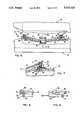
- FIG. 3is a top plan view of the swivel ring shown in FIG. 1.
- FIG. 4is a partial top plan view of the apparatus showing the base, bottom portion of the monitor and the swivel ring in place in the groove located in the base.
- FIG. 5is an enlarged sectional view of the swivel ring locking mechanism showing it in the unlocked position.
- FIG. 6is a partial, cross-sectional view of the apparatus taken along line 6--6 of FIG. 4.
- FIG. 7is an enlarged, segmented view of the access opening for the unlocking of the swivel ring.
- FIG. 8is a detailed, cross-sectional, segmented view of the swivel ring taken along line 8--8 of FIG. 3, showing a lug.
- FIG. 9is a detailed, cross-sectional, segmented view of the swivel ring taken along line 9--9 of FIG. 3.
- FIG. 10is a partial, cross-sectional view of the key and lock arrangement taken along line 10--10 of FIG. 6.
- FIG. 11is a partial bottom plan view of the display monitor illustrating an alternative implementation of the spherical surface extending from its bottom portion.
- FIG. 12is a partial, cross-sectional view of the embodiment taken along line 12--12 of FIG. 11.
- FIG. 1there is shown an exploded, perspective view of a video display terminal 10 having a display monitor, generally designated by reference numeral 20, and a base, generally designated by reference numeral 30.
- the base 30serves as a stand for the display monitor 20 and houses the terminal's electronics (not shown). Enclosures for the monitor 20 and the base 30 may be molded from plastic material.
- Apparatus for mounting the monitor 20 on base 30 and permitting and limiting the extent of tilting and swiveling of the monitor 20includes a convex, generally spherical surface 21 extending from the bottom of the monitor 20.
- the surface 21serves as a ball for mating with a socket 31, which is formed in the base 30.
- Collar 32has a two step groove 33 which includes an upper flat surface 34 and a lower flat surface 35. A cross-sectional view of the groove 33 is shown in FIG. 7.
- the groove 33is arranged to accommodate a friction ring 60, which may be molded from a plastic material.
- the friction ring 60has a substantially rectangular cross-sectional area, as shown in FIG. 7, and is located in groove 33 on the flat surface 34. The function of the friction ring 60 will be discussed later on.
- Groove 33is further arranged to accommodate a swivel ring 50, a top view of which is shown in FIG. 3.
- the swivel ring 50may be molded from a polycarbonate material and is made up of a top portion 51 and a bottom portion 52, as best shown in a cross-sectional view in FIG. 8.
- Portion 51has a flat bottom surface 53, which seats on top of the friction ring 60 and portion 52 has a flat bottom surface 54 which clears the flat surface 35 of groove 33.
- the swivel ring 50may slide on the friction ring 60, or the friction ring 60 may slide on its seat--surface 34 of groove 33.
- Friction ring 60allows an easy and convenient way to change the swivel friction by inserting rings with different frictional properties.
- the top surface 55 of portion 51 of the swivel ringis beveled and approximates the spherically contoured surface 21 of monitor 20, when the monitor is placed on top of the base 30.
- Extending or projecting upwardly from the swivel ring 50are two projections 56 for engaging slots 22 of the spherical surface 21. The function of slots 22 and projections 56 will be disussed later on.
- swivel ring 50has a flexible section 57, which is shown in FIG. 3.
- the flexible section 57is constructed by separating the two portions 51 and 52 of the ring 50 by removing material joining the two portions 51 and 52, as shown in FIG. 9.
- a projection 59extends from the flexible section 57 radially outward. The projection 59 is used to limit the extent of rotation of the swivel ring 50 in groove 33, and thus the extent of swivel of the monitor.
- a section of the swivel ring groove 33is arranged to accommodate the projection 59.
- two portions of the groove 33 associated with surface 34are recessed, creating swivel stops 36 through 38.
- the projection 59moves in the recess between stops 36 and 37, which determine the extent of left and right swivel, respectively.
- the monitor 20can be removed from the base 30.
- FIG. 4shows the swivel ring 50 located in the groove 33, with projection 59 against stop 37.
- a force Fis applied, as shown in FIGS. 5 and 7, with a slender rod or the like through an opening 39 in the collar 32 to the flexible section 57 to move the flexible section 57 away from swivel stop 37.
- the swivel ring 50can then be rotated counter clockwise until projection 59 encounters stop 38.
- a portion of groove 33 associated with surface 35 and located generally opposite the opening 39 and stop 37is enlarged.
- T-shaped keyExtending upwardly from the center of socket 31 and integral therewith is a T-shaped key made up of leg 42 and a foot 43. A cross-sectional view of the key is shown in FIG. 10.
- the foot 43is oriented so it is substantially parallel to the X axis of the base 30 as illustrated in FIGS. 2, 3, and 4 of the drawing.
- the T-shaped keyis arranged for communicating with a lock slot 23 located in the bottom of the spherical surface 21, as shown in FIG. 11.
- Lock slot 23is oriented substantially parallel to the Z axis of the monitor 20.
- the width of the lock slot 23is slightly larger than that the width of the foot 43, such that the foot 43 can enter the slot 23 when the two are aligned.
- Lock slot 23permits foot 43 to freely slide within the length of the slot wherein the length of the slot 23 limits the extent of tilt angle of the monitor 20.
- FIG. 1For an understanding of the apparatus relative to the mounting and dismounting of monitor 20 on base 30, reference is made to FIG. 1.
- the friction ring 60 and the swivel ring 50are placed in groove 33, with the projection 59 of the swivel ring 50 against stop 38.
- the monitor 20is placed over base 30, with the spherical surface 21 lining up with socket 31, and the monitor 20 rotated 90 degrees counter clockwise from X axis of the base 30.
- These actionsline up foot 43 with lock slot 23 and projections 56 of the swivel ring 50 with respective slots 22 in the spherical surface 21.
- the monitor 20may then be lowered on top of base 30 such that spherical surface 21 enters the cavity formed of spherical surface 31, foot 43 enters and passes through slot 23 and projections 56 enter their respective slots 22. As shown in FIG. 7, the spherical surface 21 is engaged by the bevel surface 55, leaving a clearance between the spherical surface 21 and the socket 31. The monitor 20 is then rotated clockwise, and since projections 56 are engaged by slots 22, the swivel ring 50 rotates with the monitor 20.
- Removal of the monitor 20 from the base 30is accomplished by rotating the monitor 20 counterclockwise until projection 59 comes up against the stop 37; unlocking the swivel ring 50 in a manner disclosed previously utilizing the access opening 39 located in the collar 32; and continuing with the counterclockwise rotation until projection 59 encounters the stop 38 at which point foot 43 is aligned with the lock slot 23 allowing the monitor 20 to be lifted off the base 30.
- the spherical surface 21 of monitor 20includes raised, spherically contoured areas 24 and 25 for mating with the beveled surface 55 of the swivel ring 50.
- the raised areas 24 and 25provide a basically three point support to the monitor 20 and reduce or eliminate any instability between the monitor 20 and the base 30 which may be caused by imperfections in the spherical surface 21 and the beveled surface 55.
- the spherical surface 21having a diameter of approximately 12.5 inches, it was determined experimentally that to ensure sufficient wear areas, the width of each raised area 24 was to be approximately 0.3 inch and the width of each raised area 25 approximately 0.5 inch. It was also determined experimentally that textured surfaces on the raised areas 24 and 25 ensured a smoother tilting action and substantially eliminated lock-up between the mating surfaces.
Landscapes
- Engineering & Computer Science (AREA)
- General Engineering & Computer Science (AREA)
- Mechanical Engineering (AREA)
- Devices For Indicating Variable Information By Combining Individual Elements (AREA)
Abstract
Description
Claims (11)
Priority Applications (1)
| Application Number | Priority Date | Filing Date | Title |
|---|---|---|---|
| US07/429,239US5024415A (en) | 1989-10-30 | 1989-10-30 | Tilt and swivel apparatus for a display monitor |
Applications Claiming Priority (1)
| Application Number | Priority Date | Filing Date | Title |
|---|---|---|---|
| US07/429,239US5024415A (en) | 1989-10-30 | 1989-10-30 | Tilt and swivel apparatus for a display monitor |
Publications (1)
| Publication Number | Publication Date |
|---|---|
| US5024415Atrue US5024415A (en) | 1991-06-18 |
Family
ID=23702400
Family Applications (1)
| Application Number | Title | Priority Date | Filing Date |
|---|---|---|---|
| US07/429,239Expired - Fee RelatedUS5024415A (en) | 1989-10-30 | 1989-10-30 | Tilt and swivel apparatus for a display monitor |
Country Status (1)
| Country | Link |
|---|---|
| US (1) | US5024415A (en) |
Cited By (40)
| Publication number | Priority date | Publication date | Assignee | Title |
|---|---|---|---|---|
| WO1992003293A1 (en) | 1990-08-23 | 1992-03-05 | David Hegarty | Universal document support stand |
| US5209446A (en)* | 1991-02-18 | 1993-05-11 | Mitsubishi Denki Kabushiki Kaisha | Rotary stand |
| US5243434A (en)* | 1990-06-29 | 1993-09-07 | Mitsubishi Denki Kabushiki Kaisha | Swivel device for a television receiver |
| US5404182A (en)* | 1993-10-28 | 1995-04-04 | Nippon Control Industrial Co., Ltd. | Swivel chassis |
| USD363276S (en) | 1992-11-13 | 1995-10-17 | International Business Machines Corporation | Docking base for a portable computer |
| US5465936A (en)* | 1994-08-16 | 1995-11-14 | Wang; Tsong L. | Rotatable bracket of a monitor |
| US5470041A (en)* | 1994-02-02 | 1995-11-28 | Cucinotta; James L. | Workstation for laptop-type computer |
| US5529265A (en)* | 1993-06-30 | 1996-06-25 | Sony Corporation | Disc signal display system for use with plural seats |
| US5632463A (en)* | 1994-06-13 | 1997-05-27 | Samsung Electronics Co., Ltd. | Monitor stand assembly |
| US5708561A (en)* | 1996-08-13 | 1998-01-13 | Vivek R. Huilgol | Portable computer having display slidably and rotatably mounted for movement between landscape and portrait orientation and to open and close speaker ports |
| US5755420A (en)* | 1996-07-16 | 1998-05-26 | Mag Technology Co., Ltd. | Swivel base structure |
| US5971268A (en)* | 1993-05-27 | 1999-10-26 | International Business Machines Corporation | I/O assembly for use with point of sale terminals and other computing systems |
| US6007038A (en)* | 1997-12-27 | 1999-12-28 | Daewoo Electronics Co., Ltd. | Tilt and swivel apparatus for a display monitor |
| US6010111A (en)* | 1996-11-15 | 2000-01-04 | Samsung Electronics Co., Ltd. | Swiveling device for liquid crystal display monitor |
| US6089520A (en)* | 1996-09-03 | 2000-07-18 | Mag Technology Co., Ltd. | Swivel base structure |
| US6105919A (en)* | 1997-05-27 | 2000-08-22 | Samsung Electronics Co., Ltd. | Liquid crystal display with wide swivel angle |
| US6510049B2 (en)* | 2000-01-06 | 2003-01-21 | Rosen Products Llc | Adjustable display monitor unit |
| US6522529B1 (en) | 2000-05-22 | 2003-02-18 | Vivek R. Huilgol | Rotatable computer display apparatus and method |
| US20030132360A1 (en)* | 2002-01-11 | 2003-07-17 | Ju Li Ta | Structure of an adjustable LCD screen |
| US20030184193A1 (en)* | 2002-03-26 | 2003-10-02 | Samsung Electronics Co., Ltd. | Monitor having improved swiveling |
| US20030199378A1 (en)* | 2002-04-19 | 2003-10-23 | Kendro Laboratory Products, Inc. | Centrifuge sleep mode control |
| US6644616B1 (en)* | 1999-12-14 | 2003-11-11 | Fujitsu Limited | Tilt swivel stand |
| US6801426B2 (en)* | 2001-04-16 | 2004-10-05 | Fujitsu Limited | Display device with pivotable base |
| US20050189540A1 (en)* | 2004-03-01 | 2005-09-01 | Bae Systems, Information And Electronic Systems Integration Inc. | Module inspection fixture |
| US20060007644A1 (en)* | 2004-07-08 | 2006-01-12 | Huilgol Vivek R | Rotatable computer display apparatus and method |
| CN101539236B (en)* | 2009-04-09 | 2011-03-30 | 南京Lg新港显示有限公司 | Flat-panel display base |
| US20160357999A1 (en)* | 2015-06-03 | 2016-12-08 | Wistron Corp. | Rotatable assembly and scanning device including the same |
| US9829148B2 (en) | 2015-10-03 | 2017-11-28 | Samuel Choquette | Rotatable platter for a monitor having a passage for wiring and a stopper |
| WO2019241867A1 (en)* | 2018-06-22 | 2019-12-26 | Tolife Tecnologia Para A Saúde S.A. | Apparatus for triage in health facilities |
| WO2021091547A1 (en)* | 2019-11-06 | 2021-05-14 | Hewlett-Packard Development Company, L.P. | Computing device stands and display mount interface spacers |
| CN113374994A (en)* | 2021-05-11 | 2021-09-10 | 金陵科技学院 | Interactive image projection equipment and use method thereof |
| US11274787B2 (en)* | 2019-05-30 | 2022-03-15 | Alcon Inc. | Stopping element for limiting rotational range of a rotating part |
| USD969113S1 (en)* | 2020-03-27 | 2022-11-08 | Music Express, Llc | Speaker bracket |
| JP2022184041A (en)* | 2021-05-31 | 2022-12-13 | 株式会社kiwami | Display device and method for adjusting display position of aerial image by display device |
| USD975068S1 (en)* | 2020-03-27 | 2023-01-10 | Music Express, Llc | Dual-axis swivel speaker mount assembly |
| USD1026872S1 (en) | 2022-05-19 | 2024-05-14 | Music Express Llc | Dual-axis swivel speaker mount |
| USD1026871S1 (en) | 2022-05-19 | 2024-05-14 | Music Express Llc | Dual-axis swivel speaker mount |
| US11997452B2 (en) | 2022-05-19 | 2024-05-28 | Music Express Llc | Dual-axis swivel speaker mount assembly and mounting kit |
| USD1030451S1 (en) | 2022-05-19 | 2024-06-11 | Music Express Llc | Speaker mounting plate |
| USD1034545S1 (en) | 2022-05-19 | 2024-07-09 | Music Express Llc | Speaker mounting plate |
Citations (14)
| Publication number | Priority date | Publication date | Assignee | Title |
|---|---|---|---|---|
| US4304385A (en)* | 1980-01-17 | 1981-12-08 | Icl, Inc. | Tilt, swivel and vertical control mechanism for CRT terminal |
| US4365779A (en)* | 1980-06-16 | 1982-12-28 | International Business Machines Corp. | Tilt and rotate apparatus for a display monitor |
| US4471931A (en)* | 1983-03-18 | 1984-09-18 | Teletype Corporation | CRT Monitor tilt mechanism |
| US4473206A (en)* | 1981-10-09 | 1984-09-25 | Convergent Technologies, Inc. | Articulated structure for supporting loads |
| US4494720A (en)* | 1981-12-14 | 1985-01-22 | Digital Equipment Corporation | Tilt swivel base |
| US4554590A (en)* | 1980-06-05 | 1985-11-19 | Ing. C. Olivetti & C., S.P.A. | Device for positioning video display unit |
| US4564166A (en)* | 1983-01-21 | 1986-01-14 | Delta Data Systems Corporation | Rotary tilt base for video terminal |
| US4570892A (en)* | 1984-12-11 | 1986-02-18 | Zenith Electronics Corporation | Tiltable rotating display monitor mount |
| US4589713A (en)* | 1984-04-09 | 1986-05-20 | Raytheon Company | Video display support joint |
| US4591120A (en)* | 1981-07-20 | 1986-05-27 | International Business Machines Corporation | Tiltable and/or rotatable support for display device |
| US4621782A (en)* | 1984-07-26 | 1986-11-11 | At&T Bell Laboratories | Arrangement for mounting apparatus |
| US4645153A (en)* | 1985-05-23 | 1987-02-24 | Ncr Corporation | Tilt and swivel support |
| US4738422A (en)* | 1986-11-10 | 1988-04-19 | Hewlett-Packard Company | Adjustable tilt/swivel/cable dress |
| US4852830A (en)* | 1988-07-21 | 1989-08-01 | Apple Computer, Inc. | Computer moniter stand |
- 1989
- 1989-10-30USUS07/429,239patent/US5024415A/ennot_activeExpired - Fee Related
Patent Citations (14)
| Publication number | Priority date | Publication date | Assignee | Title |
|---|---|---|---|---|
| US4304385A (en)* | 1980-01-17 | 1981-12-08 | Icl, Inc. | Tilt, swivel and vertical control mechanism for CRT terminal |
| US4554590A (en)* | 1980-06-05 | 1985-11-19 | Ing. C. Olivetti & C., S.P.A. | Device for positioning video display unit |
| US4365779A (en)* | 1980-06-16 | 1982-12-28 | International Business Machines Corp. | Tilt and rotate apparatus for a display monitor |
| US4591120A (en)* | 1981-07-20 | 1986-05-27 | International Business Machines Corporation | Tiltable and/or rotatable support for display device |
| US4473206A (en)* | 1981-10-09 | 1984-09-25 | Convergent Technologies, Inc. | Articulated structure for supporting loads |
| US4494720A (en)* | 1981-12-14 | 1985-01-22 | Digital Equipment Corporation | Tilt swivel base |
| US4564166A (en)* | 1983-01-21 | 1986-01-14 | Delta Data Systems Corporation | Rotary tilt base for video terminal |
| US4471931A (en)* | 1983-03-18 | 1984-09-18 | Teletype Corporation | CRT Monitor tilt mechanism |
| US4589713A (en)* | 1984-04-09 | 1986-05-20 | Raytheon Company | Video display support joint |
| US4621782A (en)* | 1984-07-26 | 1986-11-11 | At&T Bell Laboratories | Arrangement for mounting apparatus |
| US4570892A (en)* | 1984-12-11 | 1986-02-18 | Zenith Electronics Corporation | Tiltable rotating display monitor mount |
| US4645153A (en)* | 1985-05-23 | 1987-02-24 | Ncr Corporation | Tilt and swivel support |
| US4738422A (en)* | 1986-11-10 | 1988-04-19 | Hewlett-Packard Company | Adjustable tilt/swivel/cable dress |
| US4852830A (en)* | 1988-07-21 | 1989-08-01 | Apple Computer, Inc. | Computer moniter stand |
Cited By (50)
| Publication number | Priority date | Publication date | Assignee | Title |
|---|---|---|---|---|
| US5243434A (en)* | 1990-06-29 | 1993-09-07 | Mitsubishi Denki Kabushiki Kaisha | Swivel device for a television receiver |
| WO1992003293A1 (en) | 1990-08-23 | 1992-03-05 | David Hegarty | Universal document support stand |
| US5209446A (en)* | 1991-02-18 | 1993-05-11 | Mitsubishi Denki Kabushiki Kaisha | Rotary stand |
| USD363276S (en) | 1992-11-13 | 1995-10-17 | International Business Machines Corporation | Docking base for a portable computer |
| US5971268A (en)* | 1993-05-27 | 1999-10-26 | International Business Machines Corporation | I/O assembly for use with point of sale terminals and other computing systems |
| US5529265A (en)* | 1993-06-30 | 1996-06-25 | Sony Corporation | Disc signal display system for use with plural seats |
| US5404182A (en)* | 1993-10-28 | 1995-04-04 | Nippon Control Industrial Co., Ltd. | Swivel chassis |
| US5470041A (en)* | 1994-02-02 | 1995-11-28 | Cucinotta; James L. | Workstation for laptop-type computer |
| US5632463A (en)* | 1994-06-13 | 1997-05-27 | Samsung Electronics Co., Ltd. | Monitor stand assembly |
| US5465936A (en)* | 1994-08-16 | 1995-11-14 | Wang; Tsong L. | Rotatable bracket of a monitor |
| US5755420A (en)* | 1996-07-16 | 1998-05-26 | Mag Technology Co., Ltd. | Swivel base structure |
| US5708561A (en)* | 1996-08-13 | 1998-01-13 | Vivek R. Huilgol | Portable computer having display slidably and rotatably mounted for movement between landscape and portrait orientation and to open and close speaker ports |
| US6089520A (en)* | 1996-09-03 | 2000-07-18 | Mag Technology Co., Ltd. | Swivel base structure |
| US6010111A (en)* | 1996-11-15 | 2000-01-04 | Samsung Electronics Co., Ltd. | Swiveling device for liquid crystal display monitor |
| US6105919A (en)* | 1997-05-27 | 2000-08-22 | Samsung Electronics Co., Ltd. | Liquid crystal display with wide swivel angle |
| US6007038A (en)* | 1997-12-27 | 1999-12-28 | Daewoo Electronics Co., Ltd. | Tilt and swivel apparatus for a display monitor |
| US6644616B1 (en)* | 1999-12-14 | 2003-11-11 | Fujitsu Limited | Tilt swivel stand |
| US6869056B2 (en) | 1999-12-14 | 2005-03-22 | Fujitsu Limited | Tilt-swivel stand |
| US20040051012A1 (en)* | 1999-12-14 | 2004-03-18 | Fujitsu Limited | Tilt-swivel stand |
| US6510049B2 (en)* | 2000-01-06 | 2003-01-21 | Rosen Products Llc | Adjustable display monitor unit |
| US6522529B1 (en) | 2000-05-22 | 2003-02-18 | Vivek R. Huilgol | Rotatable computer display apparatus and method |
| US6801426B2 (en)* | 2001-04-16 | 2004-10-05 | Fujitsu Limited | Display device with pivotable base |
| US7303174B2 (en)* | 2002-01-11 | 2007-12-04 | Ta Ju Li | Structure of an adjustable LCD screen |
| US20030132360A1 (en)* | 2002-01-11 | 2003-07-17 | Ju Li Ta | Structure of an adjustable LCD screen |
| US20030184193A1 (en)* | 2002-03-26 | 2003-10-02 | Samsung Electronics Co., Ltd. | Monitor having improved swiveling |
| US20030199378A1 (en)* | 2002-04-19 | 2003-10-23 | Kendro Laboratory Products, Inc. | Centrifuge sleep mode control |
| US7407473B2 (en)* | 2002-04-19 | 2008-08-05 | Thermo Fisher Scientific (Asheville) Llc | Centrifuge sleep mode control |
| US7268941B2 (en)* | 2004-03-01 | 2007-09-11 | Bae Systems Information And Electronic Systems Integration Inc. | Module inspection fixture |
| US20050189540A1 (en)* | 2004-03-01 | 2005-09-01 | Bae Systems, Information And Electronic Systems Integration Inc. | Module inspection fixture |
| US7082028B2 (en) | 2004-07-08 | 2006-07-25 | Swivel It, Inc. | Rotatable computer display apparatus and method |
| US20060007644A1 (en)* | 2004-07-08 | 2006-01-12 | Huilgol Vivek R | Rotatable computer display apparatus and method |
| CN101539236B (en)* | 2009-04-09 | 2011-03-30 | 南京Lg新港显示有限公司 | Flat-panel display base |
| US20160357999A1 (en)* | 2015-06-03 | 2016-12-08 | Wistron Corp. | Rotatable assembly and scanning device including the same |
| US10032054B2 (en)* | 2015-06-03 | 2018-07-24 | Wistron Corp. | Rotatable assembly and scanning device including the same |
| US9829148B2 (en) | 2015-10-03 | 2017-11-28 | Samuel Choquette | Rotatable platter for a monitor having a passage for wiring and a stopper |
| WO2019241867A1 (en)* | 2018-06-22 | 2019-12-26 | Tolife Tecnologia Para A Saúde S.A. | Apparatus for triage in health facilities |
| US11274787B2 (en)* | 2019-05-30 | 2022-03-15 | Alcon Inc. | Stopping element for limiting rotational range of a rotating part |
| WO2021091547A1 (en)* | 2019-11-06 | 2021-05-14 | Hewlett-Packard Development Company, L.P. | Computing device stands and display mount interface spacers |
| USD969113S1 (en)* | 2020-03-27 | 2022-11-08 | Music Express, Llc | Speaker bracket |
| USD975068S1 (en)* | 2020-03-27 | 2023-01-10 | Music Express, Llc | Dual-axis swivel speaker mount assembly |
| US12185042B2 (en) | 2020-03-27 | 2024-12-31 | Music Express Llc | Dual-axis swivel speaker mount assembly |
| CN113374994A (en)* | 2021-05-11 | 2021-09-10 | 金陵科技学院 | Interactive image projection equipment and use method thereof |
| CN113374994B (en)* | 2021-05-11 | 2023-08-25 | 金陵科技学院 | A device for interactive image projection and its use method |
| JP2022184041A (en)* | 2021-05-31 | 2022-12-13 | 株式会社kiwami | Display device and method for adjusting display position of aerial image by display device |
| JP7623690B2 (en) | 2021-05-31 | 2025-01-29 | 株式会社kiwami | Display device and method for adjusting display position of aerial image by display device |
| USD1026872S1 (en) | 2022-05-19 | 2024-05-14 | Music Express Llc | Dual-axis swivel speaker mount |
| USD1026871S1 (en) | 2022-05-19 | 2024-05-14 | Music Express Llc | Dual-axis swivel speaker mount |
| US11997452B2 (en) | 2022-05-19 | 2024-05-28 | Music Express Llc | Dual-axis swivel speaker mount assembly and mounting kit |
| USD1030451S1 (en) | 2022-05-19 | 2024-06-11 | Music Express Llc | Speaker mounting plate |
| USD1034545S1 (en) | 2022-05-19 | 2024-07-09 | Music Express Llc | Speaker mounting plate |
Similar Documents
| Publication | Publication Date | Title |
|---|---|---|
| US5024415A (en) | Tilt and swivel apparatus for a display monitor | |
| US5588625A (en) | Monitor stand assembly | |
| EP0221132B1 (en) | Tilt and rotate apparatus for supporting a structure | |
| CA1169648A (en) | Tilt and rotate apparatus for a display monitor | |
| EP0070337B1 (en) | A tiltable and/or rotatable support for a display device | |
| EP0070336B1 (en) | A tiltable and/or rotatable support for a display device | |
| US5398903A (en) | Video display mounting device | |
| EP0260728A2 (en) | Container-classifier for flat objects, in particular for computer disks | |
| JPH081407U (en) | Interlock assembly for adjustable mounting of display unit | |
| US7665185B2 (en) | Incremental locking hinge assembly | |
| EP0877570A1 (en) | Tree stand | |
| US4769634A (en) | Tilt apparatus for cathode ray tube display | |
| EP0160237B1 (en) | Tiltable cathode ray tube display device structure | |
| US6318694B1 (en) | Support device for supporting electronic device obliquely and pivotally | |
| CA1225979A (en) | Adjustable height support device for a video display unit or the like | |
| US6921173B2 (en) | Tilt-foot mechanism for projector | |
| JP6997688B2 (en) | Swivel mechanism and display device | |
| KR0139548Y1 (en) | Tilt or swivel apparatus for lcd monitor | |
| JP3365090B2 (en) | Tilt swivel lock mechanism for display device | |
| JP2866062B2 (en) | caster | |
| JPS6130536Y2 (en) | ||
| JPH073971Y2 (en) | Product display shelf display device | |
| KR100389719B1 (en) | Sustaining structure for adjusting slope of projector | |
| KR850001542Y1 (en) | Crt terminal | |
| KR200189954Y1 (en) | Monitor stand |
Legal Events
| Date | Code | Title | Description |
|---|---|---|---|
| AS | Assignment | Owner name:AT&T-IS, AMERICAN TELEPHONE AND TELEGRAPH COMPANY, Free format text:ASSIGNMENT OF ASSIGNORS INTEREST.;ASSIGNOR:PURENS, ALFRED;REEL/FRAME:005170/0100 Effective date:19891027 Owner name:AT&T INFORMATION SYSTEMS INC., NEW JERSEY Free format text:ASSIGNMENT OF ASSIGNORS INTEREST.;ASSIGNOR:PURENS, ALFRED;REEL/FRAME:005170/0100 Effective date:19891027 | |
| FEPP | Fee payment procedure | Free format text:PAYOR NUMBER ASSIGNED (ORIGINAL EVENT CODE: ASPN); ENTITY STATUS OF PATENT OWNER: LARGE ENTITY | |
| FPAY | Fee payment | Year of fee payment:4 | |
| FEPP | Fee payment procedure | Free format text:PAYER NUMBER DE-ASSIGNED (ORIGINAL EVENT CODE: RMPN); ENTITY STATUS OF PATENT OWNER: LARGE ENTITY Free format text:PAYOR NUMBER ASSIGNED (ORIGINAL EVENT CODE: ASPN); ENTITY STATUS OF PATENT OWNER: LARGE ENTITY | |
| FEPP | Fee payment procedure | Free format text:PAYER NUMBER DE-ASSIGNED (ORIGINAL EVENT CODE: RMPN); ENTITY STATUS OF PATENT OWNER: LARGE ENTITY Free format text:PAYOR NUMBER ASSIGNED (ORIGINAL EVENT CODE: ASPN); ENTITY STATUS OF PATENT OWNER: LARGE ENTITY | |
| FPAY | Fee payment | Year of fee payment:8 | |
| REMI | Maintenance fee reminder mailed | ||
| LAPS | Lapse for failure to pay maintenance fees | ||
| STCH | Information on status: patent discontinuation | Free format text:PATENT EXPIRED DUE TO NONPAYMENT OF MAINTENANCE FEES UNDER 37 CFR 1.362 | |
| FP | Lapsed due to failure to pay maintenance fee | Effective date:20030618 |