US5024160A - Rapid burning propellant charge for automobile air bag inflators, rocket motors, and igniters therefor - Google Patents
Rapid burning propellant charge for automobile air bag inflators, rocket motors, and igniters thereforDownload PDFInfo
- Publication number
- US5024160A US5024160AUS07/158,829US15882988AUS5024160AUS 5024160 AUS5024160 AUS 5024160AUS 15882988 AUS15882988 AUS 15882988AUS 5024160 AUS5024160 AUS 5024160A
- Authority
- US
- United States
- Prior art keywords
- propellant
- gas generant
- ligaments
- gas
- charge
- Prior art date
- Legal status (The legal status is an assumption and is not a legal conclusion. Google has not performed a legal analysis and makes no representation as to the accuracy of the status listed.)
- Expired - Fee Related
Links
Images


Classifications
- B—PERFORMING OPERATIONS; TRANSPORTING
- B60—VEHICLES IN GENERAL
- B60R—VEHICLES, VEHICLE FITTINGS, OR VEHICLE PARTS, NOT OTHERWISE PROVIDED FOR
- B60R21/00—Arrangements or fittings on vehicles for protecting or preventing injuries to occupants or pedestrians in case of accidents or other traffic risks
- B60R21/02—Occupant safety arrangements or fittings, e.g. crash pads
- B60R21/16—Inflatable occupant restraints or confinements designed to inflate upon impact or impending impact, e.g. air bags
- B60R21/26—Inflatable occupant restraints or confinements designed to inflate upon impact or impending impact, e.g. air bags characterised by the inflation fluid source or means to control inflation fluid flow
- B60R21/264—Inflatable occupant restraints or confinements designed to inflate upon impact or impending impact, e.g. air bags characterised by the inflation fluid source or means to control inflation fluid flow using instantaneous generation of gas, e.g. pyrotechnic
- B60R21/2644—Inflatable occupant restraints or confinements designed to inflate upon impact or impending impact, e.g. air bags characterised by the inflation fluid source or means to control inflation fluid flow using instantaneous generation of gas, e.g. pyrotechnic using only solid reacting substances, e.g. pellets, powder
- C—CHEMISTRY; METALLURGY
- C06—EXPLOSIVES; MATCHES
- C06B—EXPLOSIVES OR THERMIC COMPOSITIONS; MANUFACTURE THEREOF; USE OF SINGLE SUBSTANCES AS EXPLOSIVES
- C06B21/00—Apparatus or methods for working-up explosives, e.g. forming, cutting, drying
- C06B21/0083—Treatment of solid structures, e.g. for coating or impregnating with a modifier
- C—CHEMISTRY; METALLURGY
- C06—EXPLOSIVES; MATCHES
- C06B—EXPLOSIVES OR THERMIC COMPOSITIONS; MANUFACTURE THEREOF; USE OF SINGLE SUBSTANCES AS EXPLOSIVES
- C06B45/00—Compositions or products which are defined by structure or arrangement of component of product
- C—CHEMISTRY; METALLURGY
- C06—EXPLOSIVES; MATCHES
- C06D—MEANS FOR GENERATING SMOKE OR MIST; GAS-ATTACK COMPOSITIONS; GENERATION OF GAS FOR BLASTING OR PROPULSION (CHEMICAL PART)
- C06D5/00—Generation of pressure gas, e.g. for blasting cartridges, starting cartridges, rockets
- F—MECHANICAL ENGINEERING; LIGHTING; HEATING; WEAPONS; BLASTING
- F42—AMMUNITION; BLASTING
- F42B—EXPLOSIVE CHARGES, e.g. FOR BLASTING, FIREWORKS, AMMUNITION
- F42B3/00—Blasting cartridges, i.e. case and explosive
- F42B3/04—Blasting cartridges, i.e. case and explosive for producing gas under pressure
- F—MECHANICAL ENGINEERING; LIGHTING; HEATING; WEAPONS; BLASTING
- F42—AMMUNITION; BLASTING
- F42B—EXPLOSIVE CHARGES, e.g. FOR BLASTING, FIREWORKS, AMMUNITION
- F42B5/00—Cartridge ammunition, e.g. separately-loaded propellant charges
- F42B5/02—Cartridges, i.e. cases with charge and missile
- F42B5/16—Cartridges, i.e. cases with charge and missile characterised by composition or physical dimensions or form of propellant charge, with or without projectile, or powder
Definitions
- the present inventionrelates to solid propellant charges.
- Uses of the propellant charges of the present inventioninclude, but are not limited to, igniters and launch eject motors where it is desired that the propellant charges burn rapidly for rapid development of heat or thrust.
- Other uses of the propellant charges of the present inventionare as gas generators for automobile air bag inflators as well as other apparatus where it is desired to produce inflating gas rapidly. Therefore, for the purposes of this specification and the claims, a "propellant charge” is meant to include gas generators for air bag inflation systems and other inflation systems.
- this inventionis not limited to just these uses, but may find uses, for example, as main propulsion propellant charges for rocket motors.
- a typical solid propellant chargeincludes a fuel such as aluminum particles and an oxidizer such as ammonium perchlorate which are usually bound together by a binder such as hydroxy terminated polybutadiene.
- the bindermay also act as a fuel.
- the fuel and oxidizerare separate materials which are mixed together to form the propellant, the propellant is known as a "composite propellant.”
- a composite propellantis usually manufactured by blending the ingredients into a thick and viscous but still pourable mixture which is then added to the rocket motor chamber where the mixture is cast and cured into a solid mass of propellant material in position for use.
- the propellant mixturemay be extruded into a desired geometric shape such as, for example, pellets for an air bag inflator, as illustrated at 62 in U.S. Pat. No. 4,547,342 to Adams et al.
- burningproceeds in a direction perpendicular to the surface at all times.
- a type of rocket motorknown as an end burner wherein the propellant grain is a solid mass of propellant without a perforation therein
- burningis initiated at the nozzle end and proceeds in a direction toward the head end of the rocket.
- the burning time for an end burner type of propellant grainis relatively slow compared to those propellant grains which are perforated longitudinally usually along their longitudinal center lines. In this type of grain, burning may be initiated along the entire length of the propellant grain so that the burning proceeds from the perforation radially outwardly toward the rocket motor case.
- the burning time for a propellant chargeis also determined by the shape of the internal perforation, the shape known as a "tube shape” or “center perforate” being relatively slower burning, for example, than the shape known as the "internal star shape" of propellant grain.
- Tactical weaponssuch as canister fired missiles may use launch eject motors containing solid propellant charges for ejecting missiles out of their canisters before their main motors ignite. It is desirable that the propellant grain for the launch eject motor as well as the propellant charge for the igniter for the flight motor thereof be of the smokeless or minimum smoke type since large quantities of smoke or exhaust including any toxic gas therein may be injurious to the operators thereof, and the smoke or exhaust may undesirably hinder visibility of the target which visibility must be maintained after launch for control of the missile. However, smokeless or minimum smoke propellants do not usually burn as fast as is normally desired.
- this type of propellanttends to become soft in the high temperatures typically encountered or which may be encountered in areas of the world where such tactical weapons may be used. If the propellant becomes too soft and its physical state is as a result altered such as during acceleration as the missile is ejected from the canister, the burning properties of the propellant are accordingly altered resulting possibly in an inadequate burning rate or possible explosion of the launch eject motor.
- U.S. Pat. No. 4,321,220 to Campdiscloses a method for strengthening a propellant charge by incorporating a support structure in the propellant charge. The method is disclosed as comprising slowly traversing a flexible perforated material through a propellant lacquer until the desired loading is obtained. Camp states that the "reinforcing" substrate is perforated or the like so that it is “permeable to propellant decomposition gases which evolve during storage" and should also be strong and have a low density.
- Campstates that the "reinforced" propellant should have a “waffle appearance” so as to have “desirably increased surface area”
- the disclosure in Campaddresses the problems of increasing propellant strength, and the "waffle appearance", while a step in the right direction, still does not provide a sufficiently rapid burning smokeless or minimum smoke propellant charge.
- the Walz patentsdo not disclose increasing propellant charge surface area to achieve more rapid burning thereof and do not therefore afford an adequate solution to the problem either.
- "Burn time”refers to the time it takes to burn a specified volume of a propellant charge and varies depending on the physical configuration of the propellant charge as well as the type of propellant.
- "burn rate" perpendicular to the surface of a propellantis constant for a particular propellant material.
- Igniter propellant materialwhich consists of pellets of boron and potassium nitrate must be placed in a housing such as a wire basket or tube which is perforated so that the propellant gases from the igniter may communicate with a propellant grain for ignition thereof.
- a housingsuch as a wire basket or tube which is perforated so that the propellant gases from the igniter may communicate with a propellant grain for ignition thereof.
- wire baskets or perforated tubesmay get blown off during the ignition phase or get plugged up both of which conditions affect the safety of the rocket. It is a further object of the present invention to eliminate such a basket or tube for an igniter and thus also reduce the expense thereof.
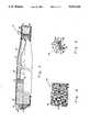
- FIG. 1is a side view of a canister fired missile embodying the present invention with a portion of the case broken away;
- FIG. 2is a half cross-sectional view, taken in a longitudinal plane, providing a detailed view of the broken away portion of FIG. 1;
- FIG. 3is a partially cross-sectional view, taken in a longitudinal plane, of the flight motor of FIG. 1;
- FIG. 4is a perspective view of a portion of a reticulated structure for a solid propellant charge embodying the present invention
- FIG. 5is a sectional enlarged view of a portion of a solid propellant charge embodying the present invention, including a portion of the reticulated structure of FIG. 4;
- FIG. 6is a cross-sectional view of a gas bag inflator embodying the present invention.
- a canister fired missile at 10which may be shoulder launched and which includes a launch eject motor 12 and a flight motor 14.
- the launch motor 12is a solid propellant motor which is used to eject the flight motor 14, which has a length typically of from about 10 inches to about 6 feet, out of a canister (not shown) afterwhich the flight motor 14 is caused to ignite when it is a safe distance away from the operator.
- the size of the launch motor 12is related to the flight motor size. For a flight motor having a length of 40 inches, the launch motor may have a length of about 4 inches.
- the launch motor 12includes a generally cylindrical case 16 and nozzle 18.
- an electric match or initiatorcommonly know as a squib which is fired by electric lead wires 22 which enter the nozzle opening through a conventional nozzle plug 20.
- the ignitor 24, fired by squib 21,expels hot gases onto the surfaces of the launch motor propellant grain illustrated at 28 to initiate burning thereof.
- the launch motor 12is caused to separate therefrom by means of any suitable separation apparatus, generally illustrated at 30, which includes forward closure 31 and a conventional separating piston 23.
- the closure 31is releasably held to the flight motor case structure 32 by circumferentially spaced pins 25.
- Retaining ring 27retains and aligns the forward closure in position.
- Such separation apparatusis of a conventional design and can be constructed using engineering principles commonly known to those of ordinary skill in the art to which this invention pertains and will therefore not be described in further detail herein.
- the flight motor 14includes a generally cylindrical case 32 which includes a head end 34 and which extends rearwardly therefrom to a nozzle 36 which is molded or otherwise suitably attached to a support member 37 which is in turn sealingly attached to the case wall by means of lock ring 39 and an o-ring seal 41.
- a propellant charge 38which is ignited by igniter 40.
- a layer 42 of suitable insulation and a suitable inhibitor 43Disposed between the propellant charge 38 and the case wall 32 is a layer 42 of suitable insulation and a suitable inhibitor 43.
- the igniter 40is initiated by one or more squibs 44 which are electrically fired by lead wires 45 which pass through a through bulkhead connector 47.
- a suitable conventional ignition interlock 48is provided to prevent firing of squibs 44 until after the missile 10 has been ejected from the canister (not shown). Wires for a conventional lanyard assembly are illustrated at 46 and pass through the ignition interlock which also serves as a nozzle closure illustrated at 48.
- the missile 10is of a conventional design and can be constructed using engineering principles commonly known to those of ordinary skill in the art to which this invention pertains. Therefore, the conventional portions of the missile 10 need not and will not be described in any greater detail herein.
- the propellant charge 28preferably comprises a minimum smoke propellant material such as, for example, a propellant material containing by weight, 5% poly (ethylene glycol), 4% polyfunctional isocyanate, 30% nitrate ester plasticizer, 60% nitramine, and 1% stabilizers (such as N-methyl nitroanaline to scavenge nitrate ester deposition products).
- a propellant materialsuch as, for example, a propellant material containing by weight, 5% poly (ethylene glycol), 4% polyfunctional isocyanate, 30% nitrate ester plasticizer, 60% nitramine, and 1% stabilizers (such as N-methyl nitroanaline to scavenge nitrate ester deposition products).
- the igniter 40 for the flight motor 14also contains a minimum smoke propellant material such as, for example, a propellant material containing, by weight, 47% nitrocellulose, 48% nitrate ester plasticizer, 4% processing aids (such as viscosity modifiers), and 1% stabilizers.
- a minimum smoke propellant materialsuch as, for example, a propellant material containing, by weight, 47% nitrocellulose, 48% nitrate ester plasticizer, 4% processing aids (such as viscosity modifiers), and 1% stabilizers.
- propellants which provide high quantities of smoke when burned at or near sea levelcontain substantial quantities (i.e., 20 per cent or more by weight) of chloride producing compounds such as ammonium perchlorate (which produces hydrogen chloride) and/or substantial quantities (i.e., 10 per cent or more by weight) of metal such as aluminum. If a propellant contains more than about 5 per cent by weight of a metal salt (usually used as a burning rate catalyst), a high quantity of smoke may also result.
- a "minimum smoke" propellant or materialis defined as a propellant or material which contains, by weight, 0 to 20 percent chloride producing compounds, 0 to 10 percent metal, and 0 to 5 percent metal salts.
- the propellant charges for the igniter 40 and the launch motor grain 28are each composed of a reticulated structure, illustrated at 50 in FIGS. 4 and 5, the ligaments 52 of which are coated with a suitable propellant material 54 such that interstices are between the coated ligaments for increased surface area as will be described more fully hereinafter. As shown in FIG.
- the reticulated structure 50is composed of a multitude of such ligaments 52 which are of generally uniform dimension and interconnected with each other to form voids 55 which are open to each other.
- a "reticulated structure” or “reticulated substrate”is meant to refer to a structure or substrate which is composed of a multitude of ligaments which are interconnected with each other to form voids which are open to each other and includes such a structure as described in the Walz patents.
- the reticulated structures 50 for both the launch motor grain 28 and the igniter 40 as well as other applications where a minimum smoke propellant is requiredare each composed of a non-combustible material, i.e., a material which does not burn at the temperatures and conditions under which the coated propellant is burned, or a minimum smoke material.
- a non-combustible materiali.e., a material which does not burn at the temperatures and conditions under which the coated propellant is burned, or a minimum smoke material.
- carbon and graphitemay be combustible under some conditions such as if the propellant mass is oxygen rich, carbon and graphite produce non-smoke producing carbon dioxide when they burn and are thus minimum smoke materials.
- the coated reticulated structure of the present inventionmay not require that the propellant charge be smokeless or of a minimum or reduced smoke type in which case it may be preferable that the reticulated structure 50 be composed of combustible material such as, for example, aluminum, boron, beryllium, or copper so that it will also burn as the propellant material burns to provide increased energy.
- the reticulated structure 50 of the present inventionis not limited to a minimum smoke or non-combustible material.
- the ligaments 52may be sized such that the reticulated structure 50 only occupies between about 11/2 and 6% of the volume of a propellant charge.
- the coating 54may be applied to the ligaments 52 by any suitable means commonly known to those of ordinary skill in the art to which this invention pertains such as by dip coating or by spraying onto the ligaments a propellant lacquer prepared by dissolving a propellant material in a suitable solvent such as acetone and then allowing the material to dry on the ligaments.
- the thickness, illustrated at 56 in FIG. 5, of the coating 54is determined by applying engineering principles of common knowledge to those of ordinary skill in the art to which this invention pertains in order to achieve desired impulse and other performance requirements.
- the thickness 56 of the coating 54is such that interstices, illustrated at 58, are between the interconnected coated ligaments to define propellant surface area 60 for combustion. It may be necessary to repeat the process of dip coating or spraying and then drying several times to allow a build-up of propellant material to the thickness 56 desired.
- the thicknessmay be such that the interstices 58 are so small as to be hardly noticeable to the eye so that, taking into consideration the volume taken up by the reticulated structure 50, a very high percentage of perhaps 90 to 971/2% of the available volume of a propellant charge is occupied by propellant material but yet the surface area 60 for rapid burning may be increased by perhaps on the order of 500 per cent or more.
- Inflator 70a gas generator or inflator assembly according to the present invention for the generation of gas to inflate a vehicle inflatable crash protection bag.
- Inflator 70has a generally cylindrical external outline and includes a housing construction 72 comprising two structural components.
- the two structural componentscomprise an upper shell or diffuser 74 and a lower shell or base 76 which are joined by three concentric inertia welds shown at 78, 80, and 82 to form the housing construction 72 of the inflator assembly 70.
- the three inertia weldsare performed simultaneously in a single inertia welding operation.
- the diffuser 74may be formed by forging with three concentric cylinders 84, 86, and 88, each of which cylinders extend downwardly from a common flat upper wall 90 of the diffuser 74 to form a separate weld interface with the base 76.
- the inner cylinder 84in cooperation with wall 90 and base 76, forms a cylindrical igniter chamber 92.
- the intermediate cylinder 86in cooperation with the inner cylinder 84, wall 90, and base 76, forms an inner chamber having the shape of a toroid, specifically, a combustion chamber 94.
- the outer cylinder 88in cooperation with the intermediate cylinder 86, wall 90, and base 76, forms an outer chamber 96 that also has the shape of a toroid.
- Cylinders 84, 86, and 88each include a plurality of uniformly spaced exhaust openings or ports 98, 100, and 102 respectively through which the generated or inflation gas flows into a protective air bag (not shown) to be filled.
- the base 76includes an interface attachment flange 104 which is used to attach the inflator assembly 70 to a vehicle the occupants of which are to be protected.
- an igniter charge assembly 105comprising a rupturable closed aluminum container 106 containing igniting material 108.
- Container 106may be hermetically sealed against moisture, has a recess or cavity 110 formed in the bottom 111 thereof, and is retained in chamber 92 by a retaining ring 112.
- Retaining ring 112has a shape conforming to the bottom 111 of container 106 including recess 110 and may be inserted in the end of chamber 92 in press fit relation therewith.
- cushion/spacer material 114which desirably may comprise a cerafiber material.
- igniter material 108a preferred material is a granular mixture of 25% by weight of boron and 75% of potassium nitrate. This mixture has been found to burn with a very hot flame that is suitable for igniting the solid fuel gas generant material employed in the inflator assembly 70, as described hereinafter.
- Initiator 116Extending into recess 110 of container 106 is an initiator 116.
- Initiator 116has a conically shaped lower portion and is mounted in a hole 118 having a mating conically shaped upper portion, the hole 118 being provided at a central location in base 76.
- Initiator 116is retained in hole 118 by a crimp 120 that is formed in base 76 at the upper end of hole 118 and which overlaps and engages the conically shaped upper portion of initiator 116.
- Initiator 116may be a conventional electric squib having a pair of energizing electrical terminals (not shown) that are adapted for plug-in connection to external crash sensor means (not shown).
- a generally doughnut-shaped propellant charge 122which includes a reticulated structure similar to the reticulated structure 50 of FIG. 4, preferably composed of a minimum smoke material such as carbon or graphite, or a non-combustible material, and which is coated with a suitable propellant material preferably a minimum smoke propellant, as described above, is contained within the toroidal combustion chamber 94.
- Propellant charge 122is surrounded by an annular inner screen pack or combustion chamber filter 124.
- Inner screen pack 124may desirably include a layer 126 of coarse screen adjacent to the inner surface of concentric cylinder 86.
- An aluminum washer-shaped retaining ring or disk 128holds the propellant charge 122 and inner screen pack 124 in place and away from the base 76 during the inertia welding operation.
- the internal surface of the base 76includes a circular rounded ridge 130. This ridge 130 serves to reduce the free volume of combustion chamber 94. Additionally, during functioning of inflator assembly 70, ridge 130 provides support for the retainer disk 128.
- an aluminum deflector ring 144is provided in the outer toroidal chamber 96.
- Deflector ring 144is formed with an inwardly directed curved flange 146 at its upper end and has a plurality of uniformly spaced exhaust openings or ports 148 adjacent the bottom end thereof.
- Ring 144has a length at least as long as concentric cylinder 86 and is positioned in embracing relation with the latter with flange 146 in press fit engagement with the outer surface of cylinder 86 at the inner end thereof and engaging weld flash 140 at the outer end thereof.
- an outer screen pack or filter 150is also included in the toroidal chamber 96.
- Screen pack 150may desirably include a coarse layer 152 adjacent the inner surface of cylinder 88.
- Functioning of the inflator assembly 70begins with an electrical signal from a crash sensor (not shown) to the initiator 116.
- the initiatorfires into and pierces the closed aluminum container 106 that holds the igniter material 108.
- the igniter material 108burns and bursts through the walls of the container 106 and flows through the exit openings 98 in the inner cylinder 84 and into the toroidal combustion chamber 94.
- the hot igniter gasesignite the propellant charge 122 which releases inflator gases. These gases flow through the inner screen filter pack 124 and radially outward through the combustion chamber exit openings 100.
- the screen filter pack 124serves to cool the inflator gases and to remove particulate residue therefrom.
- the gases exit the combustion chamber openings 100they are turned downward by deflector ring 144 where they strike flashing 140 from the intermediate cylinder inertia weld 80.
- the flashing 140serves to interrupt the gas flow which helps to further remove particulate matter from the exhaust gases.
- the inflation gasesthen flow radially outward through openings 148 in the deflector ring 144 and up into the annular space between deflector ring 144 and outer screen pack 150, through the latter, and finally radially outward through the exit openings or port holes 102.
- the outer screen pack 150serves to further cool the exhaust gases and remove particulate matter.
- a reticulated substrate 50is first prepared by the method described in the Walz patents or by any other suitable method. Then the ligaments 52 of the reticulated substrate 50 are coated with a suitable solid propellant material 54 as previously described by dip coating, spraying, or by any other suitable coating method which may require several coats as previously discussed. The coat or coats of material 54 are then allowed to dry on the ligaments 52 while interstices 58 are maintained between the coated ligaments to define propellant surface area 60 for combustion.
- the resulting propellant chargemay be installed as a rocket motor propellant or igniter, a gas generant for an air bag, or in other suitable applications utilizing principles commonly known to those of ordinary skill in the art to which this invention pertains.
- a propellant charge embodying the present invention for an igniter such as igniter 40may be suitably attached, by use of a set of threads (not shown) or bonded to a suitable structural support (not shown) of a rocket motor, and a propellant grain such as grain 28 embodying the present invention may be suitably bonded to the case such as case 16 of a rocket motor.
- an embodiment of the present inventionhas been tested by dip coating a mixture of butanetriol trinitrate (BTTN) and nitrocellulose (NC) prepared in an acetone solution onto reticulated carbon.
- BTTNbutanetriol trinitrate
- NCnitrocellulose
- the followingis data from samples prepared by dip coating a 50/50 (weight/weight per cent) BTTN/NC solution in acetone (50%) onto reticulated carbon which has 45 pores per inch:
- a typical burn time at 1000 psi for the tested propellant material in a conventional solid form without interstices therebetweenis between about 0.2 and 0.4 in. per sec.
- the test resultsshow that a burn time several times greater than the typical burn time of a propellant material may be achieved by a propellant charge which is composed of the propellant material and which embodies the present invention.
- Samples of the tested propellant chargewere prepared and burned in a window bomb wherein large amounts of subsurface combustion (i.e., combustion in the interior of the coated reticulated structure) were observed.
- the remaining structure after combustionmay serve as a combustion stabilizer by the damping of pressure or sound waves and may also serve as a means for disrupting gas flow vortex formation.
- a carbon reticulated structuremay be grounded to the motor case to prevent the hazards of static discharge.
Landscapes
- Chemical & Material Sciences (AREA)
- Engineering & Computer Science (AREA)
- Organic Chemistry (AREA)
- General Engineering & Computer Science (AREA)
- Crystallography & Structural Chemistry (AREA)
- Chemical Kinetics & Catalysis (AREA)
- Combustion & Propulsion (AREA)
- Physics & Mathematics (AREA)
- Fluid Mechanics (AREA)
- Mechanical Engineering (AREA)
- Air Bags (AREA)
- Feeding, Discharge, Calcimining, Fusing, And Gas-Generation Devices (AREA)
Abstract
Description
______________________________________ Weight of Weight of Burn Time at 1,000 psi Sample No. Carbon (g) BTTN/NC (g) (in./sec.) ______________________________________ 1 0.0702 0.5535 7.87 2 0.0822 0.6565 6.211 3 0.0895 0.7568 5.84 4 0.0796 0.6095 13.69 ______________________________________
Claims (9)
Priority Applications (2)
| Application Number | Priority Date | Filing Date | Title |
|---|---|---|---|
| US07/158,829US5024160A (en) | 1986-08-18 | 1988-02-11 | Rapid burning propellant charge for automobile air bag inflators, rocket motors, and igniters therefor |
| US07/591,406US5062365A (en) | 1986-08-18 | 1990-10-01 | Rapid burning propellent charge for automobile air bag inflators, rocket motors, and igniters therefor |
Applications Claiming Priority (2)
| Application Number | Priority Date | Filing Date | Title |
|---|---|---|---|
| US06/908,763US4798142A (en) | 1986-08-18 | 1986-08-18 | Rapid buring propellant charge for automobile air bag inflators, rocket motors, and igniters therefor |
| US07/158,829US5024160A (en) | 1986-08-18 | 1988-02-11 | Rapid burning propellant charge for automobile air bag inflators, rocket motors, and igniters therefor |
Related Parent Applications (1)
| Application Number | Title | Priority Date | Filing Date |
|---|---|---|---|
| US06/908,763DivisionUS4798142A (en) | 1986-08-18 | 1986-08-18 | Rapid buring propellant charge for automobile air bag inflators, rocket motors, and igniters therefor |
Related Child Applications (1)
| Application Number | Title | Priority Date | Filing Date |
|---|---|---|---|
| US07/591,406DivisionUS5062365A (en) | 1986-08-18 | 1990-10-01 | Rapid burning propellent charge for automobile air bag inflators, rocket motors, and igniters therefor |
Publications (1)
| Publication Number | Publication Date |
|---|---|
| US5024160Atrue US5024160A (en) | 1991-06-18 |
Family
ID=26855431
Family Applications (1)
| Application Number | Title | Priority Date | Filing Date |
|---|---|---|---|
| US07/158,829Expired - Fee RelatedUS5024160A (en) | 1986-08-18 | 1988-02-11 | Rapid burning propellant charge for automobile air bag inflators, rocket motors, and igniters therefor |
Country Status (1)
| Country | Link |
|---|---|
| US (1) | US5024160A (en) |
Cited By (42)
| Publication number | Priority date | Publication date | Assignee | Title |
|---|---|---|---|---|
| US5333550A (en)* | 1993-07-06 | 1994-08-02 | Teledyne Mccormick Selph | Tin alloy sheath material for explosive-pyrotechnic linear products |
| US5351619A (en)* | 1991-02-18 | 1994-10-04 | Imperial Chemical Industries Plc | Gas generator ignited by lamina or film |
| US5401340A (en) | 1993-08-10 | 1995-03-28 | Thiokol Corporation | Borohydride fuels in gas generant compositions |
| US5429691A (en) | 1993-08-10 | 1995-07-04 | Thiokol Corporation | Thermite compositions for use as gas generants comprising basic metal carbonates and/or basic metal nitrates |
| US5439537A (en) | 1993-08-10 | 1995-08-08 | Thiokol Corporation | Thermite compositions for use as gas generants |
| US5472647A (en) | 1993-08-02 | 1995-12-05 | Thiokol Corporation | Method for preparing anhydrous tetrazole gas generant compositions |
| US5500059A (en)* | 1993-08-02 | 1996-03-19 | Thiokol Corporation | Anhydrous 5-aminotetrazole gas generant compositions and methods of preparation |
| US5501154A (en)* | 1993-07-06 | 1996-03-26 | Teledyne Industries, Inc. | Substantially lead-free tin alloy sheath material for explosive-pyrotechnic linear products |
| US5501152A (en)* | 1993-01-23 | 1996-03-26 | Temic Bayern-Chemie Airgab Gmbh | Air bag gas generator with spontaneous ignition agent |
| US5551725A (en)* | 1995-03-10 | 1996-09-03 | Ludwig; Christopher P. | Vehicle airbag inflator and related method |
| US5592812A (en) | 1994-01-19 | 1997-01-14 | Thiokol Corporation | Metal complexes for use as gas generants |
| US5611564A (en)* | 1993-08-18 | 1997-03-18 | Tip Engineering Group, Inc. | Method and treatment for forming an air bag deployment opening in leather covered trim |
| US5613705A (en)* | 1995-03-24 | 1997-03-25 | Morton International, Inc. | Airbag inflator having a housing protected from high-temperature reactive generated gases |
| US5682013A (en)* | 1992-08-24 | 1997-10-28 | Morton International, Inc. | Gas generant body having pressed-on burn inhibitor layer |
| US5726382A (en)* | 1995-03-31 | 1998-03-10 | Atlantic Research Corporation | Eutectic mixtures of ammonium nitrate and amino guanidine nitrate |
| US5725699A (en) | 1994-01-19 | 1998-03-10 | Thiokol Corporation | Metal complexes for use as gas generants |
| US5779267A (en)* | 1995-03-27 | 1998-07-14 | Jordan; Michael P. | Airbag inflator with components protected from high-temperature, reactive generated gases |
| WO1999000275A1 (en)* | 1997-06-27 | 1999-01-07 | Atlantic Research Corporation | Tailorable output electrically activated gasgenerating device |
| US6120626A (en)* | 1998-10-23 | 2000-09-19 | Autoliv Asp Inc. | Dispensing fibrous cellulose material |
| WO2000034731A3 (en)* | 1998-11-12 | 2000-10-12 | Cordant Tech Inc | Gas generating eject motor |
| US6170399B1 (en) | 1997-08-30 | 2001-01-09 | Cordant Technologies Inc. | Flares having igniters formed from extrudable igniter compositions |
| US6224099B1 (en) | 1997-07-22 | 2001-05-01 | Cordant Technologies Inc. | Supplemental-restraint-system gas generating device with water-soluble polymeric binder |
| US6289814B1 (en) | 1996-04-15 | 2001-09-18 | Autoliv Asp, Inc. | Heat source for airbag inflation gas generation via a dissociating material |
| WO1999038725A3 (en)* | 1998-02-03 | 2001-12-20 | Talley Defense Systems Inc | Thin inflator and azide polymer composition thereof |
| US6607617B1 (en) | 2000-08-16 | 2003-08-19 | Alliant Techsystems Inc. | Double-base rocket propellants, and rocket assemblies comprising the same |
| US20040055495A1 (en)* | 2002-04-23 | 2004-03-25 | Hannagan Harold W. | Tin alloy sheathed explosive device |
| US20050067074A1 (en)* | 1994-01-19 | 2005-03-31 | Hinshaw Jerald C. | Metal complexes for use as gas generants |
| US6969435B1 (en) | 1994-01-19 | 2005-11-29 | Alliant Techsystems Inc. | Metal complexes for use as gas generants |
| US20090235640A1 (en)* | 2008-02-19 | 2009-09-24 | Cavalleri Robert J | Pellet Loaded Attitude Control Rocket Motor |
| US20100011742A1 (en)* | 2008-07-17 | 2010-01-21 | Cavalleri Robert J | Rocket Motor Containing Multiple Pellet Cells |
| US20100064925A1 (en)* | 2008-03-21 | 2010-03-18 | Cavalleri Robert J | Rocket motor with pellet and bulk solid propellants |
| US20110006152A1 (en)* | 2009-02-23 | 2011-01-13 | Olden Thomas A | Modular Divert and Attitude Control System |
| US20110024165A1 (en)* | 2009-07-31 | 2011-02-03 | Raytheon Company | Systems and methods for composite structures with embedded interconnects |
| US8439301B1 (en) | 2011-07-18 | 2013-05-14 | Systems Engineering Associates Corporation | Systems and methods for deployment and operation of unmanned aerial vehicles |
| US8667776B2 (en) | 2009-02-23 | 2014-03-11 | Raytheon Company | Pellet-loaded multiple impulse rocket motor |
| US8826640B2 (en) | 2010-11-12 | 2014-09-09 | Raytheon Company | Flight vehicles including electrically-interconnective support structures and methods for the manufacture thereof |
| US8910364B2 (en) | 2012-05-17 | 2014-12-16 | Arc Automotive Inc. | Air bag heat sink/filter securing method and apparatus |
| US10035174B2 (en) | 2015-02-09 | 2018-07-31 | United Technologies Corporation | Open-cell reticulated foam |
| CN109968640A (en)* | 2019-03-22 | 2019-07-05 | Tcl通力电子(惠州)有限公司 | Cutting device |
| US20220074717A1 (en)* | 2019-01-17 | 2022-03-10 | Daicel Corporation | Gas generator and filter for gas generator |
| US11352981B1 (en)* | 2019-08-02 | 2022-06-07 | Exquadrum, Inc. | Multi-pulse rocket propulsion motor |
| US11988173B2 (en) | 2020-10-21 | 2024-05-21 | Raytheon Company | Multi-pulse propulsion system with passive initiation |
Citations (58)
| Publication number | Priority date | Publication date | Assignee | Title |
|---|---|---|---|---|
| GB534900A (en)* | 1939-08-17 | 1941-03-21 | American Cyanamid Co | Improvements in or relating to explosives |
| FR959832A (en)* | 1945-05-28 | 1950-04-06 | ||
| DE1090144B (en)* | 1958-04-14 | 1960-09-29 | Hexcel Produkts Inc | Shaped solid rocket propellant |
| US2961710A (en)* | 1957-01-04 | 1960-11-29 | Norman H Stark | Method for making a foamed polyurethane filter |
| US2977885A (en)* | 1955-03-07 | 1961-04-04 | Jr Henry A Perry | Explosive bomb or weapon casing |
| GB876992A (en)* | 1958-04-21 | 1961-09-13 | Bristol Aerojet Ltd | Improvements in pressure vessels |
| US3022735A (en)* | 1957-10-10 | 1962-02-27 | Phillips Petroleum Co | Solid rocket propellants |
| LU42193A1 (en)* | 1962-08-09 | 1962-10-09 | ||
| US3109375A (en)* | 1956-12-07 | 1963-11-05 | Atlantic Res Corp | Propellent grains |
| US3109374A (en)* | 1956-12-07 | 1963-11-05 | Atlantic Res Corp | Propellent grains |
| US3125542A (en)* | 1964-03-17 | rxoxr | ||
| GB963490A (en)* | 1960-03-04 | 1964-07-08 | Atlantic Res Corp | Improvements in or relating to solid propellent grains |
| US3140663A (en)* | 1955-06-09 | 1964-07-14 | Atlantic Res Corp | Propellent grains |
| GB972724A (en)* | 1961-05-19 | 1964-10-14 | Atlantic Res Corp | Rocket motor |
| US3163113A (en)* | 1959-01-12 | 1964-12-29 | Burke | High energy fuel units and assemblies |
| US3165483A (en)* | 1961-02-23 | 1965-01-12 | Mobay Chemical Corp | Skeletal polyurethane foam and method of making same |
| US3171820A (en)* | 1964-02-17 | 1965-03-02 | Scott Paper Co | Reticulated polyurethane foams and process for their production |
| US3175025A (en)* | 1963-04-05 | 1965-03-23 | Chemotronics International Inc | Process for bonding and/or reticulation |
| US3175030A (en)* | 1963-03-07 | 1965-03-23 | Chemotronics International Inc | Process for the preparation of reticulated materials |
| US3191153A (en)* | 1959-06-29 | 1965-06-22 | Sperry Rand Corp | Error detection circuit |
| US3222433A (en)* | 1961-07-18 | 1965-12-07 | Jr Nicolas Makay | Method of casting propellant within a rocket motor casing |
| US3230281A (en)* | 1964-03-10 | 1966-01-18 | John W Carroz | New process for casting rocket propellant grains |
| US3308210A (en)* | 1963-01-16 | 1967-03-07 | Atlantic Res Corp | Process of making propellent supports |
| US3316718A (en)* | 1965-01-13 | 1967-05-02 | Lockheed Aircraft Corp | Honeycomb structured propellant for rocket motors |
| US3316842A (en)* | 1963-03-19 | 1967-05-02 | Union Carbide Corp | Propulsion product |
| US3367268A (en)* | 1959-10-05 | 1968-02-06 | Exxon Research Engineering Co | Hybrid rocket propellent grain |
| US3389025A (en)* | 1967-03-22 | 1968-06-18 | Army Usa | Propellant composition containing high energy metal in the form of multi-di-mensional crosses |
| FR1547698A (en)* | 1967-10-18 | 1968-11-29 | Onera (Off Nat Aerospatiale) | Improvements made to solid blocks that generate energy by a combustion reaction |
| GB1172221A (en)* | 1960-06-09 | 1969-11-26 | Atlantic Res Corp | Improvements in or relating to Propellent Grains |
| US3499283A (en)* | 1965-12-23 | 1970-03-10 | Thiokol Chemical Corp | Rocket charge design |
| US3616841A (en)* | 1967-10-30 | 1971-11-02 | Energy Research And Generation | Method of making an inorganic reticulated foam structure |
| US3664133A (en)* | 1965-06-30 | 1972-05-23 | Us Navy | Supported grain design for high acceleration rocket motors |
| US3711115A (en)* | 1970-11-24 | 1973-01-16 | Allied Chem | Pyrotechnic gas generator |
| US3756025A (en)* | 1971-07-14 | 1973-09-04 | Thiokol Chemical Corp | Handling means for slot formers |
| US3764420A (en)* | 1971-01-06 | 1973-10-09 | Us Army | Suppression of combustion instability by means of pbi fibers |
| US3807171A (en)* | 1972-04-27 | 1974-04-30 | Us Army | Supported high-surface-area propellant charges for high-acceleration rockets |
| US3811380A (en)* | 1958-01-30 | 1974-05-21 | Cava Ind | Rocket and propellant therefor |
| US3822645A (en)* | 1962-11-23 | 1974-07-09 | E Alexander | Advanced reinforced grain design |
| US3827715A (en)* | 1972-04-28 | 1974-08-06 | Specialty Prod Dev Corp | Pyrotechnic gas generator with homogenous separator phase |
| US3829537A (en)* | 1953-04-30 | 1974-08-13 | H Rosenthal | Method of making sponge propellant |
| US3860678A (en)* | 1973-04-24 | 1975-01-14 | Us Army | Method of manufacturing a consolidated double base propellant |
| US3897221A (en)* | 1970-07-13 | 1975-07-29 | Atomic Energy Commission | Porous metal structure |
| US3925122A (en)* | 1967-09-13 | 1975-12-09 | Dynamit Nobel Ag | Molded explosive bodies having variable detonation speeds |
| US3946039A (en)* | 1967-10-30 | 1976-03-23 | Energy Research & Generation, Inc. | Reticulated foam structure |
| US3972545A (en)* | 1975-03-10 | 1976-08-03 | Thiokol Corporation | Multi-level cool gas generator |
| GB1490511A (en)* | 1971-06-23 | 1977-11-02 | Diehl | Solid propelling charge having reinforcing filaments and a method for the production thereof |
| US4072546A (en)* | 1971-12-22 | 1978-02-07 | Hercules Incorporated | Use of graphite fibers to augment propellant burning rate |
| US4083905A (en)* | 1975-04-25 | 1978-04-11 | Champion Spark Plug Company | Open mesh, random fiber, ceramic structure, monolithic catalyst support |
| US4085173A (en)* | 1964-10-05 | 1978-04-18 | Hercules Incorporated | Manufacture of solid propellant |
| US4116466A (en)* | 1974-11-29 | 1978-09-26 | Eaton Corporation | Fluid supply for occupant restraint system |
| US4321220A (en)* | 1980-03-07 | 1982-03-23 | The United States Of America As Represented By The Secretary Of The Navy | Method of reinforcing propellant charge |
| US4337218A (en)* | 1980-10-15 | 1982-06-29 | The United States Of America As Represented By The Secretary Of The Army | Method of case bonding propellant |
| US4370181A (en)* | 1980-12-31 | 1983-01-25 | Thiokol Corporation | Pyrotechnic non-azide gas generants based on a non-hydrogen containing tetrazole compound |
| US4418622A (en)* | 1982-07-02 | 1983-12-06 | The United States Of America As Represented By The Secretary Of The Navy | Munroe effect breaching device |
| US4547342A (en)* | 1984-04-02 | 1985-10-15 | Morton Thiokol, Inc. | Light weight welded aluminum inflator |
| US4574700A (en)* | 1984-11-15 | 1986-03-11 | The United States Of America As Represented By The Secretary Of The Air Force | Solid rocket motor with nozzle containing aromatic amide fibers |
| US4764319A (en)* | 1986-09-18 | 1988-08-16 | Morton Thiokol, Inc. | High solids ratio solid rocket motor propellant grains and method of construction thereof |
| US4793955A (en)* | 1983-05-24 | 1988-12-27 | Morton Thiokol, Inc. | Method and apparatus for casting solid propellant rocket motors |
- 1988
- 1988-02-11USUS07/158,829patent/US5024160A/ennot_activeExpired - Fee Related
Patent Citations (60)
| Publication number | Priority date | Publication date | Assignee | Title |
|---|---|---|---|---|
| US3125542A (en)* | 1964-03-17 | rxoxr | ||
| GB534900A (en)* | 1939-08-17 | 1941-03-21 | American Cyanamid Co | Improvements in or relating to explosives |
| FR959832A (en)* | 1945-05-28 | 1950-04-06 | ||
| GB660789A (en)* | 1945-05-28 | 1951-11-14 | Aerojet Engineering Corp | Propellant charge |
| US3829537A (en)* | 1953-04-30 | 1974-08-13 | H Rosenthal | Method of making sponge propellant |
| US2977885A (en)* | 1955-03-07 | 1961-04-04 | Jr Henry A Perry | Explosive bomb or weapon casing |
| US3140663A (en)* | 1955-06-09 | 1964-07-14 | Atlantic Res Corp | Propellent grains |
| US3109375A (en)* | 1956-12-07 | 1963-11-05 | Atlantic Res Corp | Propellent grains |
| US3109374A (en)* | 1956-12-07 | 1963-11-05 | Atlantic Res Corp | Propellent grains |
| US2961710A (en)* | 1957-01-04 | 1960-11-29 | Norman H Stark | Method for making a foamed polyurethane filter |
| US3022735A (en)* | 1957-10-10 | 1962-02-27 | Phillips Petroleum Co | Solid rocket propellants |
| US3811380A (en)* | 1958-01-30 | 1974-05-21 | Cava Ind | Rocket and propellant therefor |
| DE1090144B (en)* | 1958-04-14 | 1960-09-29 | Hexcel Produkts Inc | Shaped solid rocket propellant |
| GB885409A (en)* | 1958-04-14 | 1961-12-28 | Hexcel Products Inc | Fuel grains for rocket engines |
| GB876992A (en)* | 1958-04-21 | 1961-09-13 | Bristol Aerojet Ltd | Improvements in pressure vessels |
| US3163113A (en)* | 1959-01-12 | 1964-12-29 | Burke | High energy fuel units and assemblies |
| US3191153A (en)* | 1959-06-29 | 1965-06-22 | Sperry Rand Corp | Error detection circuit |
| US3367268A (en)* | 1959-10-05 | 1968-02-06 | Exxon Research Engineering Co | Hybrid rocket propellent grain |
| GB963490A (en)* | 1960-03-04 | 1964-07-08 | Atlantic Res Corp | Improvements in or relating to solid propellent grains |
| GB1172221A (en)* | 1960-06-09 | 1969-11-26 | Atlantic Res Corp | Improvements in or relating to Propellent Grains |
| US3165483A (en)* | 1961-02-23 | 1965-01-12 | Mobay Chemical Corp | Skeletal polyurethane foam and method of making same |
| GB972724A (en)* | 1961-05-19 | 1964-10-14 | Atlantic Res Corp | Rocket motor |
| US3222433A (en)* | 1961-07-18 | 1965-12-07 | Jr Nicolas Makay | Method of casting propellant within a rocket motor casing |
| LU42193A1 (en)* | 1962-08-09 | 1962-10-09 | ||
| US3822645A (en)* | 1962-11-23 | 1974-07-09 | E Alexander | Advanced reinforced grain design |
| US3308210A (en)* | 1963-01-16 | 1967-03-07 | Atlantic Res Corp | Process of making propellent supports |
| US3175030A (en)* | 1963-03-07 | 1965-03-23 | Chemotronics International Inc | Process for the preparation of reticulated materials |
| US3316842A (en)* | 1963-03-19 | 1967-05-02 | Union Carbide Corp | Propulsion product |
| US3175025A (en)* | 1963-04-05 | 1965-03-23 | Chemotronics International Inc | Process for bonding and/or reticulation |
| US3171820A (en)* | 1964-02-17 | 1965-03-02 | Scott Paper Co | Reticulated polyurethane foams and process for their production |
| US3230281A (en)* | 1964-03-10 | 1966-01-18 | John W Carroz | New process for casting rocket propellant grains |
| US4085173A (en)* | 1964-10-05 | 1978-04-18 | Hercules Incorporated | Manufacture of solid propellant |
| US3316718A (en)* | 1965-01-13 | 1967-05-02 | Lockheed Aircraft Corp | Honeycomb structured propellant for rocket motors |
| US3664133A (en)* | 1965-06-30 | 1972-05-23 | Us Navy | Supported grain design for high acceleration rocket motors |
| US3499283A (en)* | 1965-12-23 | 1970-03-10 | Thiokol Chemical Corp | Rocket charge design |
| US3389025A (en)* | 1967-03-22 | 1968-06-18 | Army Usa | Propellant composition containing high energy metal in the form of multi-di-mensional crosses |
| US3925122A (en)* | 1967-09-13 | 1975-12-09 | Dynamit Nobel Ag | Molded explosive bodies having variable detonation speeds |
| FR1547698A (en)* | 1967-10-18 | 1968-11-29 | Onera (Off Nat Aerospatiale) | Improvements made to solid blocks that generate energy by a combustion reaction |
| US3616841A (en)* | 1967-10-30 | 1971-11-02 | Energy Research And Generation | Method of making an inorganic reticulated foam structure |
| US3946039A (en)* | 1967-10-30 | 1976-03-23 | Energy Research & Generation, Inc. | Reticulated foam structure |
| US3897221A (en)* | 1970-07-13 | 1975-07-29 | Atomic Energy Commission | Porous metal structure |
| US3711115A (en)* | 1970-11-24 | 1973-01-16 | Allied Chem | Pyrotechnic gas generator |
| US3764420A (en)* | 1971-01-06 | 1973-10-09 | Us Army | Suppression of combustion instability by means of pbi fibers |
| GB1490511A (en)* | 1971-06-23 | 1977-11-02 | Diehl | Solid propelling charge having reinforcing filaments and a method for the production thereof |
| US3756025A (en)* | 1971-07-14 | 1973-09-04 | Thiokol Chemical Corp | Handling means for slot formers |
| US4072546A (en)* | 1971-12-22 | 1978-02-07 | Hercules Incorporated | Use of graphite fibers to augment propellant burning rate |
| US3807171A (en)* | 1972-04-27 | 1974-04-30 | Us Army | Supported high-surface-area propellant charges for high-acceleration rockets |
| US3827715A (en)* | 1972-04-28 | 1974-08-06 | Specialty Prod Dev Corp | Pyrotechnic gas generator with homogenous separator phase |
| US3860678A (en)* | 1973-04-24 | 1975-01-14 | Us Army | Method of manufacturing a consolidated double base propellant |
| US4116466A (en)* | 1974-11-29 | 1978-09-26 | Eaton Corporation | Fluid supply for occupant restraint system |
| US3972545A (en)* | 1975-03-10 | 1976-08-03 | Thiokol Corporation | Multi-level cool gas generator |
| US4083905A (en)* | 1975-04-25 | 1978-04-11 | Champion Spark Plug Company | Open mesh, random fiber, ceramic structure, monolithic catalyst support |
| US4321220A (en)* | 1980-03-07 | 1982-03-23 | The United States Of America As Represented By The Secretary Of The Navy | Method of reinforcing propellant charge |
| US4337218A (en)* | 1980-10-15 | 1982-06-29 | The United States Of America As Represented By The Secretary Of The Army | Method of case bonding propellant |
| US4370181A (en)* | 1980-12-31 | 1983-01-25 | Thiokol Corporation | Pyrotechnic non-azide gas generants based on a non-hydrogen containing tetrazole compound |
| US4418622A (en)* | 1982-07-02 | 1983-12-06 | The United States Of America As Represented By The Secretary Of The Navy | Munroe effect breaching device |
| US4793955A (en)* | 1983-05-24 | 1988-12-27 | Morton Thiokol, Inc. | Method and apparatus for casting solid propellant rocket motors |
| US4547342A (en)* | 1984-04-02 | 1985-10-15 | Morton Thiokol, Inc. | Light weight welded aluminum inflator |
| US4574700A (en)* | 1984-11-15 | 1986-03-11 | The United States Of America As Represented By The Secretary Of The Air Force | Solid rocket motor with nozzle containing aromatic amide fibers |
| US4764319A (en)* | 1986-09-18 | 1988-08-16 | Morton Thiokol, Inc. | High solids ratio solid rocket motor propellant grains and method of construction thereof |
Non-Patent Citations (14)
| Title |
|---|
| "Scott, Chemotronics Get Reticulation Patents", C&EN, Jun. 1, 1965, p. 42. |
| Brochure, "Duocel Foam Metal, a New Basic Design Material for Energy Absorption and Structural Applications", by Energy Research and Generation, Inc. |
| Brochure, "Duocel Foam Metal, a New Basic Design Material, Passive Omnidirectional Borehold Deformation Gauge", by Energy Research and Generation, Inc. |
| Brochure, "Duocel, a New Basic Design Material", by Energy Research and Generation, Inc. |
| Brochure, "ERG Evolutionary Basic Design Material", by Energy Research and Generation, Inc. |
| Brochure, "Reticulated Vitreous Carbon", by Energy Research and Generation, Inc. |
| Brochure, Duocel Foam Metal, a New Basic Design Material for Energy Absorption and Structural Applications , by Energy Research and Generation, Inc.* |
| Brochure, Duocel Foam Metal, a New Basic Design Material, Passive Omnidirectional Borehold Deformation Gauge , by Energy Research and Generation, Inc.* |
| Brochure, Duocel, a New Basic Design Material , by Energy Research and Generation, Inc.* |
| Brochure, ERG Evolutionary Basic Design Material , by Energy Research and Generation, Inc.* |
| Brochure, Reticulated Vitreous Carbon , by Energy Research and Generation, Inc.* |
| Scott, Chemotronics Get Reticulation Patents , C&EN, Jun. 1, 1965, p. 42.* |
| Technical Report AFRPL TR 68 232, Dec. 1968, Foamed Aluminum Propellant Study .* |
| Technical Report AFRPL-TR-68-232, Dec. 1968, "Foamed Aluminum Propellant Study". |
Cited By (54)
| Publication number | Priority date | Publication date | Assignee | Title |
|---|---|---|---|---|
| US5351619A (en)* | 1991-02-18 | 1994-10-04 | Imperial Chemical Industries Plc | Gas generator ignited by lamina or film |
| US5682013A (en)* | 1992-08-24 | 1997-10-28 | Morton International, Inc. | Gas generant body having pressed-on burn inhibitor layer |
| US5501152A (en)* | 1993-01-23 | 1996-03-26 | Temic Bayern-Chemie Airgab Gmbh | Air bag gas generator with spontaneous ignition agent |
| US5501154A (en)* | 1993-07-06 | 1996-03-26 | Teledyne Industries, Inc. | Substantially lead-free tin alloy sheath material for explosive-pyrotechnic linear products |
| US5333550A (en)* | 1993-07-06 | 1994-08-02 | Teledyne Mccormick Selph | Tin alloy sheath material for explosive-pyrotechnic linear products |
| US5682014A (en) | 1993-08-02 | 1997-10-28 | Thiokol Corporation | Bitetrazoleamine gas generant compositions |
| US5472647A (en) | 1993-08-02 | 1995-12-05 | Thiokol Corporation | Method for preparing anhydrous tetrazole gas generant compositions |
| US5500059A (en)* | 1993-08-02 | 1996-03-19 | Thiokol Corporation | Anhydrous 5-aminotetrazole gas generant compositions and methods of preparation |
| US5501823A (en) | 1993-08-02 | 1996-03-26 | Thiokol Corporation | Preparation of anhydrous tetrazole gas generant compositions |
| US5401340A (en) | 1993-08-10 | 1995-03-28 | Thiokol Corporation | Borohydride fuels in gas generant compositions |
| US5429691A (en) | 1993-08-10 | 1995-07-04 | Thiokol Corporation | Thermite compositions for use as gas generants comprising basic metal carbonates and/or basic metal nitrates |
| US5439537A (en) | 1993-08-10 | 1995-08-08 | Thiokol Corporation | Thermite compositions for use as gas generants |
| US5611564A (en)* | 1993-08-18 | 1997-03-18 | Tip Engineering Group, Inc. | Method and treatment for forming an air bag deployment opening in leather covered trim |
| US5735118A (en) | 1994-01-19 | 1998-04-07 | Thiokol Corporation | Using metal complex compositions as gas generants |
| US5673935A (en) | 1994-01-19 | 1997-10-07 | Thiokol Corporation | Metal complexes for use as gas generants |
| US6481746B1 (en) | 1994-01-19 | 2002-11-19 | Alliant Techsystems Inc. | Metal hydrazine complexes for use as gas generants |
| US5592812A (en) | 1994-01-19 | 1997-01-14 | Thiokol Corporation | Metal complexes for use as gas generants |
| US20050067074A1 (en)* | 1994-01-19 | 2005-03-31 | Hinshaw Jerald C. | Metal complexes for use as gas generants |
| US5725699A (en) | 1994-01-19 | 1998-03-10 | Thiokol Corporation | Metal complexes for use as gas generants |
| US6969435B1 (en) | 1994-01-19 | 2005-11-29 | Alliant Techsystems Inc. | Metal complexes for use as gas generants |
| US9199886B2 (en) | 1994-01-19 | 2015-12-01 | Orbital Atk, Inc. | Metal complexes for use as gas generants |
| US5551725A (en)* | 1995-03-10 | 1996-09-03 | Ludwig; Christopher P. | Vehicle airbag inflator and related method |
| US5613705A (en)* | 1995-03-24 | 1997-03-25 | Morton International, Inc. | Airbag inflator having a housing protected from high-temperature reactive generated gases |
| US5779267A (en)* | 1995-03-27 | 1998-07-14 | Jordan; Michael P. | Airbag inflator with components protected from high-temperature, reactive generated gases |
| US5726382A (en)* | 1995-03-31 | 1998-03-10 | Atlantic Research Corporation | Eutectic mixtures of ammonium nitrate and amino guanidine nitrate |
| US6289814B1 (en) | 1996-04-15 | 2001-09-18 | Autoliv Asp, Inc. | Heat source for airbag inflation gas generation via a dissociating material |
| WO1999000275A1 (en)* | 1997-06-27 | 1999-01-07 | Atlantic Research Corporation | Tailorable output electrically activated gasgenerating device |
| US6224099B1 (en) | 1997-07-22 | 2001-05-01 | Cordant Technologies Inc. | Supplemental-restraint-system gas generating device with water-soluble polymeric binder |
| US6170399B1 (en) | 1997-08-30 | 2001-01-09 | Cordant Technologies Inc. | Flares having igniters formed from extrudable igniter compositions |
| WO1999038725A3 (en)* | 1998-02-03 | 2001-12-20 | Talley Defense Systems Inc | Thin inflator and azide polymer composition thereof |
| US6120626A (en)* | 1998-10-23 | 2000-09-19 | Autoliv Asp Inc. | Dispensing fibrous cellulose material |
| US6352030B1 (en) | 1998-11-12 | 2002-03-05 | Cordant Technologies Inc. | Gas generating eject motor |
| WO2000034731A3 (en)* | 1998-11-12 | 2000-10-12 | Cordant Tech Inc | Gas generating eject motor |
| US6607617B1 (en) | 2000-08-16 | 2003-08-19 | Alliant Techsystems Inc. | Double-base rocket propellants, and rocket assemblies comprising the same |
| US20040055495A1 (en)* | 2002-04-23 | 2004-03-25 | Hannagan Harold W. | Tin alloy sheathed explosive device |
| US8127534B2 (en) | 2008-02-19 | 2012-03-06 | Raytheon Company | Pellet loaded attitude control rocket motor |
| US20090235640A1 (en)* | 2008-02-19 | 2009-09-24 | Cavalleri Robert J | Pellet Loaded Attitude Control Rocket Motor |
| US7685940B1 (en)* | 2008-03-21 | 2010-03-30 | Raytheon Company | Rocket motor with pellet and bulk solid propellants |
| US20100064925A1 (en)* | 2008-03-21 | 2010-03-18 | Cavalleri Robert J | Rocket motor with pellet and bulk solid propellants |
| US20100011742A1 (en)* | 2008-07-17 | 2010-01-21 | Cavalleri Robert J | Rocket Motor Containing Multiple Pellet Cells |
| US8667776B2 (en) | 2009-02-23 | 2014-03-11 | Raytheon Company | Pellet-loaded multiple impulse rocket motor |
| US20110006152A1 (en)* | 2009-02-23 | 2011-01-13 | Olden Thomas A | Modular Divert and Attitude Control System |
| US8242422B2 (en) | 2009-02-23 | 2012-08-14 | Raytheon Company | Modular divert and attitude control system |
| US8809689B2 (en) | 2009-07-31 | 2014-08-19 | Raytheon Company | Systems and methods for composite structures with embedded interconnects |
| US20110024165A1 (en)* | 2009-07-31 | 2011-02-03 | Raytheon Company | Systems and methods for composite structures with embedded interconnects |
| US8826640B2 (en) | 2010-11-12 | 2014-09-09 | Raytheon Company | Flight vehicles including electrically-interconnective support structures and methods for the manufacture thereof |
| US8439301B1 (en) | 2011-07-18 | 2013-05-14 | Systems Engineering Associates Corporation | Systems and methods for deployment and operation of unmanned aerial vehicles |
| US8910364B2 (en) | 2012-05-17 | 2014-12-16 | Arc Automotive Inc. | Air bag heat sink/filter securing method and apparatus |
| US10035174B2 (en) | 2015-02-09 | 2018-07-31 | United Technologies Corporation | Open-cell reticulated foam |
| US20220074717A1 (en)* | 2019-01-17 | 2022-03-10 | Daicel Corporation | Gas generator and filter for gas generator |
| CN109968640A (en)* | 2019-03-22 | 2019-07-05 | Tcl通力电子(惠州)有限公司 | Cutting device |
| CN109968640B (en)* | 2019-03-22 | 2021-10-29 | Tcl通力电子(惠州)有限公司 | Folding device |
| US11352981B1 (en)* | 2019-08-02 | 2022-06-07 | Exquadrum, Inc. | Multi-pulse rocket propulsion motor |
| US11988173B2 (en) | 2020-10-21 | 2024-05-21 | Raytheon Company | Multi-pulse propulsion system with passive initiation |
Similar Documents
| Publication | Publication Date | Title |
|---|---|---|
| US5024160A (en) | Rapid burning propellant charge for automobile air bag inflators, rocket motors, and igniters therefor | |
| US5062365A (en) | Rapid burning propellent charge for automobile air bag inflators, rocket motors, and igniters therefor | |
| US4798142A (en) | Rapid buring propellant charge for automobile air bag inflators, rocket motors, and igniters therefor | |
| JP2855086B2 (en) | Inflator for inflatable safety system with air / safety bag and method of operation thereof | |
| US4858951A (en) | Igniter for gas generating material | |
| US5531473A (en) | Fluid fuel-containing initiator device for an air bag inflator | |
| JP2824769B2 (en) | Porous propellant particles and method for producing the same | |
| US6315847B1 (en) | Water-free preparation of igniter granules for waterless extrusion processes | |
| JP3038474U (en) | Inflator and low pressure fire device for inflator | |
| US5602361A (en) | Hybrid inflator | |
| US5792982A (en) | Two-part igniter for gas generating compositions | |
| US5503079A (en) | Linear gas generant and filter structure for gas generator | |
| JP3123590B2 (en) | Compact hybrid inflator | |
| JP2001517576A (en) | Adaptive power inflator with selectable oxidant composition | |
| US6352030B1 (en) | Gas generating eject motor | |
| JPH05185899A (en) | Inflator of air bag device | |
| WO1997049582A1 (en) | Airbag device and propellant for airbags | |
| KR20050061472A (en) | Multi-stage gas generator and gas generants | |
| US6918340B2 (en) | Dual-stage gas generator utilizing eco-friendly gas generant formulation for military applications | |
| JP3616240B2 (en) | Pyrotechnic gas generator | |
| CN104359351A (en) | Combustion chamber for launching fireworks projectiles | |
| US4805534A (en) | Ammunition ejection device | |
| US2976678A (en) | Restricted solid propellant | |
| JP3137230B2 (en) | Small hybrid inflator | |
| JPH01249685A (en) | Propellant charge and production thereof |
Legal Events
| Date | Code | Title | Description |
|---|---|---|---|
| AS | Assignment | Owner name:THIOKOL CORPORATION Free format text:CHANGE OF NAME;ASSIGNOR:MORTON THIOKOL, INC., A DE CORP.;REEL/FRAME:005496/0719 Effective date:19890801 | |
| FEPP | Fee payment procedure | Free format text:PAYOR NUMBER ASSIGNED (ORIGINAL EVENT CODE: ASPN); ENTITY STATUS OF PATENT OWNER: LARGE ENTITY | |
| FPAY | Fee payment | Year of fee payment:4 | |
| REMI | Maintenance fee reminder mailed | ||
| LAPS | Lapse for failure to pay maintenance fees | ||
| FP | Lapsed due to failure to pay maintenance fee | Effective date:19990618 | |
| AS | Assignment | Owner name:CORDANT TECHNOLOGIES, INC., UTAH Free format text:CHANGE OF NAME;ASSIGNOR:THIOKOL CORPORATION;REEL/FRAME:011712/0322 Effective date:19980423 | |
| AS | Assignment | Owner name:ALLIANT TECHSYSTEMS INC., MINNESOTA Free format text:ASSIGNMENT OF ASSIGNORS INTEREST;ASSIGNOR:THIOKOL PROPULSION CORP.;REEL/FRAME:012343/0001 Effective date:20010907 Owner name:THIOKOL PROPULSION CORP., UTAH Free format text:CHANGE OF NAME;ASSIGNOR:CORDANT TECHNOLOGIES INC.;REEL/FRAME:012391/0001 Effective date:20010420 | |
| STCH | Information on status: patent discontinuation | Free format text:PATENT EXPIRED DUE TO NONPAYMENT OF MAINTENANCE FEES UNDER 37 CFR 1.362 |