US5023905A - Pocket data receiver with full page visual display - Google Patents
Pocket data receiver with full page visual displayDownload PDFInfo
- Publication number
- US5023905A US5023905AUS07/223,833US22383388AUS5023905AUS 5023905 AUS5023905 AUS 5023905AUS 22383388 AUS22383388 AUS 22383388AUS 5023905 AUS5023905 AUS 5023905A
- Authority
- US
- United States
- Prior art keywords
- data
- data receiver
- display
- receiver
- light
- Prior art date
- Legal status (The legal status is an assumption and is not a legal conclusion. Google has not performed a legal analysis and makes no representation as to the accuracy of the status listed.)
- Expired - Lifetime
Links
Images


Classifications
- H—ELECTRICITY
- H04—ELECTRIC COMMUNICATION TECHNIQUE
- H04M—TELEPHONIC COMMUNICATION
- H04M1/00—Substation equipment, e.g. for use by subscribers
- H04M1/253—Telephone sets using digital voice transmission
- G—PHYSICS
- G08—SIGNALLING
- G08B—SIGNALLING OR CALLING SYSTEMS; ORDER TELEGRAPHS; ALARM SYSTEMS
- G08B5/00—Visible signalling systems, e.g. personal calling systems, remote indication of seats occupied
- G08B5/22—Visible signalling systems, e.g. personal calling systems, remote indication of seats occupied using electric transmission; using electromagnetic transmission
- G08B5/222—Personal calling arrangements or devices, i.e. paging systems
- G08B5/223—Personal calling arrangements or devices, i.e. paging systems using wireless transmission
- G08B5/224—Paging receivers with visible signalling details
- G08B5/225—Display details
- H—ELECTRICITY
- H04—ELECTRIC COMMUNICATION TECHNIQUE
- H04M—TELEPHONIC COMMUNICATION
- H04M1/00—Substation equipment, e.g. for use by subscribers
- H04M1/72—Mobile telephones; Cordless telephones, i.e. devices for establishing wireless links to base stations without route selection
- H04M1/724—User interfaces specially adapted for cordless or mobile telephones
- H04M1/72403—User interfaces specially adapted for cordless or mobile telephones with means for local support of applications that increase the functionality
Definitions
- the present inventionrelates to the field of portable data receiving devices and, in particular, to a hand-held data receiver which incorporates a miniature full page video display system.
- Eggleden et aldiscloses a text receiver which is capable of displaying a 40 column page of information by means of a liquid crystal display consisting of a matrix of energizable picture elements
- the flat screen liquid crystal displaydoes not have particularly high resolution and is not suited for even elementary graphics.
- LCD screensare difficult to view in low ambient light conditions.
- the flat LCD screen required to enable the full page displaylimits the minimum size of the device to approximately that of a large pocket calculator or average-size paper-back book.
- the Eggleden devicediscloses a text receiver which is capable of receiving data by radio transmission, storing data for later retrieval, and displaying a full page of information, there are many desirable features which are absent. For instance, it is desirable to have a full page display which is capable of high resolution graphics and is viewable in all ambient light conditions. Also, a text receiver which is capable of receiving, processing or unscrambling, storing, and retransmitting data in a variety of different formats is highly desirable.
- a further object of the present inventionis to provide a data receiver that allows the viewing of an 80-column page composed of large, easily readable characters but is physically smaller than the size of the page.
- a further object of the present inventionis to provide a data receiver that is capable of receiving data by radio transmission, including direct transmission, subcarrier transmission and transmission of data in TV retrace intervals, and/or telephone transmissions, including data encoded into binary data, text, or scanned graphics.
- Yet another object of the present inventionis to provide a data receiver with data processing capabilities to allow unscrambling or decoding of information with a user supplied password, allowing reception of personal information or paid subscription information as well as to allow displaying or selecting of only desired information from the input data stream or stored data.
- Still another object of the present inventionis to provide a data receiver which is capable of transmitting stored data to a printer or a computer.
- a portable, pocket-sized data receiverwhich is capable of receiving transmitting and processing data as well as displaying a full page of data with high resolution in all ambient light conditions.
- a portable data receivercomprised of a virtual raster display, electronic circuitry for receiving, storing, processing and retransmitting data, a keyboard, and a housing or case.
- the raster display of the present inventionis an electromechanical scanning system in which a line of light emitting devices is modulated with the information to be displayed.
- An optical systemcreates an enlarged virtual image of the light emitting elements.
- the illuminated lineis converted into a raster by means of an oscillating mirror thereby generating a virtual raster image.
- This designhas the advantage that the full "page" display can be created from a much smaller number of light emitting devices than is necessary to generate a normal full page real image.
- the electronic circuitry associated with the displayis comprised of a frame buffer memory and display control unit.
- the frame bufferis comprised of enough random access memory to store one or more frames of data to be displayed.
- the display control unitis comprised of timing and control logic, mirror drive circuitry, scan delay logic, shift registers and latches.
- the frame buffer memory and display control unitare connected to the other elements of the present embodiment by an eight-bit data bus.
- a data storage device comprised of RAMis further attached to the data bus for storing multiple pages of received data for later viewing.
- the circuitry for receiving and retransmitting datais comprised of a data access arrangement (DAA) connected in series with a standard RJ11 telephone modular connector and a modem.
- DAAdata access arrangement
- the DAA deviceis a conventional circuit which is generally required by regulatory agencies in order to connect a device directly to the telephone line.
- the modemprovides modulator/demodulator functions, serial-to-parallel data format conversion and telephone dialing capabilities necessary for making a telephone connection to a remote data source.
- the logic elements including the modemare connected together by a conventional microprocessor data bus.
- a microprocessor in conjunction with a ROM storage deviceprovides the ability to process, and control the display of, the received data.
- the ROM storage devicecontains pre-programmed micro routines which, when executed by the microprocessor, allow selection and processing of data and receiving and retransmitting data. Both the ROM storage device and the microprocessor are attached to the microprocessor data bus so that information and data may be passed between them.
- a keyboardis provided for turning on power to the unit, controlling the display, and entering dialing information.
- the keyboardis connected directly to an input/output (I/O) port of the microprocessor.
- the microprocessorcan also interpret and execute program commands entered directly on the keyboard by the user.
- the housing or casing of the present embodimentvaries according to the physical arrangement of the electronic components and the raster display.
- the rectangular raster display systemmay be positioned vertically, horizontally, or at an angle along the side of the unit.
- the keys comprising the keyboardmay be positioned on the top, sides or back of the unit, as can the connectors to the data access arrangement.
- One embodiment of the present inventionenables a user to connect the data receiver to a conventional telephone jack.
- the usermay access remote data sources over conventional telephone lines.
- the usermay also interact with the remote data source and request, view, or store data.
- the conventional modemis replaced by a specialized FAX modem which is connected to the 8-bit data bus.
- the useris able to receive or send FAX messages, in which graphical data is sent in compressed format over conventional phone lines.
- the useris able to uncompress the data, view the scanned picture and retransmit the compressed data to another FAX compatible device over conventional phone lines.
- the other elements of the second embodimentare arranged and structured similar to first embodiment of the present invention. Likewise, the physical arrangement of the raster display and keyboard as well as the case design may vary as exemplified later.
- the telephone jack connector, data access arrangement, and modem of the first embodimentare replaced by an antenna, radio receiver, demodulator, and a serial-to parallel converter.
- the radio receiverallows reception of serial, frequency-shift keyed (FSK) modulated data.
- the datais converted from serial format to parallel format by a universal asynchronous receiver transmitter (UART) for later unscrambling, processing, viewing or storage.
- UARTuniversal asynchronous receiver transmitter
- the useris able to receive data transmitted by radio transmission, retransmission of data is not possible.
- the other elements of the third embodimentar arranged and structured similar to first embodiment of the present invention. Likewise, the physical arrangement of the raster display and keyboard as well as the case design may vary as exemplified later.
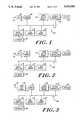
- FIG. 1is a schematic block diagram of a first embodiment of the present invention illustrating the electronic elements necessary to receive, store, process, display and transmit text or binary data over ordinary telephone lines;
- FIG. 2is a schematic block diagram of a second embodiment of the present invention illustrating the electronic elements necessary to receive, store, process and display and transmit facsimile data representing scanned pictures over telephone lines;
- FIG. 3is a schematic block diagram of a third embodiment of the present invention illustrating the electronic elements necessary to receive, store, process and display radio transmission data;
- FIG. 4is a perspective view of the miniature video display system of the present invention used to generate the full page virtual raster display
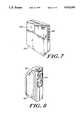
- FIG. 5is a perspective view of of the present invention illustrating a first case design and positioning within the user's hand which is shown in phantom;
- FIG. 6is a side view of the case design of FIG. 5 as held by the user for viewing purposes;
- FIG. 7is a rear perspective view of a second case design in which the raster display is positioned at an angle along the side of the case;
- FIG. 8is a side view of the second case design of FIG. 5 as held by the user for viewing purposes;
- FIG. 9is a perspective view of a third case design in which the raster display is horizontally mounted across the front of the device.
- FIG. 1is a block electrical schematic diagram of an illustrative embodiment of the data receiver circuitry which enables the data receiver to receive, store, process and retransmit data.
- an entire page of data informationmay be displayed at once on the illustrative scanning display.
- the data receiver 10A shown in FIG. 1can be used with available conventional telehone lines.
- the data receiver 10Ais connected to a conventional telephone jack by connector 22.
- Connector 22is a conventional RJ11-type modular connector which is compatible with most modern telephone jacks.
- Connector 22is connected to data access arrangement (DAA) 26.
- DAAdata access arrangement
- Device 26is a conventional hybrid circuit which is required by regulatory agencies to provide a connection to telephone lines and its construction is well-known.
- a DAA device suitable for use in the present inventionis Cermetek model 1810A available from Cermetek, Inc., 1388 Borregas Avenue, Sunnyvale, Calif. 94088.
- the output of DAA 26is provided, via signal path 27, to a modem.
- the signal path 27is shown as a single wire, it would, in fact, consist of two or more wires in order to carry the analog signals produced by DAA device 26.
- Modem 28is a conventional modulator/demodulator circuit with serial to parallel conversion capability. Modem 28 converts the analog signal produced DAA device 26 to digital data representing both data to be displayed on display unit 40 and control signals which are used by microprocessor 18 in order to format the data on display unit 40. Modem 28 further provides dialing capabilities thereby enabling the user to access data sources or to retransmit previously received data over conventional telephone lines. Microprocessor 18 provides dialing control information to modem 28 over a conventional data bus 12.
- a modem suitable for use in the present inventionis commercially available in a single integrated circuit package, Silicon Systems model K224, available from Silicon Systems, 14351 Myford Road, Tustin, Calif. 92680.
- a central microprocessor bus 12serves as both an address and data bus to interconnect the major components of data receiver 10A.
- ROM memory 16contains microprograms which are used to control the execution sequences of microprocessor 18.
- the programs stored in ROM memory 16consist of execution routines which enable receiving, storing, processing, displaying, and retransmitting of data by data receiver 10A.
- the construction and programming of a ROM memoryis conventional and will not be repeated here for clarity.
- a ROM memory storage device suitable for use in the present inventionis the Hitachi HM61364 memory device available from Hitachi America Ltd., 2210 O'Toole Avenue, San Jose 95131. Alternately, since the ROM memory 16 works in close conjunction with microprocessor 18, the ROM memory and microprocessor can be incorporated into a single processor chip.
- a random access memory (RAM) 14is further connected to bus 12.
- the data information received from modem 28 as well as control information generated by microprocessor 18are stored in RAM memory 15.
- the size of RAM memory 14may vary according to the number of desired documents or pages to be stored. A small quantity of RAM memory may be used to store only few pages and maybe upwardly expanded to store more pages.
- a low power CMOS RAM memoryis used thereby enabling retention of the memory contents with a low power drain when the rest of the data receiver 10A is powered down.
- a low powered CMOS RAM memory suitable for use in the present inventionis also commercially available as Hitachi HM6264 RAM memory available from Hitachi America Ltd.
- Microprocessor 18is connected to modem 28, ROM memory 16, RAM memory 14, frame buffer memory 30, and display controller unit 32 via bus 12.
- Microprocessor 18receives input commands from keyboard 20, serves as bus controller for bus 12 interrconnecting the major elements of device 10A, and executes microprograms stored in ROM memory 16 which enable the processes of receiving, storing, processing, displaying and retransmitting data by data receiver 10A.
- the instruction operation of microprocessor 18 in conjunction with ROM memory 16 and RAM memory 14is well known and will not be described in detail hereinafter.
- a microprocessor suitable for the present inventionis available commercially as Intel 8048 microprocessor chip from Intel Corp., 3065 Bowers Avenue, Santa Clara, Calif. 95051. Other miscellaneous hardware associated with the microprocessor such as a crystal oscillator, is not shown in FIG. 1 and is well-known and will not be described hereinafter.
- the I/O port of microprocessor 18is connected directly to keyboard 20 by signal path 17. Although shown as a single wire in FIG. 1, there are a plurality of control lines extending from keyboard 20, the actual number of which depends on the number of keys contained in keyboard 20. The interfacing of an alphanumeric keyboard with a microprocessor is well-known and will not be repeated here for brevity.
- keyboard 20may be comprised of a conventional 12-button keypad containing ten "digit" designations and two command buttons.
- the command buttonsallow the selection of a "dialing" mode or a "command" mode.
- each of the ten "digit" buttons on the keypadtakes on a secondary function in addition to the normal digit representation thereby allowing the user to control data receiver 10A.
- a smaller number of functional buttonsincluding directional buttons for moving a cursor in four directions may be provided to allow dialing control and other display commands to be selected from a menu on the display.
- a power switch(not shown) for applying power to the system may or may not be included as part of the keyboard 20.
- the power to display receiver 10Ais supplied by a conventional battery power circuit, not shown in FIG. 1. Such a power supply is well known and will not be described further in detail.
- display 40is connected to display controller 32 which is in turn connected to frame buffer memory 30. Both frame buffer memory 30 and display controller 32 are connected to bus 12.
- FIG. 4shows an illustrative embodiment of a miniature display device which is used, preferably, for raster display 40 of data receiver 10A.
- the miniature displayis of the type described in detail in co-pending U.S. patent application entitled Miniature Video Display System, filed on July 27, 1987, under Ser. No. 078,295 and assigned to the same assignee as the present invention (now U.S. Pat. No. 4,934,773) and co-pending U.S. patent application entitled Low Vibration Resonant Scanning Unit for Miniature Optical Display Apparatus filed on May 31, 1988 under Ser. No. 200,645 and assigned to the same assignee as the present invention (now U.S. Pat. No. 4,902,083).
- the display 40consists of a base 42 on which the various optical components which comprise the display are mounted. At one end of base 42 is mounted the header block 44 in which an array of light-emitting devices 46 (such as light emitting diodes) is attached. Generally, such an array may be a linear array comprising two rows of devices which ar staggered in order to compensate for gaps between the devices. The devices are covered by a clear cover plate 48.
- Light emitted from devices 46is projected via mirror 50 by means of an optical system which consists of housing 52 in which are mounted lenses 54 and 56.
- an optical systemwhich consists of housing 52 in which are mounted lenses 54 and 56.
- the lens systemprojects the enlarged virtual image of array 46 via mirror 50.
- mirror 50is oscillated by an electromechanical drive motor (not shown). The oscillation of mirror 50, in turn, creates a raster image from linear array 46.
- Frame buffer 30Under control of microprocessor 18, data stored in RAM memory 14 is transferred to frame buffer 30.
- Frame buffer 30continuously transfers the data to display controller 32 which presents the data to display 40 for displaying.
- display controller 32The operation of frame buffer 30 and display controller 32 are described in detail in the aforementioned patent application Ser. No. 078,295 and will not be discussed further in detail.
- a data receiver 10A constructed according to the present embodimentconnects to a standard telephone jack via a cable and is capable of receiving, storing, processing, displaying and retransmitting data in binary encoded forms.
- the operation of data receiver 10Agenerally works as follows.
- the user of data receiver 10Adepresses the power switch causing electrical power to be supplied to all major components of the system.
- the userthen specifies through keyboard 20 what operation he or she desires.
- Microprocessor 18then retrieves and executes the desired microprogram for the selected operation. If a display command is indicated, data stored in RAM memory 14 will be sent to frame buffer 30 under the control of microprocessor 18 via bus 12. Additional control information will be sent from microprocessor 18 to display controller 32 which will control display 40 for the appropriate display of the data. If a processing command is indicated, the microprocessor 18 will perform some operation on the data prior its sending to the frame buffer 30, such as decompressing of compressed data.
- microprocessor 18receives dialing information entered on keyboard 20 by the user. Microprocessor 18 then forwards the appropriate control information to modem 28 which in turn sends the appropriate control signals to DAA device 26. DAA device 26 sends the appropriate control signals out over the phone network for connection to the specified source. Assuming a proper connection, the appropriate control and data signals are transferred over the telephone lines to DAA device 26 and over signal path 27 to modem 28. Modem 28 converts the analog signals produced by DAA device 26 to digital signals representing data to be displayed and control signals which are used by microprocessor 18 to store the digital data in RAM memory 14.
- a transmission command signified by the userwould be executed in a similar manner except once the DAA device 26 made connection with the appropriately dialed device, data would be transferred from RAM memory 14, under the control of microprocessor 18, to modem 28, and onto DAA device 26 and the appropriate receiving device in the telephone network.
- a device 10A constructed according to the preferred embodiment described previouslyenables a user to access any kind of information which can be transmitted over conventional phone lines, view that information in a full page format, interact with the information source, and then save or retransmit that data to another device.
- data receiver 10Bwhich is designed specifically for receiving, viewing and retransmission of data from FAX machine over the telephone network.
- the data receiver 10Bwhich is specialized for connection to other FAX machines, is identical to data receiver 10A, in structure and function except that modem 28 has been replaced with special customized FAX modem 24 as shown in FIG. 2.
- FAXIn a FAX network, documents, pictures or other visual information are transmitted in the form of a compressed bit map, requiring a specialized modem and control software for interpretation of analog signals from DAA device 26.
- a FAX modem which is suitable for use in the present inventionis commercially available on a single integrated circuit device from Rockwell International Corportion, model R48MFX.
- microprocessor 18uncompresses the data stored in RAM memory 14 prior to sending it to frame buffer 30 and the other elements of the display unit for viewing by the user.
- a data receiver constructed according to data receiver 10Bis capable of receiving, displaying, and retransmitting complex graphics and other visual information, displaying them in a full page format to the user, and retransmitting the same data to another FAX device over conventional telphone lines.
- Data receiver 10Cis designed for a radio pager application.
- the specific design of data receiver 10Cdepends on the type of broadcast and desired reception.
- the varying types of radio transmissions for which the design of data receiver 10C can be tailoredinclude direct reception as in a radio pager, reception of financial information on a sub carrier of a public radio station as in Lotus Information Network, financial information, or reception of Teletex transmissions.
- data receiver 10Cis similar in structure and function to data receivers 10A and 10B except that connector 22, DAA device 26, and modem 24 have been replaced by a conventional antenna 34, a radio receiver incorporating a frequency-shift-keyed (FSK) demodulator, and a serial-to parallel converter.
- FSKfrequency-shift-keyed
- radio receiverincorporating a FSK demodulator and is its connection with antenna 34 are well known and will not be described in further detail.
- a radio receiver which is suitable for use in the present inventionis available commerically as a single integrated-circuit radio receiver available from Motorola Semiconductor Products Corporation, Phoenix, Ariz., part number MC3356.
- the tuning means and associated support circuitry, not shown in FIG. 3, required to operate the radio receiverare well known and will also not be described here in further detail.
- the analog signals produced by the radio receiver 36are transferred to a serial to parallel converter via signal path 37.
- a UARTis used for the conversion process.
- UART 38converts the stream of binary data signals produced by radio receiver 36 into bytes of digital data for transmission over bus 12 to RAM memory 14.
- UART 38converts incoming asynchronous data bits into standard data signals according to the RS-232 standard.
- a UART suitable for use in the illustrative embodimentis available from GE/Intersil incorporated as part number IM6402.
- a data receiver constructed in the manner of receiver 10Cis capable of receiving, storing, and displaying data in full page format without requiring physical connection to any network or other device, allowing for maximum mobility when using the device, but radio retransmission of stored or received data is not possible.
- data receivers 10A-COne of the primary advantages of data receivers 10A-C is that the user is able to view a full, 80-column page of data with a receiver which is physically smaller than the size of a normal page.
- the raster image which is generated by the deviceshas the appearance of a 6" ⁇ 93/8" page viewed from 24 inches away.
- the compact, pocket size of data receiver 10not only allows for true portability, but the physical shape and positioning of the viewing window enables viewing of the data with only one eye, leaving the vision of the other eye unobstructed.
- FIGS. 5-9illustrate various designs for the casing and viewing positioning of data receiver 10.
- FIG. 5illustrates a first housing embodiment in which case 60A has an elongated rectangular shape.
- case 60Acompletely surrounds the elements of the miniature video display system 40 preventing ambient light from the user's environment from permeating the case except for a single opening, display window 58A, from which the virtual image produced by the display 40 can be viewed.
- the display 40is positioned vertically within case 60A so that the virtual image viewed through display window 58A is taller than it is wide, like a sheet of paper.
- display window 58Ahas a height along the Y-axis of approximately 1 inch and a width along the X-axis of approximately 3/4 of an inch.
- case 60Ahas a height along the Y-axis of approximately 31/2 inches, a width along the X-axis of approximately 1 inch, and a depth along the Z-axis of approximately 21/2 inches.
- display window 58Amay be comprised of glass, plexiglass or clear plastic.
- Case 60Ais comprised of a light weight, yet durable material such as injection molded plastic.
- the keys comprising keyboard 20Aare positioned on the top of case 60A. The number and positioning of the keys of keyboard 20A is determined by the number of selectable functions and the designer's preference.
- the present housing embodimentis particularly well suited for the embodiment of data receivers 10A and 10B in which the dialing capability is implemented via cursor selection from a "menu" on the display
- FIG. 6illustrates a user utilizing a data receiver 10 having the first housing embodiment described above.
- the usergrasps case 60A in the palm of his hand so that at least one finger is resting on keyboard 20A.
- the case 60Ais then brought within close proximity to the desired viewing eye so that display window 58A is approximately 1 inch from the user's eye for viewing of the full page raster image.
- a focus control(not shown) is provided for focus adjustment of the displayed image to suit user prefrence.
- the usermanipulates the keys of keyboard 20A for the desired function.
- FIG. 7illustrates a second housing embodiment which is similar in size and shape to that shown in FIG. 5.
- the miniature display 40is positioned horizontally across the top of case 60B, and keyboard 20B is arranged vertically along the side of case 60B.
- display window 58is likewise mounted horizontally and has dimensions so that the screen is wider than high as with a normal computer monitor.
- the positioning and operation of this embodimetis similar to that shown in FIGS. 5 and 6 and is similarily suited for the functional designs of data receivers 10A and 10B.
- FIG. 8show yet a third housing embodiment of data receiver 10.
- case 60Cis slightly longer and narrower than case 60A or 60B.
- the miniature video display 40is positioned vertically within case 60C, however, viewing window 58C, not visible in FIG. 8, is positioned at an angle to enable easier holding by the viewer.
- the keys comprising keyboard 20C of this embodimentare positioned along the back of case 60C.
- FIG. 9illustrates a user utilizing a data receiver 10 with the housing embodiment shown in FIG. 8.
- the positioning and operation of this embodimentis similar to that shown in FIG. 6, however, when display window 58C, not shown in FIG. 9, is perpendicular to the users line of sight, case 60C rests at a comfortable angle within the user's hand.
- This particular housing embodimentallows the user easier access to keyboard 20C on the rear of case 60C and causes less finger and hand fatigue an over extended viewing period.
- the housing embodiments outlined abovemay be used in conjunction with any of the functional embodiments of data receivers 10A, 10B, or 10C and should not be restricted to the combinations suggested above.
Landscapes
- Engineering & Computer Science (AREA)
- Physics & Mathematics (AREA)
- Electromagnetism (AREA)
- General Physics & Mathematics (AREA)
- Signal Processing (AREA)
- Computer Networks & Wireless Communication (AREA)
- Human Computer Interaction (AREA)
- Mobile Radio Communication Systems (AREA)
- Control Of Indicators Other Than Cathode Ray Tubes (AREA)
- Circuits Of Receivers In General (AREA)
- Devices For Indicating Variable Information By Combining Individual Elements (AREA)
- Structure Of Receivers (AREA)
- Telephone Set Structure (AREA)
- Transforming Electric Information Into Light Information (AREA)
- Measurement Of The Respiration, Hearing Ability, Form, And Blood Characteristics Of Living Organisms (AREA)
- Calculators And Similar Devices (AREA)
- Display Devices Of Pinball Game Machines (AREA)
Abstract
Description
Claims (21)
Priority Applications (8)
| Application Number | Priority Date | Filing Date | Title |
|---|---|---|---|
| US07/223,833US5023905A (en) | 1988-07-25 | 1988-07-25 | Pocket data receiver with full page visual display |
| ES89306703TES2079379T3 (en) | 1988-07-25 | 1989-06-30 | POCKET DATA RECEIVER WITH FULL PAGE VISUAL PRESENTATION. |
| DE68924935TDE68924935T2 (en) | 1988-07-25 | 1989-06-30 | Pocket data receiver with full-page visual display. |
| EP89306703AEP0352913B1 (en) | 1988-07-25 | 1989-06-30 | Pocket data receiver with full page visual display |
| AT89306703TATE130990T1 (en) | 1988-07-25 | 1989-06-30 | POCKET DATA RECEIVER WITH FULL SIDE DISPLAY. |
| AU38881/89AAU622203B2 (en) | 1988-07-25 | 1989-07-24 | Pocket pager with full-page visual display |
| CA000606628ACA1316616C (en) | 1988-07-25 | 1989-07-25 | Pocket data receiver with full page visual display |
| JP1192451AJP2918244B2 (en) | 1988-07-25 | 1989-07-25 | Portable data receiver |
Applications Claiming Priority (1)
| Application Number | Priority Date | Filing Date | Title |
|---|---|---|---|
| US07/223,833US5023905A (en) | 1988-07-25 | 1988-07-25 | Pocket data receiver with full page visual display |
Publications (1)
| Publication Number | Publication Date |
|---|---|
| US5023905Atrue US5023905A (en) | 1991-06-11 |
Family
ID=22838142
Family Applications (1)
| Application Number | Title | Priority Date | Filing Date |
|---|---|---|---|
| US07/223,833Expired - LifetimeUS5023905A (en) | 1988-07-25 | 1988-07-25 | Pocket data receiver with full page visual display |
Country Status (8)
| Country | Link |
|---|---|
| US (1) | US5023905A (en) |
| EP (1) | EP0352913B1 (en) |
| JP (1) | JP2918244B2 (en) |
| AT (1) | ATE130990T1 (en) |
| AU (1) | AU622203B2 (en) |
| CA (1) | CA1316616C (en) |
| DE (1) | DE68924935T2 (en) |
| ES (1) | ES2079379T3 (en) |
Cited By (92)
| Publication number | Priority date | Publication date | Assignee | Title |
|---|---|---|---|---|
| WO1992011615A1 (en)* | 1990-12-21 | 1992-07-09 | Motorola, Inc. | Facsimile paging system |
| WO1993021673A1 (en)* | 1992-04-21 | 1993-10-28 | Bandgap Technology Corporation | Vertical-cavity surface-emitting laser abray display system |
| US5260867A (en)* | 1986-09-30 | 1993-11-09 | Maeser William C | Portable transceiver |
| US5285493A (en)* | 1989-01-19 | 1994-02-08 | Kabushiki Kaisha Toshiba | Radio tele-communication device with received message displaying feature |
| US5398115A (en)* | 1994-02-24 | 1995-03-14 | Lin; Iyh-Han | Facsimile communication for locating and transmitting information from a document to selective call receivers |
| US5446678A (en)* | 1992-12-18 | 1995-08-29 | Hewlett-Packard Corporation | Transmission of information over an alphanumeric paging network |
| US5592606A (en)* | 1993-07-30 | 1997-01-07 | Myers; Allen | Method and apparatus for storage and display of hierarchally organized data |
| US5684865A (en)* | 1995-08-28 | 1997-11-04 | Motorola, Inc. | Method for efficient facsimile communication with selective call receivers |
| US5687222A (en)* | 1994-07-05 | 1997-11-11 | Nxi Communications, Inc. | ITU/TDD modem |
| US5742421A (en)* | 1996-03-01 | 1998-04-21 | Reflection Technology, Inc. | Split lens video display system |
| US5758293A (en)* | 1996-03-06 | 1998-05-26 | Motorola Inc. | Subscriber unit and delivery system for wireless information retrieval |
| US5769643A (en)* | 1996-02-07 | 1998-06-23 | Ncr Corporation | Instruction communication system |
| US5821911A (en)* | 1993-09-07 | 1998-10-13 | Motorola | Miniature virtual image color display |
| US5838798A (en)* | 1996-02-07 | 1998-11-17 | Ncr Corporation | Restaurant transaction processing system and method |
| US5905476A (en)* | 1994-07-05 | 1999-05-18 | Nxi Communications, Inc. | ITU/TDD modem |
| US5933764A (en)* | 1996-05-28 | 1999-08-03 | Nec Corporation | Password-protected pager |
| US5956656A (en)* | 1996-04-22 | 1999-09-21 | Nec Corporation | Wireless selective call receiver operable in cover closing state |
| US5970418A (en)* | 1995-09-21 | 1999-10-19 | International Business Machines Corporation | Personal communicator including a handset phone with an integrated virtual image display |
| US6049354A (en)* | 1993-10-19 | 2000-04-11 | Canon Kabushiki Kaisha | Image shake-correcting system with selective image-shake correction |
| US6097935A (en)* | 1995-11-10 | 2000-08-01 | Casio Computer Co., Ltd. | Data receiver apparatus |
| US6138036A (en)* | 1997-03-13 | 2000-10-24 | Oki Telecom, Inc. | Wireless telephone with voice data interface mode |
| US6140981A (en)* | 1997-03-20 | 2000-10-31 | Kuenster; Gordon B. | Body-mountable display system |
| US6157353A (en)* | 1991-09-30 | 2000-12-05 | Motorola, Inc. | Receiver with miniature virtual image display |
| US6181736B1 (en) | 1997-03-25 | 2001-01-30 | Nxi Communications, Inc. | Network communication system |
| US6243056B1 (en)* | 1993-10-04 | 2001-06-05 | Motorola, Inc. | Transceiver with miniature virtual image display |
| US6247150B1 (en)* | 1998-07-03 | 2001-06-12 | Nokia Networks Oy | Automatic retransmission with order of information changed |
| US6330334B1 (en) | 1993-03-15 | 2001-12-11 | Command Audio Corporation | Method and system for information dissemination using television signals |
| US20020025832A1 (en)* | 2000-02-18 | 2002-02-28 | Durian Michael B. | Controlling data transmission involving a wireless telephone |
| US6359609B1 (en) | 1997-03-20 | 2002-03-19 | Gordon B. Kuenster | Body-mountable display system |
| US20030076352A1 (en)* | 2001-10-22 | 2003-04-24 | Uhlig Ronald P. | Note taking, organizing, and studying software |
| US6707591B2 (en) | 2001-04-10 | 2004-03-16 | Silicon Light Machines | Angled illumination for a single order light modulator based projection system |
| US6714337B1 (en) | 2002-06-28 | 2004-03-30 | Silicon Light Machines | Method and device for modulating a light beam and having an improved gamma response |
| US6712480B1 (en) | 2002-09-27 | 2004-03-30 | Silicon Light Machines | Controlled curvature of stressed micro-structures |
| US6728023B1 (en) | 2002-05-28 | 2004-04-27 | Silicon Light Machines | Optical device arrays with optimized image resolution |
| US6747781B2 (en) | 2001-06-25 | 2004-06-08 | Silicon Light Machines, Inc. | Method, apparatus, and diffuser for reducing laser speckle |
| US6764875B2 (en) | 1998-07-29 | 2004-07-20 | Silicon Light Machines | Method of and apparatus for sealing an hermetic lid to a semiconductor die |
| US6767751B2 (en) | 2002-05-28 | 2004-07-27 | Silicon Light Machines, Inc. | Integrated driver process flow |
| US6782205B2 (en) | 2001-06-25 | 2004-08-24 | Silicon Light Machines | Method and apparatus for dynamic equalization in wavelength division multiplexing |
| US6801354B1 (en) | 2002-08-20 | 2004-10-05 | Silicon Light Machines, Inc. | 2-D diffraction grating for substantially eliminating polarization dependent losses |
| US6800238B1 (en) | 2002-01-15 | 2004-10-05 | Silicon Light Machines, Inc. | Method for domain patterning in low coercive field ferroelectrics |
| US6806997B1 (en) | 2003-02-28 | 2004-10-19 | Silicon Light Machines, Inc. | Patterned diffractive light modulator ribbon for PDL reduction |
| US6813059B2 (en) | 2002-06-28 | 2004-11-02 | Silicon Light Machines, Inc. | Reduced formation of asperities in contact micro-structures |
| US6822797B1 (en) | 2002-05-31 | 2004-11-23 | Silicon Light Machines, Inc. | Light modulator structure for producing high-contrast operation using zero-order light |
| US6829258B1 (en) | 2002-06-26 | 2004-12-07 | Silicon Light Machines, Inc. | Rapidly tunable external cavity laser |
| US6829092B2 (en) | 2001-08-15 | 2004-12-07 | Silicon Light Machines, Inc. | Blazed grating light valve |
| US6829077B1 (en) | 2003-02-28 | 2004-12-07 | Silicon Light Machines, Inc. | Diffractive light modulator with dynamically rotatable diffraction plane |
| US6865346B1 (en) | 2001-06-05 | 2005-03-08 | Silicon Light Machines Corporation | Fiber optic transceiver |
| US6872984B1 (en) | 1998-07-29 | 2005-03-29 | Silicon Light Machines Corporation | Method of sealing a hermetic lid to a semiconductor die at an angle |
| US6908201B2 (en) | 2002-06-28 | 2005-06-21 | Silicon Light Machines Corporation | Micro-support structures |
| US6922272B1 (en) | 2003-02-14 | 2005-07-26 | Silicon Light Machines Corporation | Method and apparatus for leveling thermal stress variations in multi-layer MEMS devices |
| US6922273B1 (en) | 2003-02-28 | 2005-07-26 | Silicon Light Machines Corporation | PDL mitigation structure for diffractive MEMS and gratings |
| US6927891B1 (en) | 2002-12-23 | 2005-08-09 | Silicon Light Machines Corporation | Tilt-able grating plane for improved crosstalk in 1×N blaze switches |
| US6928207B1 (en) | 2002-12-12 | 2005-08-09 | Silicon Light Machines Corporation | Apparatus for selectively blocking WDM channels |
| US6934070B1 (en) | 2002-12-18 | 2005-08-23 | Silicon Light Machines Corporation | Chirped optical MEM device |
| US6947613B1 (en) | 2003-02-11 | 2005-09-20 | Silicon Light Machines Corporation | Wavelength selective switch and equalizer |
| US6956995B1 (en) | 2001-11-09 | 2005-10-18 | Silicon Light Machines Corporation | Optical communication arrangement |
| US6956878B1 (en) | 2000-02-07 | 2005-10-18 | Silicon Light Machines Corporation | Method and apparatus for reducing laser speckle using polarization averaging |
| US20050264502A1 (en)* | 2004-05-07 | 2005-12-01 | Sprague Randall B | Scanned light display system using large numerical aperture light source, method of using same, and method of making scanning mirror assemblies |
| US6987600B1 (en) | 2002-12-17 | 2006-01-17 | Silicon Light Machines Corporation | Arbitrary phase profile for better equalization in dynamic gain equalizer |
| US20060017655A1 (en)* | 2004-07-21 | 2006-01-26 | Microvision, Inc. | Scanned beam system and method using a plurality of display zones |
| US6991953B1 (en) | 2001-09-13 | 2006-01-31 | Silicon Light Machines Corporation | Microelectronic mechanical system and methods |
| US20060061846A1 (en)* | 2004-09-17 | 2006-03-23 | Microvision, Inc. | Scanned light display system using array of collimating elements in conjunction with large numerical aperture light emitter array |
| US7027202B1 (en) | 2003-02-28 | 2006-04-11 | Silicon Light Machines Corp | Silicon substrate as a light modulator sacrificial layer |
| US7042611B1 (en) | 2003-03-03 | 2006-05-09 | Silicon Light Machines Corporation | Pre-deflected bias ribbons |
| US7054515B1 (en) | 2002-05-30 | 2006-05-30 | Silicon Light Machines Corporation | Diffractive light modulator-based dynamic equalizer with integrated spectral monitor |
| US7057795B2 (en) | 2002-08-20 | 2006-06-06 | Silicon Light Machines Corporation | Micro-structures with individually addressable ribbon pairs |
| US7057819B1 (en) | 2002-12-17 | 2006-06-06 | Silicon Light Machines Corporation | High contrast tilting ribbon blazed grating |
| US7068372B1 (en) | 2003-01-28 | 2006-06-27 | Silicon Light Machines Corporation | MEMS interferometer-based reconfigurable optical add-and-drop multiplexor |
| US7177081B2 (en) | 2001-03-08 | 2007-02-13 | Silicon Light Machines Corporation | High contrast grating light valve type device |
| US20070070419A1 (en)* | 1992-11-09 | 2007-03-29 | Toshiharu Enmei | Portable communicator |
| US7266186B1 (en)* | 1994-01-05 | 2007-09-04 | Intellect Wireless Inc. | Method and apparatus for improved paging receiver and system |
| US7286764B1 (en) | 2003-02-03 | 2007-10-23 | Silicon Light Machines Corporation | Reconfigurable modulator-based optical add-and-drop multiplexer |
| US20070275708A1 (en)* | 1994-01-05 | 2007-11-29 | Henderson Daniel A | Method and apparatus for improved personal communication devices and systems |
| US20080018641A1 (en)* | 2006-03-07 | 2008-01-24 | Sprague Randall B | Display configured for varying the apparent depth of selected pixels |
| US20080043487A1 (en)* | 2006-08-21 | 2008-02-21 | Sprague Randall B | Light bar structure having light conduits and scanned light display system employing same |
| US7391973B1 (en) | 2003-02-28 | 2008-06-24 | Silicon Light Machines Corporation | Two-stage gain equalizer |
| US20080255458A1 (en)* | 2007-04-13 | 2008-10-16 | Ethicon Endo-Surgery, Inc. | System and method using fluorescence to examine within a patient's anatomy |
| US7561317B2 (en) | 2006-11-03 | 2009-07-14 | Ethicon Endo-Surgery, Inc. | Resonant Fourier scanning |
| US7589316B2 (en) | 2007-01-18 | 2009-09-15 | Ethicon Endo-Surgery, Inc. | Scanning beam imaging with adjustable detector sensitivity or gain |
| US7713265B2 (en) | 2006-12-22 | 2010-05-11 | Ethicon Endo-Surgery, Inc. | Apparatus and method for medically treating a tattoo |
| US7925333B2 (en) | 2007-08-28 | 2011-04-12 | Ethicon Endo-Surgery, Inc. | Medical device including scanned beam unit with operational control features |
| US7982776B2 (en) | 2007-07-13 | 2011-07-19 | Ethicon Endo-Surgery, Inc. | SBI motion artifact removal apparatus and method |
| US7983739B2 (en) | 2007-08-27 | 2011-07-19 | Ethicon Endo-Surgery, Inc. | Position tracking and control for a scanning assembly |
| US7995045B2 (en) | 2007-04-13 | 2011-08-09 | Ethicon Endo-Surgery, Inc. | Combined SBI and conventional image processor |
| US8050520B2 (en) | 2008-03-27 | 2011-11-01 | Ethicon Endo-Surgery, Inc. | Method for creating a pixel image from sampled data of a scanned beam imager |
| US8160678B2 (en) | 2007-06-18 | 2012-04-17 | Ethicon Endo-Surgery, Inc. | Methods and devices for repairing damaged or diseased tissue using a scanning beam assembly |
| US8216214B2 (en) | 2007-03-12 | 2012-07-10 | Ethicon Endo-Surgery, Inc. | Power modulation of a scanning beam for imaging, therapy, and/or diagnosis |
| US8273015B2 (en) | 2007-01-09 | 2012-09-25 | Ethicon Endo-Surgery, Inc. | Methods for imaging the anatomy with an anatomically secured scanner assembly |
| US8332014B2 (en) | 2008-04-25 | 2012-12-11 | Ethicon Endo-Surgery, Inc. | Scanned beam device and method using same which measures the reflectance of patient tissue |
| US8801606B2 (en) | 2007-01-09 | 2014-08-12 | Ethicon Endo-Surgery, Inc. | Method of in vivo monitoring using an imaging system including scanned beam imaging unit |
| US9079762B2 (en) | 2006-09-22 | 2015-07-14 | Ethicon Endo-Surgery, Inc. | Micro-electromechanical device |
| US9125552B2 (en) | 2007-07-31 | 2015-09-08 | Ethicon Endo-Surgery, Inc. | Optical scanning module and means for attaching the module to medical instruments for introducing the module into the anatomy |
Families Citing this family (4)
| Publication number | Priority date | Publication date | Assignee | Title |
|---|---|---|---|---|
| CH681398A5 (en)* | 1990-08-23 | 1993-03-15 | Erika Koechler | Transmitting digitally coded signals in radio paging network - allowing transmission of graphical image information as binary sequence representing individual image points |
| JP3747489B2 (en)* | 1995-02-08 | 2006-02-22 | カシオ計算機株式会社 | Multiple broadcast receiver and received information display method |
| TW320717B (en)* | 1995-11-13 | 1997-11-21 | Motorola Inc | |
| CN114111637B (en)* | 2021-11-25 | 2024-06-21 | 天津工业大学 | Virtual dual-purpose stripe structured light three-dimensional reconstruction method |
Citations (56)
| Publication number | Priority date | Publication date | Assignee | Title |
|---|---|---|---|---|
| US1756232A (en)* | 1928-02-17 | 1930-04-29 | Arnaud Joseph John | Television apparatus |
| US1766885A (en)* | 1923-11-29 | 1930-06-24 | Dauvillier Alexandre | Television system |
| US1979296A (en)* | 1931-10-19 | 1934-11-06 | William H Sweeney | Television apparatus |
| US2681588A (en)* | 1952-04-08 | 1954-06-22 | Biddle Co James G | Vibrating reed device |
| US3059519A (en)* | 1956-09-05 | 1962-10-23 | Austin N Stanton | Headgear mounted cathode ray tube and binocular viewing device |
| US3079555A (en)* | 1958-01-21 | 1963-02-26 | J B T Instr Inc | Vibrating reed electro-responsive device |
| US3170979A (en)* | 1962-04-30 | 1965-02-23 | Alan W Baldwin | Optical image interposing display device |
| US3205303A (en)* | 1961-03-27 | 1965-09-07 | Philco Corp | Remotely controlled remote viewing system |
| US3446980A (en)* | 1965-09-22 | 1969-05-27 | Philco Ford Corp | Stabilized sight system employing autocollimation of gyro-stabilized light beam to correct yaw and pitch orientation of coupled sight line and servo system mirrors |
| US3532408A (en)* | 1968-05-20 | 1970-10-06 | Bulova Watch Co Inc | Resonant torsional oscillators |
| US3609485A (en)* | 1969-04-09 | 1971-09-28 | Bulova Watch Co Inc | Resonant torsional oscillators |
| US3671766A (en)* | 1970-06-29 | 1972-06-20 | Hughes Aircraft Co | Oscillating mechanism |
| US3742238A (en)* | 1970-12-14 | 1973-06-26 | Texas Instruments Inc | Two axes angularly indexing scanning display |
| US3760181A (en)* | 1972-03-03 | 1973-09-18 | Us Army | Universal viewer for far infrared |
| US3781559A (en)* | 1972-06-19 | 1973-12-25 | Texas Instruments Inc | Variable field of view scanning system |
| US3833300A (en)* | 1973-05-14 | 1974-09-03 | Us Navy | Three {37 d{38 {11 weapons sight |
| US3846784A (en)* | 1972-05-22 | 1974-11-05 | C Sinclair | Electronic digital displays |
| US3923370A (en)* | 1974-10-15 | 1975-12-02 | Honeywell Inc | Head mounted displays |
| US3958235A (en)* | 1974-07-26 | 1976-05-18 | Duffy Francis A | Light emitting diode display apparatus and system |
| USRE28847E (en)* | 1972-06-28 | 1976-06-08 | Honeywell Inc. | Inside helmet sight display apparatus |
| US4026641A (en)* | 1975-12-30 | 1977-05-31 | The United States Of America As Represented By The Secretary Of The Army | Toric reflector display |
| US4081209A (en)* | 1975-04-29 | 1978-03-28 | Elliott Brothers (London) Limited | Headgear with spherical semi-reflecting surface |
| US4225862A (en)* | 1979-03-05 | 1980-09-30 | International Business Machines Corporation | Tuning fork oscillator driven light emitting diode display unit |
| US4232196A (en)* | 1978-12-27 | 1980-11-04 | Frederico Filippi | Video telephone apparatus |
| US4248495A (en)* | 1978-05-08 | 1981-02-03 | Canon Kabushiki Kaisha | Projecting optical system with deflected optical axis maintained parallel to next optical axis |
| US4251126A (en)* | 1978-06-06 | 1981-02-17 | Canon Kabushiki Kaisha | Light beam scanning device with opposed deflecting surfaces |
| JPS5630677A (en)* | 1979-08-22 | 1981-03-27 | Matsushita Electric Ind Co Ltd | Automatic luminance regulator |
| US4268721A (en)* | 1977-05-02 | 1981-05-19 | Sri International | Portable telephone communication device for the hearing impaired |
| US4311999A (en)* | 1980-02-07 | 1982-01-19 | Textron, Inc. | Vibratory scan optical display |
| JPS57114116A (en)* | 1981-01-07 | 1982-07-15 | Canon Inc | Image forming device |
| US4340888A (en)* | 1980-04-01 | 1982-07-20 | Martin Marietta Corporation | Scan linerization method and device |
| US4364636A (en)* | 1979-11-09 | 1982-12-21 | Elliott Brothers (London) Limited | Helmet mounted sight with fixed display and pivotal arm |
| US4415065A (en)* | 1980-11-17 | 1983-11-15 | Sandstedt Gary O | Restaurant or retail vending facility |
| US4439157A (en)* | 1982-05-03 | 1984-03-27 | The United States Of America As Represented By The Secretary Of The Navy | Helmet mounted display projector |
| US4442318A (en)* | 1982-08-20 | 1984-04-10 | Desrochers Franklin J | Portable bi-directional data communication terminal |
| US4443075A (en)* | 1981-06-26 | 1984-04-17 | Sri International | Stabilized visual system |
| US4457580A (en)* | 1980-07-11 | 1984-07-03 | Mattel, Inc. | Display for electronic games and the like including a rotating focusing device |
| US4470044A (en)* | 1981-05-15 | 1984-09-04 | Bill Bell | Momentary visual image apparatus |
| EP0121927A2 (en)* | 1983-04-12 | 1984-10-17 | Siemens Aktiengesellschaft | Control equipment for a car telephone |
| US4538181A (en)* | 1983-02-28 | 1985-08-27 | Kollmorgen Technologies | Optical scanner |
| US4618860A (en)* | 1982-05-31 | 1986-10-21 | Nec Corporation | Radio paging method of arranging message information with reference to a key code and a base station and a pager receiver for use in the method |
| WO1986006238A1 (en)* | 1985-04-16 | 1986-10-23 | Telebeam International Limited | Text receiver |
| US4632501A (en)* | 1984-02-16 | 1986-12-30 | General Scanning, Inc. | Resonant electromechanical oscillator |
| US4636866A (en)* | 1982-12-24 | 1987-01-13 | Seiko Epson K.K. | Personal liquid crystal image display |
| USRE32365E (en)* | 1975-05-22 | 1987-03-03 | Sanders Associates, Inc. | Precessing display pager |
| US4661659A (en)* | 1982-11-30 | 1987-04-28 | Sharp Kabushiki Kaisha | Wireless phone system communicatively combined with a computer |
| US4676582A (en)* | 1982-02-18 | 1987-06-30 | Fuji Photo Film Co., Ltd. | Radiation image read-out and reproducing apparatus |
| US4708420A (en)* | 1984-05-24 | 1987-11-24 | The Commonwealth Of Australia | Focal plane scanning device |
| US4720781A (en)* | 1983-11-30 | 1988-01-19 | Stc Plc | Data processing terminal having support module and portable display module for liquid crystal display |
| US4732440A (en)* | 1985-10-22 | 1988-03-22 | Gadhok Jagmohan S | Self resonant scanning device |
| USD295411S (en) | 1985-03-15 | 1988-04-26 | American Telephone And Telegraph Company, At&T Bell Laboratories | Combined voice and data terminal or similar article |
| US4752129A (en)* | 1985-03-27 | 1988-06-21 | Anritsu Corporation | Wavelength modulation derivative spectrometer |
| US4753514A (en)* | 1986-05-12 | 1988-06-28 | Iota Instrumentation Co. | Headwear-mounted periscopic display device |
| US4795223A (en)* | 1987-01-06 | 1989-01-03 | Hughes Aircraft Company | Segmented 3-D hologram display |
| EP0301801A2 (en)* | 1987-07-27 | 1989-02-01 | Reflection Technology, Inc. | Miniature video display system |
| US4837811A (en)* | 1988-01-25 | 1989-06-06 | Communication Manufacturing Co. | Telephone technician's terminals |
Family Cites Families (2)
| Publication number | Priority date | Publication date | Assignee | Title |
|---|---|---|---|---|
| US4692878A (en)* | 1985-03-29 | 1987-09-08 | Ampower Technologies, Inc. | Three-dimensional spatial image system |
| US4902083A (en)* | 1988-05-31 | 1990-02-20 | Reflection Technology, Inc. | Low vibration resonant scanning unit for miniature optical display apparatus |
- 1988
- 1988-07-25USUS07/223,833patent/US5023905A/ennot_activeExpired - Lifetime
- 1989
- 1989-06-30DEDE68924935Tpatent/DE68924935T2/ennot_activeExpired - Fee Related
- 1989-06-30ATAT89306703Tpatent/ATE130990T1/enactive
- 1989-06-30EPEP89306703Apatent/EP0352913B1/ennot_activeExpired - Lifetime
- 1989-06-30ESES89306703Tpatent/ES2079379T3/ennot_activeExpired - Lifetime
- 1989-07-24AUAU38881/89Apatent/AU622203B2/ennot_activeCeased
- 1989-07-25JPJP1192451Apatent/JP2918244B2/ennot_activeExpired - Lifetime
- 1989-07-25CACA000606628Apatent/CA1316616C/ennot_activeExpired - Fee Related
Patent Citations (56)
| Publication number | Priority date | Publication date | Assignee | Title |
|---|---|---|---|---|
| US1766885A (en)* | 1923-11-29 | 1930-06-24 | Dauvillier Alexandre | Television system |
| US1756232A (en)* | 1928-02-17 | 1930-04-29 | Arnaud Joseph John | Television apparatus |
| US1979296A (en)* | 1931-10-19 | 1934-11-06 | William H Sweeney | Television apparatus |
| US2681588A (en)* | 1952-04-08 | 1954-06-22 | Biddle Co James G | Vibrating reed device |
| US3059519A (en)* | 1956-09-05 | 1962-10-23 | Austin N Stanton | Headgear mounted cathode ray tube and binocular viewing device |
| US3079555A (en)* | 1958-01-21 | 1963-02-26 | J B T Instr Inc | Vibrating reed electro-responsive device |
| US3205303A (en)* | 1961-03-27 | 1965-09-07 | Philco Corp | Remotely controlled remote viewing system |
| US3170979A (en)* | 1962-04-30 | 1965-02-23 | Alan W Baldwin | Optical image interposing display device |
| US3446980A (en)* | 1965-09-22 | 1969-05-27 | Philco Ford Corp | Stabilized sight system employing autocollimation of gyro-stabilized light beam to correct yaw and pitch orientation of coupled sight line and servo system mirrors |
| US3532408A (en)* | 1968-05-20 | 1970-10-06 | Bulova Watch Co Inc | Resonant torsional oscillators |
| US3609485A (en)* | 1969-04-09 | 1971-09-28 | Bulova Watch Co Inc | Resonant torsional oscillators |
| US3671766A (en)* | 1970-06-29 | 1972-06-20 | Hughes Aircraft Co | Oscillating mechanism |
| US3742238A (en)* | 1970-12-14 | 1973-06-26 | Texas Instruments Inc | Two axes angularly indexing scanning display |
| US3760181A (en)* | 1972-03-03 | 1973-09-18 | Us Army | Universal viewer for far infrared |
| US3846784A (en)* | 1972-05-22 | 1974-11-05 | C Sinclair | Electronic digital displays |
| US3781559A (en)* | 1972-06-19 | 1973-12-25 | Texas Instruments Inc | Variable field of view scanning system |
| USRE28847E (en)* | 1972-06-28 | 1976-06-08 | Honeywell Inc. | Inside helmet sight display apparatus |
| US3833300A (en)* | 1973-05-14 | 1974-09-03 | Us Navy | Three {37 d{38 {11 weapons sight |
| US3958235A (en)* | 1974-07-26 | 1976-05-18 | Duffy Francis A | Light emitting diode display apparatus and system |
| US3923370A (en)* | 1974-10-15 | 1975-12-02 | Honeywell Inc | Head mounted displays |
| US4081209A (en)* | 1975-04-29 | 1978-03-28 | Elliott Brothers (London) Limited | Headgear with spherical semi-reflecting surface |
| USRE32365E (en)* | 1975-05-22 | 1987-03-03 | Sanders Associates, Inc. | Precessing display pager |
| US4026641A (en)* | 1975-12-30 | 1977-05-31 | The United States Of America As Represented By The Secretary Of The Army | Toric reflector display |
| US4268721A (en)* | 1977-05-02 | 1981-05-19 | Sri International | Portable telephone communication device for the hearing impaired |
| US4248495A (en)* | 1978-05-08 | 1981-02-03 | Canon Kabushiki Kaisha | Projecting optical system with deflected optical axis maintained parallel to next optical axis |
| US4251126A (en)* | 1978-06-06 | 1981-02-17 | Canon Kabushiki Kaisha | Light beam scanning device with opposed deflecting surfaces |
| US4232196A (en)* | 1978-12-27 | 1980-11-04 | Frederico Filippi | Video telephone apparatus |
| US4225862A (en)* | 1979-03-05 | 1980-09-30 | International Business Machines Corporation | Tuning fork oscillator driven light emitting diode display unit |
| JPS5630677A (en)* | 1979-08-22 | 1981-03-27 | Matsushita Electric Ind Co Ltd | Automatic luminance regulator |
| US4364636A (en)* | 1979-11-09 | 1982-12-21 | Elliott Brothers (London) Limited | Helmet mounted sight with fixed display and pivotal arm |
| US4311999A (en)* | 1980-02-07 | 1982-01-19 | Textron, Inc. | Vibratory scan optical display |
| US4340888A (en)* | 1980-04-01 | 1982-07-20 | Martin Marietta Corporation | Scan linerization method and device |
| US4457580A (en)* | 1980-07-11 | 1984-07-03 | Mattel, Inc. | Display for electronic games and the like including a rotating focusing device |
| US4415065A (en)* | 1980-11-17 | 1983-11-15 | Sandstedt Gary O | Restaurant or retail vending facility |
| JPS57114116A (en)* | 1981-01-07 | 1982-07-15 | Canon Inc | Image forming device |
| US4470044A (en)* | 1981-05-15 | 1984-09-04 | Bill Bell | Momentary visual image apparatus |
| US4443075A (en)* | 1981-06-26 | 1984-04-17 | Sri International | Stabilized visual system |
| US4676582A (en)* | 1982-02-18 | 1987-06-30 | Fuji Photo Film Co., Ltd. | Radiation image read-out and reproducing apparatus |
| US4439157A (en)* | 1982-05-03 | 1984-03-27 | The United States Of America As Represented By The Secretary Of The Navy | Helmet mounted display projector |
| US4618860A (en)* | 1982-05-31 | 1986-10-21 | Nec Corporation | Radio paging method of arranging message information with reference to a key code and a base station and a pager receiver for use in the method |
| US4442318A (en)* | 1982-08-20 | 1984-04-10 | Desrochers Franklin J | Portable bi-directional data communication terminal |
| US4661659A (en)* | 1982-11-30 | 1987-04-28 | Sharp Kabushiki Kaisha | Wireless phone system communicatively combined with a computer |
| US4636866A (en)* | 1982-12-24 | 1987-01-13 | Seiko Epson K.K. | Personal liquid crystal image display |
| US4538181A (en)* | 1983-02-28 | 1985-08-27 | Kollmorgen Technologies | Optical scanner |
| EP0121927A2 (en)* | 1983-04-12 | 1984-10-17 | Siemens Aktiengesellschaft | Control equipment for a car telephone |
| US4720781A (en)* | 1983-11-30 | 1988-01-19 | Stc Plc | Data processing terminal having support module and portable display module for liquid crystal display |
| US4632501A (en)* | 1984-02-16 | 1986-12-30 | General Scanning, Inc. | Resonant electromechanical oscillator |
| US4708420A (en)* | 1984-05-24 | 1987-11-24 | The Commonwealth Of Australia | Focal plane scanning device |
| USD295411S (en) | 1985-03-15 | 1988-04-26 | American Telephone And Telegraph Company, At&T Bell Laboratories | Combined voice and data terminal or similar article |
| US4752129A (en)* | 1985-03-27 | 1988-06-21 | Anritsu Corporation | Wavelength modulation derivative spectrometer |
| WO1986006238A1 (en)* | 1985-04-16 | 1986-10-23 | Telebeam International Limited | Text receiver |
| US4732440A (en)* | 1985-10-22 | 1988-03-22 | Gadhok Jagmohan S | Self resonant scanning device |
| US4753514A (en)* | 1986-05-12 | 1988-06-28 | Iota Instrumentation Co. | Headwear-mounted periscopic display device |
| US4795223A (en)* | 1987-01-06 | 1989-01-03 | Hughes Aircraft Company | Segmented 3-D hologram display |
| EP0301801A2 (en)* | 1987-07-27 | 1989-02-01 | Reflection Technology, Inc. | Miniature video display system |
| US4837811A (en)* | 1988-01-25 | 1989-06-06 | Communication Manufacturing Co. | Telephone technician's terminals |
Non-Patent Citations (20)
| Title |
|---|
| Conversational Terminal, Cermetek Microelectronics, 4/87.* |
| Invention Disclosure, "Beam Stabilization and Auto Alignment System," Hughes Aircraft Company, 9/76, Report No. P76-361. |
| Invention Disclosure, Beam Stabilization and Auto Alignment System, Hughes Aircraft Company, 9/76, Report No. P76 361.* |
| Invention Disclosure, Fritzel, et al., "I.D.C. Reactionless Mirror Drive Concept", Hughes Aircraft Company, May 1975. |
| Invention Disclosure, Fritzel, et al., I.D.C. Reactionless Mirror Drive Concept , Hughes Aircraft Company, May 1975.* |
| Leon, N. M., "Projectd Image Display," 6/79, IBM Technical Disclosure Bulletin, vol. 22, No. 1, pp. 363-365. |
| Leon, N. M., Projectd Image Display, 6/79, IBM Technical Disclosure Bulletin, vol. 22, No. 1, pp. 363 365.* |
| Lifestyle Personal Communicator, AdioBionics Inc., Hearing Instruments, vol. 36, No. 1, 1985.* |
| Machine Design, 6/12/86, "Lineman's Handset Answers All Question," p. 46. |
| Machine Design, 6/12/86, Lineman s Handset Answers All Question, p. 46.* |
| OKI Technical Review 123, vol. 52, publication "High-Resolution Display Using Light-Emitting Diode Arrays," Abiko, et al., 1/86, pp. 46-50. |
| OKI Technical Review 123, vol. 52, publication High Resolution Display Using Light Emitting Diode Arrays, Abiko, et al., 1/86, pp. 46 50.* |
| Reid, D. A. T., "Micro-Display," 6/79, IBM Technical Disclosure Bulletin, vol. 22, No. 1, p. 362. |
| Reid, D. A. T., Micro Display, 6/79, IBM Technical Disclosure Bulletin, vol. 22, No. 1, p. 362.* |
| Title "IRTV-445 Patented Scanning System", Inframetrics Night Vision Systems Group, Bedford, MA. |
| Title IRTV 445 Patented Scanning System , Inframetrics Night Vision Systems Group, Bedford, MA.* |
| Upton, Hubert W. and Goodman, J. R., "Eyeglass Heads-Up Display," Proceedings of the SID, vol. 23/2, 1982, pp. 77-80. |
| Upton, Hubert W. and Goodman, J. R., Eyeglass Heads Up Display, Proceedings of the SID, vol. 23/2, 1982, pp. 77 80.* |
| Upton, Hubert W. and Goodman, James R., "Eyeglass Heads-Up Display," SID 81 Digest, pp. 48, 49. |
| Upton, Hubert W. and Goodman, James R., Eyeglass Heads Up Display, SID 81 Digest, pp. 48, 49.* |
Cited By (118)
| Publication number | Priority date | Publication date | Assignee | Title |
|---|---|---|---|---|
| US5260867A (en)* | 1986-09-30 | 1993-11-09 | Maeser William C | Portable transceiver |
| US5285493A (en)* | 1989-01-19 | 1994-02-08 | Kabushiki Kaisha Toshiba | Radio tele-communication device with received message displaying feature |
| WO1992011615A1 (en)* | 1990-12-21 | 1992-07-09 | Motorola, Inc. | Facsimile paging system |
| US6157353A (en)* | 1991-09-30 | 2000-12-05 | Motorola, Inc. | Receiver with miniature virtual image display |
| WO1993021673A1 (en)* | 1992-04-21 | 1993-10-28 | Bandgap Technology Corporation | Vertical-cavity surface-emitting laser abray display system |
| US5325386A (en)* | 1992-04-21 | 1994-06-28 | Bandgap Technology Corporation | Vertical-cavity surface emitting laser assay display system |
| US8103313B2 (en) | 1992-11-09 | 2012-01-24 | Adc Technology Inc. | Portable communicator |
| US20080287165A1 (en)* | 1992-11-09 | 2008-11-20 | Adc Technology Inc. | Portable communicator |
| US20070070419A1 (en)* | 1992-11-09 | 2007-03-29 | Toshiharu Enmei | Portable communicator |
| US20070070418A1 (en)* | 1992-11-09 | 2007-03-29 | Toshiharu Enmei | Portable communicator |
| US20080125145A1 (en)* | 1992-11-09 | 2008-05-29 | Adc Technology Inc. | Portable communicator |
| US20110053610A1 (en)* | 1992-11-09 | 2011-03-03 | Adc Technology Inc. | Portable communicator |
| US5446678A (en)* | 1992-12-18 | 1995-08-29 | Hewlett-Packard Corporation | Transmission of information over an alphanumeric paging network |
| US6330334B1 (en) | 1993-03-15 | 2001-12-11 | Command Audio Corporation | Method and system for information dissemination using television signals |
| US5592606A (en)* | 1993-07-30 | 1997-01-07 | Myers; Allen | Method and apparatus for storage and display of hierarchally organized data |
| US5821911A (en)* | 1993-09-07 | 1998-10-13 | Motorola | Miniature virtual image color display |
| US6243056B1 (en)* | 1993-10-04 | 2001-06-05 | Motorola, Inc. | Transceiver with miniature virtual image display |
| US6049354A (en)* | 1993-10-19 | 2000-04-11 | Canon Kabushiki Kaisha | Image shake-correcting system with selective image-shake correction |
| US20070293205A1 (en)* | 1994-01-05 | 2007-12-20 | Henderson Daniel A | Method and apparatus for improved personal communication devices and systems |
| US7454000B1 (en)* | 1994-01-05 | 2008-11-18 | Intellect Wireless, Inc. | Method and apparatus for improved personal communication devices and systems |
| US7308088B1 (en)* | 1994-01-05 | 2007-12-11 | Intellect Wireless, Inc. | Method and apparatus for improved personal communication devices and systems |
| US7310416B1 (en)* | 1994-01-05 | 2007-12-18 | Intellect Wireless Inc. | Method and apparatus for improved personal communication devices and systems |
| US7305076B1 (en)* | 1994-01-05 | 2007-12-04 | Intellect Wireless Inc. | Method and apparatus for improved paging receiver and system |
| US20090163191A1 (en)* | 1994-01-05 | 2009-06-25 | Henderson Daniel A | Method and apparatus for providing a wireless portable communcation device with the ability to selectively display picture and video images |
| US20070275708A1 (en)* | 1994-01-05 | 2007-11-29 | Henderson Daniel A | Method and apparatus for improved personal communication devices and systems |
| US20070293204A1 (en)* | 1994-01-05 | 2007-12-20 | Henderson Daniel A | Method and apparatus for improved paging receiver and system |
| US8160221B2 (en)* | 1994-01-05 | 2012-04-17 | Henderson Daniel A | Cellular telephone with the ability to display and store picture and video messages and caller ID received from a message originator |
| US7349532B2 (en)* | 1994-01-05 | 2008-03-25 | Intellect Wireless Inc. | Picture and video message center system |
| US7266186B1 (en)* | 1994-01-05 | 2007-09-04 | Intellect Wireless Inc. | Method and apparatus for improved paging receiver and system |
| US5398115A (en)* | 1994-02-24 | 1995-03-14 | Lin; Iyh-Han | Facsimile communication for locating and transmitting information from a document to selective call receivers |
| US5905476A (en)* | 1994-07-05 | 1999-05-18 | Nxi Communications, Inc. | ITU/TDD modem |
| US5687222A (en)* | 1994-07-05 | 1997-11-11 | Nxi Communications, Inc. | ITU/TDD modem |
| US5684865A (en)* | 1995-08-28 | 1997-11-04 | Motorola, Inc. | Method for efficient facsimile communication with selective call receivers |
| US5970418A (en)* | 1995-09-21 | 1999-10-19 | International Business Machines Corporation | Personal communicator including a handset phone with an integrated virtual image display |
| US6097935A (en)* | 1995-11-10 | 2000-08-01 | Casio Computer Co., Ltd. | Data receiver apparatus |
| US5838798A (en)* | 1996-02-07 | 1998-11-17 | Ncr Corporation | Restaurant transaction processing system and method |
| US5769643A (en)* | 1996-02-07 | 1998-06-23 | Ncr Corporation | Instruction communication system |
| US5742421A (en)* | 1996-03-01 | 1998-04-21 | Reflection Technology, Inc. | Split lens video display system |
| US5758293A (en)* | 1996-03-06 | 1998-05-26 | Motorola Inc. | Subscriber unit and delivery system for wireless information retrieval |
| US5956656A (en)* | 1996-04-22 | 1999-09-21 | Nec Corporation | Wireless selective call receiver operable in cover closing state |
| US5933764A (en)* | 1996-05-28 | 1999-08-03 | Nec Corporation | Password-protected pager |
| US6138036A (en)* | 1997-03-13 | 2000-10-24 | Oki Telecom, Inc. | Wireless telephone with voice data interface mode |
| US6359609B1 (en) | 1997-03-20 | 2002-03-19 | Gordon B. Kuenster | Body-mountable display system |
| US6140981A (en)* | 1997-03-20 | 2000-10-31 | Kuenster; Gordon B. | Body-mountable display system |
| US6934376B1 (en) | 1997-03-25 | 2005-08-23 | Nxi Communications, Inc. | Network communication system |
| US20060058049A1 (en)* | 1997-03-25 | 2006-03-16 | Mclaughlin Thomas J | Network communication system |
| US6181736B1 (en) | 1997-03-25 | 2001-01-30 | Nxi Communications, Inc. | Network communication system |
| US7295663B2 (en) | 1997-03-25 | 2007-11-13 | Nxi Communications, Inc. | Network communication system |
| US6247150B1 (en)* | 1998-07-03 | 2001-06-12 | Nokia Networks Oy | Automatic retransmission with order of information changed |
| US6872984B1 (en) | 1998-07-29 | 2005-03-29 | Silicon Light Machines Corporation | Method of sealing a hermetic lid to a semiconductor die at an angle |
| US6764875B2 (en) | 1998-07-29 | 2004-07-20 | Silicon Light Machines | Method of and apparatus for sealing an hermetic lid to a semiconductor die |
| US6956878B1 (en) | 2000-02-07 | 2005-10-18 | Silicon Light Machines Corporation | Method and apparatus for reducing laser speckle using polarization averaging |
| US20020025832A1 (en)* | 2000-02-18 | 2002-02-28 | Durian Michael B. | Controlling data transmission involving a wireless telephone |
| US7177081B2 (en) | 2001-03-08 | 2007-02-13 | Silicon Light Machines Corporation | High contrast grating light valve type device |
| US6707591B2 (en) | 2001-04-10 | 2004-03-16 | Silicon Light Machines | Angled illumination for a single order light modulator based projection system |
| US6865346B1 (en) | 2001-06-05 | 2005-03-08 | Silicon Light Machines Corporation | Fiber optic transceiver |
| US6782205B2 (en) | 2001-06-25 | 2004-08-24 | Silicon Light Machines | Method and apparatus for dynamic equalization in wavelength division multiplexing |
| US6747781B2 (en) | 2001-06-25 | 2004-06-08 | Silicon Light Machines, Inc. | Method, apparatus, and diffuser for reducing laser speckle |
| US6829092B2 (en) | 2001-08-15 | 2004-12-07 | Silicon Light Machines, Inc. | Blazed grating light valve |
| US6991953B1 (en) | 2001-09-13 | 2006-01-31 | Silicon Light Machines Corporation | Microelectronic mechanical system and methods |
| US7049164B2 (en) | 2001-09-13 | 2006-05-23 | Silicon Light Machines Corporation | Microelectronic mechanical system and methods |
| US20030076352A1 (en)* | 2001-10-22 | 2003-04-24 | Uhlig Ronald P. | Note taking, organizing, and studying software |
| US6956995B1 (en) | 2001-11-09 | 2005-10-18 | Silicon Light Machines Corporation | Optical communication arrangement |
| US6800238B1 (en) | 2002-01-15 | 2004-10-05 | Silicon Light Machines, Inc. | Method for domain patterning in low coercive field ferroelectrics |
| US6767751B2 (en) | 2002-05-28 | 2004-07-27 | Silicon Light Machines, Inc. | Integrated driver process flow |
| US6728023B1 (en) | 2002-05-28 | 2004-04-27 | Silicon Light Machines | Optical device arrays with optimized image resolution |
| US7054515B1 (en) | 2002-05-30 | 2006-05-30 | Silicon Light Machines Corporation | Diffractive light modulator-based dynamic equalizer with integrated spectral monitor |
| US6822797B1 (en) | 2002-05-31 | 2004-11-23 | Silicon Light Machines, Inc. | Light modulator structure for producing high-contrast operation using zero-order light |
| US6829258B1 (en) | 2002-06-26 | 2004-12-07 | Silicon Light Machines, Inc. | Rapidly tunable external cavity laser |
| US6714337B1 (en) | 2002-06-28 | 2004-03-30 | Silicon Light Machines | Method and device for modulating a light beam and having an improved gamma response |
| US6908201B2 (en) | 2002-06-28 | 2005-06-21 | Silicon Light Machines Corporation | Micro-support structures |
| US6813059B2 (en) | 2002-06-28 | 2004-11-02 | Silicon Light Machines, Inc. | Reduced formation of asperities in contact micro-structures |
| US6801354B1 (en) | 2002-08-20 | 2004-10-05 | Silicon Light Machines, Inc. | 2-D diffraction grating for substantially eliminating polarization dependent losses |
| US7057795B2 (en) | 2002-08-20 | 2006-06-06 | Silicon Light Machines Corporation | Micro-structures with individually addressable ribbon pairs |
| US6712480B1 (en) | 2002-09-27 | 2004-03-30 | Silicon Light Machines | Controlled curvature of stressed micro-structures |
| US6928207B1 (en) | 2002-12-12 | 2005-08-09 | Silicon Light Machines Corporation | Apparatus for selectively blocking WDM channels |
| US7057819B1 (en) | 2002-12-17 | 2006-06-06 | Silicon Light Machines Corporation | High contrast tilting ribbon blazed grating |
| US6987600B1 (en) | 2002-12-17 | 2006-01-17 | Silicon Light Machines Corporation | Arbitrary phase profile for better equalization in dynamic gain equalizer |
| US6934070B1 (en) | 2002-12-18 | 2005-08-23 | Silicon Light Machines Corporation | Chirped optical MEM device |
| US6927891B1 (en) | 2002-12-23 | 2005-08-09 | Silicon Light Machines Corporation | Tilt-able grating plane for improved crosstalk in 1×N blaze switches |
| US7068372B1 (en) | 2003-01-28 | 2006-06-27 | Silicon Light Machines Corporation | MEMS interferometer-based reconfigurable optical add-and-drop multiplexor |
| US7286764B1 (en) | 2003-02-03 | 2007-10-23 | Silicon Light Machines Corporation | Reconfigurable modulator-based optical add-and-drop multiplexer |
| US6947613B1 (en) | 2003-02-11 | 2005-09-20 | Silicon Light Machines Corporation | Wavelength selective switch and equalizer |
| US6922272B1 (en) | 2003-02-14 | 2005-07-26 | Silicon Light Machines Corporation | Method and apparatus for leveling thermal stress variations in multi-layer MEMS devices |
| US6806997B1 (en) | 2003-02-28 | 2004-10-19 | Silicon Light Machines, Inc. | Patterned diffractive light modulator ribbon for PDL reduction |
| US7391973B1 (en) | 2003-02-28 | 2008-06-24 | Silicon Light Machines Corporation | Two-stage gain equalizer |
| US7027202B1 (en) | 2003-02-28 | 2006-04-11 | Silicon Light Machines Corp | Silicon substrate as a light modulator sacrificial layer |
| US6922273B1 (en) | 2003-02-28 | 2005-07-26 | Silicon Light Machines Corporation | PDL mitigation structure for diffractive MEMS and gratings |
| US6829077B1 (en) | 2003-02-28 | 2004-12-07 | Silicon Light Machines, Inc. | Diffractive light modulator with dynamically rotatable diffraction plane |
| US7042611B1 (en) | 2003-03-03 | 2006-05-09 | Silicon Light Machines Corporation | Pre-deflected bias ribbons |
| US7724210B2 (en) | 2004-05-07 | 2010-05-25 | Microvision, Inc. | Scanned light display system using large numerical aperture light source, method of using same, and method of making scanning mirror assemblies |
| US20050264502A1 (en)* | 2004-05-07 | 2005-12-01 | Sprague Randall B | Scanned light display system using large numerical aperture light source, method of using same, and method of making scanning mirror assemblies |
| US20060181484A1 (en)* | 2004-05-07 | 2006-08-17 | Sprague Randall B | Scanned light display system using large numerical aperture light source, method of using same, and method of making scanning mirror assemblies |
| US7639209B2 (en) | 2004-05-07 | 2009-12-29 | Microvision, Inc. | Scanned light display system using large numerical aperture light source, method of using same, and method of making scanning mirror assemblies |
| US7486255B2 (en) | 2004-07-21 | 2009-02-03 | Microvision, Inc. | Scanned beam system and method using a plurality of display zones |
| US20060017655A1 (en)* | 2004-07-21 | 2006-01-26 | Microvision, Inc. | Scanned beam system and method using a plurality of display zones |
| US20060187512A1 (en)* | 2004-09-17 | 2006-08-24 | Sprague Randall B | Scanned light display system using array of collimating elements in conjunction with large numerical aperture light emitter array |
| US20060061846A1 (en)* | 2004-09-17 | 2006-03-23 | Microvision, Inc. | Scanned light display system using array of collimating elements in conjunction with large numerical aperture light emitter array |
| US7365892B2 (en) | 2004-09-17 | 2008-04-29 | Microvision, Inc. | Scanned light display system using array of collimating elements in conjunction with large numerical aperture light emitter array |
| US20080018641A1 (en)* | 2006-03-07 | 2008-01-24 | Sprague Randall B | Display configured for varying the apparent depth of selected pixels |
| US20080043487A1 (en)* | 2006-08-21 | 2008-02-21 | Sprague Randall B | Light bar structure having light conduits and scanned light display system employing same |
| US9079762B2 (en) | 2006-09-22 | 2015-07-14 | Ethicon Endo-Surgery, Inc. | Micro-electromechanical device |
| US7561317B2 (en) | 2006-11-03 | 2009-07-14 | Ethicon Endo-Surgery, Inc. | Resonant Fourier scanning |
| US7713265B2 (en) | 2006-12-22 | 2010-05-11 | Ethicon Endo-Surgery, Inc. | Apparatus and method for medically treating a tattoo |
| US8801606B2 (en) | 2007-01-09 | 2014-08-12 | Ethicon Endo-Surgery, Inc. | Method of in vivo monitoring using an imaging system including scanned beam imaging unit |
| US8273015B2 (en) | 2007-01-09 | 2012-09-25 | Ethicon Endo-Surgery, Inc. | Methods for imaging the anatomy with an anatomically secured scanner assembly |
| US7589316B2 (en) | 2007-01-18 | 2009-09-15 | Ethicon Endo-Surgery, Inc. | Scanning beam imaging with adjustable detector sensitivity or gain |
| US8216214B2 (en) | 2007-03-12 | 2012-07-10 | Ethicon Endo-Surgery, Inc. | Power modulation of a scanning beam for imaging, therapy, and/or diagnosis |
| US7995045B2 (en) | 2007-04-13 | 2011-08-09 | Ethicon Endo-Surgery, Inc. | Combined SBI and conventional image processor |
| US8626271B2 (en) | 2007-04-13 | 2014-01-07 | Ethicon Endo-Surgery, Inc. | System and method using fluorescence to examine within a patient's anatomy |
| US20080255458A1 (en)* | 2007-04-13 | 2008-10-16 | Ethicon Endo-Surgery, Inc. | System and method using fluorescence to examine within a patient's anatomy |
| US8160678B2 (en) | 2007-06-18 | 2012-04-17 | Ethicon Endo-Surgery, Inc. | Methods and devices for repairing damaged or diseased tissue using a scanning beam assembly |
| US7982776B2 (en) | 2007-07-13 | 2011-07-19 | Ethicon Endo-Surgery, Inc. | SBI motion artifact removal apparatus and method |
| US9125552B2 (en) | 2007-07-31 | 2015-09-08 | Ethicon Endo-Surgery, Inc. | Optical scanning module and means for attaching the module to medical instruments for introducing the module into the anatomy |
| US7983739B2 (en) | 2007-08-27 | 2011-07-19 | Ethicon Endo-Surgery, Inc. | Position tracking and control for a scanning assembly |
| US7925333B2 (en) | 2007-08-28 | 2011-04-12 | Ethicon Endo-Surgery, Inc. | Medical device including scanned beam unit with operational control features |
| US8050520B2 (en) | 2008-03-27 | 2011-11-01 | Ethicon Endo-Surgery, Inc. | Method for creating a pixel image from sampled data of a scanned beam imager |
| US8332014B2 (en) | 2008-04-25 | 2012-12-11 | Ethicon Endo-Surgery, Inc. | Scanned beam device and method using same which measures the reflectance of patient tissue |
Also Published As
| Publication number | Publication date |
|---|---|
| AU622203B2 (en) | 1992-04-02 |
| JPH0286338A (en) | 1990-03-27 |
| CA1316616C (en) | 1993-04-20 |
| EP0352913B1 (en) | 1995-11-29 |
| EP0352913A2 (en) | 1990-01-31 |
| ES2079379T3 (en) | 1996-01-16 |
| DE68924935T2 (en) | 1996-07-25 |
| JP2918244B2 (en) | 1999-07-12 |
| ATE130990T1 (en) | 1995-12-15 |
| AU3888189A (en) | 1990-01-25 |
| DE68924935D1 (en) | 1996-01-11 |
| EP0352913A3 (en) | 1991-01-09 |
Similar Documents
| Publication | Publication Date | Title |
|---|---|---|
| US5023905A (en) | Pocket data receiver with full page visual display | |
| US5048077A (en) | Telephone handset with full-page visual display | |
| CN1089535C (en) | Portable telephone unit and indication adapter | |
| US4451701A (en) | Viewdata system and apparatus | |
| CA2142842C (en) | Method and apparatus for transmitting and receiving encoded data | |
| US6539240B1 (en) | Data communication apparatus, data communication method, and storage medium storing computer program for data communication | |
| US5495344A (en) | Facsimile paging system with virtual display capability and method therefor | |
| US5581366A (en) | Method and apparatus for originating a facsimile message in a selective call receiver | |
| US6504626B1 (en) | Scanner with an external keyboard for controlling operations of the scanner | |
| EP0798621A2 (en) | Data communication system and information management apparatus | |
| US20020142765A1 (en) | Network appliance wireless configuration interface | |
| JP2579105B2 (en) | Facsimile transmission source registration device | |
| KR930000014B1 (en) | Lcd display method of modem | |
| JPH08160884A (en) | Information display terminal | |
| GB2285367A (en) | A video telephone arrangement | |
| JPH09200423A (en) | Communication system for pixel-based alphanumeric character equipped with facsimile input interface | |
| JPH08160888A (en) | Information display terminal | |
| KR19980072731A (en) | Method of registering a memory dial of a multi-function facsimile apparatus using a personal computer | |
| JPH08160886A (en) | Information display terminal | |
| JPH08160887A (en) | Information display terminal | |
| KR19980031911A (en) | Apparatus and method for dynamically changing fax data visible area of personal portable information terminal | |
| JPH04336843A (en) | Facsimile equipment | |
| JPH08251047A (en) | Message display device | |
| JPH04211556A (en) | facsimile machine | |
| JPS63228891A (en) | phone with display |
Legal Events
| Date | Code | Title | Description |
|---|---|---|---|
| AS | Assignment | Owner name:REFLECTION TECHNOLOGY, INC., 171 THIRD STREET, CAM Free format text:ASSIGNMENT OF ASSIGNORS INTEREST.;ASSIGNORS:WELLS, BENJAMIN A.;GOLDEN, NEIL;REEL/FRAME:004918/0170 Effective date:19880725 | |
| FEPP | Fee payment procedure | Free format text:PAYOR NUMBER ASSIGNED (ORIGINAL EVENT CODE: ASPN); ENTITY STATUS OF PATENT OWNER: LARGE ENTITY | |
| FPAY | Fee payment | Year of fee payment:4 | |
| FEPP | Fee payment procedure | Free format text:PAT HOLDER CLAIMS SMALL ENTITY STATUS - SMALL BUSINESS (ORIGINAL EVENT CODE: SM02); ENTITY STATUS OF PATENT OWNER: LARGE ENTITY | |
| REFU | Refund | Free format text:REFUND OF EXCESS PAYMENTS PROCESSED (ORIGINAL EVENT CODE: R169); ENTITY STATUS OF PATENT OWNER: LARGE ENTITY | |
| AS | Assignment | Owner name:REFLECTION TECHNOLOGY, INC., MASSACHUSETTS Free format text:ASSIGNMENT OF ASSIGNORS INTEREST;ASSIGNOR:BECKER, ALLEN E.;REEL/FRAME:007838/0974 Effective date:19960308 | |
| FEPP | Fee payment procedure | Free format text:PAYOR NUMBER ASSIGNED (ORIGINAL EVENT CODE: ASPN); ENTITY STATUS OF PATENT OWNER: LARGE ENTITY | |
| REFU | Refund | Free format text:REFUND - PAYMENT OF MAINTENANCE FEE, 8TH YR, SMALL ENTITY (ORIGINAL EVENT CODE: R284); ENTITY STATUS OF PATENT OWNER: LARGE ENTITY | |
| FEPP | Fee payment procedure | Free format text:PAT HLDR NO LONGER CLAIMS SMALL ENT STAT AS SMALL BUSINESS (ORIGINAL EVENT CODE: LSM2); ENTITY STATUS OF PATENT OWNER: LARGE ENTITY | |
| FPAY | Fee payment | Year of fee payment:8 | |
| FEPP | Fee payment procedure | Free format text:PETITION RELATED TO MAINTENANCE FEES FILED (ORIGINAL EVENT CODE: PMFP); ENTITY STATUS OF PATENT OWNER: LARGE ENTITY | |
| FEPP | Fee payment procedure | Free format text:PETITION RELATED TO MAINTENANCE FEES GRANTED (ORIGINAL EVENT CODE: PMFG); ENTITY STATUS OF PATENT OWNER: LARGE ENTITY | |
| REMI | Maintenance fee reminder mailed | ||
| REIN | Reinstatement after maintenance fee payment confirmed | ||
| FP | Lapsed due to failure to pay maintenance fee | Effective date:20030611 | |
| FPAY | Fee payment | Year of fee payment:12 | |
| SULP | Surcharge for late payment | ||
| PRDP | Patent reinstated due to the acceptance of a late maintenance fee | Effective date:20031212 | |
| STCF | Information on status: patent grant | Free format text:PATENTED CASE | |
| AS | Assignment | Owner name:MICROVISION, INC., WASHINGTON Free format text:ASSIGNMENT OF ASSIGNORS INTEREST;ASSIGNOR:REFLECTION TECHNOLOGY, INC.;REEL/FRAME:014926/0246 Effective date:20030808 |