US5023856A - Optically readable record carrier for recording information, apparatus for manufacturing such a record carrier, apparatus for recording information on such a record carrier, and apparatus for reading information recorded on such a record carrier - Google Patents
Optically readable record carrier for recording information, apparatus for manufacturing such a record carrier, apparatus for recording information on such a record carrier, and apparatus for reading information recorded on such a record carrierDownload PDFInfo
- Publication number
- US5023856A US5023856AUS07/501,342US50134290AUS5023856AUS 5023856 AUS5023856 AUS 5023856AUS 50134290 AUS50134290 AUS 50134290AUS 5023856 AUS5023856 AUS 5023856A
- Authority
- US
- United States
- Prior art keywords
- frequency
- tracks
- record carrier
- radiation
- scanning
- Prior art date
- Legal status (The legal status is an assumption and is not a legal conclusion. Google has not performed a legal analysis and makes no representation as to the accuracy of the status listed.)
- Expired - Lifetime
Links
Images
Classifications
- G—PHYSICS
- G11—INFORMATION STORAGE
- G11B—INFORMATION STORAGE BASED ON RELATIVE MOVEMENT BETWEEN RECORD CARRIER AND TRANSDUCER
- G11B27/00—Editing; Indexing; Addressing; Timing or synchronising; Monitoring; Measuring tape travel
- G11B27/10—Indexing; Addressing; Timing or synchronising; Measuring tape travel
- G11B27/19—Indexing; Addressing; Timing or synchronising; Measuring tape travel by using information detectable on the record carrier
- G11B27/24—Indexing; Addressing; Timing or synchronising; Measuring tape travel by using information detectable on the record carrier by sensing features on the record carrier other than the transducing track ; sensing signals or marks recorded by another method than the main recording
- G—PHYSICS
- G11—INFORMATION STORAGE
- G11B—INFORMATION STORAGE BASED ON RELATIVE MOVEMENT BETWEEN RECORD CARRIER AND TRANSDUCER
- G11B23/00—Record carriers not specific to the method of recording or reproducing; Accessories, e.g. containers, specially adapted for co-operation with the recording or reproducing apparatus ; Intermediate mediums; Apparatus or processes specially adapted for their manufacture
- G11B23/0057—Intermediate mediums, i.e. mediums provided with an information structure not specific to the method of reproducing or duplication such as matrixes for mechanical pressing of an information structure ; record carriers having a relief information structure provided with or included in layers not specific for a single reproducing method; apparatus or processes specially adapted for their manufacture
- G—PHYSICS
- G11—INFORMATION STORAGE
- G11B—INFORMATION STORAGE BASED ON RELATIVE MOVEMENT BETWEEN RECORD CARRIER AND TRANSDUCER
- G11B27/00—Editing; Indexing; Addressing; Timing or synchronising; Monitoring; Measuring tape travel
- G11B27/10—Indexing; Addressing; Timing or synchronising; Measuring tape travel
- G11B27/19—Indexing; Addressing; Timing or synchronising; Measuring tape travel by using information detectable on the record carrier
- G11B27/28—Indexing; Addressing; Timing or synchronising; Measuring tape travel by using information detectable on the record carrier by using information signals recorded by the same method as the main recording
- G11B27/30—Indexing; Addressing; Timing or synchronising; Measuring tape travel by using information detectable on the record carrier by using information signals recorded by the same method as the main recording on the same track as the main recording
- G11B27/3027—Indexing; Addressing; Timing or synchronising; Measuring tape travel by using information detectable on the record carrier by using information signals recorded by the same method as the main recording on the same track as the main recording used signal is digitally coded
- G—PHYSICS
- G11—INFORMATION STORAGE
- G11B—INFORMATION STORAGE BASED ON RELATIVE MOVEMENT BETWEEN RECORD CARRIER AND TRANSDUCER
- G11B7/00—Recording or reproducing by optical means, e.g. recording using a thermal beam of optical radiation by modifying optical properties or the physical structure, reproducing using an optical beam at lower power by sensing optical properties; Record carriers therefor
- G11B7/004—Recording, reproducing or erasing methods; Read, write or erase circuits therefor
- G11B7/005—Reproducing
- G11B7/0053—Reproducing non-user data, e.g. wobbled address, prepits, BCA
- G—PHYSICS
- G11—INFORMATION STORAGE
- G11B—INFORMATION STORAGE BASED ON RELATIVE MOVEMENT BETWEEN RECORD CARRIER AND TRANSDUCER
- G11B7/00—Recording or reproducing by optical means, e.g. recording using a thermal beam of optical radiation by modifying optical properties or the physical structure, reproducing using an optical beam at lower power by sensing optical properties; Record carriers therefor
- G11B7/007—Arrangement of the information on the record carrier, e.g. form of tracks, actual track shape, e.g. wobbled, or cross-section, e.g. v-shaped; Sequential information structures, e.g. sectoring or header formats within a track
- G—PHYSICS
- G11—INFORMATION STORAGE
- G11B—INFORMATION STORAGE BASED ON RELATIVE MOVEMENT BETWEEN RECORD CARRIER AND TRANSDUCER
- G11B7/00—Recording or reproducing by optical means, e.g. recording using a thermal beam of optical radiation by modifying optical properties or the physical structure, reproducing using an optical beam at lower power by sensing optical properties; Record carriers therefor
- G11B7/24—Record carriers characterised by shape, structure or physical properties, or by the selection of the material
- G11B7/2407—Tracks or pits; Shape, structure or physical properties thereof
- G11B7/24073—Tracks
- G11B7/24082—Meandering
- G—PHYSICS
- G11—INFORMATION STORAGE
- G11B—INFORMATION STORAGE BASED ON RELATIVE MOVEMENT BETWEEN RECORD CARRIER AND TRANSDUCER
- G11B7/00—Recording or reproducing by optical means, e.g. recording using a thermal beam of optical radiation by modifying optical properties or the physical structure, reproducing using an optical beam at lower power by sensing optical properties; Record carriers therefor
- G11B7/24—Record carriers characterised by shape, structure or physical properties, or by the selection of the material
- G11B7/26—Apparatus or processes specially adapted for the manufacture of record carriers
- G11B7/261—Preparing a master, e.g. exposing photoresist, electroforming
- G—PHYSICS
- G11—INFORMATION STORAGE
- G11B—INFORMATION STORAGE BASED ON RELATIVE MOVEMENT BETWEEN RECORD CARRIER AND TRANSDUCER
- G11B2220/00—Record carriers by type
- G11B2220/20—Disc-shaped record carriers
- G11B2220/21—Disc-shaped record carriers characterised in that the disc is of read-only, rewritable, or recordable type
- G11B2220/215—Recordable discs
- G11B2220/218—Write-once discs
- G—PHYSICS
- G11—INFORMATION STORAGE
- G11B—INFORMATION STORAGE BASED ON RELATIVE MOVEMENT BETWEEN RECORD CARRIER AND TRANSDUCER
- G11B2220/00—Record carriers by type
- G11B2220/20—Disc-shaped record carriers
- G11B2220/25—Disc-shaped record carriers characterised in that the disc is based on a specific recording technology
- G11B2220/2537—Optical discs
- G11B2220/2545—CDs
Definitions
- the inventionrelates to an optically readable record carrier comprising a radiation-sensitive layer upon a disc-shaped substrate and having an information recording area arranged in accordance with a spiral or concentric track pattern, which record carrier is intended for the recording and/or reproduction of information in the information recording area by means of a radiation beam, which track pattern exhibits a periodic modulation for the purpose of generating a clock signal for controlling the recording and/or reproducing process.
- the inventionfurther relates to an apparatus for manufacturing such a record carrier, comprising a writing device for writing the track pattern by means of a radiation beam and a control device for generating a periodic control signal for the writing device so as to modulate the track pattern at a frequency which corresponds to the frequency of the periodic control signal.
- the inventionfurther relates to an apparatus for recording information on such a record carrier, comprising means for scanning the tracks by means of a radiation beam, a modulation device for modulating the radiation beam intensity with an information signal, an optical system with a detector for detecting the radiation reflected or transmitted by the record carrier during scanning, and a device for deriving from the radiation detected by the detector a clock signal for controlling the recording apparatus.
- the inventionalso relates to an apparatus for reading an information signal recorded on the information tracks of such a record carrier, comprising a scanning device for scanning the information tracks with a substantially constant velocity by means of a radiation beam, an optical system with a detector for detecting the radiation reflected or transmitted by the record carrier during scanning, a device for deriving from the detected radiation an information signal representing the recorded information, and a device for further deriving from the detected radiation a clock signal for controlling the reading apparatus.
- the known record carrierhas a spiral track which exhibits a track modulation of constant frequency. As the spiral track is scanned by means of the radiation beam during reading and/or recording this track modulation produces a modulation of the reflected radiation beam. This modulation is detected and from the modulation thus detected a clock signal is derived which is utilized for controlling the recording and/or reading process.
- the spiral trackis provided with information recording areas between which synchronisation areas are interposed.
- the information recording areasare intended for the recording of information.
- the synchronisation areascontain position information in the form of the address of the adjacent information recording area. The position information in the synchronization areas makes it possible to derive from the reflected radiation beam during scanning which part of the record carrier is being scanned. This enables a specific part of the disc to be located rapidly and accurately.
- EFM-encodingis a method by which groups of 8 data bits at a time are translated into 14 channel bits for recording information on a compact digital disc. This is described, for example, in the article "Compact Disc: System Aspects and Modulation", Philips Tech. Rev. 40, No. 6, 1982.
- a record carrier of the type defined in the opening paragraphis characterized in that the frequency of the track modulation is modulated with a digital position-information signal.
- an apparatus for manufacturing the record carrieris characterized in that such apparatus comprises frequency-modulation means for frequency-modulating the clock signal with a digital position-information signal.
- an apparatus for recording information on such a record carrieris characterized in that the recording apparatus comprises an FM demodulation device for recovering the digital position-information signal from the clock signal.
- an apparatus for reading information of the type defined in the foregoingis characterized in that the reading apparatus comprises an FM demodulation device for recovering the digital position-information signal from the clock signal. This enables the clock signal to be generated, the position of the part of the disc being scanned to be determined, and the recording or reading of the information signal to be recorded and/or read, all simultaneously during reading and/or recording.
- the clock signalis utilized for controlling the velocity with which the tracks are scanned by the radiation beam during recording and/or reproduction.
- the frequency components produced in the modulation of the clock signal by the digital position-information signalare situated substantially outside the frequency band used for velocity control. As such frequency components caused by the track modulation are situated outside the frequency band used for velocity control, the presence of these frequency components does not disturb velocity control.
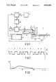
- FIG. 1shows an apparatus in accordance with the invention for manufacturing a record carrier
- FIG. 2shows a signal scanning spot position Ip generated in the apparatus shown in FIG. 1,
- FIG. 3shows the frequency spectrum of the scanning spot position signal Ip in FIG. 2,
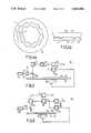
- FIGS. 4a and 4bshow a record carrier in accordance with the invention
- FIG. 5shows an apparatus in accordance with the invention for recording an information signal
- FIG. 6shows an apparatus in accordance with the invention for reading an information signal.
- FIG. 1shows an apparatus for manufacturing a record carrier in accordance with the invention.
- the apparatus 1comprises a turntable 2 which is rotated by a drive means 3.
- a disc-shaped record carrier 4 with a light-sensitive layer 5, for example in the form of a photoresist,can be placed on the turntable 2.
- a laser 6produces a light beam 7 which is projected on the light-sensitive layer 5.
- the light beam 7is first passed through a deflection device 10.
- the deflection device 10is of a type by means of which a light beam can be deflected very accurately within a narrow range.
- the apparatus described hereinsuitably employs an acousto-optical modulator as a deflection device.
- other beam deflection devicessuch as for example a mirror which is pivotable through a small angle.
- the dashed line in FIG. 1indicates the limits of the deflection range.
- the light beam 7 deflected by the beam deflection device 10is directed to an optical head 16 via a lens 15.
- the optical headcomprises a mirror 17 and an object lens 18 for focussing the light beam on the light-sensitive layer 5.
- the optical headis radially movable relative to the rotating carrier 4 by means of a translation device 19.
- the light beam 7is focussed into a scanning spot 20 on the light-sensitive layer 5, the position of this scanning spot 20 being determined by the degree of deflection of the light beam 7 caused by the beam deflection device 10 and the radial position of the optical head 16 relative to the carrier 4.
- the beam deflection device 10can deflect the scanning spot 20 within a range indicated by B1. This deflection range of the scanning spot can be moved over a larger range indicated by B2 by translation of the optical head 16.
- the apparatus 1comprises a voltage-controlled oscillator 30, which generates a control signal for the beam deflection device 10.
- a voltage-controlled oscillator 30may be an acousto-optical modulator of a customary type which deflects the light beam through an angle which is determined by the frequency of the control signal supplied by the voltage-controlled oscillator 30.
- An oscillator 31generates a signal of constant frequency fc.
- a frequency modulator 32the frequency fc of this signal is modulated with a position-information signal Ip generated by a control device 21.
- the control device 21further controls the speed of the drive means 3 and the speed of the translating device 19 in such a way that the radiation beam 7 scans the light-sensitive layer with a constant velocity along a spiral track. This control system falls beyond the scope of the present invention and is therefore not described in further detail.
- the position-information signal Ipis formed as a binary signal consisting of a sequence of bits having a logic value "1" or "0", which signal represents a sequence of digital time-information code words. These time-information code words indicate the time expired since the beginning of the scanning operation.
- An example of such a signal Ipis shown in FIG. 2b, a part of the time-information code words represented by the signal Ip being shown in FIG. 2a.
- the position-information signal Ipexhibits a "biphase" modulation.
- the applied code word digital signalis converted into a binary signal which is positive during the time interval T/2 for a logic "one" of the applied digital signal and which is negative during the next time interval T/2, T being the bit period of the applied digital signal.
- a logic "zero"results in the opposite binary signal, i.e. one which is negative during the time interval T/2 and positive during the next time interval T/2.
- This modulation techniqueyields a binary signal Ip having a power-distribution frequency spectrum as shown in FIG. 3.
- the frequency focorresponds to 1/T.
- FIG. 1By means of the apparatus shown in FIG. 1 the light-sensitive layer 5 is scanned along a spiral track. Moreover, the scanning spot 20 is moved to and fro over a small distance within the range B1 at a frequency corresponding to the frequency fc' of the output signal of the frequency modulator 32. As a result of this, the spiral track described by the scanning spot 20 on the light-sensitive layer 5 exhibits a radial undulation at a frequency which is modulated with the position-information signal Ip.
- the light-sensitive layer 5 thus scannedwhich layer consists of a photoresist, can subsequently be developed and subjected to a photo-etching process, yielding a master disc in which there is a spiral groove with a radial frequency-modulated undulation (wobble). Subsequently, replicas are made of this master disc, which replicas are provided with a radiation-sensitive information layer.
- FIGS. 4a and 4bshow a record carrier 40 in accordance with the invention, manufactured as described in the for
- FIG. 4ais a plan view of the record carrier 40.
- the record carrier 40exhibits a spiral track 41 with the radial wobble.
- the pitch of the spiral and the radial wobbleare strongly exaggerated.
- the pitch between the consecutive turns of the spiral trackis generally of the order of magnitude of 1 to 2 ⁇ m.
- the period of the radial wobbleis suitably such that during reading of an information signal recorded on the record carrier the frequency components produced in the read signal by the radial wobble are situated substantially outside the frequency spectrum of the information signal to be recorded and/or read.
- FIG. 4bis a sectional view I--I of the record carrier 40 comprising a substrate 42, a radiation sensitive information layer 43, and a transparent coating 44.
- FIG. 5shows an apparatus 50 in accordance with the invention for recording an information signal Vi on the record carrier 40.
- the apparatus 50comprises a drive means 52 for rotating the record carrier 40 which is placed on a turntable 51.
- a radiation source 53produces a radiation beam 54 for scanning the groove 41.
- the radiation beam 54is then directed towards the record carrier 40 via a modulation device 55 and a semitransparent mirror 56.
- the modulation device 55the intensity of the beam 54 can be modulated depending on an information signal Vi to be recorded, in such a way that an optically detectable information pattern is formed in the information layer 43 at the location of the groove 41.
- the modulated beam 54is then partly reflected by the information layer 43.
- the reflected beamis detected by means of a detection circuit 57.
- the detection circuit 57generates an output signal containing frequency components produced by the modulated radial wobble.
- This output signalis filtered by a band-pass filter 58 which mainly transmits the frequency components caused by the modulated radial wobble.
- the mean value of the instantaneous frequency fs of this output signalis employed as a measurement signal for controlling the velocity with which the record carrier is scanned by the beam 54 (scanning velocity).
- This output signal of the band-pass filter 58is applied to a control circuit 59 for generating a control signal for the drive means 52.
- the control circuit 59controls the speed of rotation of the record carrier 40 via the drive means 52 so as to maintain the mean value of the instantaneous frequency fs substantially equal to a reference frequency fref.
- the control loop thus formed for controlling the scanning velocity of the record carrierhas a limited bandwidth, so that rapid frequency variations of the instantaneous frequency fs caused by frequency components outside this limited bandwidth do not affect the control process.
- the frequency of the radial wobble in the apparatus 1 for manufacturing the record carrieris modulated with a position-information signal Ip which does not have any high power frequency components in the low-frequency range. If the frequency band used for scanning-velocity control and the frequency spectrum of the position-information signal are adapted to one another in such a way that hardly any frequency components of this frequency spectrum are situated within the velocity control frequency band, the applied FM modulation of the low frequency radial wobble will not affect the controlled scanning velocity.
- the position-information signal Ipis recovered from the output signal of the filter 58 by means of an FM demodulation circuit 60.
- This position-information signal Ipindicates the position of the scanned portion of the groove 42 relative to the beginning of the groove expressed in playing time.
- This position-information signal Ipmay be used inter alia for locating the track portion in which an information signal to be recorded is to be stored. Locating this portion falls beyond the scope of the present invention and is therefore not described in further detail.
- FIG. 6shows an apparatus 70 in accordance with the invention for reading the information signal Vi recorded on the record carrier 40, elements corresponding to elements of the apparatus 50 shown in FIG. 5 bearing the same reference numerals.
- the record carrier 40 on which the information signal Vi is recordedis scanned by a radiation beam 54a produced by a radiation source 53a.
- the intensity of the radiation beam 54ais too low to produce a change in the optical properties of the information layer 43, so that the information pattern already formed is not overwritten.
- the information pattern in the spiral groove with the radial wobblemodulates and subsequently reflects the radiation beam 54a.
- the reflected and modulated radiation beam 54ais detected by a detection device 57a.
- the detection device 57acomprises a first section having an increased sensitivity to the modulation of the light beam produced by the radial wobble and a second section having an increased sensitivity to the modulation produced by the information pattern.
- a detection deviceis described in detail in the aforementioned Offenlegungsschrift No. 3100421.
- the signal generated by the first section of the detection circuit 57ais applied to a filter 71 for removing frequency components produced by the radial wobble and by the velocity control, so that the information signal Vi becomes available on the output of the filter 71.
- the scanning velocityis controlled by means of a control circuit 59 and the position-information signal Ip is recovered by means of the FM demodulation circuit 71.
- the signal Ipmay be used, for example, for locating specific portions of the record carrier or for displaying the playing time during reading of the recorded information.
Landscapes
- Engineering & Computer Science (AREA)
- Manufacturing & Machinery (AREA)
- Optical Recording Or Reproduction (AREA)
Abstract
Description
This is a continuation of application Ser. No. 07/302,129, filed Jan. 24, 1989 now abandoned. This is a continuation of application Ser. No. 015,454, filed Feb. 17, 1987, now abandoned.
1. Field of the Invention
The invention relates to an optically readable record carrier comprising a radiation-sensitive layer upon a disc-shaped substrate and having an information recording area arranged in accordance with a spiral or concentric track pattern, which record carrier is intended for the recording and/or reproduction of information in the information recording area by means of a radiation beam, which track pattern exhibits a periodic modulation for the purpose of generating a clock signal for controlling the recording and/or reproducing process.
The invention further relates to an apparatus for manufacturing such a record carrier, comprising a writing device for writing the track pattern by means of a radiation beam and a control device for generating a periodic control signal for the writing device so as to modulate the track pattern at a frequency which corresponds to the frequency of the periodic control signal.
The invention further relates to an apparatus for recording information on such a record carrier, comprising means for scanning the tracks by means of a radiation beam, a modulation device for modulating the radiation beam intensity with an information signal, an optical system with a detector for detecting the radiation reflected or transmitted by the record carrier during scanning, and a device for deriving from the radiation detected by the detector a clock signal for controlling the recording apparatus.
The invention also relates to an apparatus for reading an information signal recorded on the information tracks of such a record carrier, comprising a scanning device for scanning the information tracks with a substantially constant velocity by means of a radiation beam, an optical system with a detector for detecting the radiation reflected or transmitted by the record carrier during scanning, a device for deriving from the detected radiation an information signal representing the recorded information, and a device for further deriving from the detected radiation a clock signal for controlling the reading apparatus.
2. Description of the Related Art
Such a record carrier and apparatus are described in German Offenlegungsschrift No. 3100421, which corresponds to pending U.S. application Ser. No. 110,063, assigned to the present assignee.
The known record carrier has a spiral track which exhibits a track modulation of constant frequency. As the spiral track is scanned by means of the radiation beam during reading and/or recording this track modulation produces a modulation of the reflected radiation beam. This modulation is detected and from the modulation thus detected a clock signal is derived which is utilized for controlling the recording and/or reading process.
Further, the spiral track is provided with information recording areas between which synchronisation areas are interposed. The information recording areas are intended for the recording of information. The synchronisation areas contain position information in the form of the address of the adjacent information recording area. The position information in the synchronization areas makes it possible to derive from the reflected radiation beam during scanning which part of the record carrier is being scanned. This enables a specific part of the disc to be located rapidly and accurately.
However, the known record carrier has the disadvantage that the information recording areas are constantly interrupted by synchronization areas. This is a drawback in particular when EFM-encoded information is to be recorded on the record carrier such because such recording of such information requires an uninterrupted information recording area. EFM-encoding is a method by which groups of 8 data bits at a time are translated into 14 channel bits for recording information on a compact digital disc. This is described, for example, in the article "Compact Disc: System Aspects and Modulation", Philips Tech. Rev. 40, No. 6, 1982.
It is an object of the invention to enable recording of EFM encoded signals and on an optical disc record carrier, to determine which part of the disc is being scanned by the light beam reflected from the record carrier.
In accordance with a first aspect of the invention a record carrier of the type defined in the opening paragraph is characterized in that the frequency of the track modulation is modulated with a digital position-information signal. In accordance with a second aspect of the invention an apparatus for manufacturing the record carrier is characterized in that such apparatus comprises frequency-modulation means for frequency-modulating the clock signal with a digital position-information signal. In accordance with a third aspect of the invention an apparatus for recording information on such a record carrier is characterized in that the recording apparatus comprises an FM demodulation device for recovering the digital position-information signal from the clock signal. In accordance with a fourth aspect of the invention an apparatus for reading information of the type defined in the foregoing is characterized in that the reading apparatus comprises an FM demodulation device for recovering the digital position-information signal from the clock signal. This enables the clock signal to be generated, the position of the part of the disc being scanned to be determined, and the recording or reading of the information signal to be recorded and/or read, all simultaneously during reading and/or recording.
In an embodiment of the record carrier the clock signal is utilized for controlling the velocity with which the tracks are scanned by the radiation beam during recording and/or reproduction. At the nominal scanning velocity of the tracks the frequency components produced in the modulation of the clock signal by the digital position-information signal are situated substantially outside the frequency band used for velocity control. As such frequency components caused by the track modulation are situated outside the frequency band used for velocity control, the presence of these frequency components does not disturb velocity control.
Embodiments of the invention and further advantages thereof will now be described in more detail, by way of example, with reference to FIGS. 1 to 6, in which
FIG. 1 shows an apparatus in accordance with the invention for manufacturing a record carrier,
FIG. 2 shows a signal scanning spot position Ip generated in the apparatus shown in FIG. 1,
FIG. 3 shows the frequency spectrum of the scanning spot position signal Ip in FIG. 2,
FIGS. 4a and 4b show a record carrier in accordance with the invention,
FIG. 5 shows an apparatus in accordance with the invention for recording an information signal,
FIG. 6 shows an apparatus in accordance with the invention for reading an information signal.
FIG. 1 shows an apparatus for manufacturing a record carrier in accordance with the invention. Theapparatus 1 comprises aturntable 2 which is rotated by adrive means 3. A disc-shaped record carrier 4 with a light-sensitive layer 5, for example in the form of a photoresist, can be placed on theturntable 2.
Alaser 6 produces a light beam 7 which is projected on the light-sensitive layer 5. The light beam 7 is first passed through adeflection device 10. Thedeflection device 10 is of a type by means of which a light beam can be deflected very accurately within a narrow range. The apparatus described herein suitably employs an acousto-optical modulator as a deflection device. However, it is alternatively possible to use other beam deflection devices, such as for example a mirror which is pivotable through a small angle. The dashed line in FIG. 1 indicates the limits of the deflection range. The light beam 7 deflected by thebeam deflection device 10 is directed to anoptical head 16 via alens 15. The optical head comprises amirror 17 and anobject lens 18 for focussing the light beam on the light-sensitive layer 5. The optical head is radially movable relative to the rotating carrier 4 by means of atranslation device 19.
By means of the optical system described above the light beam 7 is focussed into ascanning spot 20 on the light-sensitive layer 5, the position of thisscanning spot 20 being determined by the degree of deflection of the light beam 7 caused by thebeam deflection device 10 and the radial position of theoptical head 16 relative to the carrier 4. In the shown position of theoptical head 16 thebeam deflection device 10 can deflect thescanning spot 20 within a range indicated by B1. This deflection range of the scanning spot can be moved over a larger range indicated by B2 by translation of theoptical head 16.
Further theapparatus 1 comprises a voltage-controlledoscillator 30, which generates a control signal for thebeam deflection device 10. Such device may be an acousto-optical modulator of a customary type which deflects the light beam through an angle which is determined by the frequency of the control signal supplied by the voltage-controlledoscillator 30. Anoscillator 31 generates a signal of constant frequency fc. By means of afrequency modulator 32 the frequency fc of this signal is modulated with a position-information signal Ip generated by acontrol device 21. Thecontrol device 21 further controls the speed of the drive means 3 and the speed of the translatingdevice 19 in such a way that the radiation beam 7 scans the light-sensitive layer with a constant velocity along a spiral track. This control system falls beyond the scope of the present invention and is therefore not described in further detail.
The position-information signal Ip is formed as a binary signal consisting of a sequence of bits having a logic value "1" or "0", which signal represents a sequence of digital time-information code words. These time-information code words indicate the time expired since the beginning of the scanning operation. An example of such a signal Ip is shown in FIG. 2b, a part of the time-information code words represented by the signal Ip being shown in FIG. 2a. The position-information signal Ip exhibits a "biphase" modulation. The applied code word digital signal is converted into a binary signal which is positive during the time interval T/2 for a logic "one" of the applied digital signal and which is negative during the next time interval T/2, T being the bit period of the applied digital signal. A logic "zero" results in the opposite binary signal, i.e. one which is negative during the time interval T/2 and positive during the next time interval T/2. This modulation technique yields a binary signal Ip having a power-distribution frequency spectrum as shown in FIG. 3. Here the frequency fo corresponds to 1/T.
As is apparent from FIG. 3, such a "biphase" modulated signal does not have high power frequency components in the low-frequency range. The advantages of this will be described comprehensively hereinafter.
By means of the apparatus shown in FIG. 1 the light-sensitive layer 5 is scanned along a spiral track. Moreover, thescanning spot 20 is moved to and fro over a small distance within the range B1 at a frequency corresponding to the frequency fc' of the output signal of thefrequency modulator 32. As a result of this, the spiral track described by thescanning spot 20 on the light-sensitive layer 5 exhibits a radial undulation at a frequency which is modulated with the position-information signal Ip. The light-sensitive layer 5 thus scanned, which layer consists of a photoresist, can subsequently be developed and subjected to a photo-etching process, yielding a master disc in which there is a spiral groove with a radial frequency-modulated undulation (wobble). Subsequently, replicas are made of this master disc, which replicas are provided with a radiation-sensitive information layer. FIGS. 4a and 4b show arecord carrier 40 in accordance with the invention, manufactured as described in the foregoing.
FIG. 4a is a plan view of therecord carrier 40. Therecord carrier 40 exhibits aspiral track 41 with the radial wobble. For the sake of clarity the pitch of the spiral and the radial wobble are strongly exaggerated. In reality, the pitch between the consecutive turns of the spiral track is generally of the order of magnitude of 1 to 2 μm. In practice the period of the radial wobble is suitably such that during reading of an information signal recorded on the record carrier the frequency components produced in the read signal by the radial wobble are situated substantially outside the frequency spectrum of the information signal to be recorded and/or read. If an EFM encoded signal in conformity with the customary "Compact Disc" standard is recorded, a radial wobble causing frequency components near 22 kHz in the read signal with a frequency excursion of 1.5 kHz proves to be adequate. The recorded EFM encoded signal and the radial wobble then hardly influence one another.
FIG. 4b is a sectional view I--I of therecord carrier 40 comprising asubstrate 42, a radiationsensitive information layer 43, and atransparent coating 44.
FIG. 5 shows anapparatus 50 in accordance with the invention for recording an information signal Vi on therecord carrier 40. Theapparatus 50 comprises a drive means 52 for rotating therecord carrier 40 which is placed on aturntable 51. Aradiation source 53 produces aradiation beam 54 for scanning thegroove 41. Theradiation beam 54 is then directed towards therecord carrier 40 via amodulation device 55 and asemitransparent mirror 56. By means of themodulation device 55 the intensity of thebeam 54 can be modulated depending on an information signal Vi to be recorded, in such a way that an optically detectable information pattern is formed in theinformation layer 43 at the location of thegroove 41. The modulatedbeam 54 is then partly reflected by theinformation layer 43. The reflected beam is detected by means of adetection circuit 57. Thedetection circuit 57 generates an output signal containing frequency components produced by the modulated radial wobble. This output signal is filtered by a band-pass filter 58 which mainly transmits the frequency components caused by the modulated radial wobble. The mean value of the instantaneous frequency fs of this output signal is employed as a measurement signal for controlling the velocity with which the record carrier is scanned by the beam 54 (scanning velocity). This output signal of the band-pass filter 58 is applied to acontrol circuit 59 for generating a control signal for the drive means 52. Thecontrol circuit 59 controls the speed of rotation of therecord carrier 40 via the drive means 52 so as to maintain the mean value of the instantaneous frequency fs substantially equal to a reference frequency fref. The control loop thus formed for controlling the scanning velocity of the record carrier has a limited bandwidth, so that rapid frequency variations of the instantaneous frequency fs caused by frequency components outside this limited bandwidth do not affect the control process. As already described, the frequency of the radial wobble in theapparatus 1 for manufacturing the record carrier is modulated with a position-information signal Ip which does not have any high power frequency components in the low-frequency range. If the frequency band used for scanning-velocity control and the frequency spectrum of the position-information signal are adapted to one another in such a way that hardly any frequency components of this frequency spectrum are situated within the velocity control frequency band, the applied FM modulation of the low frequency radial wobble will not affect the controlled scanning velocity.
Satisfactory results in recording EFM encoded signals in conformity with the compact disc standard have been obtained for an fref of approximately 22 kHz, a bit frquency of the position-information signal of approximately 3000 bits/second, and a velocity-control clock signal bandwidth of approximately 100 Hz.
The position-information signal Ip is recovered from the output signal of thefilter 58 by means of anFM demodulation circuit 60. This position-information signal Ip indicates the position of the scanned portion of thegroove 42 relative to the beginning of the groove expressed in playing time. This position-information signal Ip may be used inter alia for locating the track portion in which an information signal to be recorded is to be stored. Locating this portion falls beyond the scope of the present invention and is therefore not described in further detail.
FIG. 6 shows anapparatus 70 in accordance with the invention for reading the information signal Vi recorded on therecord carrier 40, elements corresponding to elements of theapparatus 50 shown in FIG. 5 bearing the same reference numerals. In theapparatus 70 therecord carrier 40 on which the information signal Vi is recorded is scanned by aradiation beam 54a produced by aradiation source 53a. The intensity of theradiation beam 54a is too low to produce a change in the optical properties of theinformation layer 43, so that the information pattern already formed is not overwritten. The information pattern in the spiral groove with the radial wobble modulates and subsequently reflects theradiation beam 54a. The reflected and modulatedradiation beam 54a is detected by adetection device 57a. Thedetection device 57a comprises a first section having an increased sensitivity to the modulation of the light beam produced by the radial wobble and a second section having an increased sensitivity to the modulation produced by the information pattern. Such a detection device is described in detail in the aforementioned Offenlegungsschrift No. 3100421. The signal generated by the first section of thedetection circuit 57a is applied to afilter 71 for removing frequency components produced by the radial wobble and by the velocity control, so that the information signal Vi becomes available on the output of thefilter 71. In the same way as described with reference to FIG. 5 the scanning velocity is controlled by means of acontrol circuit 59 and the position-information signal Ip is recovered by means of theFM demodulation circuit 71. Subsequently, the signal Ip may be used, for example, for locating specific portions of the record carrier or for displaying the playing time during reading of the recorded information.
In the foregoing the apparatus for recording information and the apparatus for reading the recorded information have been described as two separate apparatuses. It will obvious to those skilled in the art that the two apparatuses may be readily combined to form a single apparatus both for recording and reading.
In the foregoing a track modulation in the form of a radial wobble has been provided for the purpose of scanning-velocity control in the reading and recording apparatus. It will be evident that other track modulations are also suitable for this purpose, for example those as described in German Offenlegungsschrift No. 3100278 and No. 3100421. In order to obtain a suitable track modulation care must be taken only that the scanning-beam modulation produced by the track modulation can be distinguished from the scanning-beam modulation caused by the information signal Vi and that the frequency componets of these scanning-beam modulations are situated substantially outside the frequency band used for scanning-velocity control.
Claims (10)
1. An optical disc record carrier having a radiation-sensitive surface for recording information in a pattern of spiral or concentric tracks thereon, which information may be recorded or read by scanning such tracks with a radiation beam which produces radiation therefrom; characterized in that each of said tracks has a periodic modulation of its position in a direction transverse thereto and which, without occupying any portion of the track, generates a periodic clock signal in the radiation therefrom having a substantially constant frequency corresponding to the velocity of scanning of said tracks, the frequency of said clock signal only varying in accordance with variations in said scanning velocity; and in that the frequency of said clock signal is modulated in accordance with a digital position signal which identifies the relative positions of said tracks on said record carrier; whereby said scanning velocity and the relative positions of said tracks are both recorded without occupying any portion of said tracks.
2. A record carrier as claimed in claim 1, wherein the frequency components of the modulation of said clock signal which are produced by the digital position signal are substantially outside the frequency band of the variations in the frequency of said clock signal caused by variations in said scanning velocity.
3. A record carrier as claimed in either of claims 1 and 2, wherein the digital position signal which is generated at any position in said track pattern indicates the time from the beginning of said track pattern to such track position when scanning is effected at a velocity corresponding to the frequency of said clock signal.
4. A record carrier as claimed in either of claims 1 and 2, wherein said track modulation is in the form of a periodic wobble in the radial displacement of each of said tracks, the frequency of such wobble being modulated by said digital position signal.
5. Apparatus for manufacturing an optical disc record carrier having a radiation sensitive surface for recording information in a pattern of spiral or concentric tracks thereon, comprising:
means for scanning a radiation beam across the surface of said record carrier to form said track pattern thereon;
means for generating a periodic control signal for said scanning means which modulates the position of each of said tracks in a direction transverse thereto at a substantially constant frequency corresponding to the velocity of scanning of said tracks, wherein the mean frequency of said control signal only varying in accordance with variations in said scanning velocity; and
means for modulating the frequency of said control signal with a digital position signal which identifies the relative positions of each of said tracks on said record carrier;
whereby said scanning velocity and the relative positions of said tracks are both recorded without occupying any portion of said tracks.
6. An apparatus as claimed in claim 5, wherein the digital position signal for any track signifies the time for said radiation beam to scan from the beginning of said track pattern to such track when such scanning is effected at a substantially constant velocity corresponding to the mean frequency of said modulated control signal.
7. Apparatus for recording information on an optical disc record carrier having a radiation-sensitive surface patterned in spiral or concentric tracks thereon which when scanned by a radiation beam produce radiation therefrom; the position of each of said tracks in a direction transverse thereto having a periodic modulation which, without occupying any portion of the track, generates a periodic clock signal in the radiation produced therefrom, such clock signal having a substantially constant frequency corresponding to the velocity of scanning of said tracks, which frequency is modulated by a digital position signal identifying the relative positions of said tracks on said record carrier, wherein the mean frequency of said clock signal only varying in accordance with variations in said scanning velocity; such apparatus comprising:
means for producing a radiation beam which is scanned across said track pattern to record information thereon and produce radiation therefrom;
optical means for detecting the radiation produced from said tracks;
means for deriving from the radiation detected by said optical means the frequency modulated periodic clock signal generated by said tracks during scanning thereof;
means for deriving from said frequency modulated clock signal a speed control signal for controlling said scanning velocity; and
frequency demodulation means for demodulating said frequency modulated periodic clock signal to recover therefrom said digital position signal.
8. Apparatus as claimed in claim 7, further comprising means for controlling said radiation beam to scan said track pattern at a substantially constant velocity corresponding to the mean frequency of said frequency modulated periodic clock signal.
9. Apparatus for reading information recorded on an optical disc record carrier having a radiation-sensitive surface patterned in spiral or concentric tracks thereon which when scanned by a radiation beam produce radiation therefrom, the position of each of said tracks in a direction transverse thereto having a periodic modulation which, without occupying any portion of a track, constitutes a frequency modulated periodic clock signal having a substantially constant frequency corresponding to the velocity of scanning of said tracks, the frequency modulation thereof being a digital position signal which identifies the relative positions of said tracks on said record carrier, wherein the frequency of said clock signal only varies in accordance with variations in said scanning velocity; the radiation from said tracks also including an information signal corresponding to information recorded on said tracks; such apparatus comprising:
means for scanning a radiation beam across said track pattern to produce radiation therefrom;
optical means for detecting the radiation so produced;
means for deriving said information signal from the radiation detected by said optical means;
means for further deriving said frequency modulated clock signal from the radiation detected by said optical means;
means for deriving from said frequency modulated clock signal from the radiation detected by said optical means;
means for deriving from said frequency modulated clock signal a speed control signal corresponding to the mean frequency thereof for controlling the scanning velocity; and
means for frequency demodulating said frequency modulated clock signal to recover therefrom said digital position signal.
10. Apparatus as claimed in claim 9, further comprising means for controlling said radiation beam to scan said track pattern at a substantially constant velocity corresponding to the mean frequency of said frequency modulated periodic clock signal.
Applications Claiming Priority (2)
| Application Number | Priority Date | Filing Date | Title |
|---|---|---|---|
| NL8602504 | 1986-10-06 | ||
| NL8602504ANL8602504A (en) | 1986-10-06 | 1986-10-06 | OPTICALLY READABLE RECORD CARRIAGE FOR RECORDING INFORMATION, AN APPARATUS FOR MANUFACTURING SUCH RECORD CARRIER, AN APPARATUS FOR RECORDING INFORMATION ON SUCH RECORD CARRIERS AND AN ESTABLISHMENT DEVICE FOR RECORDS. |
Related Parent Applications (1)
| Application Number | Title | Priority Date | Filing Date |
|---|---|---|---|
| US07302129Continuation | 1989-01-24 |
Publications (1)
| Publication Number | Publication Date |
|---|---|
| US5023856Atrue US5023856A (en) | 1991-06-11 |
Family
ID=19848634
Family Applications (1)
| Application Number | Title | Priority Date | Filing Date |
|---|---|---|---|
| US07/501,342Expired - LifetimeUS5023856A (en) | 1986-10-06 | 1990-03-28 | Optically readable record carrier for recording information, apparatus for manufacturing such a record carrier, apparatus for recording information on such a record carrier, and apparatus for reading information recorded on such a record carrier |
Country Status (2)
| Country | Link |
|---|---|
| US (1) | US5023856A (en) |
| NL (1) | NL8602504A (en) |
Cited By (87)
| Publication number | Priority date | Publication date | Assignee | Title |
|---|---|---|---|---|
| US5163035A (en)* | 1989-04-28 | 1992-11-10 | Kabushiki Kaisha Kenwood | Constant linear velocity recording servo circuit for write-once type compact disk |
| US5166913A (en)* | 1988-01-27 | 1992-11-24 | Nec Corporation | Optical disk device for record and reproduction of additional information besides reproducing of basic information |
| US5177727A (en)* | 1989-04-27 | 1993-01-05 | Teac Corporation | Rotary recording medium having a guide track and recording and reproducing apparatus therefor |
| US5265076A (en)* | 1991-01-31 | 1993-11-23 | Kabushiki Kaisha Toshiba | Image retrieval apparatus using combination retrieval items |
| US5268887A (en)* | 1990-05-15 | 1993-12-07 | Kabushiki Kaisha Toshiba | Optical recording medium having offset-compensating areas |
| US5270998A (en)* | 1990-11-06 | 1993-12-14 | Pioneer Electronic Corporation | Rewritable recording medium and recording reproducing apparatus for use with rewritable recording medium |
| US5383070A (en)* | 1990-11-21 | 1995-01-17 | Bond; Charles R. | Method and device for measuring disk drive alignment |
| US5418764A (en)* | 1988-01-22 | 1995-05-23 | U.S. Philips Corporation | Recording device, a record carrier having preformatted address codes and auxiliary codes providing control data for use by the recording device, and an information recording system including both the recording device and the record carrier |
| US5463614A (en)* | 1992-09-21 | 1995-10-31 | Nikon Corporation | Optical recording medium having large guide groove track pitch/meander amplitude ratio |
| US5537373A (en)* | 1993-06-25 | 1996-07-16 | Kabushiki Kaisha Kenwood | Optical disk recording and reproducing apparatus with data recorded on wobbled grooves and lands |
| US5546365A (en)* | 1988-06-15 | 1996-08-13 | U.S. Philips Corporation | Record carriers containing a user's preferred order of reproduction of items of information included therein, and apparatus for use with and/or for creating such record carriers |
| US5631892A (en)* | 1992-05-06 | 1997-05-20 | Bakx; Johannes L. | Optical storage disc scanner with improved scanner positioning |
| US5696755A (en)* | 1992-11-04 | 1997-12-09 | Storage Technology Corporation | System for minimizing the effects of scratches on recording media |
| US5757756A (en)* | 1996-10-15 | 1998-05-26 | Eastman Kodak Company | Reducing mark length variations in recording data in wobbled groove storage media |
| US5835478A (en)* | 1995-06-15 | 1998-11-10 | Sony Corporation | Optical disc having address information for recording and reproducing data at correct positions |
| US5844882A (en)* | 1996-03-25 | 1998-12-01 | Sony Corporation | Recording medium, address recording method and apparatus, and recording/reproducing method and apparatus for reducing crosstalk of addressing signals |
| US5930228A (en)* | 1996-07-26 | 1999-07-27 | Hitachi, Ltd. | Method and apparatus for recording and reproducing information using pseudo identification signal |
| US6009059A (en)* | 1996-08-27 | 1999-12-28 | Mitsumi Electric Co., Ltd. | Method for generating a wobble signal in a CD-R drive |
| US6028828A (en)* | 1996-08-30 | 2000-02-22 | Sharp Kabushiki Kaisha | Disk type recording medium and disk recording and reproducing device |
| US6046968A (en)* | 1997-07-24 | 2000-04-04 | Hewlett-Packard Company | Re-writable optical disk having reference clock information permanently formed on the disk |
| US6052358A (en)* | 1996-10-04 | 2000-04-18 | Sony Corporation | Head feeding mechanism and optical pick-up feeding mechanism |
| US6091681A (en)* | 1996-09-03 | 2000-07-18 | U.S. Philips Corporation | Information carrier, reading/writing device and reading device for writing and/or reading information blocks |
| EP0902947A4 (en)* | 1996-05-31 | 2001-02-28 | Cagent Technologies Inc | OPTICAL DISC HAVING SOFTWARE ANTI-HACKING |
| US6269071B1 (en) | 1998-03-16 | 2001-07-31 | U.S. Philips Corporation | Optical record carrier |
| US6353582B1 (en) | 1998-12-15 | 2002-03-05 | Pioneer Corporation | Pickup device |
| US6411585B1 (en)* | 1997-05-19 | 2002-06-25 | Sony Corporation | Method for manufacturing optical disk, optical disk apparatus, and optical disk with using phase-shifted signal for wobbling grooves |
| US20020114230A1 (en)* | 2001-01-25 | 2002-08-22 | Kadlec Ron J. | Tracking and focus servo system with error signal inverse non-linearity calibration |
| US20020118614A1 (en)* | 2001-01-25 | 2002-08-29 | Watt Charles R. | Detector input dark current offset calibration in an optical disk drive |
| US20020131342A1 (en)* | 2001-01-25 | 2002-09-19 | Dataplay, Inc. | Digital servo system with calibrated notch filters |
| US20020136114A1 (en)* | 2001-01-25 | 2002-09-26 | Kadlec Ron J. | Digital focus and tracking servo system with multi-zone calibration |
| US20020136112A1 (en)* | 2001-01-25 | 2002-09-26 | Dataplay, Inc. | Calibration of tracking error signal offset in a tracking servo system |
| US20020136129A1 (en)* | 2001-01-25 | 2002-09-26 | Kadlec Ron J. | Focus detection in a digital focus servo system |
| US20020136110A1 (en)* | 2001-01-25 | 2002-09-26 | Watt Charles R. | Tracking and focus servo system with automatic media type detector |
| US20020136113A1 (en)* | 2001-01-25 | 2002-09-26 | Dataplay, Inc. | Digital servo system with biased feed-forward |
| US20020136115A1 (en)* | 2001-01-25 | 2002-09-26 | Dataplay, Inc. | Calibration initiation methods for a tracking and focus servo system |
| US20020136116A1 (en)* | 2001-01-25 | 2002-09-26 | Kadlec Ron J. | Digital servo system with inverse non-linearity compensation |
| US20020141298A1 (en)* | 2001-01-25 | 2002-10-03 | Kadlec Ron J. | Digital tracking servo system with multi-track seek with track zero crossing detection |
| US20020141309A1 (en)* | 2001-01-25 | 2002-10-03 | Kadlec Ron J. | Tracking and focus servo system with write abort |
| US20020141302A1 (en)* | 2001-01-25 | 2002-10-03 | Kadlec Ron J. | Digital tracking and focus servo system with TES to FES crosstalk calibration |
| US20020145953A1 (en)* | 2001-01-25 | 2002-10-10 | Kadlec Ron J. | Calibration of focus error signal offset in a focus servo system |
| US20020150006A1 (en)* | 2001-01-25 | 2002-10-17 | Kadlec Ron J. | Digital servo system with second order compensator |
| US20020150004A1 (en)* | 2001-01-25 | 2002-10-17 | Kadlec Ron J. | Digital tracking servo system with tracking skate detection |
| US20020167876A1 (en)* | 2001-01-25 | 2002-11-14 | Dataplay, Inc. | Digital servo system with error signal integrity testing |
| US6510015B2 (en) | 1999-12-10 | 2003-01-21 | Seagate Technology Llc | Magnetic disc having physical servo patterns with a magnetic carrier, and method of making and using the same |
| US20030031100A1 (en)* | 2001-01-25 | 2003-02-13 | Dataplay, Inc. | Digital servo system with loop gain calibration |
| US6538982B1 (en)* | 1999-01-25 | 2003-03-25 | Koninklijke Philips Electronics | Record carrier and apparatus for scanning the record carrier |
| US20030090825A1 (en)* | 2001-10-15 | 2003-05-15 | Schep Cornelis Marinus | Record carrier and apparatus for scanning the record carrier |
| US20030157292A1 (en)* | 1999-06-23 | 2003-08-21 | Dataplay, Inc. | Miniature optical disk for data storage |
| US6618346B1 (en) | 1999-01-29 | 2003-09-09 | Pioneer Corporation | Optical pickup device having aperture restriction arrangement |
| US6621772B2 (en) | 1996-09-26 | 2003-09-16 | Sanyo Electric Co., Ltd. | Record medium and reproducing apparatus of the same for detecting an offset correction |
| RU2219595C2 (en)* | 1996-07-01 | 2003-12-20 | Сони Корпорейшн | Optical recording medium, recording/reproducing method for recording medium, and device for recording/reproducing from recording medium |
| US20040001408A1 (en)* | 2000-05-30 | 2004-01-01 | Dataplay, Inc. | Defect management system for write-once storage disk |
| US6704261B2 (en) | 2001-01-25 | 2004-03-09 | Dphi Acquisitions, Inc. | Spin motor control in an optical drive |
| US6728182B2 (en) | 2001-01-25 | 2004-04-27 | Dphi Acquisitions, Inc. | Tracking and focus servo system with a media type boundary crossing detector |
| US20040090892A1 (en)* | 2001-01-25 | 2004-05-13 | Kadlec Ron J. | Tracking and focus servo system with defect detection |
| US6738333B1 (en) | 2000-05-30 | 2004-05-18 | Dphi Acquisitions, Inc. | Format for recording data in a storage disk |
| US6738320B2 (en) | 2001-01-25 | 2004-05-18 | Dphi Acquisitions, Inc. | System and method for moving optical pick up from current position to target position with smooth control |
| US6762980B2 (en) | 2001-01-25 | 2004-07-13 | Dphi Acquisitions, Inc. | Digital tracking servo system with a multi-track seeking and accelerated servo function for regaining a closed tracking loop |
| US6781929B2 (en) | 2001-01-25 | 2004-08-24 | Dphi Acquisitions, Inc. | Digital tracking servo system with multi-track seek |
| US6809995B2 (en) | 2001-01-25 | 2004-10-26 | Dphi Acquisitions, Inc. | Digital focus and tracking servo system |
| US6813226B2 (en) | 2001-01-25 | 2004-11-02 | Dphi Acquisitions, Inc. | Calibration of a focus sum threshold in a focus servo system |
| US6813228B2 (en) | 2001-01-25 | 2004-11-02 | Dphi Acquisitions, Inc. | Tracking and focus servo system with direction sensor |
| US6847596B2 (en) | 2001-01-25 | 2005-01-25 | Dphi Acquisitions, Inc. | Tracking servo system including a multi-track seek algorithm with a track zero crossing period integrity test |
| US6847597B2 (en) | 2001-01-25 | 2005-01-25 | Dphi Acquisitions, Inc. | Optical disk drive with a digital focus and tracking servo system |
| US20050068874A1 (en)* | 2002-01-22 | 2005-03-31 | Jacobus Petrus Josephus Heemskerk | Record carrier |
| US6882601B2 (en) | 2001-01-25 | 2005-04-19 | Dphi Acquisitions, Inc. | Digital servo system with feed-forward control loops |
| US6885619B2 (en) | 2001-01-25 | 2005-04-26 | Dphi Acquisitions, Inc. | Detector input stray light offset calibration in an optical disk drive |
| US6898164B2 (en) | 2001-01-25 | 2005-05-24 | Dphi Acquisitions, Inc. | Close tracking algorithm in a digital tracking servo system |
| US6906985B2 (en) | 2001-01-25 | 2005-06-14 | Dphi Acquisitions, Inc. | Calibration of tracking error signal gain in a tracking servo system |
| US6922380B2 (en) | 2001-01-25 | 2005-07-26 | Dphi Acquisitions, Inc. | Tracking and focus servo system with anti-skate algorithm |
| US6930963B2 (en) | 2001-01-25 | 2005-08-16 | Dphi Acquistions, Inc. | Tracking and focus servo system with head load |
| US6937543B2 (en) | 2001-01-25 | 2005-08-30 | Dphi Acquisitions, Inc. | Digital focus servo system with a sliding notch filter |
| US20050190686A1 (en)* | 2004-03-01 | 2005-09-01 | Wu-Hsuan Ho | Recordable optical disc and method for manufacturing a mother disc thereof |
| US6990058B1 (en) | 2000-04-03 | 2006-01-24 | Dphi Acquisitions, Inc. | Structure and method for storing data on optical disks |
| US7023766B2 (en) | 2001-01-25 | 2006-04-04 | Dphi Acquisitions, Inc. | Flexible servicing of servo algorithms using a digital signal processor |
| US20060077798A1 (en)* | 2004-09-30 | 2006-04-13 | Kabushiki Kaisha Toshiba | Optical disk apparatus and photodetection signal processing method |
| US7051054B1 (en) | 2000-05-30 | 2006-05-23 | Dphi Acquisitions, Inc. | Method and apparatus for emulating read/write file system on a write-once storage disk |
| US7196979B2 (en) | 2001-01-25 | 2007-03-27 | Dphi Acquisitions, Inc. | Calibration storage methods for a digital focus and tracking servo system with calibration |
| US7260031B2 (en) | 2001-01-25 | 2007-08-21 | Dphi Acquisitions, Inc. | Digital focus and tracking servo system with one-track jump |
| US20080170489A1 (en)* | 2007-01-11 | 2008-07-17 | Industrial Technology Research Institute | Optical recording carrier, signal generating apparatus, information recording method, and information reading apparatus |
| US7414940B2 (en) | 2001-01-25 | 2008-08-19 | Dphi Acquisitions, Inc. | Calibration of a focus error signal gain in a focus servo system |
| US20080233520A1 (en)* | 2000-10-03 | 2008-09-25 | Matsushita Electric Industrial Co., Ltd. | Method For Producing Multi-Layer Optical Disk |
| US7522480B2 (en) | 2001-01-25 | 2009-04-21 | Dphi Acquisitions, Inc. | Digital tracking servo system with multi-track seek with an acceleration clamp |
| US7593300B2 (en) | 2001-01-25 | 2009-09-22 | Dphi Acquisitions, Inc. | Digital tracking servo system with off-format detection |
| US20100034074A1 (en)* | 2006-11-30 | 2010-02-11 | Mitsubishi Kagaku Media Co., Ltd. | Information recording medium and master exposing apparatus |
| US7672199B2 (en) | 2001-01-25 | 2010-03-02 | Dphi Acquisitions, Inc. | Close focus algorithm in a digital focus servo system |
| US20100182893A1 (en)* | 1997-07-24 | 2010-07-22 | Abramovitch Daniel Y | Re-writable optical disk having reference clock information permanently formed on the disk |
Citations (11)
| Publication number | Priority date | Publication date | Assignee | Title |
|---|---|---|---|---|
| US3963862A (en)* | 1974-09-25 | 1976-06-15 | U.S. Philips Corporation | Record carrier for a television signal |
| US4067044A (en)* | 1975-02-05 | 1978-01-03 | Hitachi, Ltd. | Information recording and retrieval apparatus |
| JPS5468610A (en)* | 1977-11-12 | 1979-06-01 | Victor Co Of Japan Ltd | Recording and reproducing system of address signal in disc- shaped recording medium having spiral recording track |
| GB2022875A (en)* | 1978-06-09 | 1979-12-19 | Hitachi Ltd | Method and apparatus for recording and reproducing information |
| US4238843A (en)* | 1978-11-06 | 1980-12-09 | U.S. Philips Corporation | Disc-shaped optically readable record carrier used as a data storage medium |
| GB2069219A (en)* | 1980-01-09 | 1981-08-19 | Philips Nv | Optically readable digital information disc and manufacturing, recording and reading apparatus therefore |
| US4363116A (en)* | 1978-03-16 | 1982-12-07 | U.S. Philips Corporation | Method, apparatus and record carrier body for optically writing information |
| US4366564A (en)* | 1980-01-09 | 1982-12-28 | U.S. Philips Corporation | Apparatus for writing digital information in a disc-shaped optically readable record carrier |
| JPS595449A (en)* | 1982-06-30 | 1984-01-12 | Matsushita Electric Ind Co Ltd | Recording carrier for optical disk |
| JPS6063733A (en)* | 1984-08-20 | 1985-04-12 | Hitachi Ltd | Method and device for recording information |
| US4716560A (en)* | 1984-05-22 | 1987-12-29 | Victor Company Of Japan, Ltd. | Recording disc and method for fabricating same |
- 1986
- 1986-10-06NLNL8602504Apatent/NL8602504A/ennot_activeApplication Discontinuation
- 1990
- 1990-03-28USUS07/501,342patent/US5023856A/ennot_activeExpired - Lifetime
Patent Citations (11)
| Publication number | Priority date | Publication date | Assignee | Title |
|---|---|---|---|---|
| US3963862A (en)* | 1974-09-25 | 1976-06-15 | U.S. Philips Corporation | Record carrier for a television signal |
| US4067044A (en)* | 1975-02-05 | 1978-01-03 | Hitachi, Ltd. | Information recording and retrieval apparatus |
| JPS5468610A (en)* | 1977-11-12 | 1979-06-01 | Victor Co Of Japan Ltd | Recording and reproducing system of address signal in disc- shaped recording medium having spiral recording track |
| US4363116A (en)* | 1978-03-16 | 1982-12-07 | U.S. Philips Corporation | Method, apparatus and record carrier body for optically writing information |
| GB2022875A (en)* | 1978-06-09 | 1979-12-19 | Hitachi Ltd | Method and apparatus for recording and reproducing information |
| US4238843A (en)* | 1978-11-06 | 1980-12-09 | U.S. Philips Corporation | Disc-shaped optically readable record carrier used as a data storage medium |
| GB2069219A (en)* | 1980-01-09 | 1981-08-19 | Philips Nv | Optically readable digital information disc and manufacturing, recording and reading apparatus therefore |
| US4366564A (en)* | 1980-01-09 | 1982-12-28 | U.S. Philips Corporation | Apparatus for writing digital information in a disc-shaped optically readable record carrier |
| JPS595449A (en)* | 1982-06-30 | 1984-01-12 | Matsushita Electric Ind Co Ltd | Recording carrier for optical disk |
| US4716560A (en)* | 1984-05-22 | 1987-12-29 | Victor Company Of Japan, Ltd. | Recording disc and method for fabricating same |
| JPS6063733A (en)* | 1984-08-20 | 1985-04-12 | Hitachi Ltd | Method and device for recording information |
Non-Patent Citations (2)
| Title |
|---|
| "Philips Technical Review", vol. 40, No. 6, 1982, pp. 151 to 179. |
| Philips Technical Review , vol. 40, No. 6, 1982, pp. 151 to 179.* |
Cited By (168)
| Publication number | Priority date | Publication date | Assignee | Title |
|---|---|---|---|---|
| US5654947A (en)* | 1988-01-22 | 1997-08-05 | U.S. Philips Corporation | Method for recording information on a record carrier having a track which is transversely modulated in accordance with an auxiliary signal including address codes and auxiliary codes, and a method for producing the track |
| US5418764A (en)* | 1988-01-22 | 1995-05-23 | U.S. Philips Corporation | Recording device, a record carrier having preformatted address codes and auxiliary codes providing control data for use by the recording device, and an information recording system including both the recording device and the record carrier |
| US5166913A (en)* | 1988-01-27 | 1992-11-24 | Nec Corporation | Optical disk device for record and reproduction of additional information besides reproducing of basic information |
| US5287335A (en)* | 1988-01-27 | 1994-02-15 | Nec Corporation | Optical disk device for record and reproduction of additional information besides reproduction of basic one |
| US5546365A (en)* | 1988-06-15 | 1996-08-13 | U.S. Philips Corporation | Record carriers containing a user's preferred order of reproduction of items of information included therein, and apparatus for use with and/or for creating such record carriers |
| US5177727A (en)* | 1989-04-27 | 1993-01-05 | Teac Corporation | Rotary recording medium having a guide track and recording and reproducing apparatus therefor |
| US5163035A (en)* | 1989-04-28 | 1992-11-10 | Kabushiki Kaisha Kenwood | Constant linear velocity recording servo circuit for write-once type compact disk |
| US5268887A (en)* | 1990-05-15 | 1993-12-07 | Kabushiki Kaisha Toshiba | Optical recording medium having offset-compensating areas |
| US5270998A (en)* | 1990-11-06 | 1993-12-14 | Pioneer Electronic Corporation | Rewritable recording medium and recording reproducing apparatus for use with rewritable recording medium |
| US5383070A (en)* | 1990-11-21 | 1995-01-17 | Bond; Charles R. | Method and device for measuring disk drive alignment |
| US5265076A (en)* | 1991-01-31 | 1993-11-23 | Kabushiki Kaisha Toshiba | Image retrieval apparatus using combination retrieval items |
| US5631892A (en)* | 1992-05-06 | 1997-05-20 | Bakx; Johannes L. | Optical storage disc scanner with improved scanner positioning |
| US5463614A (en)* | 1992-09-21 | 1995-10-31 | Nikon Corporation | Optical recording medium having large guide groove track pitch/meander amplitude ratio |
| US5696755A (en)* | 1992-11-04 | 1997-12-09 | Storage Technology Corporation | System for minimizing the effects of scratches on recording media |
| US5615185A (en)* | 1993-06-25 | 1997-03-25 | Kabushiki Kaisha Kenwood | Optical disk recording and reproducing apparatus with data recorded and reproducing apparatus with data recorded on wobbled grooves and lands |
| US5537373A (en)* | 1993-06-25 | 1996-07-16 | Kabushiki Kaisha Kenwood | Optical disk recording and reproducing apparatus with data recorded on wobbled grooves and lands |
| US5835478A (en)* | 1995-06-15 | 1998-11-10 | Sony Corporation | Optical disc having address information for recording and reproducing data at correct positions |
| US5835461A (en)* | 1995-06-15 | 1998-11-10 | Sony Corporation | Optical disc, apparatus and method for recording and reproducing data |
| US5878024A (en)* | 1995-06-15 | 1999-03-02 | Sony Corporation | Optical disc, apparatus and method for recording and reproducing data |
| US5886985A (en)* | 1995-06-15 | 1999-03-23 | Sony Corporation | Optical recording medium having a plurality of sectors separated by sync signals |
| US5844882A (en)* | 1996-03-25 | 1998-12-01 | Sony Corporation | Recording medium, address recording method and apparatus, and recording/reproducing method and apparatus for reducing crosstalk of addressing signals |
| US6580686B2 (en) | 1996-05-30 | 2003-06-17 | Hitachi, Ltd. | Information recording medium recording data on wobbled groove structure of recording medium |
| EP0902947A4 (en)* | 1996-05-31 | 2001-02-28 | Cagent Technologies Inc | OPTICAL DISC HAVING SOFTWARE ANTI-HACKING |
| RU2219595C2 (en)* | 1996-07-01 | 2003-12-20 | Сони Корпорейшн | Optical recording medium, recording/reproducing method for recording medium, and device for recording/reproducing from recording medium |
| US7092330B2 (en) | 1996-07-26 | 2006-08-15 | Hitachi, Ltd. | Information recording method |
| US20060002262A1 (en)* | 1996-07-26 | 2006-01-05 | Harukazu Miyamoto | Information recording method |
| US20050243700A1 (en)* | 1996-07-26 | 2005-11-03 | Harukazu Miyamoto | Information recording method |
| US6665244B2 (en) | 1996-07-26 | 2003-12-16 | Hitachi, Ltd. | Optical reproducing method |
| US5936933A (en)* | 1996-07-26 | 1999-08-10 | Hitachi Ltd. | Information recording medium and method and apparatus for recording and reproducing information using the same |
| US6996036B2 (en) | 1996-07-26 | 2006-02-07 | Hitachi, Ltd. | Information recording method |
| US6552978B2 (en) | 1996-07-26 | 2003-04-22 | Hitachi, Ltd. | Information recording apparatus |
| US6219331B1 (en) | 1996-07-26 | 2001-04-17 | Hitachi, Ltd. | Information recording medium with tracks having a groove structure having a fixed cycle of wobble |
| US20050243696A1 (en)* | 1996-07-26 | 2005-11-03 | Harukazu Miyamoto | Information recording method |
| US20050243701A1 (en)* | 1996-07-26 | 2005-11-03 | Harukazu Miyamoto | Information recording method |
| US6388986B2 (en) | 1996-07-26 | 2002-05-14 | Hitachi, Ltd. | Information recording medium having wobbled groove structure |
| US6549497B2 (en) | 1996-07-26 | 2003-04-15 | Hitachi, Ltd. | Optical reproducing method |
| US6545961B2 (en) | 1996-07-26 | 2003-04-08 | Hitachi, Ltd. | Optical reproducing method |
| US20050249092A1 (en)* | 1996-07-26 | 2005-11-10 | Harukazu Miyamoto | Information recording method |
| US20040196760A1 (en)* | 1996-07-26 | 2004-10-07 | Harukazu Miyamoto | Information recording method |
| US20050249094A1 (en)* | 1996-07-26 | 2005-11-10 | Harukazu Miyamoto | Information recording method |
| US20050249093A1 (en)* | 1996-07-26 | 2005-11-10 | Harukazu Miyamoto | Information recording method |
| US6545960B2 (en) | 1996-07-26 | 2003-04-08 | Hitachi, Ltd. | Information recording medium and method and apparatus for recording and reproducing information using the same |
| US20050249091A1 (en)* | 1996-07-26 | 2005-11-10 | Harukazu Miyamoto | Information recording method |
| US7106669B2 (en) | 1996-07-26 | 2006-09-12 | Hitachi, Ltd. | Information recording method |
| US20050249090A1 (en)* | 1996-07-26 | 2005-11-10 | Harukazu Miyamoto | Information recording method |
| US7088654B2 (en) | 1996-07-26 | 2006-08-08 | Hitachi, Ltd. | Information recording method |
| US7088653B2 (en) | 1996-07-26 | 2006-08-08 | Hitachi, Ltd. | Information recording method |
| US7085208B2 (en) | 1996-07-26 | 2006-08-01 | Hitachi, Ltd. | Information recording method |
| US7085202B2 (en) | 1996-07-26 | 2006-08-01 | Hitachi, Ltd. | Information recording method |
| US7082083B2 (en) | 1996-07-26 | 2006-07-25 | Hitachi, Ltd. | Information recording method |
| US7082085B2 (en) | 1996-07-26 | 2006-07-25 | Hitachi, Ltd. | Information recording method |
| US7082087B2 (en) | 1996-07-26 | 2006-07-25 | Hitachi, Ltd. | Information recording method |
| US7082096B2 (en) | 1996-07-26 | 2006-07-25 | Hitachi, Ltd. | Information recording method |
| US6490233B2 (en) | 1996-07-26 | 2002-12-03 | Hitachi, Ltd. | Optical reproducing method |
| US6493295B2 (en) | 1996-07-26 | 2002-12-10 | Hitachi, Ltd. | Information recording apparatus |
| US6545962B2 (en) | 1996-07-26 | 2003-04-08 | Hitachi, Ltd. | Optical reproducing method for reproducing information on an optical medium having groove structure with fixed cycle of wobble |
| US6728176B2 (en) | 1996-07-26 | 2004-04-27 | Hitachi, Ltd. | Information recording method |
| US5930228A (en)* | 1996-07-26 | 1999-07-27 | Hitachi, Ltd. | Method and apparatus for recording and reproducing information using pseudo identification signal |
| US6542458B2 (en) | 1996-07-26 | 2003-04-01 | Hitachi, Ltd. | Information recording medium having wobbled groves |
| US6542448B2 (en) | 1996-07-26 | 2003-04-01 | Hitachi, Ltd. | Information recording apparatus for recording information on an optical medium having a groove structure with a fixed cycle of wobble |
| US6009059A (en)* | 1996-08-27 | 1999-12-28 | Mitsumi Electric Co., Ltd. | Method for generating a wobble signal in a CD-R drive |
| US6028828A (en)* | 1996-08-30 | 2000-02-22 | Sharp Kabushiki Kaisha | Disk type recording medium and disk recording and reproducing device |
| US6201784B1 (en) | 1996-08-30 | 2001-03-13 | Sharp Kabushiki Kaisha | Disk type recording medium having zones with address information recorded in grooves and recording and reproducing device therefor |
| US6091681A (en)* | 1996-09-03 | 2000-07-18 | U.S. Philips Corporation | Information carrier, reading/writing device and reading device for writing and/or reading information blocks |
| US6621772B2 (en) | 1996-09-26 | 2003-09-16 | Sanyo Electric Co., Ltd. | Record medium and reproducing apparatus of the same for detecting an offset correction |
| US6052358A (en)* | 1996-10-04 | 2000-04-18 | Sony Corporation | Head feeding mechanism and optical pick-up feeding mechanism |
| US5757756A (en)* | 1996-10-15 | 1998-05-26 | Eastman Kodak Company | Reducing mark length variations in recording data in wobbled groove storage media |
| US6411585B1 (en)* | 1997-05-19 | 2002-06-25 | Sony Corporation | Method for manufacturing optical disk, optical disk apparatus, and optical disk with using phase-shifted signal for wobbling grooves |
| US20100182893A1 (en)* | 1997-07-24 | 2010-07-22 | Abramovitch Daniel Y | Re-writable optical disk having reference clock information permanently formed on the disk |
| USRE43788E1 (en) | 1997-07-24 | 2012-11-06 | Hewlett-Packard Development Company, L.P. | Re-writable optical disk having reference clock information permanently formed on the disk |
| US6046968A (en)* | 1997-07-24 | 2000-04-04 | Hewlett-Packard Company | Re-writable optical disk having reference clock information permanently formed on the disk |
| USRE45292E1 (en) | 1997-07-24 | 2014-12-16 | Hewlett-Packard Development Company, L.P. | Re-writable optical disk having reference clock information permanently formed on the disk |
| USRE41881E1 (en)* | 1997-07-24 | 2010-10-26 | Hewlett-Packard Development Company, L.P. | Re-writable optical disk having reference clock information permanently formed on the disk |
| US6269071B1 (en) | 1998-03-16 | 2001-07-31 | U.S. Philips Corporation | Optical record carrier |
| US6353582B1 (en) | 1998-12-15 | 2002-03-05 | Pioneer Corporation | Pickup device |
| US6538982B1 (en)* | 1999-01-25 | 2003-03-25 | Koninklijke Philips Electronics | Record carrier and apparatus for scanning the record carrier |
| US6765861B2 (en)* | 1999-01-25 | 2004-07-20 | Koninklijke Philips Electronics N.V. | Record carrier and apparatus for scanning the record carrier |
| US6618346B1 (en) | 1999-01-29 | 2003-09-09 | Pioneer Corporation | Optical pickup device having aperture restriction arrangement |
| US20030157292A1 (en)* | 1999-06-23 | 2003-08-21 | Dataplay, Inc. | Miniature optical disk for data storage |
| US6510015B2 (en) | 1999-12-10 | 2003-01-21 | Seagate Technology Llc | Magnetic disc having physical servo patterns with a magnetic carrier, and method of making and using the same |
| US6990058B1 (en) | 2000-04-03 | 2006-01-24 | Dphi Acquisitions, Inc. | Structure and method for storing data on optical disks |
| US6738333B1 (en) | 2000-05-30 | 2004-05-18 | Dphi Acquisitions, Inc. | Format for recording data in a storage disk |
| US6912189B2 (en) | 2000-05-30 | 2005-06-28 | Dphi Acquisitions, Inc. | Skip list management for a write-once optical disk |
| US7051054B1 (en) | 2000-05-30 | 2006-05-23 | Dphi Acquisitions, Inc. | Method and apparatus for emulating read/write file system on a write-once storage disk |
| US20040001408A1 (en)* | 2000-05-30 | 2004-01-01 | Dataplay, Inc. | Defect management system for write-once storage disk |
| US8026046B2 (en)* | 2000-10-03 | 2011-09-27 | Panasonic Corporation | Method for producing multi-layer optical disk |
| US20110117502A1 (en)* | 2000-10-03 | 2011-05-19 | Panasonic Corporation | Method for producing multi-layer optical disk |
| US20080233520A1 (en)* | 2000-10-03 | 2008-09-25 | Matsushita Electric Industrial Co., Ltd. | Method For Producing Multi-Layer Optical Disk |
| US6813226B2 (en) | 2001-01-25 | 2004-11-02 | Dphi Acquisitions, Inc. | Calibration of a focus sum threshold in a focus servo system |
| US20020167876A1 (en)* | 2001-01-25 | 2002-11-14 | Dataplay, Inc. | Digital servo system with error signal integrity testing |
| US6882601B2 (en) | 2001-01-25 | 2005-04-19 | Dphi Acquisitions, Inc. | Digital servo system with feed-forward control loops |
| US6885619B2 (en) | 2001-01-25 | 2005-04-26 | Dphi Acquisitions, Inc. | Detector input stray light offset calibration in an optical disk drive |
| US6891781B2 (en) | 2001-01-25 | 2005-05-10 | Dphi Acquisitions, Inc. | Digital servo system with second order compensator |
| US6891789B2 (en) | 2001-01-25 | 2005-05-10 | Dphi Acquisitions, Inc. | Tracking and focus servo system with automatic media type detector |
| US6898164B2 (en) | 2001-01-25 | 2005-05-24 | Dphi Acquisitions, Inc. | Close tracking algorithm in a digital tracking servo system |
| US6904007B2 (en) | 2001-01-25 | 2005-06-07 | Dphi Acquisitions, Inc. | Digital servo system with loop gain calibration |
| US6906985B2 (en) | 2001-01-25 | 2005-06-14 | Dphi Acquisitions, Inc. | Calibration of tracking error signal gain in a tracking servo system |
| US6909676B2 (en) | 2001-01-25 | 2005-06-21 | Dphi Acquisitions, Inc. | Digital tracking servo system with multi-track seek with track zero crossing detection |
| US9514777B2 (en) | 2001-01-25 | 2016-12-06 | Optical Devices, Llc | Servo processor receiving photodetector signals |
| US6922380B2 (en) | 2001-01-25 | 2005-07-26 | Dphi Acquisitions, Inc. | Tracking and focus servo system with anti-skate algorithm |
| US6930963B2 (en) | 2001-01-25 | 2005-08-16 | Dphi Acquistions, Inc. | Tracking and focus servo system with head load |
| US6937543B2 (en) | 2001-01-25 | 2005-08-30 | Dphi Acquisitions, Inc. | Digital focus servo system with a sliding notch filter |
| US9245569B1 (en) | 2001-01-25 | 2016-01-26 | Optical Devices, Llc | Servo processor receiving photodetector signals |
| US6950380B2 (en) | 2001-01-25 | 2005-09-27 | Dphi Acquisitions, Inc. | Detector input dark current offset calibration in an optical disk drive digital servo |
| US9105281B2 (en) | 2001-01-25 | 2015-08-11 | Optical Devices, Llc | Servo processor receiving photodetector signals |
| US6956797B2 (en) | 2001-01-25 | 2005-10-18 | Dphi Acquisitions, Inc. | Digital servo system with error signal integrity testing |
| US6958957B2 (en) | 2001-01-25 | 2005-10-25 | Dphi Acquisitions, Inc. | Digital tracking and focus servo system with TES to FES crosstalk calibration |
| US6847597B2 (en) | 2001-01-25 | 2005-01-25 | Dphi Acquisitions, Inc. | Optical disk drive with a digital focus and tracking servo system |
| US6847596B2 (en) | 2001-01-25 | 2005-01-25 | Dphi Acquisitions, Inc. | Tracking servo system including a multi-track seek algorithm with a track zero crossing period integrity test |
| US6813228B2 (en) | 2001-01-25 | 2004-11-02 | Dphi Acquisitions, Inc. | Tracking and focus servo system with direction sensor |
| US6809995B2 (en) | 2001-01-25 | 2004-10-26 | Dphi Acquisitions, Inc. | Digital focus and tracking servo system |
| US6781929B2 (en) | 2001-01-25 | 2004-08-24 | Dphi Acquisitions, Inc. | Digital tracking servo system with multi-track seek |
| US6762980B2 (en) | 2001-01-25 | 2004-07-13 | Dphi Acquisitions, Inc. | Digital tracking servo system with a multi-track seeking and accelerated servo function for regaining a closed tracking loop |
| US6738320B2 (en) | 2001-01-25 | 2004-05-18 | Dphi Acquisitions, Inc. | System and method for moving optical pick up from current position to target position with smooth control |
| US20040090892A1 (en)* | 2001-01-25 | 2004-05-13 | Kadlec Ron J. | Tracking and focus servo system with defect detection |
| US6965547B2 (en) | 2001-01-25 | 2005-11-15 | Dphi Acquisitions, Inc. | Tracking and focus servo system with error signal inverse non-linearity calibration |
| US8937854B2 (en) | 2001-01-25 | 2015-01-20 | Optical Devices, Llc | Servo processor receiving photodetector signals |
| US6970403B2 (en) | 2001-01-25 | 2005-11-29 | Dphi Acquisition, Inc. | Calibration of tracking error signal offset in a tracking servo system |
| US6970410B2 (en) | 2001-01-25 | 2005-11-29 | Dphi Acquisitions, Inc. | Focus detection in a digital focus servo system |
| US6728182B2 (en) | 2001-01-25 | 2004-04-27 | Dphi Acquisitions, Inc. | Tracking and focus servo system with a media type boundary crossing detector |
| US6704261B2 (en) | 2001-01-25 | 2004-03-09 | Dphi Acquisitions, Inc. | Spin motor control in an optical drive |
| US20020114230A1 (en)* | 2001-01-25 | 2002-08-22 | Kadlec Ron J. | Tracking and focus servo system with error signal inverse non-linearity calibration |
| US7016280B2 (en) | 2001-01-25 | 2006-03-21 | Dphi Acquisitions, Inc. | Tracking and focus servo system with defect detection |
| US7020054B2 (en) | 2001-01-25 | 2006-03-28 | Dphi Acquisitions, Inc. | Digital servo system with biased feed-forward |
| US7023776B2 (en) | 2001-01-25 | 2006-04-04 | Dphi Acquisitions, Inc. | Calibration initiation methods for a tracking and focus servo system |
| US7023766B2 (en) | 2001-01-25 | 2006-04-04 | Dphi Acquisitions, Inc. | Flexible servicing of servo algorithms using a digital signal processor |
| US8416651B2 (en) | 2001-01-25 | 2013-04-09 | Od Servo Technologies, Llc | Servo control using digital signal processing for optical disk drive |
| US20030031100A1 (en)* | 2001-01-25 | 2003-02-13 | Dataplay, Inc. | Digital servo system with loop gain calibration |
| US6882603B2 (en) | 2001-01-25 | 2005-04-19 | Dphi Acquisitions, Inc. | Digital tracking servo system with tracking skate detection |
| US20020150004A1 (en)* | 2001-01-25 | 2002-10-17 | Kadlec Ron J. | Digital tracking servo system with tracking skate detection |
| US20020150006A1 (en)* | 2001-01-25 | 2002-10-17 | Kadlec Ron J. | Digital servo system with second order compensator |
| US20020145953A1 (en)* | 2001-01-25 | 2002-10-10 | Kadlec Ron J. | Calibration of focus error signal offset in a focus servo system |
| US20020141302A1 (en)* | 2001-01-25 | 2002-10-03 | Kadlec Ron J. | Digital tracking and focus servo system with TES to FES crosstalk calibration |
| US20020141309A1 (en)* | 2001-01-25 | 2002-10-03 | Kadlec Ron J. | Tracking and focus servo system with write abort |
| US20020141298A1 (en)* | 2001-01-25 | 2002-10-03 | Kadlec Ron J. | Digital tracking servo system with multi-track seek with track zero crossing detection |
| US20020136116A1 (en)* | 2001-01-25 | 2002-09-26 | Kadlec Ron J. | Digital servo system with inverse non-linearity compensation |
| US20020136115A1 (en)* | 2001-01-25 | 2002-09-26 | Dataplay, Inc. | Calibration initiation methods for a tracking and focus servo system |
| US7092322B2 (en) | 2001-01-25 | 2006-08-15 | Dphi Acquisitions, Inc. | Calibration of focus error signal offset in a focus servo system |
| US7095683B2 (en) | 2001-01-25 | 2006-08-22 | Dphi Acquisitions, Inc. | Tracking and focus digital servo system with write abort |
| US20020136113A1 (en)* | 2001-01-25 | 2002-09-26 | Dataplay, Inc. | Digital servo system with biased feed-forward |
| US7196979B2 (en) | 2001-01-25 | 2007-03-27 | Dphi Acquisitions, Inc. | Calibration storage methods for a digital focus and tracking servo system with calibration |
| US7260031B2 (en) | 2001-01-25 | 2007-08-21 | Dphi Acquisitions, Inc. | Digital focus and tracking servo system with one-track jump |
| US20020118614A1 (en)* | 2001-01-25 | 2002-08-29 | Watt Charles R. | Detector input dark current offset calibration in an optical disk drive |
| US20020131342A1 (en)* | 2001-01-25 | 2002-09-19 | Dataplay, Inc. | Digital servo system with calibrated notch filters |
| US7414940B2 (en) | 2001-01-25 | 2008-08-19 | Dphi Acquisitions, Inc. | Calibration of a focus error signal gain in a focus servo system |
| US20020136110A1 (en)* | 2001-01-25 | 2002-09-26 | Watt Charles R. | Tracking and focus servo system with automatic media type detector |
| US7492675B2 (en) | 2001-01-25 | 2009-02-17 | Dphi Acquisitions, Inc. | Digital servo system with calibrated notch filters |
| US7522480B2 (en) | 2001-01-25 | 2009-04-21 | Dphi Acquisitions, Inc. | Digital tracking servo system with multi-track seek with an acceleration clamp |
| US7593300B2 (en) | 2001-01-25 | 2009-09-22 | Dphi Acquisitions, Inc. | Digital tracking servo system with off-format detection |
| US20020136114A1 (en)* | 2001-01-25 | 2002-09-26 | Kadlec Ron J. | Digital focus and tracking servo system with multi-zone calibration |
| US7672199B2 (en) | 2001-01-25 | 2010-03-02 | Dphi Acquisitions, Inc. | Close focus algorithm in a digital focus servo system |
| US7680004B2 (en) | 2001-01-25 | 2010-03-16 | Dphi Acquisitions, Inc. | Digital servo system with inverse non-linearity compensation |
| US20020136129A1 (en)* | 2001-01-25 | 2002-09-26 | Kadlec Ron J. | Focus detection in a digital focus servo system |
| US7782721B2 (en) | 2001-01-25 | 2010-08-24 | Dphi Acquisitions, Inc. | Digital focus and tracking servo system with multi-zone calibration |
| US20020136112A1 (en)* | 2001-01-25 | 2002-09-26 | Dataplay, Inc. | Calibration of tracking error signal offset in a tracking servo system |
| US20110063958A1 (en)* | 2001-01-25 | 2011-03-17 | Dphi Acquisitions, Inc. | Servo Processor Receiving Photodetector Signals |
| US7385908B2 (en) | 2001-10-15 | 2008-06-10 | Koninklijke Philips Electronics N.V. | Record carrier including a servo track having first and second modulated parts representing a data type and a word sync type, respectively, and an apparatus for scanning the record carrier |
| US20030090825A1 (en)* | 2001-10-15 | 2003-05-15 | Schep Cornelis Marinus | Record carrier and apparatus for scanning the record carrier |
| US20050254409A1 (en)* | 2001-10-15 | 2005-11-17 | Schep Cornelis M | Record carrier including a servo track having first and second modulated parts representing a data type and a word sync type, respectively, and an apparatus for scanning the record carrier |
| US6952381B2 (en)* | 2001-10-15 | 2005-10-04 | Koninklijke Philips Electronics N.V. | Record carrier including a servo track having first and second modulated parts representing a data type and a word sync type, respectively, and an apparatus for scanning the record carrier |
| US20050068874A1 (en)* | 2002-01-22 | 2005-03-31 | Jacobus Petrus Josephus Heemskerk | Record carrier |
| US20050190686A1 (en)* | 2004-03-01 | 2005-09-01 | Wu-Hsuan Ho | Recordable optical disc and method for manufacturing a mother disc thereof |
| US20060077798A1 (en)* | 2004-09-30 | 2006-04-13 | Kabushiki Kaisha Toshiba | Optical disk apparatus and photodetection signal processing method |
| CN101449323B (en)* | 2006-11-30 | 2011-04-13 | 三菱化学媒体股份有限公司 | Information recording medium and master exposing device |
| US20100034074A1 (en)* | 2006-11-30 | 2010-02-11 | Mitsubishi Kagaku Media Co., Ltd. | Information recording medium and master exposing apparatus |
| US8018823B2 (en) | 2006-11-30 | 2011-09-13 | Mitsubishi Kagaku Media Co., Ltd | Optical recording medium having a relation between groove widths, groove depths and track pitches |
| US20080170489A1 (en)* | 2007-01-11 | 2008-07-17 | Industrial Technology Research Institute | Optical recording carrier, signal generating apparatus, information recording method, and information reading apparatus |
| US8059521B2 (en) | 2007-01-11 | 2011-11-15 | Industrial Technology Research Institute | Optical recording carrier, signal generating apparatus, information recording method, and information reading apparatus |
Also Published As
| Publication number | Publication date |
|---|---|
| NL8602504A (en) | 1988-05-02 |
Similar Documents
| Publication | Publication Date | Title |
|---|---|---|
| US5023856A (en) | Optically readable record carrier for recording information, apparatus for manufacturing such a record carrier, apparatus for recording information on such a record carrier, and apparatus for reading information recorded on such a record carrier | |
| US5339301A (en) | Optically readable record carrier for recording information, method and apparatus for manufacturing such, apparatus for recording and reading information on a such a record carrier | |
| EP0265984B1 (en) | Optically readable record carrier for recording information, method and apparatus for manufacturing such a record carrier, apparatus for recording information on such a record carrier, and apparatus for reading information recorded on such a record carrier | |
| US4907216A (en) | Optical record carrier having position indentifying track modulation | |
| JP3029201B2 (en) | Optically readable writable record carrier, device for manufacturing such a record carrier, and device for recording / reproducing information using such a record carrier | |
| US5682365A (en) | Apparatus for recording data on a disc-shaped optically readable record carrier | |
| US5724327A (en) | Record carrier having first variations of a first physical parameter corresponding to information recorded thereon and second variations of a second physical parameter relating to recovery of the information | |
| JPH0118504B2 (en) | ||
| EP0390601B1 (en) | Information recording disk, and information record/reproducing method and apparatus utilizing the same | |
| US4807214A (en) | Apparatus for recording and/or reading information on an optical record carrier provided with preformed tracks | |
| US4807211A (en) | Apparatus for inscribing and/or reading a record carrier | |
| JP2004503048A (en) | Record carrier, reproduction device, and information system having record carrier and reproduction device | |
| US7120097B1 (en) | System for making a photoresist master for a hybrid optical recording disc | |
| JPS6028058B2 (en) | Method for manufacturing information recording medium for optical playback device | |
| JPS6022738A (en) | information processing equipment | |
| CN87107071A (en) | Optically readable record carrier | |
| JPS5919240A (en) | Optical information recording method | |
| EP0361492A2 (en) | Apparatus for recording information on an optical disk | |
| JPH03113830A (en) | Optical recording medium and signal reproducing method | |
| KR960042548A (en) | Multi disc playback device and recording playback method |
Legal Events
| Date | Code | Title | Description |
|---|---|---|---|
| STCF | Information on status: patent grant | Free format text:PATENTED CASE | |
| FEPP | Fee payment procedure | Free format text:PAYOR NUMBER ASSIGNED (ORIGINAL EVENT CODE: ASPN); ENTITY STATUS OF PATENT OWNER: LARGE ENTITY | |
| FPAY | Fee payment | Year of fee payment:4 | |
| FPAY | Fee payment | Year of fee payment:8 | |
| FPAY | Fee payment | Year of fee payment:12 |