US5023544A - Extended input and testing of electrical components for onsertion machines - Google Patents
Extended input and testing of electrical components for onsertion machinesDownload PDFInfo
- Publication number
- US5023544A US5023544AUS07/616,765US61676590AUS5023544AUS 5023544 AUS5023544 AUS 5023544AUS 61676590 AUS61676590 AUS 61676590AUS 5023544 AUS5023544 AUS 5023544A
- Authority
- US
- United States
- Prior art keywords
- supply
- shuttle
- station
- components
- testing
- Prior art date
- Legal status (The legal status is an assumption and is not a legal conclusion. Google has not performed a legal analysis and makes no representation as to the accuracy of the status listed.)
- Expired - Lifetime
Links
Images


Classifications
- G—PHYSICS
- G01—MEASURING; TESTING
- G01R—MEASURING ELECTRIC VARIABLES; MEASURING MAGNETIC VARIABLES
- G01R31/00—Arrangements for testing electric properties; Arrangements for locating electric faults; Arrangements for electrical testing characterised by what is being tested not provided for elsewhere
- G01R31/50—Testing of electric apparatus, lines, cables or components for short-circuits, continuity, leakage current or incorrect line connections
Definitions
- the inventionis directed to a method and apparatus for handling electrical components and particularly for fetching and squaring electrical components and selectively testing electrical functioning of at least some of the components, in preparation for mounting of the components to a printed circuit board (PCB) automatedly by an insertion or surface mounting process.
- PCBprinted circuit board
- Insertiongenerally involves inserting the leads of a component through the holes of the circuit board and clinching protruding portions of the inserted leads to the underside of the board so as to hold the component in preparation for subsequent soldering of the leads to electrical tracks of the board.
- Surface mountinggenerally involves surface mounting of miniature components, without the need for lead receiving holes at the mounting locations of the circuit board, as by using a dot of glue to hold the component in preparation for subsequent soldering of electrical connectors of the component to the electrical tracks.
- the thickness of these surface mounted componentsgenerally range from 0.018-0.062 inches, with width and length dimensions perpendicular to the thickness generally ranging from 0.040-0.250 inches.
- the electrical connectors of surface mountable componentsmay comprise: conductive pads which are generally flush with the component body; hemispherical conductive balls; and/or conductive leads protruding from the body. The tips of the protruding conductive leads may extend past or be generally flush with the component body "mounting surface" which is adjacent and generally parallel to the circuit board top surface when mounted.
- Input to a pick-up stationmay be in the form of taped components from reels or ammo packs and/or bulk components from vibratory feeders and flexible sticks. All of these types of inputs are presently used in prior art surface mounting machines in which pick and place heads are suspended above circuit boards and translatable in the X and Y coordinates of a horizontal plane in order to retrieve selected components from the inputs and mount them at selected positions on the circuit boards.
- pick and place headsare suspended above circuit boards and translatable in the X and Y coordinates of a horizontal plane in order to retrieve selected components from the inputs and mount them at selected positions on the circuit boards.
- Such machinesare physically limited in their capacity for board population by the limited numbers of input stations which are addressable by each pick and place head.
- the inventioncomprises an extended input system by which additional component supply stations are located out of reach of the pick and place heads of a surface mounting machine and are selectively addressable by a supply shuttle which fetches individual components and delivers each component selectively to a test pocket or a utility pocket of a transfer assembly, from which the components are retrievable by a pick and place head of the machine.
- the transfer assemblyprovides a second shuttle on which the utility and test pockets are mounted for movement back and forth between the supply shuttle unload station to a pick-up station of the head, and the component testing occurs during transit of the transfer shuttle.
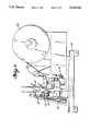
- FIG. 1is a front elevation of the extended input assembly of the instant invention, with the feeder stations illustrated fragmentarily.
- FIG. 2is a left side elevation of the device of FIG. 1, but with a feeder reel fully illustrated.
- FIG. 3is a fragmentary front elevation of the extended input and the relation of the supply shuttle to the transfer assembly with utility and test pockets.
- FIG. 4is a partial right side elevation of the device of FIG. 3.
- FIG. 5is a front elevation of the utility transfer pocket.
- FIG. 6is a left side elevation, partially in cross-section, of FIG. 5.
- FIG. 7is a top plan view of FIG. 6.
- FIG. 8is a schematic view of a prior art linear vibratory feeder and a stop for the bulk components fed thereby.
- FIG. 9is a fragmentary view of the prior art taped supply used in feeder reels at supply stations of the extended input assembly.
- FIG. 10is a view similar to FIG. 8, and illustrating a modified stop for grossly reorienting components fed by the vibrator linear feeder.
- FIG. 11ais an enlarged, top plan view of the stop of FIG. 10.
- FIG. 11bis a right side elvation of FIG. 11a.
- FIG. 12is a schematic top plan view of a pick and place machine and the positional relation thereof to the supply and transfer shuttles of the instant invention.
- FIG. 13is a top plan view of the transfer assembly, without the utility and test pockets mounted thereon.
- FIG. 14is a right side elevation of FIG. 13.
- a pick and place surface mounting machine 1may have a circuit board feedthrough axis 8 along which circuit boards are transported during population thereof with components.
- Each such surface mounting machine 1usually has a limited number of input stations mounted on integral mounting plates 7 which are adjustable to the illustrated phantom line positions in accordance with different sizes of circuit boards to be passed along axis 8.
- FIG. 12provides a top plan schematic view illustrating the positional relationship between such a surface mounting machine 1 and four extended input assemblies 2 and a corresponding number of transfer assemblies 3 of the instant invention.
- the onsertion machine 1will have two pick and place heads.
- an extended input assemblycomprises a mounting frame 10 supporting a bracket 11 to which a pair of Thompson rods 12 are mounted.
- Rods 12slidingly support a supply shuttle 20 upon which a pair of vacuum nozzle heads 22,24 are mounted.
- a pair of pulleys 15support a timing belt 16 which is attached to shuttle 20 in order to drive it along rods 12 according to drive assembly 14.
- Drive assembly 14may comprise a motor and encoder to ensure selective positioning of shuttle 20 along rods 12.
- a plurality of supply stations 26are positioned along the length of frame 10 and may take the form of a tape feeder 28 (as shown in FIG. 2) as well as vibratory feeders.
- shuttle 20is selectively positioned so that at least one of the vacuum nozzles 22,24 may retrieve a component 5 from a selected supply station 26 and then deliver the component 5 to a shuttle unload station.
- shuttle 20is located at the unload station of the extended input assembly 2 so that a component delivered thereto from a supply station 26 may be deposited in one of two pockets 48,50 of a transfer assembly 3.
- Transfer assembly 3has Thompson rods 42 along which a transfer shuttle 46 is reciprocatable by a drive assembly (not shown) similar to drive assembly 14 of extended input assembly 2.
- Mounted on transfer shuttle 46are a test pocket 48 and a utility pocket 50 into which components 5 are selectively deposited according to whether or not electrical functioning thereof is to be tested. If electrical functioning of a component 5 is to be tested, then head assembly 24 deposits the component 5 into test pocket 48 for squaring of the component 5 and testing of electrical functioning thereof.
- test pocket 48A detailed disclosure of test pocket 48 may be found in the above cross-referenced U.S. application Ser. No. 693,987, now U.S. Pat. No. 4,721,907, except that the component receiving platform of the tester of the instant invention is not spring biased upwardly since the placement nozzle 24 will not remain on the component during subsequent testing thereof.
- Utility pocket 50is provided in order to square and transport components which do not require testing just prior to placement thereof.
- Utility pocket 50comprises a platform 66 upon which components are placed, and squaring arms 52 which are pivotal between an open and closed position about pivot points 56.
- a cam 60is reciprocatable along camming surfaces 58 of the squaring arms 52 in order to open arms 52 against the biasing of springs 54.
- Cam 60is attached to actuator rod 62 which, in turn, is attached to a piston rod via clevis 64, so that firing of cylinder 68 raises rod 62 and opens arms 52 through the camming action.
- FIG. 9illustrates a tape 30 of the reeled supply 28 wherein individual components 5 are encased in and spaced along tape 30.
- FIG. 8illustrates the manner in which components 5 of the same general nature as those supplied in tapes 30 are fed to a stop 34 of a linear vibratory feeder 32 in an orientation which is 90° relative to the presentation of such components 5 by tape 30.
- FIGS. 10 and 11illustrate an improved stop 34 by which the components fed by vibratory feeder 32 are reoriented to correspond to the orientation of components supplied by tapes 30. In this way, all of the components to be tested are positioned properly for subsequent testing.
- the improved stop 34includes a reorientation groove 36 by which the vibratorily fed components 5 are reoriented.
- a cover 38is provided over the reorientation portion of groove 36 and is further provided with a pointed portion 40 extending past the end of stop 34. Any components which reach stop 34 in an orientation in which they are "on edge", and thus unacceptable for subsequent handling, are diverted off of the feed rail of laboratory feeder 32 by pointed tip portion 40.
- Typical components that may be handled by the instant inventioninclude SOT, SOIC, chip capacitors, chip resistors, diodes, and chip carriers with sizes ranging from 0.080 inches by 0.040 inches to 1.25 inches square.
- transfer assembly 3may be testing a particular component while transporting it between the shuttle unload station and the pick up position of the surface mounting machine and while shuttle 20 of the extended input 2 is retrieving another component from a selected supply station 26 and delivering the component to the shuttle unload station.
- Such an arrangementprovides a time sharing capability that allows faster supply of components to the onsertion machine.
Landscapes
- Physics & Mathematics (AREA)
- General Physics & Mathematics (AREA)
- Supply And Installment Of Electrical Components (AREA)
Abstract
Description
Claims (11)
Priority Applications (1)
| Application Number | Priority Date | Filing Date | Title |
|---|---|---|---|
| US07/616,765US5023544A (en) | 1987-04-03 | 1990-11-20 | Extended input and testing of electrical components for onsertion machines |
Applications Claiming Priority (2)
| Application Number | Priority Date | Filing Date | Title |
|---|---|---|---|
| US3384387A | 1987-04-03 | 1987-04-03 | |
| US07/616,765US5023544A (en) | 1987-04-03 | 1990-11-20 | Extended input and testing of electrical components for onsertion machines |
Related Parent Applications (1)
| Application Number | Title | Priority Date | Filing Date |
|---|---|---|---|
| US3384387AContinuation | 1987-04-03 | 1987-04-03 |
Publications (1)
| Publication Number | Publication Date |
|---|---|
| US5023544Atrue US5023544A (en) | 1991-06-11 |
Family
ID=26710205
Family Applications (1)
| Application Number | Title | Priority Date | Filing Date |
|---|---|---|---|
| US07/616,765Expired - LifetimeUS5023544A (en) | 1987-04-03 | 1990-11-20 | Extended input and testing of electrical components for onsertion machines |
Country Status (1)
| Country | Link |
|---|---|
| US (1) | US5023544A (en) |
Cited By (12)
| Publication number | Priority date | Publication date | Assignee | Title |
|---|---|---|---|---|
| US5151650A (en)* | 1991-09-03 | 1992-09-29 | Motorola, Inc. | Packaged semiconductor device handler |
| US5168218A (en)* | 1990-06-01 | 1992-12-01 | Rich Donald S | Tray-to-tray circuit package handler |
| US5172049A (en)* | 1990-10-15 | 1992-12-15 | Advantest Corporation | IC test equipment |
| US5177435A (en)* | 1990-10-12 | 1993-01-05 | Advantest Corporation | IC test equipment |
| US5910878A (en)* | 1997-06-26 | 1999-06-08 | International Business Machines Corporation | Method and apparatus for protecting electrical devices from static electricity |
| US6077022A (en)* | 1997-02-18 | 2000-06-20 | Zevatech Trading Ag | Placement machine and a method to control a placement machine |
| US6119926A (en)* | 1998-02-19 | 2000-09-19 | Esec Sa | Method for producing wire connections on semiconductor chips |
| US6129040A (en)* | 1997-09-05 | 2000-10-10 | Esec Sa | Semi-conductor mounting apparatus for applying adhesive to a substrate |
| US6131799A (en)* | 1998-01-15 | 2000-10-17 | Esec Sa | Method of making wire connections of predetermined shape |
| US6157870A (en)* | 1997-02-18 | 2000-12-05 | Zevatech Trading Ag | Apparatus supplying components to a placement machine with splice sensor |
| US6179938B1 (en) | 1997-10-30 | 2001-01-30 | Esec Sa | Method and apparatus for aligning the bonding head of a bonder, in particular a die bonder |
| US6737873B2 (en)* | 2000-10-26 | 2004-05-18 | Kel Corporation | Electronic part inspection device |
Citations (10)
| Publication number | Priority date | Publication date | Assignee | Title |
|---|---|---|---|---|
| US3304499A (en)* | 1962-11-27 | 1967-02-14 | Gen Instrument Corp | Escapement and contact mechanism having separately acting series controllers for testing electronic components |
| US4212075A (en)* | 1978-10-10 | 1980-07-08 | Usm Corporation | Electrical component testing system for component insertion machine |
| JPS55125800A (en)* | 1979-03-22 | 1980-09-27 | Citizen Watch Co Ltd | Sound body for watch |
| JPS56124997A (en)* | 1980-03-07 | 1981-09-30 | Kogyo Gijutsuin | Automatic vehicle traffic flow speed distribution detecting method |
| JPS56126389A (en)* | 1980-03-10 | 1981-10-03 | Fuji Photo Film Co Ltd | Predictive encoding system |
| US4320339A (en)* | 1977-11-07 | 1982-03-16 | Usm Corporation | Component testing station |
| JPS5748672A (en)* | 1980-05-27 | 1982-03-20 | Decca Ltd | Apparatus for obtaining phase of fundamental frequency from phase value of higher harmonics |
| JPS57145394A (en)* | 1981-03-03 | 1982-09-08 | Matsushita Electric Industrial Co Ltd | Device for mounting electronic part |
| JPS57148672A (en)* | 1981-03-09 | 1982-09-14 | Brother Ind Ltd | Paper feeder for printer |
| US4593820A (en)* | 1984-03-28 | 1986-06-10 | International Business Machines Corporation | Robotic, in-transit, device tester/sorter |
- 1990
- 1990-11-20USUS07/616,765patent/US5023544A/ennot_activeExpired - Lifetime
Patent Citations (10)
| Publication number | Priority date | Publication date | Assignee | Title |
|---|---|---|---|---|
| US3304499A (en)* | 1962-11-27 | 1967-02-14 | Gen Instrument Corp | Escapement and contact mechanism having separately acting series controllers for testing electronic components |
| US4320339A (en)* | 1977-11-07 | 1982-03-16 | Usm Corporation | Component testing station |
| US4212075A (en)* | 1978-10-10 | 1980-07-08 | Usm Corporation | Electrical component testing system for component insertion machine |
| JPS55125800A (en)* | 1979-03-22 | 1980-09-27 | Citizen Watch Co Ltd | Sound body for watch |
| JPS56124997A (en)* | 1980-03-07 | 1981-09-30 | Kogyo Gijutsuin | Automatic vehicle traffic flow speed distribution detecting method |
| JPS56126389A (en)* | 1980-03-10 | 1981-10-03 | Fuji Photo Film Co Ltd | Predictive encoding system |
| JPS5748672A (en)* | 1980-05-27 | 1982-03-20 | Decca Ltd | Apparatus for obtaining phase of fundamental frequency from phase value of higher harmonics |
| JPS57145394A (en)* | 1981-03-03 | 1982-09-08 | Matsushita Electric Industrial Co Ltd | Device for mounting electronic part |
| JPS57148672A (en)* | 1981-03-09 | 1982-09-14 | Brother Ind Ltd | Paper feeder for printer |
| US4593820A (en)* | 1984-03-28 | 1986-06-10 | International Business Machines Corporation | Robotic, in-transit, device tester/sorter |
Non-Patent Citations (2)
| Title |
|---|
| Hoebener, K. G.; "Multiple Size Chip Pickup, Orientation and Placement Station"; IBM Tech. Dis. Bull. vol. 22; No. 7; Dec. 1979; pp. 2757-2761. |
| Hoebener, K. G.; Multiple Size Chip Pickup, Orientation and Placement Station ; IBM Tech. Dis. Bull. vol. 22; No. 7; Dec. 1979; pp. 2757 2761.* |
Cited By (12)
| Publication number | Priority date | Publication date | Assignee | Title |
|---|---|---|---|---|
| US5168218A (en)* | 1990-06-01 | 1992-12-01 | Rich Donald S | Tray-to-tray circuit package handler |
| US5177435A (en)* | 1990-10-12 | 1993-01-05 | Advantest Corporation | IC test equipment |
| US5172049A (en)* | 1990-10-15 | 1992-12-15 | Advantest Corporation | IC test equipment |
| US5151650A (en)* | 1991-09-03 | 1992-09-29 | Motorola, Inc. | Packaged semiconductor device handler |
| US6077022A (en)* | 1997-02-18 | 2000-06-20 | Zevatech Trading Ag | Placement machine and a method to control a placement machine |
| US6157870A (en)* | 1997-02-18 | 2000-12-05 | Zevatech Trading Ag | Apparatus supplying components to a placement machine with splice sensor |
| US5910878A (en)* | 1997-06-26 | 1999-06-08 | International Business Machines Corporation | Method and apparatus for protecting electrical devices from static electricity |
| US6129040A (en)* | 1997-09-05 | 2000-10-10 | Esec Sa | Semi-conductor mounting apparatus for applying adhesive to a substrate |
| US6179938B1 (en) | 1997-10-30 | 2001-01-30 | Esec Sa | Method and apparatus for aligning the bonding head of a bonder, in particular a die bonder |
| US6131799A (en)* | 1998-01-15 | 2000-10-17 | Esec Sa | Method of making wire connections of predetermined shape |
| US6119926A (en)* | 1998-02-19 | 2000-09-19 | Esec Sa | Method for producing wire connections on semiconductor chips |
| US6737873B2 (en)* | 2000-10-26 | 2004-05-18 | Kel Corporation | Electronic part inspection device |
Similar Documents
| Publication | Publication Date | Title |
|---|---|---|
| US6176011B1 (en) | Electronic parts supplying device and electronic parts mounting method | |
| USRE32538E (en) | Head for handling electrical components | |
| US5023544A (en) | Extended input and testing of electrical components for onsertion machines | |
| US4940935A (en) | Automatic SMD tester | |
| US5040291A (en) | Multi-spindle pick and place method and apparatus | |
| US4501064A (en) | Micro component assembly machine | |
| KR100496949B1 (en) | Method and apparatus for mounting electronic components | |
| EP0810817B1 (en) | Mounting systems and methods | |
| US4694570A (en) | Surface mounted component transport mechanism | |
| DE102017116042B4 (en) | Method and placement machine for equipping component carriers with electronic components | |
| JPS58124295A (en) | Automatic loading and unloading device for printed circuit board | |
| CA1086251A (en) | Component sequence verifier | |
| US6729017B1 (en) | Component mounter and mounting method | |
| US4551913A (en) | Component delivery system | |
| EP0259489B1 (en) | Working apparatus | |
| US6550133B1 (en) | Surface mounting apparatus installed with tray feeder | |
| US4769904A (en) | Method and apparatus for handling leaded and leadless surface mountable components | |
| KR100196365B1 (en) | Mount apparatus for solder ball of ball grid array | |
| CN219179243U (en) | PCB detection equipment | |
| CN219179244U (en) | PCB detection equipment | |
| US6532395B1 (en) | Manufacturing system with feeder/programming/buffer system | |
| EP0213746A2 (en) | Method and apparatus for handling leaded and leadless surface mountable components | |
| US5992611A (en) | Concurrent component mounter and method of concurrently mounting components | |
| JPH11289156A (en) | Solder ball mounting method and rotary solder ball feeding device | |
| JP3334224B2 (en) | Component mounting equipment |
Legal Events
| Date | Code | Title | Description |
|---|---|---|---|
| STCF | Information on status: patent grant | Free format text:PATENTED CASE | |
| AS | Assignment | Owner name:DELAWARE CAPITAL FORMATION, INC., A DE CORP., DELA Free format text:ASSIGNMENT OF ASSIGNORS INTEREST.;ASSIGNOR:UNIVERSAL INSTRUMENTS CORPORATION, A DE CORP.;REEL/FRAME:006021/0154 Effective date:19920210 | |
| FEPP | Fee payment procedure | Free format text:PAYOR NUMBER ASSIGNED (ORIGINAL EVENT CODE: ASPN); ENTITY STATUS OF PATENT OWNER: LARGE ENTITY | |
| FPAY | Fee payment | Year of fee payment:4 | |
| FPAY | Fee payment | Year of fee payment:8 | |
| FPAY | Fee payment | Year of fee payment:12 | |
| AS | Assignment | Owner name:UI HOLDING CO., NEW YORK Free format text:ASSIGNMENT OF ASSIGNORS INTEREST;ASSIGNOR:DELAWARE CAPITAL FORMATION, INC.;REEL/FRAME:018711/0207 Effective date:20061106 | |
| AS | Assignment | Owner name:MORGAN STANLEY SENIOR FUNDING, INC., NEW YORK Free format text:PLEDGE AND SECURITY AGREEMENT (FIRST LIEN);ASSIGNOR:UI HOLDING CO.;REEL/FRAME:020270/0755 Effective date:20061106 | |
| AS | Assignment | Owner name:PATRIARCH PARTNERS AGENCY SERVICES, LLC, AS THE AD Free format text:CHANGE OF ADMINISTRATIVE AGENT;ASSIGNOR:MORGAN STANLEY SENIOR FUNDING INC., AS THE ADMINISTRATIVE AGENT;REEL/FRAME:024640/0963 Effective date:20081118 |