US5023502A - Switched reluctance motor rotor - Google Patents
Switched reluctance motor rotorDownload PDFInfo
- Publication number
- US5023502A US5023502AUS07/429,823US42982389AUS5023502AUS 5023502 AUS5023502 AUS 5023502AUS 42982389 AUS42982389 AUS 42982389AUS 5023502 AUS5023502 AUS 5023502A
- Authority
- US
- United States
- Prior art keywords
- hub
- rotor
- gaps
- tang
- axial
- Prior art date
- Legal status (The legal status is an assumption and is not a legal conclusion. Google has not performed a legal analysis and makes no representation as to the accuracy of the status listed.)
- Expired - Fee Related
Links
Images

Classifications
- H—ELECTRICITY
- H02—GENERATION; CONVERSION OR DISTRIBUTION OF ELECTRIC POWER
- H02K—DYNAMO-ELECTRIC MACHINES
- H02K1/00—Details of the magnetic circuit
- H02K1/06—Details of the magnetic circuit characterised by the shape, form or construction
- H02K1/22—Rotating parts of the magnetic circuit
- H02K1/24—Rotor cores with salient poles ; Variable reluctance rotors
- H02K1/246—Variable reluctance rotors
Definitions
- the inventionrelates to switched reluctance electric motor rotors, and more particularly to retention structure enhancing the hold-together strength of the rotor laminations.
- the rotorcomprises a plurality of rotor laminations stacked axially to form a laminated stack having axial ends.
- the rotorincludes a central annular hub having a plurality of rotor poles extending radially outwardly from the hub.
- the rotor polesare circumferentially spaced and have gaps therebetween.
- the laminationsare electrically insulated from each other, to minimize interlaminar current.
- the laminationsare typically glued together with epoxy or similar adhesive material which is cured while the laminations are held together under pressure.
- the present inventionprovides simple and effective structure enhancing the hold-together strength of the laminated rotor stack.
- FIG. 1is a sectional view of a switched reluctance motor known in the prior art.
- FIG. 2is a perspective view of the motor rotor of FIG. 1.
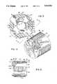
- FIG. 3is a sectional view of a switched reluctance motor rotor in accordance with the invention.
- FIG. 4is a perspective view of the rotor of FIG. 3.
- FIG. 5is a side elevation view, partially cut away, taken along line 5--5 of FIG. 3.
- FIG. 1shows a switched reluctance motor 10 including stator 12 and rotor 14.
- the stator and rotoreach comprise a plurality of laminations, and FIG. 1 shows a single lamination of each.
- the statorhas a plurality of circumferentially spaced stator poles such as 16 with slots such as 18 therebetween.
- the slotsreceive windings 20 around the stator poles.
- the windingsare retained in the slots by wedges such as 22.
- the rotorcomprises a central annular hub 24 having a plurality of rotor poles 25, 26, 27, 28 extending radially outwardly from the hub.
- the rotor polesare circumferentially spaced and have gaps 29, 30, 31, 32 therebetween.
- FIG. 2shows a plurality of rotor laminations 42, 43, etc. stacked axially to form the laminated stack having axial ends 44 and 46. Insulating material 37-40 enhances the hold-together strength of the stack.
- FIG. 3shows a switched reluctance motor rotor 50 in accordance with the invention.
- the rotorcomprises a central annular hub 52 having a plurality of rotor poles 53, 54, 55, 56 extending radially outwardly therefrom.
- the rotor polesare circumferentially spaced and have gaps 57, 58, 59, 60 therebetween.
- Retention structureis provided on hub 52 in the gaps in the form of tangs 61, 62, 63, 64 extending radially outwardly from hub 52 into gaps 57, 58, 59, 60, respectively.
- Electrically insulating material 65, 66, 67, 68such as bakelite, nylon, or valox, is provided in gaps 57, 58, 59, 60, respectively, and retained therein by tangs 61, 62, 63, 64, respectively.
- Each of tangs 61-64has a radial length substantially less than the radial length of rotor poles 53-56 such that the outer tip such as 70 of the tang is spaced substantially radially inwardly of the arc of travel of the outer tip such as 72 of the rotor pole. This is desirable because it minimizes magnetic flux path lines through the tang, in contrast to fingers 34, and 36 of FIGS. 1 and 2.
- Tang 61has distally opposite sides 74 and 76 with inner root ends 78 and 80 at hub 52 and outer ends 82 and 84 spaced radially outwardly of hub 52.
- the circumferential spacing between inner root ends 78 and 80is less than the circumferential spacing between outer ends 82 and 84.
- Distally opposite sides 74 and 76diverge away from each other as they extend away from hub 52. The remaining tangs are comparable.
- FIG. 4shows a plurality of rotor laminations 86, 87, etc. stacked axially to form a laminated stack having axial ends 88 and 90.
- Electric insulation material 65-68is part of a one-piece unitary harness 92 molded in-situ axially around the laminated stack and structurally enhancing the hold-together strength thereof.
- Harness 92has a plurality of axial runners provided by the noted insulation material 65, 66, 67, 68 extending axially along gaps 57, 58, 59, 60, respectively, and integral with a pair of annular end rings 94 and 96 on axial ends 88 and 90.
- Insulating material 65-68extend axially beyond the end rotor laminations 86 and 98 of the laminated stack and merge into annular end rings 94 and 96.
- Axial runners 65-68have a given radial extension in respective gaps 57-60, and annular end rings 94 and 96 have a given radial extension at least partially overlapping the radial extension of axial runners provided by insulating material 65-68.
- the outer radius 100 of axial runners provided by insulating material 65-68is the same as the outer radius 102 of annular end rings 94 and 96.
- the inner radius 104 of axial runners provided by insulating material 65-68is greater than the inner radius 106 of annular end rings 94 and 96.
- the inner radius 106 of annular end rings 94 and 96is greater than the inner radius 108 of rotor 50.
- the electrically molded insulating material 65-68 integrally formed both in gaps 57-60 and on axial ends 88 and 90provides in combination axial runners provided by insulating material 65-68 extending axially along gaps 57-60 and integral with annular end rings 94 and 96 of molded material on axial ends 88 and 90, which combination further structurally enhances the hold-together strength of the laminated stack.
- FIGS. 3 and 4show only one tang between poles, the invention is not limited thereto, but can use one or more tangs.
Landscapes
- Engineering & Computer Science (AREA)
- Power Engineering (AREA)
- Synchronous Machinery (AREA)
- Iron Core Of Rotating Electric Machines (AREA)
Abstract
Description
The invention relates to switched reluctance electric motor rotors, and more particularly to retention structure enhancing the hold-together strength of the rotor laminations.
In a switched reluctance motor, the rotor comprises a plurality of rotor laminations stacked axially to form a laminated stack having axial ends. The rotor includes a central annular hub having a plurality of rotor poles extending radially outwardly from the hub. The rotor poles are circumferentially spaced and have gaps therebetween. The laminations are electrically insulated from each other, to minimize interlaminar current. The laminations are typically glued together with epoxy or similar adhesive material which is cured while the laminations are held together under pressure.
The present invention provides simple and effective structure enhancing the hold-together strength of the laminated rotor stack.
FIG. 1 is a sectional view of a switched reluctance motor known in the prior art.
FIG. 2 is a perspective view of the motor rotor of FIG. 1.
FIG. 3 is a sectional view of a switched reluctance motor rotor in accordance with the invention.
FIG. 4 is a perspective view of the rotor of FIG. 3.
FIG. 5 is a side elevation view, partially cut away, taken alongline 5--5 of FIG. 3.
FIG. 1 shows a switched reluctance motor 10 includingstator 12 androtor 14. The stator and rotor each comprise a plurality of laminations, and FIG. 1 shows a single lamination of each. The stator has a plurality of circumferentially spaced stator poles such as 16 with slots such as 18 therebetween. The slots receivewindings 20 around the stator poles. The windings are retained in the slots by wedges such as 22. The rotor comprises a central annular hub 24 having a plurality ofrotor poles gaps material rotor laminations axial ends
FIG. 3 shows a switchedreluctance motor rotor 50 in accordance with the invention. The rotor comprises a centralannular hub 52 having a plurality ofrotor poles gaps hub 52 in the gaps in the form oftangs hub 52 intogaps material gaps tangs
Each of tangs 61-64 has a radial length substantially less than the radial length of rotor poles 53-56 such that the outer tip such as 70 of the tang is spaced substantially radially inwardly of the arc of travel of the outer tip such as 72 of the rotor pole. This is desirable because it minimizes magnetic flux path lines through the tang, in contrast tofingers
Tang 61 has distallyopposite sides inner root ends hub 52 andouter ends hub 52. The circumferential spacing betweeninner root ends outer ends opposite sides hub 52. The remaining tangs are comparable.
FIG. 4 shows a plurality ofrotor laminations axial ends unitary harness 92 molded in-situ axially around the laminated stack and structurally enhancing the hold-together strength thereof. Harness 92 has a plurality of axial runners provided by the notedinsulation material gaps annular end rings axial ends end rotor laminations annular end rings annular end rings outer radius 102 ofannular end rings inner radius 104 of axial runners provided by insulating material 65-68 is greater than theinner radius 106 ofannular end rings inner radius 106 ofannular end rings inner radius 108 ofrotor 50.
The electrically molded insulating material 65-68 integrally formed both in gaps 57-60 and onaxial ends annular end rings axial ends
It is recognized that various equivalents, alternatives and modifications are possible within the scope of the appended claims. For example, although the drawings show four poles, the invention is not limited to that number but rather can be used with two, four, six or eight, or any number of rotor poles. Furthermore, although FIGS. 3 and 4 show only one tang between poles, the invention is not limited thereto, but can use one or more tangs.
Claims (9)
1. A switched reluctance motor rotor comprising a central annular hub having a plurality of rotor poles extending radially outwardly from said hub, said rotor poles being circumferentially spaced and having gaps therebetween, retention structure on said hub in said gaps, and electrically insulating material in said gaps and retained therein by said retention structure, wherein said rotor comprises a plurality of rotor laminations stacked axially to form a laminated stack, and wherein said retention structure comprises a tang integrally formed with each of said rotor laminations and extending from said hub into a respective one of said gaps.
2. The invention according to claim 1 wherein said tang has an outer tip and extends radially outwardly from said hub and has a radial length substantially less than the radial length of a respective one of said rotor poles such that the outer tip of said tang is spaced substantially radially inwardly of the arc of travel of the outer tip of said rotor pole, to minimize flux path lines through said tang.
3. A switched reluctance motor rotor comprising a central annular hub having a plurality of rotor poles extending radially outwardly from said hub, said rotor poles being circumferentially spaced and having gaps therebetween, retention structure on said hub in said gaps, and electrically insulating material in said gaps and retained therein by said retention structure, wherein said retention structure comprises a tang extending from said hub into a respective one of said gaps, and wherein said tang has distally opposite sides with inner root ends at said hub and outer ends spaced radially outwardly of said hub, and wherein the circumferential spacing between said inner root ends is less than the circumferential spacing between said outer ends.
4. The invention according to claim 3 wherein said distally opposite sides of said tang diverge away from each other as they extend away from said hub.
5. A switched reluctance motor rotor comprising a plurality of rotor laminations stacked axially to form a laminated stack having axial ends and comprising a central annular hub having a plurality of rotor poles extending radially outwardly from said hub, said rotor poles being circumferentially spaced and having gaps therebetween, a one-piece unitary harness molded in-situ axially around said laminated stack, wherein said harness is molded of electrically insulating material and has a plurality of axial runners extending axially along said gaps and integral with a pair of annular end rings on said axial ends, wherein said axial runners extend axially beyond the rotor laminations of said laminated stack and merge into said annular end rings, wherein said axial runners have a given radial extension, and wherein said annular end rings have a given radial extension at least partially overlapping said radial extension of said axial runners, wherein said axial runners have an outer radius, and said annular end rings have an outer radius, and wherein the outer radius of said axial runners is the same as the outer radius of said annular end rings and a retention tang integral with each of the rotor laminations and extending from said hub into a respective one of said gaps.
6. A switched reluctance motor rotor comprising a plurality of rotor laminations stacked axially to form a laminated stack having axial ends and comprising a central annular hub having a plurality of rotor poles extending radially outwardly from said hub, said rotor poles being circumferentially spaced and having gaps therebetween, a one-piece unitary harness molded in-situ axially around said laminated stack, wherein said harness is molded of electrically insulating material and has a plurality of axial runners extending axially along said gaps and integral with a pair of annular end rings on said axial ends, wherein said axial runners extend axially beyond the rotor laminations of said laminated stack and merge into said annular end rings, wherein said axial runners have a given radial extension, and wherein said annular end rings have a given radial extension at least partially overlapping said radial extension of said axial runners, wherein said annular end rings have an inner radius, and said rotor has an inner radius, and wherein the inner radius of said annular end rings is greater than the inner radius of said rotor and a retention tang and a retention tang integral with each of the rotor laminations and extending from said hub into a respective one of said gaps.
7. A switched reluctance motor rotor comprising a plurality of rotor laminations stacked axially to form a laminated stack having axial ends and comprising a central annular hub having a plurality of rotor poles extending radially outwardly from said hub, said rotor poles being circumferentially spaced and having gaps therebetween, electrically insulating molded material integrally formed both in said gaps and on said axial ends to provide in combination axial runners of said molded material extending axially along said gaps and integral with annular end rings of said molded material on said axial ends, and comprising retention structure on said hub in said gaps, and wherein said molded material in said gaps is further retained therein by said retention structure, wherein said retention structure comprises a tang integrally formed with each of said rotor laminations and extending outwardly from said hub into a respective one of said gaps.
8. The invention according to claim 7 wherein said tang has an outer tip and extends radially outwardly from said hub and has a radial length substantially less than the radial length of said rotor pole such that the outer tip of said tang is spaced substantially radially inwardly of the arc of travel of the outer tip of said rotor pole, to minimize flux path lines through said tang.
9. The invention according to claim 7 wherein said tang has distally opposite sides with inner root ends at said hub and outer ends spaced radially outwardly of said hub, and wherein the circumferential spacing between said inner root ends is less then the circumferential spacing between said outer ends.
Priority Applications (5)
| Application Number | Priority Date | Filing Date | Title |
|---|---|---|---|
| US07/429,823US5023502A (en) | 1989-10-31 | 1989-10-31 | Switched reluctance motor rotor |
| CA002027393ACA2027393C (en) | 1989-10-31 | 1990-10-11 | Switched reluctance motor rotor |
| IE381490AIE63957B1 (en) | 1989-10-31 | 1990-10-23 | Switched reluctance motor rotor |
| EP90311716AEP0426376B1 (en) | 1989-10-31 | 1990-10-25 | Switched reluctance motor rotor |
| DE90311716TDE69004935T2 (en) | 1989-10-31 | 1990-10-25 | Rotor for a clocked reluctance motor. |
Applications Claiming Priority (1)
| Application Number | Priority Date | Filing Date | Title |
|---|---|---|---|
| US07/429,823US5023502A (en) | 1989-10-31 | 1989-10-31 | Switched reluctance motor rotor |
Publications (1)
| Publication Number | Publication Date |
|---|---|
| US5023502Atrue US5023502A (en) | 1991-06-11 |
Family
ID=23704871
Family Applications (1)
| Application Number | Title | Priority Date | Filing Date |
|---|---|---|---|
| US07/429,823Expired - Fee RelatedUS5023502A (en) | 1989-10-31 | 1989-10-31 | Switched reluctance motor rotor |
Country Status (5)
| Country | Link |
|---|---|
| US (1) | US5023502A (en) |
| EP (1) | EP0426376B1 (en) |
| CA (1) | CA2027393C (en) |
| DE (1) | DE69004935T2 (en) |
| IE (1) | IE63957B1 (en) |
Cited By (33)
| Publication number | Priority date | Publication date | Assignee | Title |
|---|---|---|---|---|
| US5117144A (en)* | 1988-08-25 | 1992-05-26 | Toeroek Vilmos | Electric motor |
| US5256923A (en)* | 1992-05-11 | 1993-10-26 | A. O. Smith Corporation | Switched reluctance motor with sensorless position detection |
| US5345131A (en)* | 1990-12-28 | 1994-09-06 | Toeroek Vilmos | Electric motor with combined permanent and electromagnets |
| US5604388A (en)* | 1994-02-16 | 1997-02-18 | Emerson Electric Co. | Switched reluctance rotor molded lug |
| US5693250A (en)* | 1993-04-20 | 1997-12-02 | General Motors Corporation | Grain oriented composite soft magnetic structure |
| US5703421A (en)* | 1996-05-24 | 1997-12-30 | The United States Of America As Represented By The Secretary Of The Air Force | Reluctance generator/motor cooling |
| US5726516A (en)* | 1995-04-07 | 1998-03-10 | Switched Reluctance Drives, Ltd. | Rotor for high speed switched reluctance machine |
| US5780945A (en)* | 1997-03-24 | 1998-07-14 | Emerson Electric Co. | Switched reluctance machine balancing system: material removal approach and material addition approach |
| US5852334A (en)* | 1995-10-19 | 1998-12-22 | Tridelta Industries, Inc. | Staggered pole switched reluctance motor |
| US5892306A (en)* | 1997-03-24 | 1999-04-06 | Emerson Electric Co. | Method and apparatus for balancing a load with a salient pole rotor machine |
| US5949170A (en)* | 1995-04-10 | 1999-09-07 | Switched Reluctance Drives, Ltd | Method and apparatus for reducing voltage stresses in electric machine |
| US5969454A (en)* | 1995-10-19 | 1999-10-19 | Tridelta Industries, Inc. | Switched reluctance motor |
| US6028385A (en)* | 1995-10-19 | 2000-02-22 | Tridelta Industries, Inc. | Switched reluctance motor |
| US6051903A (en)* | 1995-10-19 | 2000-04-18 | Tridelta Industries, Inc. | Switched reluctance motor |
| US6060809A (en)* | 1995-10-19 | 2000-05-09 | Tridelta Industries, Inc. | Staggered pole switched reluctance motor |
| WO2000064028A1 (en)* | 1999-04-20 | 2000-10-26 | Thermo Black Clawson Inc. | High efficiency submersible electric motor and components |
| US6144131A (en)* | 1995-06-07 | 2000-11-07 | General Electric Company | Dynamoelectric machine rotor having interleaved laminations and method for forming |
| US6707206B2 (en)* | 2002-01-23 | 2004-03-16 | Energy Saving Tech. Corp. | Magnetic material fixing structure of motor rotor |
| KR100465712B1 (en)* | 2002-11-04 | 2005-01-13 | 엘지전자 주식회사 | Switched reluctance motor |
| US6911756B1 (en)* | 2004-03-23 | 2005-06-28 | Chio-Sung Chang | Rotor core with magnets on the outer periphery of the core having a sine or trapezoidal wave |
| US20060061227A1 (en)* | 2004-09-21 | 2006-03-23 | A.O. Smith Corporation | Spoke permanent magnet rotor |
| US20060097596A1 (en)* | 2004-11-08 | 2006-05-11 | Desai Piyush C | Switched reluctance machine |
| US20070132336A1 (en)* | 2005-12-08 | 2007-06-14 | Ionel Dan M | Rotor assembly for an electric machine including a vibration damping member and method of manufacturing same |
| US20070132335A1 (en)* | 2005-12-08 | 2007-06-14 | Ionel Dan M | Rotor assembly having a reduced back portion and a method of manufacturing same |
| US20070222326A1 (en)* | 2005-12-08 | 2007-09-27 | A.O. Smith Corporation | Rotor assembly having a reduced back portion and a method of manufacturing same |
| WO2012004609A2 (en) | 2010-07-09 | 2012-01-12 | Imra Europe S.A.S. | Electric motor |
| US20130038161A1 (en)* | 2011-08-11 | 2013-02-14 | Zhongshan Broad-Ocean Motor Manufacturing Co., Ltd. | Permanent magnet rotor |
| US9099905B2 (en) | 2012-10-15 | 2015-08-04 | Regal Beloit America, Inc. | Radially embedded permanent magnet rotor and methods thereof |
| US9246364B2 (en) | 2012-10-15 | 2016-01-26 | Regal Beloit America, Inc. | Radially embedded permanent magnet rotor and methods thereof |
| US9362792B2 (en) | 2012-10-15 | 2016-06-07 | Regal Beloit America, Inc. | Radially embedded permanent magnet rotor having magnet retention features and methods thereof |
| US9831727B2 (en) | 2012-10-15 | 2017-11-28 | Regal Beloit America, Inc. | Permanent magnet rotor and methods thereof |
| US9882440B2 (en) | 2012-10-15 | 2018-01-30 | Regal Beloit America, Inc. | Radially embedded permanent magnet rotor and methods thereof |
| US20210376676A1 (en)* | 2020-05-28 | 2021-12-02 | Hyundai Motor Company | Switched reluctance motor |
Families Citing this family (5)
| Publication number | Priority date | Publication date | Assignee | Title |
|---|---|---|---|---|
| EP0625819A1 (en)* | 1993-05-19 | 1994-11-23 | Siemens Aktiengesellschaft | Reluctance motor, in particular for driving a washing machine |
| GB9910392D0 (en) | 1999-05-05 | 1999-07-07 | Lucas Ind Plc | Rotor for an electrical machine,and an electrical machine including such a rotor |
| FR2903824A1 (en)* | 2006-07-13 | 2008-01-18 | Leroy Somer Moteurs | ROTOR OF ELECTRIC ROTATING MACHINE AND METHOD OF MANUFACTURING |
| KR20130002128A (en)* | 2011-06-28 | 2013-01-07 | 삼성전기주식회사 | Switched reluctance motor |
| DE102013201353A1 (en)* | 2012-02-10 | 2013-08-14 | Ksb Aktiengesellschaft | Rotor and reluctance motor |
Citations (17)
| Publication number | Priority date | Publication date | Assignee | Title |
|---|---|---|---|---|
| GB190508802A (en)* | 1905-04-26 | 1906-01-04 | John Scarisbrick Walker | Improvements in or in connection with Lubricating Valves. |
| FR1210349A (en)* | 1958-09-20 | 1960-03-08 | Electric machine rotor manufacturing process | |
| US3157806A (en)* | 1959-11-05 | 1964-11-17 | Bbc Brown Boveri & Cie | Synchronous machine with salient poles |
| US3588557A (en)* | 1969-02-19 | 1971-06-28 | Westinghouse Electric Corp | Low loss ventilation for salient pole machines |
| US3611556A (en)* | 1968-01-20 | 1971-10-12 | Nippon Denso Co | Method of manufacturing a rotor for small rotary electric machines |
| US3882336A (en)* | 1973-12-03 | 1975-05-06 | Briggs & Stratton Corp | Electric motor armature core |
| SU484604A1 (en)* | 1972-12-14 | 1975-09-15 | Центральное Проектно-Конструкторское И Технологическое Бюро Крупных Электрических Машин | Rotor of a synchronous electric pole machine |
| DE2605815A1 (en)* | 1976-02-11 | 1977-08-18 | Siemens Ag | Air cooling for salient pole electric machine rotors - uses ducts round pole windings inside rotor and serrated shields outside |
| JPS5330702A (en)* | 1976-09-02 | 1978-03-23 | Toshiba Corp | Salient-pole field coil supporter and its production method |
| JPS5537883A (en)* | 1978-09-09 | 1980-03-17 | Hitachi Ltd | Salient-pole rotor |
| US4260921A (en)* | 1978-12-26 | 1981-04-07 | The Garrett Corporation | Permanent magnet rotor assembly having rectangularly shaped tongues |
| US4504755A (en)* | 1983-11-03 | 1985-03-12 | Kollmorgen Technologies Corporation | Rotor reluctance notch for cogging control |
| US4525925A (en)* | 1983-09-22 | 1985-07-02 | General Electric Company | Method of making permanent magnet rotor |
| US4670696A (en)* | 1984-10-19 | 1987-06-02 | Kollmorgen Technologies Corporation | Variable speed variable reluctance electrical machines |
| US4674178A (en)* | 1985-10-16 | 1987-06-23 | Sundstrand Corporation | Method of fabricating a permanent magnet rotor |
| US4795933A (en)* | 1982-08-06 | 1989-01-03 | Hitachi, Ltd. | Salient-pole rotary electric machine |
| US4864174A (en)* | 1984-03-17 | 1989-09-05 | Isuzu Motors Limited | Generator device |
Family Cites Families (3)
| Publication number | Priority date | Publication date | Assignee | Title |
|---|---|---|---|---|
| DE304420C (en)* | ||||
| DE2317500A1 (en)* | 1973-04-04 | 1974-10-10 | Siemens Ag | ELECTRIC SYNCHRONOUS MACHINE HOMOPOLAR DESIGN |
| IT1208879B (en)* | 1987-04-30 | 1989-07-10 | Isoflux Servomotors Spa | ELECTRIC RELUCTANCE MACHINE |
- 1989
- 1989-10-31USUS07/429,823patent/US5023502A/ennot_activeExpired - Fee Related
- 1990
- 1990-10-11CACA002027393Apatent/CA2027393C/ennot_activeExpired - Fee Related
- 1990-10-23IEIE381490Apatent/IE63957B1/ennot_activeIP Right Cessation
- 1990-10-25DEDE90311716Tpatent/DE69004935T2/ennot_activeExpired - Fee Related
- 1990-10-25EPEP90311716Apatent/EP0426376B1/ennot_activeExpired - Lifetime
Patent Citations (17)
| Publication number | Priority date | Publication date | Assignee | Title |
|---|---|---|---|---|
| GB190508802A (en)* | 1905-04-26 | 1906-01-04 | John Scarisbrick Walker | Improvements in or in connection with Lubricating Valves. |
| FR1210349A (en)* | 1958-09-20 | 1960-03-08 | Electric machine rotor manufacturing process | |
| US3157806A (en)* | 1959-11-05 | 1964-11-17 | Bbc Brown Boveri & Cie | Synchronous machine with salient poles |
| US3611556A (en)* | 1968-01-20 | 1971-10-12 | Nippon Denso Co | Method of manufacturing a rotor for small rotary electric machines |
| US3588557A (en)* | 1969-02-19 | 1971-06-28 | Westinghouse Electric Corp | Low loss ventilation for salient pole machines |
| SU484604A1 (en)* | 1972-12-14 | 1975-09-15 | Центральное Проектно-Конструкторское И Технологическое Бюро Крупных Электрических Машин | Rotor of a synchronous electric pole machine |
| US3882336A (en)* | 1973-12-03 | 1975-05-06 | Briggs & Stratton Corp | Electric motor armature core |
| DE2605815A1 (en)* | 1976-02-11 | 1977-08-18 | Siemens Ag | Air cooling for salient pole electric machine rotors - uses ducts round pole windings inside rotor and serrated shields outside |
| JPS5330702A (en)* | 1976-09-02 | 1978-03-23 | Toshiba Corp | Salient-pole field coil supporter and its production method |
| JPS5537883A (en)* | 1978-09-09 | 1980-03-17 | Hitachi Ltd | Salient-pole rotor |
| US4260921A (en)* | 1978-12-26 | 1981-04-07 | The Garrett Corporation | Permanent magnet rotor assembly having rectangularly shaped tongues |
| US4795933A (en)* | 1982-08-06 | 1989-01-03 | Hitachi, Ltd. | Salient-pole rotary electric machine |
| US4525925A (en)* | 1983-09-22 | 1985-07-02 | General Electric Company | Method of making permanent magnet rotor |
| US4504755A (en)* | 1983-11-03 | 1985-03-12 | Kollmorgen Technologies Corporation | Rotor reluctance notch for cogging control |
| US4864174A (en)* | 1984-03-17 | 1989-09-05 | Isuzu Motors Limited | Generator device |
| US4670696A (en)* | 1984-10-19 | 1987-06-02 | Kollmorgen Technologies Corporation | Variable speed variable reluctance electrical machines |
| US4674178A (en)* | 1985-10-16 | 1987-06-23 | Sundstrand Corporation | Method of fabricating a permanent magnet rotor |
Non-Patent Citations (2)
| Title |
|---|
| "Brushless Permanent-Magnet and Reluctance Motor Drives", T. J. E. Miller, Clarendon Press, Oxford, 1989, pp. 150-189. |
| Brushless Permanent Magnet and Reluctance Motor Drives , T. J. E. Miller, Clarendon Press, Oxford, 1989, pp. 150 189.* |
Cited By (45)
| Publication number | Priority date | Publication date | Assignee | Title |
|---|---|---|---|---|
| US5117144A (en)* | 1988-08-25 | 1992-05-26 | Toeroek Vilmos | Electric motor |
| US5345131A (en)* | 1990-12-28 | 1994-09-06 | Toeroek Vilmos | Electric motor with combined permanent and electromagnets |
| USRE37027E1 (en)* | 1990-12-28 | 2001-01-23 | Toeroek Vilmos | Electric motor with combined permanent and electromagnets |
| US5256923A (en)* | 1992-05-11 | 1993-10-26 | A. O. Smith Corporation | Switched reluctance motor with sensorless position detection |
| US5693250A (en)* | 1993-04-20 | 1997-12-02 | General Motors Corporation | Grain oriented composite soft magnetic structure |
| US5604388A (en)* | 1994-02-16 | 1997-02-18 | Emerson Electric Co. | Switched reluctance rotor molded lug |
| US5726516A (en)* | 1995-04-07 | 1998-03-10 | Switched Reluctance Drives, Ltd. | Rotor for high speed switched reluctance machine |
| US5949170A (en)* | 1995-04-10 | 1999-09-07 | Switched Reluctance Drives, Ltd | Method and apparatus for reducing voltage stresses in electric machine |
| US6144131A (en)* | 1995-06-07 | 2000-11-07 | General Electric Company | Dynamoelectric machine rotor having interleaved laminations and method for forming |
| US6060809A (en)* | 1995-10-19 | 2000-05-09 | Tridelta Industries, Inc. | Staggered pole switched reluctance motor |
| US5969454A (en)* | 1995-10-19 | 1999-10-19 | Tridelta Industries, Inc. | Switched reluctance motor |
| US6028385A (en)* | 1995-10-19 | 2000-02-22 | Tridelta Industries, Inc. | Switched reluctance motor |
| US6046568A (en)* | 1995-10-19 | 2000-04-04 | Tridelta Industries, Inc. | Staggered pole switched reluctance motor |
| US6051903A (en)* | 1995-10-19 | 2000-04-18 | Tridelta Industries, Inc. | Switched reluctance motor |
| US5852334A (en)* | 1995-10-19 | 1998-12-22 | Tridelta Industries, Inc. | Staggered pole switched reluctance motor |
| US6114789A (en)* | 1995-10-19 | 2000-09-05 | Tridelta Industries, Inc. | Switched reluctance motor |
| US5703421A (en)* | 1996-05-24 | 1997-12-30 | The United States Of America As Represented By The Secretary Of The Air Force | Reluctance generator/motor cooling |
| US5892306A (en)* | 1997-03-24 | 1999-04-06 | Emerson Electric Co. | Method and apparatus for balancing a load with a salient pole rotor machine |
| US5780945A (en)* | 1997-03-24 | 1998-07-14 | Emerson Electric Co. | Switched reluctance machine balancing system: material removal approach and material addition approach |
| WO2000064028A1 (en)* | 1999-04-20 | 2000-10-26 | Thermo Black Clawson Inc. | High efficiency submersible electric motor and components |
| US6707206B2 (en)* | 2002-01-23 | 2004-03-16 | Energy Saving Tech. Corp. | Magnetic material fixing structure of motor rotor |
| KR100465712B1 (en)* | 2002-11-04 | 2005-01-13 | 엘지전자 주식회사 | Switched reluctance motor |
| US6911756B1 (en)* | 2004-03-23 | 2005-06-28 | Chio-Sung Chang | Rotor core with magnets on the outer periphery of the core having a sine or trapezoidal wave |
| US7332845B2 (en) | 2004-09-21 | 2008-02-19 | A. O. Smith Coporation | Spoke permanent magnet rotor |
| US7157827B2 (en) | 2004-09-21 | 2007-01-02 | A. O. Smith Corporation | Spoke permanent magnet rotor |
| US20070085437A1 (en)* | 2004-09-21 | 2007-04-19 | A.O. Smith Corporation | Spoke permanent magnet rotor |
| US20060061227A1 (en)* | 2004-09-21 | 2006-03-23 | A.O. Smith Corporation | Spoke permanent magnet rotor |
| US20060097596A1 (en)* | 2004-11-08 | 2006-05-11 | Desai Piyush C | Switched reluctance machine |
| US7230360B2 (en) | 2004-11-08 | 2007-06-12 | Illinois Institute Of Technology | Switched reluctance machine |
| US8035273B2 (en)* | 2005-12-08 | 2011-10-11 | A.O. Smith Corporation | Rotor assembly having two core portions each with a reduced back portion |
| US20070222326A1 (en)* | 2005-12-08 | 2007-09-27 | A.O. Smith Corporation | Rotor assembly having a reduced back portion and a method of manufacturing same |
| US20070132335A1 (en)* | 2005-12-08 | 2007-06-14 | Ionel Dan M | Rotor assembly having a reduced back portion and a method of manufacturing same |
| US7709991B2 (en) | 2005-12-08 | 2010-05-04 | A. O. Smith Corporation | Rotor assembly for an electric machine including a vibration damping member and method of manufacturing same |
| US20070132336A1 (en)* | 2005-12-08 | 2007-06-14 | Ionel Dan M | Rotor assembly for an electric machine including a vibration damping member and method of manufacturing same |
| WO2012004609A2 (en) | 2010-07-09 | 2012-01-12 | Imra Europe S.A.S. | Electric motor |
| US20130038161A1 (en)* | 2011-08-11 | 2013-02-14 | Zhongshan Broad-Ocean Motor Manufacturing Co., Ltd. | Permanent magnet rotor |
| US9099905B2 (en) | 2012-10-15 | 2015-08-04 | Regal Beloit America, Inc. | Radially embedded permanent magnet rotor and methods thereof |
| US9246364B2 (en) | 2012-10-15 | 2016-01-26 | Regal Beloit America, Inc. | Radially embedded permanent magnet rotor and methods thereof |
| US9362792B2 (en) | 2012-10-15 | 2016-06-07 | Regal Beloit America, Inc. | Radially embedded permanent magnet rotor having magnet retention features and methods thereof |
| US9831727B2 (en) | 2012-10-15 | 2017-11-28 | Regal Beloit America, Inc. | Permanent magnet rotor and methods thereof |
| US9882440B2 (en) | 2012-10-15 | 2018-01-30 | Regal Beloit America, Inc. | Radially embedded permanent magnet rotor and methods thereof |
| US9923423B2 (en) | 2012-10-15 | 2018-03-20 | Regal Beloit America, Inc. | Radially embedded permanent magnet rotor and methods thereof |
| US10608488B2 (en) | 2012-10-15 | 2020-03-31 | Regal Beloit America, Inc. | Radially embedded permanent magnet rotor and methods thereof |
| US11277045B2 (en) | 2012-10-15 | 2022-03-15 | Regal Beloit America, Inc. | Radially embedded permanent magnet rotor and methods thereof |
| US20210376676A1 (en)* | 2020-05-28 | 2021-12-02 | Hyundai Motor Company | Switched reluctance motor |
Also Published As
| Publication number | Publication date |
|---|---|
| EP0426376A2 (en) | 1991-05-08 |
| EP0426376A3 (en) | 1991-06-26 |
| IE903814A1 (en) | 1991-05-08 |
| DE69004935T2 (en) | 1994-03-24 |
| IE63957B1 (en) | 1995-06-28 |
| EP0426376B1 (en) | 1993-12-01 |
| CA2027393C (en) | 1997-07-08 |
| DE69004935D1 (en) | 1994-01-13 |
| CA2027393A1 (en) | 1991-05-01 |
Similar Documents
| Publication | Publication Date | Title |
|---|---|---|
| US5023502A (en) | Switched reluctance motor rotor | |
| EP0872943B1 (en) | Permanent-magnet revolving electrodynamic machine with a concentrated stator winding | |
| US10432049B2 (en) | Rotor for a rotary electric machine | |
| AU655517B2 (en) | Asynchronous induction motor | |
| US4556809A (en) | Combination synchronous and asynchronous electric motor | |
| US6949855B2 (en) | Transverse flux electrical machine with toothed rotor | |
| EP0803962A1 (en) | Polar package construction for permanent magnet rotors of alternators and the like | |
| KR920015676A (en) | High efficiency low reactance disc machine with improved rotor and stator | |
| EP0478814A1 (en) | Motor stator heat spike | |
| JPH06311677A (en) | Rotor assembly | |
| EP1005135B1 (en) | Electric machine and rotor for use therein | |
| US20170040855A1 (en) | Rotor for a rotary electric machine | |
| EP0489859B1 (en) | Rotor with reduced windage losses | |
| CN101828322A (en) | Stator and rotating electrical machine | |
| KR20190135447A (en) | BLDC motor with anti-electric construction | |
| US3549928A (en) | Armature | |
| US3719845A (en) | Disc rotor | |
| JP2004135412A (en) | Winding fixing structure for rotary transforming resolver | |
| JPH114553A (en) | Permanent magnet rotating machine with concentrated wound stator | |
| US3975654A (en) | Shaded pole motor | |
| EP1601081B1 (en) | Rotor for a turbine driven electrical machine | |
| GB983633A (en) | A stator for small alternating-current motors | |
| US2427282A (en) | Wound armature for electric machines | |
| RU2109390C1 (en) | Single-phase salient-pole electric motor | |
| JPS60156234A (en) | Motor |
Legal Events
| Date | Code | Title | Description |
|---|---|---|---|
| AS | Assignment | Owner name:A. O. SMITH CORPORATION, WISCONSIN Free format text:ASSIGNMENT OF ASSIGNORS INTEREST.;ASSIGNOR:JOHNSON, J. HERBERT;REEL/FRAME:005182/0241 Effective date:19891023 | |
| FEPP | Fee payment procedure | Free format text:PAYOR NUMBER ASSIGNED (ORIGINAL EVENT CODE: ASPN); ENTITY STATUS OF PATENT OWNER: LARGE ENTITY | |
| FPAY | Fee payment | Year of fee payment:4 | |
| FPAY | Fee payment | Year of fee payment:8 | |
| REMI | Maintenance fee reminder mailed | ||
| LAPS | Lapse for failure to pay maintenance fees | ||
| STCH | Information on status: patent discontinuation | Free format text:PATENT EXPIRED DUE TO NONPAYMENT OF MAINTENANCE FEES UNDER 37 CFR 1.362 | |
| FP | Lapsed due to failure to pay maintenance fee | Effective date:20030611 |