US5021056A - Upper tibial osteotomy system - Google Patents
Upper tibial osteotomy systemDownload PDFInfo
- Publication number
- US5021056A US5021056AUS07/407,244US40724489AUS5021056AUS 5021056 AUS5021056 AUS 5021056AUS 40724489 AUS40724489 AUS 40724489AUS 5021056 AUS5021056 AUS 5021056A
- Authority
- US
- United States
- Prior art keywords
- tibia
- bone
- cut
- guide
- slot
- Prior art date
- Legal status (The legal status is an assumption and is not a legal conclusion. Google has not performed a legal analysis and makes no representation as to the accuracy of the status listed.)
- Expired - Lifetime
Links
- 210000000988bone and boneAnatomy0.000claimsabstractdescription53
- 210000002303tibiaAnatomy0.000claimsabstractdescription31
- 238000005520cutting processMethods0.000claimsabstractdescription15
- 238000005259measurementMethods0.000claimsdescription5
- 230000008468bone growthEffects0.000claimsdescription2
- 230000035876healingEffects0.000claims1
- 238000000034methodMethods0.000abstractdescription6
- 238000002360preparation methodMethods0.000description3
- 210000000689upper legAnatomy0.000description3
- 239000002184metalSubstances0.000description2
- 229910052751metalInorganic materials0.000description2
- 230000000087stabilizing effectEffects0.000description2
- 206010003246arthritisDiseases0.000description1
- 230000000712assemblyEffects0.000description1
- 238000000429assemblyMethods0.000description1
- 238000006073displacement reactionMethods0.000description1
- 210000002082fibulaAnatomy0.000description1
- 239000007943implantSubstances0.000description1
- 238000002513implantationMethods0.000description1
- 238000005304joiningMethods0.000description1
- 210000003127kneeAnatomy0.000description1
- 210000000629knee jointAnatomy0.000description1
- 238000013150knee replacementMethods0.000description1
- 210000002414legAnatomy0.000description1
- 210000001699lower legAnatomy0.000description1
- 150000002739metalsChemical class0.000description1
- 238000012986modificationMethods0.000description1
- 230000004048modificationEffects0.000description1
- 210000004417patellaAnatomy0.000description1
- 238000010079rubber tappingMethods0.000description1
- 238000003892spreadingMethods0.000description1
Images


Classifications
- A—HUMAN NECESSITIES
- A61—MEDICAL OR VETERINARY SCIENCE; HYGIENE
- A61B—DIAGNOSIS; SURGERY; IDENTIFICATION
- A61B17/00—Surgical instruments, devices or methods
- A61B17/14—Surgical saws
- A61B17/15—Guides therefor
- A61B17/151—Guides therefor for corrective osteotomy
- A61B17/152—Guides therefor for corrective osteotomy for removing a wedge-shaped piece of bone
- A—HUMAN NECESSITIES
- A61—MEDICAL OR VETERINARY SCIENCE; HYGIENE
- A61B—DIAGNOSIS; SURGERY; IDENTIFICATION
- A61B17/00—Surgical instruments, devices or methods
- A61B17/14—Surgical saws
- A61B17/15—Guides therefor
- A—HUMAN NECESSITIES
- A61—MEDICAL OR VETERINARY SCIENCE; HYGIENE
- A61B—DIAGNOSIS; SURGERY; IDENTIFICATION
- A61B17/00—Surgical instruments, devices or methods
- A61B17/56—Surgical instruments or methods for treatment of bones or joints; Devices specially adapted therefor
- A61B17/58—Surgical instruments or methods for treatment of bones or joints; Devices specially adapted therefor for osteosynthesis, e.g. bone plates, screws or setting implements
- A61B17/68—Internal fixation devices, including fasteners and spinal fixators, even if a part thereof projects from the skin
- A61B17/84—Fasteners therefor or fasteners being internal fixation devices
- A61B17/86—Pins or screws or threaded wires; nuts therefor
Definitions
- the present inventionpertains to both the method of performing an osteotomy as well as the apparatus for performing this operation with a high degree of accuracy.
- This osteotomy techniquecan serve to bring anatomic and mechanical axes together at the joint for relief of gonarthritis, for example.
- This operationis usually performed adjacent the end of a bone, such as in the head of the tibia, without removing the end surface or entire head, as would be the case for preparation of the bone for implantation of a total joint prosthesis, such as a total knee prothesis. It is important that the operation be performed with a high degree of accuracy so that the end surface of the bone is not damaged and is subsequently correctly realigned to the desired orientation with respect to the alignment of the anatomic and mechanical axes of the bone.
- this type of operationis much more difficult to perform than preparation for a total prosthetic implant, since engaging surfaces of the bone are to be left in place in an undamaged but realigned position.
- This reorientationis best accomplished by cutting a wedge from the bone so as to leave intact a segment joining both portions of the bone. The bone portions are then drawn together to close the wedge shaped gap so that the sides thereof engage. The bone is secured and allowed to heal in this new configuration.
- Clearly such an enterpriserequires a great degree of accuracy in controlling both the depth of the first cut, to avoid completely severing the end of the bone, and in making the second cut to remove a precise wedge of bone necessary to achieve the desired angular reorientation of the end surface thereof.
- the present inventionincludes both the method and apparatus for performing osteotomy, such as on an upper portion of a tibia, in order to reorient an end surface portion of a bone to properly align the anatomic and mechanical axes of abutting bones.
- the subject methodbegins with identifying the joint line and mounting a first guide assembly on the bone properly oriented with respect to the joint line.
- the first guide assemblyis stabilized by drills placed into the bone.
- a boreis drilled through the bone, the bore orientation being controlled by the first guide.
- a depth gaugeis then passed through the bore to accurately measure the transverse width of the bone.
- a cutting bladeis introduced through a slot in the first guide to make a first cut into the bone.
- the first cutis preferably substantially parallel to the end surface of the bone and less than its transverse width.
- the first guide assemblyis removed and a blade portion of a second guide assembly inserted into the first cut.
- the cutting bladeis introduced into an appropriate slot of the second guide assembly and a second cut is made.
- the second cutwill intersect the first cut to define a wedge shaped bone segment.
- the second guide assembly and bone segmentare then removed.
- An "L" shaped buttress plateis applied to the bone with screws entering the stabilizing screw holes.
- An external compressor deviceis engaged with the plate and bone and used to draw the osteotomy closed by plastic deformation of the unsevered portion of the bone. The bone is then secured with more screws passing through the buttress plate.
- the first guide assemblyhas a body member with an axial bore.
- a single threaded memberextends through the bore and a pair of guide arm members are mounted thereon.
- Both arm membershave bone engaging plates, each with at least one bore for passage of stabilizing drills into the bone and a cutting blade guide slot.
- One arm membercan also be arranged for limited rotation about the body to facilitate placement of the first guide assembly on a bone.
- the second guide assemblyhas a flat blade extending fixedly from a body portion.
- the body portiondefines a plurality of slots, each of which are parallel to the blade along their transverse axes but which are angled along their longitudinal axes so that a cutting blade introduced through any of the slots will intersect the flat blade at approximately the same location thereby defining wedges of like radius but different angles.
- the depth gaugehas a generally cylindrical body with an axial through bore.
- a plunger memberis mounted in the bore with a measuring rod extending from one end and a scale from the other end. The extension of the measuring rod from the body is reflected on the scale.
- the buttress plateis a generally L-shaped member profiled three dimensionally to lie against a bone head.
- the platehas a plurality of holes therein to receive screws to fix the plate to a bone.
- the external compressor assemblyis a pliers-like device formed by two arms pivotally attached together intermediate their ends. Like first ends of the arms are provided with engagement means to grip the buttress plate and bone. The opposite like second ends have, mounted therebetween, spring means and locking means, the former tensioning the arms and the latter adjustably securing the arm in relative fixed positions.
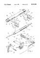
- FIG. 1is a perspective view of the components of the present invention
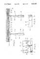
- FIG. 2is a perspective view of the first guide assembly for transverse alignment
- FIG. 3is a plan view, partially in section, of the first guide assembly
- FIG. 4is an end view, partially in section, taken along line 4--4 of FIG. 2;
- FIG. 5is a side elevation of the inner face of a clampplate of the first guide assembly
- FIG. 6is a section taken along line 6--6 of FIG. 5;
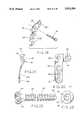
- FIG. 7is a perspective view of the depth gauge slide assembly of the present invention.
- FIG. 8is a foreshortened side elevation, partly in section, of the depth gauge slide assembly of the FIG. 7;
- FIG. 9is a section taken along line 9--9 of FIG. 7;
- FIG. 10is a section taken along line 10--10 of FIG. 7;
- FIG. 11is a detail of the scale face of the depth gauge slide assembly of FIG. 7;
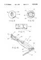
- FIG. 12is a perspective view of the osteotomy second guide assembly
- FIG. 13is a side elevation of the osteotomy second guide assembly
- FIG. 14is a end elevation of the guide body member of the second guide assembly
- FIG. 15is a section taken along line 15--15 of FIG. 13;
- FIG. 16is a perspective view of the external compressor assembly
- FIG. 17is a plan view of the compressor assembly of FIG. 16;
- FIG. 18is a detail of the compressor assembly
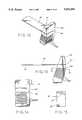
- FIG 19is a perspective view of the buttress plate with a fixation screw exploded therefrom;
- FIG. 20is a side elevation of the buttress plate
- FIG. 21is an end elevation of the buttress plate
- FIG. 22is a side elevation, partly in section, of a bone screw used with the present invention.
- FIG. 23is an end view of the bone screw of FIG. 22.
- FIGS. 24-31show the sequence of use of the components of the present invention as they would be utilized to perform an upper tibial osteotomy according to the subject method.
- FIG. 1The components of the present invention are shown in FIG. 1 and comprise a transverse alignment or first guide assembly 10, a depth gauge slide assembly 12, and an osteotomy second guide assembly 14, a compressor assembly 16, a buttress plate 18 and one or more bone screws such as bone screw 20.
- the detailed structure of each of these componentswill be discussed first and then their use in performing an upper tibial osteotomy will be described with reference to FIGS. 24 to 31.
- the transverse alignment or first guide assembly 10has an elongated cylindrical body member 22 having an axial bore 24 extending completely therethrough.
- the boreis intersected at each end by longitudinal slots 26, 28 with the slot 28 having a radial extension 30 (see FIG. 4) extending approximately a quarter of the way around the circumference of the body 22.
- a threaded shaft 32is mounted to extend through the bore 24 with knurled knobs 34, 36 held on opposite ends thereof by pins 38, 40, respectively.
- a pair of mirror image clamp arm assemblies 42, 44are formed by arms 46, 48 having integrally fixed on one end thereof internally threaded cylinders 50, 52 extending normal to the axis of the arms and receiving the threaded shaft 32 therein.
- the outer dimensions of the cylinders 50, 52are such as to allow free sliding movement in the bore 24.
- a clamp plate 54, 56is fixed on the free end of the respective arms 46, 48, with each plate having an inwardly directed, slightly profiled, clamp face 58, 60.
- Each clamp plateis provided with a guide bore 62, a plurality of bores 64, and a guide slot 66, which are parallel to the axis of the cylindrical body member 22 and normal to the axis of the respective arm 46, 48 and displaced therefrom.
- the guide bores 62 and guide slots 66are also axially aligned between the guide plates 54, 56.
- a plurality of gripping protuberances 68extend from the guide face 58, 60.
- the guide slot 66has an oblique end wall 67 which is provided to minimize contact between the end wall 67 and a saw blade, the use of which is explained hereafter.
- the depth gauge slide assembly 12is shown in FIGS. 7 through 11.
- This assemblyis formed by a generally cylindrical body 70 having a through-bore 72 with a cap 74 threaded on one end thereof.
- the cap 74has a axial bore 76 through which an elongated measuring arm 78 extends.
- the the arm 78is profiled at 80 to include a transversely extending lip 82 on the free end thereof.
- a scale arm 84extends from the opposite end of the bore 72 and has an axial bore 86 which receives therein the opposite end 88 of the measuring arm 78.
- the scale arm 84has a flattened surface 90 on which is inscribed a measuring scale (see FIG. 11).
- the measuring arm 78has a slight bend 79 in it forcing the scale against the side of the cylinder body (as shown in FIG.8). This creates a friction fit so that the arm and scale cannot move at random.
- the osteotomy guide assemblyis shown in FIGS. 12 to 15 and includes a body member 92 having a first slot 94 therein.
- a flat blade 96is fixed in the first slot extending therefrom.
- a plurality of guide slots 98are formed in the body 92 each slot 98 having parallel transverse axes and being offset from the first slot 94 by an angular displacement so that a cutting blade member passing through any of the slots 98 will intersect the flat blade 96 at approximately the same location 97 spaced from body 92 thereby defining wedge shapes of different angular dimensions.
- the slots 98have an oblique end wall 99 which is provided to minimize contact between the end wall 99 and the saw blade.
- the compressor assembly 16is shown in FIGS. 16 to 18 and includes arms 100, 102 pivotally attached intermediate their ends by pivot pin 104.
- First like ends 106, 108 of the arms 100, 102are provided with profiled bars 110, 112, respectively. These bars are shown generally as rods with slightly curved end portions for grippingly engaging the bone surface and holes in the buttress plate 18.
- the bone engaging arm 110is preferably slightly longer than the plate engaging arm 112.
- Spring 114is mounted between arms 100, 102 towards their second ends which are provided with a ratchet assembly 116 including fixed powl 118 on arm 102 and rack 120 pivotally attached to arm 100 by pin 122.
- the buttress plate 18is shown in FIGS. 19 to 21 and is generally an L-shaped member having a first arm 124, a second arm 126, and a plurality of through-bores 128. It will be appreciated from the perspective view in FIG. 19 and the end elevation in FIG. 20 that the buttress plate is not planar but is profiled to conform to the upper portion of a tibia.
- the plateis made of any of the known biocompatible metals.
- FIGS. 22 and 23show a bone screw 20 of the type used with the present invention.
- Each screw 20is formed from a biocompatible metal and has a threaded shank 130 with a self-tapping end 132 and a head 134 with a drive recess 136, in this case a hexagonal recess.
- FIG. 24shows a typical knee joint formed by a tibia 138, a fibula 140, a femur 142, and a patella 144.
- a tibia 138a fibula 140
- a femur 142a femur 142
- a patella 144a typical knee joint formed by a tibia 138, a fibula 140, a femur 142, and a patella 144.
- there is an angular offset 145 between the anatomic axes of the tibia and the femurIn the instance shown, which is a right leg, this angle is not of sufficient magnitude, for any one of a number of reasons, so that the mechanical axis does not pass substantially through the intersection of the anatomic axes at the joint.
- the jointis surgically exposed and the joint line indentified using tibial locating needles 137.
- the transverse alignment or first guide assembly 10is positioned mediolaterally on the upper tibia 138, as shown in FIG. 25, with the upper end of the assembly touching the tibial locating needles.
- the clamp arm 44can be swung to a position almost normal to the clamp arm 42, by virtue of the slot 30 in order to facilitate this mounting of the assembly on the tibia.
- the two clamp plates 54, 56are brought into engagement with opposite sides of the tibia by rotation of the knobs 34, 36 driving cylinders 50, 52 along the threaded shaft 32.
- the assemblyis stabilized by drills 19 inserted into the bone through holes 64.
- a transverse boreis drilled completely through the tibia using one of the guide holes 62.
- the depth gauge slide assembly 12is used, as shown in FIG. 26, to measure the width of the bone. With the body 70 pressed against the near side of the guide plate 54, the measuring arm 78 is passed completely through the tibia and hooked on the far side to obtain an accurate measurement as to the bone width by reading the scale 90. This is an important measurement since it is the desire not to completely sever the top of the tibia, as would be the case in preparation for a total knee replacement prosthesis.
- a cutting blade 146is then inserted through guide slot 66 to make a cut in the tibia to the depth chosen, which depth is less than that measured by the depth gauge slide assembly, see FIG. 27. It will be seen from FIG. 27 that the top of the tibia is not completely severed. The cutting blade 146 is removed and the first guide assembly 10 is also removed.
- the blade 96 of the osteotomy or second guide assembly 14is inserted into this first cut.
- This guide assembly 14is stabilized by placing it on the same drills as were used for the first guide with the blade fitting in the slot cut by the first guide as shown in FIG. 28.
- the cutting blade 146is then introduced through one of the slots 98 to cut a wedge-shaped section 148 from the tibia 138.
- the wedge-shaped section 148is removed, along with the osteotomy guide assembly 14.
- a buttress plate 18is fixed to the tibia with screws 20 entering the same holes used to stabilize the first guide assembly.
- the compressor assembly 16is then clamped against the bone and the buttress plate to apply pressure to close the osteotomy.
- a holecan be made in the tibia below the wedge-shaped section.
- One end of the bone engaging bar 110is inserted in the hole, in the bone and a corresponding end of the plate engaging bar 112 is placed in a hole in the buttress plate 18.
- Closing the osteotomyusually takes several minutes, and repeated tightening of the compressor assembly, as it is the object to plastically deform the bone rather than fracture the unsevered segment.
- a screwis placed to hold the plate 18 in place.
- the compressor assembly 16is removed and the buttress plate 18 is secured with additional screws to assure that the tibia will be held in proper alignment while new bone growth forms. It will be appreciated, from a comparison of FIGS. 24 and 31, that the present invention has accomplished the desired reestablishment of the proper angular relationship between the femur and the tibia.
Landscapes
- Health & Medical Sciences (AREA)
- Surgery (AREA)
- Life Sciences & Earth Sciences (AREA)
- Heart & Thoracic Surgery (AREA)
- Molecular Biology (AREA)
- Oral & Maxillofacial Surgery (AREA)
- Engineering & Computer Science (AREA)
- Biomedical Technology (AREA)
- Dentistry (AREA)
- Medical Informatics (AREA)
- Nuclear Medicine, Radiotherapy & Molecular Imaging (AREA)
- Animal Behavior & Ethology (AREA)
- General Health & Medical Sciences (AREA)
- Public Health (AREA)
- Veterinary Medicine (AREA)
- Orthopedic Medicine & Surgery (AREA)
- Surgical Instruments (AREA)
Abstract
Description
Claims (5)
Priority Applications (2)
| Application Number | Priority Date | Filing Date | Title |
|---|---|---|---|
| US07/407,244US5021056A (en) | 1989-09-14 | 1989-09-14 | Upper tibial osteotomy system |
| US07/691,394US5053039A (en) | 1989-09-14 | 1991-04-25 | Upper tibial osteotomy system |
Applications Claiming Priority (1)
| Application Number | Priority Date | Filing Date | Title |
|---|---|---|---|
| US07/407,244US5021056A (en) | 1989-09-14 | 1989-09-14 | Upper tibial osteotomy system |
Related Child Applications (1)
| Application Number | Title | Priority Date | Filing Date |
|---|---|---|---|
| US07/691,394DivisionUS5053039A (en) | 1989-09-14 | 1991-04-25 | Upper tibial osteotomy system |
Publications (1)
| Publication Number | Publication Date |
|---|---|
| US5021056Atrue US5021056A (en) | 1991-06-04 |
Family
ID=23611236
Family Applications (1)
| Application Number | Title | Priority Date | Filing Date |
|---|---|---|---|
| US07/407,244Expired - LifetimeUS5021056A (en) | 1989-09-14 | 1989-09-14 | Upper tibial osteotomy system |
Country Status (1)
| Country | Link |
|---|---|
| US (1) | US5021056A (en) |
Cited By (110)
| Publication number | Priority date | Publication date | Assignee | Title |
|---|---|---|---|---|
| EP0570187A1 (en)* | 1992-05-03 | 1993-11-18 | Technology Finance Corporation (Proprietary) Limited | Surgical instruments |
| FR2715557A1 (en)* | 1994-01-28 | 1995-08-04 | Lepine Groupe | Three part prosthetic ankle joint |
| USD363545S (en) | 1993-10-04 | 1995-10-24 | Zimmer, Inc. | Jaw portion of compression clamp forceps |
| FR2721195A1 (en)* | 1994-06-21 | 1995-12-22 | Jacques Afriat | Guide for fitting osteotomy plate |
| US5514143A (en)* | 1991-11-27 | 1996-05-07 | Apogee Medical Products, Inc. | Apparatus and method for use during surgery |
| US5540695A (en)* | 1994-02-18 | 1996-07-30 | Howmedica Inc. | Osteotomy cutting guide |
| WO1996024295A1 (en)* | 1995-02-07 | 1996-08-15 | Jenkins Joseph R Jr | Improved tibial osteotomy system |
| US5667512A (en)* | 1996-05-03 | 1997-09-16 | Metagen, Llc | Patellar resection guide |
| US5722978A (en)* | 1996-03-13 | 1998-03-03 | Jenkins, Jr.; Joseph Robert | Osteotomy system |
| US5817097A (en)* | 1995-08-03 | 1998-10-06 | Synvasive Technology, Inc. | Bone saw blade guide with magnet |
| US5853413A (en)* | 1997-04-18 | 1998-12-29 | Bristol-Myers Squibb Company | Wrist fusion plate |
| US5935128A (en)* | 1997-04-18 | 1999-08-10 | Bristol-Myers Squibb Co. | Orthopaedic template system including a joint locator |
| US5938664A (en)* | 1998-03-31 | 1999-08-17 | Zimmer, Inc. | Orthopaedic bone plate |
| US5980526A (en)* | 1997-02-12 | 1999-11-09 | Orthopaedic Innovations, Inc. | Wedge osteotomy device including a guide for controlling osteotomy depth |
| US6183475B1 (en) | 1998-12-18 | 2001-02-06 | Sulzer Orthopedics Inc. | Distal femoral osteotomy system and method |
| US20030028196A1 (en)* | 2000-01-14 | 2003-02-06 | Bonutti Peter M. | Method of performing surgery |
| US20030060827A1 (en)* | 2001-09-26 | 2003-03-27 | Coughln Michael John | Plate for fixing the bones of a joint, in particular a metatarso-phalangeal joint |
| US6602259B1 (en)* | 1995-11-02 | 2003-08-05 | Medidea, Llc | Bone cutting guides for use in the implantation of prosthetic joint components |
| US20040015173A1 (en)* | 2002-01-25 | 2004-01-22 | Irving John F. | Extramedullary fluoroscopic alignment guide |
| US6695848B2 (en)* | 1994-09-02 | 2004-02-24 | Hudson Surgical Design, Inc. | Methods for femoral and tibial resection |
| US6712825B2 (en) | 1998-10-02 | 2004-03-30 | Max Aebi | Spinal disc space distractor |
| US20040078042A1 (en)* | 1997-09-18 | 2004-04-22 | Masini Michael A. | Bone-conserving orthopedic instrumentation and appliances |
| US20040078043A1 (en)* | 1997-09-18 | 2004-04-22 | Masini Michael A. | Joint replacement methods and apparatus |
| US20040102775A1 (en)* | 2002-11-19 | 2004-05-27 | Huebner Randall J. | Bone plates with slots |
| US20040102776A1 (en)* | 2002-11-19 | 2004-05-27 | Huebner Randall J. | Bone plates with reference marks |
| US20040102777A1 (en)* | 2002-11-19 | 2004-05-27 | Huebner Randall J. | Deformable bone plates |
| US20040127901A1 (en)* | 2002-07-22 | 2004-07-01 | Huebner Randall J. | Bone fusion system |
| US20050085818A1 (en)* | 2003-10-17 | 2005-04-21 | Huebner Randall J. | Systems for distal radius fixation |
| US20060161163A1 (en)* | 2003-07-11 | 2006-07-20 | Konsei Shino | Instrument for reconstructing ligament and method of reconstructing ligament |
| US20060173458A1 (en)* | 2004-10-07 | 2006-08-03 | Micah Forstein | Bone fracture fixation system |
| JP2006519636A (en)* | 2003-02-12 | 2006-08-31 | 剛 村瀬 | Method, member, system and program for bone correction |
| US20070118146A1 (en)* | 2005-11-23 | 2007-05-24 | Stryker Trauma S.A. | Compression instrument |
| US20070270850A1 (en)* | 2006-04-28 | 2007-11-22 | Geissler William B | Osteotomy systems |
| US20080147075A1 (en)* | 2000-01-14 | 2008-06-19 | Peter M Bonutti | Minimally Invasive Surgical Systems and Methods |
| US20080195099A1 (en)* | 2007-02-13 | 2008-08-14 | The Brigham And Women's Hospital, Inc. | Osteotomy system |
| US20080195097A1 (en)* | 2005-04-25 | 2008-08-14 | University Of Maryland, Baltimore | Coronoid Process Fracture Fixator |
| US7537596B2 (en) | 2003-06-20 | 2009-05-26 | Acumed Llc | Bone plates with intraoperatively tapped apertures |
| US7635365B2 (en) | 2003-08-28 | 2009-12-22 | Ellis Thomas J | Bone plates |
| US7708741B1 (en) | 2001-08-28 | 2010-05-04 | Marctec, Llc | Method of preparing bones for knee replacement surgery |
| USD616095S1 (en)* | 2009-02-24 | 2010-05-18 | Eidosmed Llc | Handheld surgical depth instrument with cylindrical body |
| US7717945B2 (en) | 2002-07-22 | 2010-05-18 | Acumed Llc | Orthopedic systems |
| US20100168799A1 (en)* | 2008-12-29 | 2010-07-01 | Schumer Evan D | Ulnar osteotomy plate including increased compression |
| US20100217328A1 (en)* | 2009-02-24 | 2010-08-26 | Osteomed L.P. | Multiple Bone Fusion Plate |
| US7815645B2 (en) | 2004-01-14 | 2010-10-19 | Hudson Surgical Design, Inc. | Methods and apparatus for pinplasty bone resection |
| US20100274293A1 (en)* | 2009-04-28 | 2010-10-28 | Osteomed L.P. | Bone Plate with a Transfixation Screw Hole |
| US7857814B2 (en) | 2004-01-14 | 2010-12-28 | Hudson Surgical Design, Inc. | Methods and apparatus for minimally invasive arthroplasty |
| US7935151B2 (en) | 2001-03-05 | 2011-05-03 | Hudson Surgical Design, Inc. | Femoral prosthetic implant |
| US7959635B1 (en) | 2000-01-14 | 2011-06-14 | Marctec, Llc. | Limited incision total joint replacement methods |
| US8021368B2 (en) | 2004-01-14 | 2011-09-20 | Hudson Surgical Design, Inc. | Methods and apparatus for improved cutting tools for resection |
| US8114083B2 (en) | 2004-01-14 | 2012-02-14 | Hudson Surgical Design, Inc. | Methods and apparatus for improved drilling and milling tools for resection |
| US8177819B2 (en) | 2004-04-22 | 2012-05-15 | Acumed Llc | Expanded fixation of bones |
| US8287545B2 (en) | 2004-01-14 | 2012-10-16 | Hudson Surgical Design, Inc. | Methods and apparatus for enhanced retention of prosthetic implants |
| WO2012139114A3 (en)* | 2011-04-08 | 2013-01-03 | Paragon 28, Inc. | Bone implants and cutting apparatuses and methods |
| US8568417B2 (en) | 2009-12-18 | 2013-10-29 | Charles River Engineering Solutions And Technologies, Llc | Articulating tool and methods of using |
| US8603095B2 (en) | 1994-09-02 | 2013-12-10 | Puget Bio Ventures LLC | Apparatuses for femoral and tibial resection |
| US20130331845A1 (en)* | 2009-01-23 | 2013-12-12 | DePuy Synthes Products, LLC | Jig and Saw Guides for Use in Osteotomies |
| US8740906B2 (en) | 2004-01-14 | 2014-06-03 | Hudson Surgical Design, Inc. | Method and apparatus for wireplasty bone resection |
| US8747439B2 (en) | 2000-03-13 | 2014-06-10 | P Tech, Llc | Method of using ultrasonic vibration to secure body tissue with fastening element |
| US8808329B2 (en) | 1998-02-06 | 2014-08-19 | Bonutti Skeletal Innovations Llc | Apparatus and method for securing a portion of a body |
| US8814902B2 (en) | 2000-05-03 | 2014-08-26 | Bonutti Skeletal Innovations Llc | Method of securing body tissue |
| WO2014140395A1 (en)* | 2013-03-14 | 2014-09-18 | Mozo-Grau, S.L. | Osteotomy marker |
| US8845687B2 (en) | 1996-08-19 | 2014-09-30 | Bonutti Skeletal Innovations Llc | Anchor for securing a suture |
| US8845699B2 (en) | 1999-08-09 | 2014-09-30 | Bonutti Skeletal Innovations Llc | Method of securing tissue |
| US8858602B2 (en) | 2011-02-01 | 2014-10-14 | Nextremity Solutions, Inc. | Bone defect repair device and method |
| WO2015003284A2 (en) | 2013-07-12 | 2015-01-15 | RIOS Medical AG | Surgical perforation guide |
| US20150297361A1 (en)* | 2014-04-18 | 2015-10-22 | Biomet Manufacturing, Llc | Orthopaedic instrument for securing a bone |
| US9237910B2 (en) | 2012-01-26 | 2016-01-19 | Acute Innovations Llc | Clip for rib stabilization |
| WO2016033497A1 (en)* | 2014-08-28 | 2016-03-03 | Nextremity Solutions, Inc. | Proximal bunion resection guides and plates and methods of use |
| US9387020B2 (en) | 2011-01-10 | 2016-07-12 | Ascension Orthopedics, Inc. | Bone plate system for repair of proximal humeral fracture |
| US9622805B2 (en) | 2015-08-14 | 2017-04-18 | Treace Medical Concepts, Inc. | Bone positioning and preparing guide systems and methods |
| US9687250B2 (en) | 2015-01-07 | 2017-06-27 | Treace Medical Concepts, Inc. | Bone cutting guide systems and methods |
| US9770238B2 (en) | 2001-12-03 | 2017-09-26 | P Tech, Llc | Magnetic positioning apparatus |
| US9770272B2 (en) | 2012-12-12 | 2017-09-26 | Wright Medical Technology, Inc. | Orthopedic compression/distraction device |
| US9775657B2 (en) | 2011-09-30 | 2017-10-03 | Acute Innovations Llc | Bone fixation system with opposed mounting portions |
| US10159499B2 (en) | 2011-04-08 | 2018-12-25 | Paragon 26, Inc. | Bone implants and cutting apparatuses and methods |
| US10342590B2 (en) | 2015-08-14 | 2019-07-09 | Treace Medical Concepts, Inc. | Tarsal-metatarsal joint procedure utilizing fulcrum |
| US10512470B1 (en) | 2016-08-26 | 2019-12-24 | Treace Medical Concepts, Inc. | Osteotomy procedure for correcting bone misalignment |
| US10524808B1 (en) | 2016-11-11 | 2020-01-07 | Treace Medical Concepts, Inc. | Devices and techniques for performing an osteotomy procedure on a first metatarsal to correct a bone misalignment |
| US10555757B2 (en) | 2014-07-15 | 2020-02-11 | Treace Medical Concepts, Inc. | Bone positioning and cutting system and method |
| US10575862B2 (en) | 2015-09-18 | 2020-03-03 | Treace Medical Concepts, Inc. | Joint spacer systems and methods |
| US10653467B2 (en) | 2015-05-06 | 2020-05-19 | Treace Medical Concepts, Inc. | Intra-osseous plate system and method |
| US10849631B2 (en) | 2015-02-18 | 2020-12-01 | Treace Medical Concepts, Inc. | Pivotable bone cutting guide useful for bone realignment and compression techniques |
| US10849663B2 (en) | 2015-07-14 | 2020-12-01 | Treace Medical Concepts, Inc. | Bone cutting guide systems and methods |
| US10874446B2 (en) | 2015-07-14 | 2020-12-29 | Treace Medical Concepts, Inc. | Bone positioning guide |
| US10939939B1 (en) | 2017-02-26 | 2021-03-09 | Treace Medical Concepts, Inc. | Fulcrum for tarsal-metatarsal joint procedure |
| US20210267769A1 (en)* | 2018-06-25 | 2021-09-02 | Conmed Corporation | Ligament revision system |
| US11278337B2 (en) | 2015-08-14 | 2022-03-22 | Treace Medical Concepts, Inc. | Tarsal-metatarsal joint procedure utilizing fulcrum |
| US11583323B2 (en) | 2018-07-12 | 2023-02-21 | Treace Medical Concepts, Inc. | Multi-diameter bone pin for installing and aligning bone fixation plate while minimizing bone damage |
| US11596443B2 (en) | 2018-07-11 | 2023-03-07 | Treace Medical Concepts, Inc. | Compressor-distractor for angularly realigning bone portions |
| US11607250B2 (en) | 2019-02-13 | 2023-03-21 | Treace Medical Concepts, Inc. | Tarsal-metatarsal joint procedure utilizing compressor-distractor and instrument providing sliding surface |
| US11622797B2 (en) | 2020-01-31 | 2023-04-11 | Treace Medical Concepts, Inc. | Metatarsophalangeal joint preparation and metatarsal realignment for fusion |
| US11627954B2 (en) | 2019-08-07 | 2023-04-18 | Treace Medical Concepts, Inc. | Bi-planar instrument for bone cutting and joint realignment procedure |
| USD1011524S1 (en) | 2022-02-23 | 2024-01-16 | Treace Medical Concepts, Inc. | Compressor-distractor for the foot |
| US11890039B1 (en) | 2019-09-13 | 2024-02-06 | Treace Medical Concepts, Inc. | Multi-diameter K-wire for orthopedic applications |
| US11889998B1 (en) | 2019-09-12 | 2024-02-06 | Treace Medical Concepts, Inc. | Surgical pin positioning lock |
| US11931106B2 (en) | 2019-09-13 | 2024-03-19 | Treace Medical Concepts, Inc. | Patient-specific surgical methods and instrumentation |
| US11986251B2 (en) | 2019-09-13 | 2024-05-21 | Treace Medical Concepts, Inc. | Patient-specific osteotomy instrumentation |
| US12004789B2 (en) | 2020-05-19 | 2024-06-11 | Treace Medical Concepts, Inc. | Devices and techniques for treating metatarsus adductus |
| WO2024134716A1 (en)* | 2022-12-19 | 2024-06-27 | オリンパステルモバイオマテリアル株式会社 | Guide device |
| USD1051382S1 (en) | 2022-02-23 | 2024-11-12 | Treace Medical Concepts, Inc. | Lesser metatarsal cut guide |
| US12161371B2 (en) | 2021-01-18 | 2024-12-10 | Treace Medical Concepts, Inc. | Contoured bone plate with locking screw for bone compression, particularly across a tarsometatarsal joint |
| USD1057155S1 (en) | 2022-02-23 | 2025-01-07 | Treace Medical Concepts, Inc. | Lesser metatarsal cut guide with parallel cut faces |
| US12193683B2 (en) | 2021-05-20 | 2025-01-14 | Treace Medical Concepts, Inc. | Cut guide with integrated joint realignment features |
| USD1068077S1 (en) | 2023-02-08 | 2025-03-25 | Treace Medical Concepts, Inc. | Orthopedic rasp for preparing an intercuneiform joint |
| USD1068078S1 (en) | 2023-02-08 | 2025-03-25 | Treace Medical Concepts, Inc. | Handle for an orthopedic instrument |
| US12285197B2 (en) | 2008-10-10 | 2025-04-29 | Acumed Llc | Bone fixation system with opposed mounting portions |
| USD1075012S1 (en) | 2022-02-23 | 2025-05-13 | Treace Medical Concepts, Inc. | Metatarsal lateral release instrument |
| US12310603B2 (en) | 2021-02-18 | 2025-05-27 | Treace Medical Concepts, Inc. | System and technique for metatarsal realignment with reduced incision length |
| USD1079011S1 (en) | 2022-02-23 | 2025-06-10 | Treace Medical Concepts, Inc. | Metatarsal cut guide with parallel cut faces |
| US12440250B2 (en) | 2024-02-05 | 2025-10-14 | Treace Medical Concepts, Inc. | Multi-diameter K-wire for orthopedic applications |
Citations (9)
| Publication number | Priority date | Publication date | Assignee | Title |
|---|---|---|---|---|
| US4335715A (en)* | 1980-06-20 | 1982-06-22 | Kirkley William H | Osteotomy guide |
| US4501268A (en)* | 1981-08-20 | 1985-02-26 | Comparetto John E | Bone wedge guidance system |
| US4509511A (en)* | 1983-06-30 | 1985-04-09 | Neufeld John A | Method and apparatus for corrective osteotomy |
| US4565191A (en)* | 1984-01-12 | 1986-01-21 | Slocum D Barclay | Apparatus and method for performing cuneiform osteotomy |
| US4627425A (en)* | 1983-09-28 | 1986-12-09 | Reese H William | Osteotomy appliances and method |
| US4632102A (en)* | 1981-08-20 | 1986-12-30 | Comparetto John E | Bone wedge osteotomy method |
| US4736737A (en)* | 1986-03-31 | 1988-04-12 | William Fargie | Tibial cutting jig |
| US4750481A (en)* | 1984-04-16 | 1988-06-14 | Reese H William | Osteotomy appliances and method |
| US4757810A (en)* | 1986-07-23 | 1988-07-19 | Reese Hewitt W | Osteotomy apparatus and method |
- 1989
- 1989-09-14USUS07/407,244patent/US5021056A/ennot_activeExpired - Lifetime
Patent Citations (9)
| Publication number | Priority date | Publication date | Assignee | Title |
|---|---|---|---|---|
| US4335715A (en)* | 1980-06-20 | 1982-06-22 | Kirkley William H | Osteotomy guide |
| US4501268A (en)* | 1981-08-20 | 1985-02-26 | Comparetto John E | Bone wedge guidance system |
| US4632102A (en)* | 1981-08-20 | 1986-12-30 | Comparetto John E | Bone wedge osteotomy method |
| US4509511A (en)* | 1983-06-30 | 1985-04-09 | Neufeld John A | Method and apparatus for corrective osteotomy |
| US4627425A (en)* | 1983-09-28 | 1986-12-09 | Reese H William | Osteotomy appliances and method |
| US4565191A (en)* | 1984-01-12 | 1986-01-21 | Slocum D Barclay | Apparatus and method for performing cuneiform osteotomy |
| US4750481A (en)* | 1984-04-16 | 1988-06-14 | Reese H William | Osteotomy appliances and method |
| US4736737A (en)* | 1986-03-31 | 1988-04-12 | William Fargie | Tibial cutting jig |
| US4757810A (en)* | 1986-07-23 | 1988-07-19 | Reese Hewitt W | Osteotomy apparatus and method |
Cited By (241)
| Publication number | Priority date | Publication date | Assignee | Title |
|---|---|---|---|---|
| US5514143A (en)* | 1991-11-27 | 1996-05-07 | Apogee Medical Products, Inc. | Apparatus and method for use during surgery |
| EP0570187A1 (en)* | 1992-05-03 | 1993-11-18 | Technology Finance Corporation (Proprietary) Limited | Surgical instruments |
| USD363545S (en) | 1993-10-04 | 1995-10-24 | Zimmer, Inc. | Jaw portion of compression clamp forceps |
| FR2715557A1 (en)* | 1994-01-28 | 1995-08-04 | Lepine Groupe | Three part prosthetic ankle joint |
| US5540695A (en)* | 1994-02-18 | 1996-07-30 | Howmedica Inc. | Osteotomy cutting guide |
| FR2721195A1 (en)* | 1994-06-21 | 1995-12-22 | Jacques Afriat | Guide for fitting osteotomy plate |
| US9066804B2 (en) | 1994-09-02 | 2015-06-30 | Puget Bioventures Llc | Method and apparatus for femoral and tibial resection |
| US7967822B2 (en) | 1994-09-02 | 2011-06-28 | Hudson Surgical Design, Inc. | Methods and apparatus for orthopedic implants |
| US7344541B2 (en)* | 1994-09-02 | 2008-03-18 | Hudson Surgical Design, Inc. | Methods and apparatus for femoral and tibial resection |
| US6695848B2 (en)* | 1994-09-02 | 2004-02-24 | Hudson Surgical Design, Inc. | Methods for femoral and tibial resection |
| US8603095B2 (en) | 1994-09-02 | 2013-12-10 | Puget Bio Ventures LLC | Apparatuses for femoral and tibial resection |
| US20050055028A1 (en)* | 1994-09-02 | 2005-03-10 | Hudson Surgical Design, Inc. | Methods and apparatus for femoral and tibial resection |
| US20050149038A1 (en)* | 1994-09-02 | 2005-07-07 | Hudson Surgical, Inc. | Methods and apparatus for orthopedic implant preparation systems |
| US5613969A (en)* | 1995-02-07 | 1997-03-25 | Jenkins, Jr.; Joseph R. | Tibial osteotomy system |
| WO1996024295A1 (en)* | 1995-02-07 | 1996-08-15 | Jenkins Joseph R Jr | Improved tibial osteotomy system |
| US5817097A (en)* | 1995-08-03 | 1998-10-06 | Synvasive Technology, Inc. | Bone saw blade guide with magnet |
| US6602259B1 (en)* | 1995-11-02 | 2003-08-05 | Medidea, Llc | Bone cutting guides for use in the implantation of prosthetic joint components |
| US5722978A (en)* | 1996-03-13 | 1998-03-03 | Jenkins, Jr.; Joseph Robert | Osteotomy system |
| US5667512A (en)* | 1996-05-03 | 1997-09-16 | Metagen, Llc | Patellar resection guide |
| US8845687B2 (en) | 1996-08-19 | 2014-09-30 | Bonutti Skeletal Innovations Llc | Anchor for securing a suture |
| US5980526A (en)* | 1997-02-12 | 1999-11-09 | Orthopaedic Innovations, Inc. | Wedge osteotomy device including a guide for controlling osteotomy depth |
| US5935128A (en)* | 1997-04-18 | 1999-08-10 | Bristol-Myers Squibb Co. | Orthopaedic template system including a joint locator |
| US5853413A (en)* | 1997-04-18 | 1998-12-29 | Bristol-Myers Squibb Company | Wrist fusion plate |
| US20040078043A1 (en)* | 1997-09-18 | 2004-04-22 | Masini Michael A. | Joint replacement methods and apparatus |
| US20040078042A1 (en)* | 1997-09-18 | 2004-04-22 | Masini Michael A. | Bone-conserving orthopedic instrumentation and appliances |
| US7419491B2 (en) | 1997-09-18 | 2008-09-02 | Medidea, Llc | Bone-conserving orthopedic instrumentation and appliances |
| US8808329B2 (en) | 1998-02-06 | 2014-08-19 | Bonutti Skeletal Innovations Llc | Apparatus and method for securing a portion of a body |
| US20070162015A1 (en)* | 1998-03-31 | 2007-07-12 | Zimmer Technology, Inc. | Orthopaedic bone plate |
| US7846189B2 (en) | 1998-03-31 | 2010-12-07 | Zimmer, Inc. | Orthopaedic bone plate |
| US6355042B2 (en) | 1998-03-31 | 2002-03-12 | Bristol-Myers Squibb Company | Orthopaedic bone plate |
| US5938664A (en)* | 1998-03-31 | 1999-08-17 | Zimmer, Inc. | Orthopaedic bone plate |
| US6712825B2 (en) | 1998-10-02 | 2004-03-30 | Max Aebi | Spinal disc space distractor |
| US20050177173A1 (en)* | 1998-10-02 | 2005-08-11 | Max Aebi | Spinal disc space distractor |
| US6183475B1 (en) | 1998-12-18 | 2001-02-06 | Sulzer Orthopedics Inc. | Distal femoral osteotomy system and method |
| US8845699B2 (en) | 1999-08-09 | 2014-09-30 | Bonutti Skeletal Innovations Llc | Method of securing tissue |
| US8133229B1 (en) | 2000-01-14 | 2012-03-13 | Marctec, Llc. | Knee arthroplasty method |
| US7806897B1 (en) | 2000-01-14 | 2010-10-05 | Marctec, Llc | Knee arthroplasty and preservation of the quadriceps mechanism |
| US7104996B2 (en) | 2000-01-14 | 2006-09-12 | Marctec. Llc | Method of performing surgery |
| US20030028196A1 (en)* | 2000-01-14 | 2003-02-06 | Bonutti Peter M. | Method of performing surgery |
| US8632552B2 (en) | 2000-01-14 | 2014-01-21 | Bonutti Skeletal Innovations Llc | Method of preparing a femur and tibia in knee arthroplasty |
| US9101443B2 (en) | 2000-01-14 | 2015-08-11 | Bonutti Skeletal Innovations Llc | Methods for robotic arthroplasty |
| US7837736B2 (en) | 2000-01-14 | 2010-11-23 | Marctec, Llc | Minimally invasive surgical systems and methods |
| US7806896B1 (en) | 2000-01-14 | 2010-10-05 | Marctec, Llc | Knee arthroplasty method |
| US8425522B2 (en) | 2000-01-14 | 2013-04-23 | Bonutti Skeletal Innovations Llc | Joint replacement method |
| US9192459B2 (en) | 2000-01-14 | 2015-11-24 | Bonutti Skeletal Innovations Llc | Method of performing total knee arthroplasty |
| US8784495B2 (en) | 2000-01-14 | 2014-07-22 | Bonutti Skeletal Innovations Llc | Segmental knee arthroplasty |
| US7892236B1 (en) | 2000-01-14 | 2011-02-22 | Marctec, Llc | System and method for total joint replacement |
| US9795394B2 (en) | 2000-01-14 | 2017-10-24 | Bonutti Skeletal Innovations Llc | Method for placing implant using robotic system |
| US7828852B2 (en) | 2000-01-14 | 2010-11-09 | Marctec, Llc. | Inlaid articular implant |
| US7708740B1 (en) | 2000-01-14 | 2010-05-04 | Marctec, Llc | Method for total knee arthroplasty and resecting bone in situ |
| US7510557B1 (en) | 2000-01-14 | 2009-03-31 | Bonutti Research Inc. | Cutting guide |
| US20080147075A1 (en)* | 2000-01-14 | 2008-06-19 | Peter M Bonutti | Minimally Invasive Surgical Systems and Methods |
| US7959635B1 (en) | 2000-01-14 | 2011-06-14 | Marctec, Llc. | Limited incision total joint replacement methods |
| US7749229B1 (en) | 2000-01-14 | 2010-07-06 | Marctec, Llc | Total knee arthroplasty through shortened incision |
| US7615054B1 (en) | 2000-01-14 | 2009-11-10 | Martec, LLC | Bicompartmental knee implant and method |
| US7931690B1 (en) | 2000-01-14 | 2011-04-26 | Marctec, Llc | Method of resurfacing an articular surface of a bone |
| US7635390B1 (en) | 2000-01-14 | 2009-12-22 | Marctec, Llc | Joint replacement component having a modular articulating surface |
| US8747439B2 (en) | 2000-03-13 | 2014-06-10 | P Tech, Llc | Method of using ultrasonic vibration to secure body tissue with fastening element |
| US8814902B2 (en) | 2000-05-03 | 2014-08-26 | Bonutti Skeletal Innovations Llc | Method of securing body tissue |
| US9192391B2 (en) | 2001-03-05 | 2015-11-24 | Puget Bioventures Llc | Method for minimally invasive total knee arthroplasty |
| US7935151B2 (en) | 2001-03-05 | 2011-05-03 | Hudson Surgical Design, Inc. | Femoral prosthetic implant |
| US8062377B2 (en) | 2001-03-05 | 2011-11-22 | Hudson Surgical Design, Inc. | Methods and apparatus for knee arthroplasty |
| US9421022B2 (en) | 2001-03-05 | 2016-08-23 | Puget Bioventures Llc | Method and apparatus for total knee arthroplasty |
| US8088167B2 (en) | 2001-03-05 | 2012-01-03 | Hudson Surgical Design, Inc. | Femoral prosthetic implant |
| US8430932B2 (en) | 2001-03-05 | 2013-04-30 | Puget Bio Ventures LLC | Femoral prosthetic implant |
| US7708741B1 (en) | 2001-08-28 | 2010-05-04 | Marctec, Llc | Method of preparing bones for knee replacement surgery |
| US10470780B2 (en) | 2001-08-28 | 2019-11-12 | Bonutti Skeletal Innovations Llc | Systems and methods for ligament balancing in robotic surgery |
| US9763683B2 (en) | 2001-08-28 | 2017-09-19 | Bonutti Skeletal Innovations Llc | Method for performing surgical procedures using optical cutting guides |
| US10231739B1 (en) | 2001-08-28 | 2019-03-19 | Bonutti Skeletal Innovations Llc | System and method for robotic surgery |
| US8623030B2 (en) | 2001-08-28 | 2014-01-07 | Bonutti Skeletal Innovations Llc | Robotic arthroplasty system including navigation |
| US9060797B2 (en) | 2001-08-28 | 2015-06-23 | Bonutti Skeletal Innovations Llc | Method of preparing a femur and tibia in knee arthroplasty |
| US8641726B2 (en) | 2001-08-28 | 2014-02-04 | Bonutti Skeletal Innovations Llc | Method for robotic arthroplasty using navigation |
| US8858557B2 (en) | 2001-08-28 | 2014-10-14 | Bonutti Skeletal Innovations Llc | Method of preparing a femur and tibia in knee arthroplasty |
| US8834490B2 (en) | 2001-08-28 | 2014-09-16 | Bonutti Skeletal Innovations Llc | Method for robotic arthroplasty using navigation |
| US10321918B2 (en) | 2001-08-28 | 2019-06-18 | Bonutti Skeletal Innovations Llc | Methods for robotic surgery using a cannula |
| US8840629B2 (en) | 2001-08-28 | 2014-09-23 | Bonutti Skeletal Innovations Llc | Robotic arthroplasty system including navigation |
| US7491220B2 (en)* | 2001-09-26 | 2009-02-17 | Newdeal S.A. | Plate for fixing the bones of a joint, in particular a metatarso-phalangeal joint |
| US20030060827A1 (en)* | 2001-09-26 | 2003-03-27 | Coughln Michael John | Plate for fixing the bones of a joint, in particular a metatarso-phalangeal joint |
| US9770238B2 (en) | 2001-12-03 | 2017-09-26 | P Tech, Llc | Magnetic positioning apparatus |
| US20040015173A1 (en)* | 2002-01-25 | 2004-01-22 | Irving John F. | Extramedullary fluoroscopic alignment guide |
| US20060235420A1 (en)* | 2002-01-25 | 2006-10-19 | Depuy Products, Inc. | Extramedullary fluoroscopic alignment guide |
| US7083624B2 (en)* | 2002-01-25 | 2006-08-01 | Depuy Products, Inc. | Extramedullary fluoroscopic alignment guide |
| US7763027B2 (en) | 2002-01-25 | 2010-07-27 | Depuy Products, Inc. | Extramedullary fluoroscopic alignment guide |
| US7537603B2 (en) | 2002-07-22 | 2009-05-26 | Acumed Llc | Bone fusion system |
| US7717945B2 (en) | 2002-07-22 | 2010-05-18 | Acumed Llc | Orthopedic systems |
| US20040127901A1 (en)* | 2002-07-22 | 2004-07-01 | Huebner Randall J. | Bone fusion system |
| US7189237B2 (en) | 2002-11-19 | 2007-03-13 | Acumed Llc | Deformable bone plates |
| US20040102775A1 (en)* | 2002-11-19 | 2004-05-27 | Huebner Randall J. | Bone plates with slots |
| US20040102776A1 (en)* | 2002-11-19 | 2004-05-27 | Huebner Randall J. | Bone plates with reference marks |
| US7537604B2 (en) | 2002-11-19 | 2009-05-26 | Acumed Llc | Bone plates with slots |
| US20040102777A1 (en)* | 2002-11-19 | 2004-05-27 | Huebner Randall J. | Deformable bone plates |
| US7326212B2 (en) | 2002-11-19 | 2008-02-05 | Acumed Llc | Bone plates with reference marks |
| JP2006519636A (en)* | 2003-02-12 | 2006-08-31 | 剛 村瀬 | Method, member, system and program for bone correction |
| EP1624812B1 (en)* | 2003-02-12 | 2015-04-15 | Tsuyoshi Murase | Members, apparatus and program for bone correction |
| US7537596B2 (en) | 2003-06-20 | 2009-05-26 | Acumed Llc | Bone plates with intraoperatively tapped apertures |
| US20060161163A1 (en)* | 2003-07-11 | 2006-07-20 | Konsei Shino | Instrument for reconstructing ligament and method of reconstructing ligament |
| US7695501B2 (en) | 2003-08-28 | 2010-04-13 | Ellis Thomas J | Bone fixation system |
| US7635365B2 (en) | 2003-08-28 | 2009-12-22 | Ellis Thomas J | Bone plates |
| US8632573B2 (en) | 2003-08-28 | 2014-01-21 | Thomas J. Ellis | Bone fixation system |
| US20050085818A1 (en)* | 2003-10-17 | 2005-04-21 | Huebner Randall J. | Systems for distal radius fixation |
| US8021368B2 (en) | 2004-01-14 | 2011-09-20 | Hudson Surgical Design, Inc. | Methods and apparatus for improved cutting tools for resection |
| US8298238B2 (en) | 2004-01-14 | 2012-10-30 | Hudson Surgical Design, Inc. | Methods and apparatus for pivotable guide surfaces for arthroplasty |
| US7815645B2 (en) | 2004-01-14 | 2010-10-19 | Hudson Surgical Design, Inc. | Methods and apparatus for pinplasty bone resection |
| US9814539B2 (en) | 2004-01-14 | 2017-11-14 | Puget Bioventures Llc | Methods and apparatus for conformable prosthetic implants |
| US8740906B2 (en) | 2004-01-14 | 2014-06-03 | Hudson Surgical Design, Inc. | Method and apparatus for wireplasty bone resection |
| US7857814B2 (en) | 2004-01-14 | 2010-12-28 | Hudson Surgical Design, Inc. | Methods and apparatus for minimally invasive arthroplasty |
| US8114083B2 (en) | 2004-01-14 | 2012-02-14 | Hudson Surgical Design, Inc. | Methods and apparatus for improved drilling and milling tools for resection |
| US8287545B2 (en) | 2004-01-14 | 2012-10-16 | Hudson Surgical Design, Inc. | Methods and apparatus for enhanced retention of prosthetic implants |
| US8353914B2 (en) | 2004-02-02 | 2013-01-15 | Hudson Surgical Design, Inc. | Methods and apparatus for improved profile based resection |
| US8177819B2 (en) | 2004-04-22 | 2012-05-15 | Acumed Llc | Expanded fixation of bones |
| US20060173458A1 (en)* | 2004-10-07 | 2006-08-03 | Micah Forstein | Bone fracture fixation system |
| US20090312760A1 (en)* | 2004-10-07 | 2009-12-17 | Zimmer, Inc. | Bone fracture fixation system |
| US8740905B2 (en) | 2004-10-07 | 2014-06-03 | Zimmer, Inc. | Bone fracture fixation system |
| US20080195097A1 (en)* | 2005-04-25 | 2008-08-14 | University Of Maryland, Baltimore | Coronoid Process Fracture Fixator |
| US7967825B2 (en)* | 2005-04-25 | 2011-06-28 | University Of Maryland, Baltimore | Coronoid process fracture fixator |
| US20070118146A1 (en)* | 2005-11-23 | 2007-05-24 | Stryker Trauma S.A. | Compression instrument |
| US7704257B2 (en)* | 2005-11-23 | 2010-04-27 | Stryker Trauma S.A. | Compression instrument |
| US8652142B2 (en) | 2006-04-28 | 2014-02-18 | Acumed Llc | Osteotomy systems |
| US20070270850A1 (en)* | 2006-04-28 | 2007-11-22 | Geissler William B | Osteotomy systems |
| US20080195099A1 (en)* | 2007-02-13 | 2008-08-14 | The Brigham And Women's Hospital, Inc. | Osteotomy system |
| US11083504B2 (en) | 2008-10-10 | 2021-08-10 | Acumed Llc | Bone fixation system with opposed mounting portions |
| US11911083B2 (en) | 2008-10-10 | 2024-02-27 | Acumed Llc | Bone fixation system with opposed mounting portions |
| US12285197B2 (en) | 2008-10-10 | 2025-04-29 | Acumed Llc | Bone fixation system with opposed mounting portions |
| US9808297B2 (en) | 2008-10-10 | 2017-11-07 | Acute Innovations Llc | Bone fixation system with opposed mounting portions |
| US20100168799A1 (en)* | 2008-12-29 | 2010-07-01 | Schumer Evan D | Ulnar osteotomy plate including increased compression |
| US20130331845A1 (en)* | 2009-01-23 | 2013-12-12 | DePuy Synthes Products, LLC | Jig and Saw Guides for Use in Osteotomies |
| US9375220B2 (en)* | 2009-01-23 | 2016-06-28 | DePuy Synthes Products, Inc. | Jig and saw guides for use in osteotomies |
| US8246664B2 (en) | 2009-02-24 | 2012-08-21 | Osteomed Llc | Multiple bone fusion plate |
| USD616095S1 (en)* | 2009-02-24 | 2010-05-18 | Eidosmed Llc | Handheld surgical depth instrument with cylindrical body |
| US20100217328A1 (en)* | 2009-02-24 | 2010-08-26 | Osteomed L.P. | Multiple Bone Fusion Plate |
| US10245085B2 (en) | 2009-04-28 | 2019-04-02 | Osteomed Llc | Bone plate with a transfixation screw hole |
| US9351776B2 (en) | 2009-04-28 | 2016-05-31 | Osteomed Llc | Bone plate with a transfixation screw hole |
| US20100274293A1 (en)* | 2009-04-28 | 2010-10-28 | Osteomed L.P. | Bone Plate with a Transfixation Screw Hole |
| US9763716B2 (en) | 2009-04-28 | 2017-09-19 | Osteomed Llc | Bone plate with a transfixation screw hole |
| US8529608B2 (en) | 2009-04-28 | 2013-09-10 | Osteomed Llc | Bone plate with a transfixation screw hole |
| US11033306B2 (en) | 2009-12-18 | 2021-06-15 | Charles River Engineering Solutions And Technologies, Llc | Articulating tool and methods of using |
| US9924986B2 (en) | 2009-12-18 | 2018-03-27 | Charles River Engineering Solutions And Technologies, Llc | Articulating tool and methods of using |
| US8568417B2 (en) | 2009-12-18 | 2013-10-29 | Charles River Engineering Solutions And Technologies, Llc | Articulating tool and methods of using |
| US9387020B2 (en) | 2011-01-10 | 2016-07-12 | Ascension Orthopedics, Inc. | Bone plate system for repair of proximal humeral fracture |
| US8858602B2 (en) | 2011-02-01 | 2014-10-14 | Nextremity Solutions, Inc. | Bone defect repair device and method |
| US10064631B2 (en) | 2011-04-08 | 2018-09-04 | Paragon 28, Inc. | Bone implants and cutting apparatuses and methods |
| US10159499B2 (en) | 2011-04-08 | 2018-12-25 | Paragon 26, Inc. | Bone implants and cutting apparatuses and methods |
| WO2012139114A3 (en)* | 2011-04-08 | 2013-01-03 | Paragon 28, Inc. | Bone implants and cutting apparatuses and methods |
| US9848893B2 (en) | 2011-04-08 | 2017-12-26 | Paragon 28, Inc. | Bone implants and cutting apparatuses and methods |
| US9452057B2 (en) | 2011-04-08 | 2016-09-27 | Paragon 28, Inc. | Bone implants and cutting apparatuses and methods |
| US9775657B2 (en) | 2011-09-30 | 2017-10-03 | Acute Innovations Llc | Bone fixation system with opposed mounting portions |
| US9237910B2 (en) | 2012-01-26 | 2016-01-19 | Acute Innovations Llc | Clip for rib stabilization |
| US10631900B2 (en) | 2012-12-12 | 2020-04-28 | Wright Medical Technology, Inc. | Orthopedic compression/distraction device |
| US9770272B2 (en) | 2012-12-12 | 2017-09-26 | Wright Medical Technology, Inc. | Orthopedic compression/distraction device |
| WO2014140395A1 (en)* | 2013-03-14 | 2014-09-18 | Mozo-Grau, S.L. | Osteotomy marker |
| JP2016501644A (en)* | 2013-07-12 | 2016-01-21 | リオス メディカル アクチエンゲゼルシャフトRIOS Medical AG | Surgical perforation guide |
| WO2015003284A2 (en) | 2013-07-12 | 2015-01-15 | RIOS Medical AG | Surgical perforation guide |
| US9700438B2 (en)* | 2014-04-18 | 2017-07-11 | Biomet Manufacturing, Llc | Orthopaedic instrument for securing a bone |
| US20150297361A1 (en)* | 2014-04-18 | 2015-10-22 | Biomet Manufacturing, Llc | Orthopaedic instrument for securing a bone |
| US11937849B2 (en) | 2014-07-15 | 2024-03-26 | Treace Medical Concepts, Inc. | Bone positioning and cutting system and method |
| US11523845B2 (en) | 2014-07-15 | 2022-12-13 | Treace Medical Concepts, Inc. | Bone positioning and cutting system and method |
| US11771467B2 (en) | 2014-07-15 | 2023-10-03 | Treace Medical Concepts, Inc. | Bone positioning and cutting system and method |
| US10555757B2 (en) | 2014-07-15 | 2020-02-11 | Treace Medical Concepts, Inc. | Bone positioning and cutting system and method |
| US11147590B2 (en) | 2014-07-15 | 2021-10-19 | Treace Medical Concepts, Inc. | Bone positioning and cutting system and method |
| US10945764B2 (en) | 2014-07-15 | 2021-03-16 | Treace Medical Concepts, Inc. | Bone positioning and cutting system and method |
| US11497528B2 (en) | 2014-07-15 | 2022-11-15 | Treace Medical Concepts, Inc. | Bone positioning and cutting system and method |
| US12349941B2 (en) | 2014-07-15 | 2025-07-08 | Treace Medical Concepts, Inc. | Bone positioning and cutting system and method |
| US10786291B2 (en) | 2014-08-28 | 2020-09-29 | Nextremity Solutions, Inc. | Proximal bunion resection guides and plates and methods of use |
| AU2015308660B2 (en)* | 2014-08-28 | 2019-11-14 | Zimmer, Inc. | Proximal bunion resection guides and plates and methods of use |
| WO2016033497A1 (en)* | 2014-08-28 | 2016-03-03 | Nextremity Solutions, Inc. | Proximal bunion resection guides and plates and methods of use |
| US10888335B2 (en) | 2015-01-07 | 2021-01-12 | Treace Medical Concepts, Inc. | Bone cutting guide systems and methods |
| US9687250B2 (en) | 2015-01-07 | 2017-06-27 | Treace Medical Concepts, Inc. | Bone cutting guide systems and methods |
| US12268397B2 (en) | 2015-01-07 | 2025-04-08 | Treace Medical Concepts, Inc. | Bone cutting guide systems and methods |
| US10603046B2 (en) | 2015-01-07 | 2020-03-31 | Treace Medical Concepts, Inc. | Bone cutting guide systems and methods |
| US10561426B1 (en) | 2015-01-07 | 2020-02-18 | Treace Medical Concepts, Inc. | Bone cutting guide systems and methods |
| US11786257B2 (en) | 2015-01-07 | 2023-10-17 | Treace Medical Concepts, Inc. | Bone cutting guide systems and methods |
| US10849631B2 (en) | 2015-02-18 | 2020-12-01 | Treace Medical Concepts, Inc. | Pivotable bone cutting guide useful for bone realignment and compression techniques |
| US11844533B2 (en) | 2015-02-18 | 2023-12-19 | Treace Medical Concepts, Inc. | Pivotable bone cutting guide useful for bone realignment and compression techniques |
| US11426219B2 (en) | 2015-05-06 | 2022-08-30 | Treace Medical Concepts, Inc. | Intra-osseous plate system and method |
| US12396771B2 (en) | 2015-05-06 | 2025-08-26 | Treace Medical Concepts, Inc. | Intra-osseous plate system and method |
| US10653467B2 (en) | 2015-05-06 | 2020-05-19 | Treace Medical Concepts, Inc. | Intra-osseous plate system and method |
| US11969193B2 (en) | 2015-05-06 | 2024-04-30 | Treace Medical Concepts, Inc. | Intra-osseous plate system and method |
| US10335220B2 (en) | 2015-07-14 | 2019-07-02 | Treace Medical Concepts, Inc. | Bone positioning guide |
| US9936994B2 (en) | 2015-07-14 | 2018-04-10 | Treace Medical Concepts, Inc. | Bone positioning guide |
| US11116558B2 (en) | 2015-07-14 | 2021-09-14 | Treace Medical Concepts, Inc. | Bone positioning guide |
| US11963703B2 (en) | 2015-07-14 | 2024-04-23 | Treace Medical Concepts, Inc. | Bone cutting guide systems and methods |
| US11185359B2 (en) | 2015-07-14 | 2021-11-30 | Treace Medical Concepts, Inc. | Bone positioning guide |
| US12102368B2 (en) | 2015-07-14 | 2024-10-01 | Treace Medical Concepts, Inc. | Bone positioning guide |
| US11602386B2 (en) | 2015-07-14 | 2023-03-14 | Treace Medical Concepts, Inc. | Bone positioning guide |
| US10874446B2 (en) | 2015-07-14 | 2020-12-29 | Treace Medical Concepts, Inc. | Bone positioning guide |
| US10849663B2 (en) | 2015-07-14 | 2020-12-01 | Treace Medical Concepts, Inc. | Bone cutting guide systems and methods |
| US11950819B2 (en) | 2015-07-14 | 2024-04-09 | Treace Medical Concepts, Inc. | Bone positioning guide |
| US11413081B2 (en) | 2015-08-14 | 2022-08-16 | Treace Medical Concepts, Inc. | Tarsal-metatarsal joint procedure utilizing fulcrum |
| US10342590B2 (en) | 2015-08-14 | 2019-07-09 | Treace Medical Concepts, Inc. | Tarsal-metatarsal joint procedure utilizing fulcrum |
| US10849670B2 (en) | 2015-08-14 | 2020-12-01 | Treace Medical Concepts, Inc. | Bone positioning and preparing guide systems and methods |
| US9622805B2 (en) | 2015-08-14 | 2017-04-18 | Treace Medical Concepts, Inc. | Bone positioning and preparing guide systems and methods |
| US11278337B2 (en) | 2015-08-14 | 2022-03-22 | Treace Medical Concepts, Inc. | Tarsal-metatarsal joint procedure utilizing fulcrum |
| US11602387B2 (en) | 2015-08-14 | 2023-03-14 | Treace Medical Concepts, Inc. | Bone positioning and preparing guide systems and methods |
| US11911085B2 (en) | 2015-08-14 | 2024-02-27 | Treace Medical Concepts, Inc. | Bone positioning and preparing guide systems and methods |
| US11039873B2 (en) | 2015-08-14 | 2021-06-22 | Treace Medical Concepts, Inc. | Bone positioning and preparing guide systems and methods |
| US10045807B2 (en) | 2015-08-14 | 2018-08-14 | Treace Medical Concepts, Inc. | Bone positioning and preparing guide systems and methods |
| US12268428B2 (en) | 2015-08-14 | 2025-04-08 | Treace Medical Concepts, Inc. | Tarsal-metatarsal joint procedure utilizing fulcrum |
| US11690659B2 (en) | 2015-08-14 | 2023-07-04 | Treace Medical Concepts, Inc. | Tarsal-metatarsal joint procedure utilizing fulcrum |
| US12274481B2 (en) | 2015-08-14 | 2025-04-15 | Treace Medical Concepts, Inc. | Bone positioning and preparing guide systems and methods |
| US11213333B2 (en) | 2015-08-14 | 2022-01-04 | Treace Medical Concepts, Inc. | Bone positioning and preparing guide systems and methods |
| US12349927B2 (en) | 2015-09-18 | 2025-07-08 | Treace Medical Concepts, Inc. | Joint spacer systems and methods |
| US11771443B2 (en) | 2015-09-18 | 2023-10-03 | Treace Medical Concepts, Inc. | Joint spacer systems and methods |
| US11648019B2 (en) | 2015-09-18 | 2023-05-16 | Treace Medical Concepts, Inc. | Joint spacer systems and methods |
| US10575862B2 (en) | 2015-09-18 | 2020-03-03 | Treace Medical Concepts, Inc. | Joint spacer systems and methods |
| US11076863B1 (en) | 2016-08-26 | 2021-08-03 | Treace Medical Concepts, Inc. | Osteotomy procedure for correcting bone misalignment |
| US10512470B1 (en) | 2016-08-26 | 2019-12-24 | Treace Medical Concepts, Inc. | Osteotomy procedure for correcting bone misalignment |
| US11931047B2 (en) | 2016-08-26 | 2024-03-19 | Treace Medical Concepts, Inc. | Osteotomy procedure for correcting bone misalignment |
| US11364037B2 (en) | 2016-11-11 | 2022-06-21 | Treace Medical Concepts, Inc. | Techniques for performing an osteotomy procedure on bone to correct a bone misalignment |
| US10524808B1 (en) | 2016-11-11 | 2020-01-07 | Treace Medical Concepts, Inc. | Devices and techniques for performing an osteotomy procedure on a first metatarsal to correct a bone misalignment |
| US12414779B2 (en) | 2016-11-11 | 2025-09-16 | Treace Medical Concepts, Inc. | Devices and techniques for performing an osteotomy procedure on a first metatarsal to correct a bone misalignment |
| US10582936B1 (en) | 2016-11-11 | 2020-03-10 | Treace Medical Concepts, Inc. | Devices and techniques for performing an osteotomy procedure on a first metatarsal to correct a bone misalignment |
| US12357347B2 (en) | 2017-02-26 | 2025-07-15 | Treace Medical Concepts, Inc. | Fulcrum for tarsal-metatarsal joint procedure |
| US10939939B1 (en) | 2017-02-26 | 2021-03-09 | Treace Medical Concepts, Inc. | Fulcrum for tarsal-metatarsal joint procedure |
| US20210267769A1 (en)* | 2018-06-25 | 2021-09-02 | Conmed Corporation | Ligament revision system |
| US12390349B2 (en)* | 2018-06-25 | 2025-08-19 | Conmed Corporation | Ligament revision system |
| US11596443B2 (en) | 2018-07-11 | 2023-03-07 | Treace Medical Concepts, Inc. | Compressor-distractor for angularly realigning bone portions |
| US11583323B2 (en) | 2018-07-12 | 2023-02-21 | Treace Medical Concepts, Inc. | Multi-diameter bone pin for installing and aligning bone fixation plate while minimizing bone damage |
| US11607250B2 (en) | 2019-02-13 | 2023-03-21 | Treace Medical Concepts, Inc. | Tarsal-metatarsal joint procedure utilizing compressor-distractor and instrument providing sliding surface |
| US12279794B2 (en) | 2019-02-13 | 2025-04-22 | Treace Medical Concepts, Inc. | Tarsal-metatarsal joint procedure utilizing compressor-distractor and instrument providing sliding surface |
| US11627954B2 (en) | 2019-08-07 | 2023-04-18 | Treace Medical Concepts, Inc. | Bi-planar instrument for bone cutting and joint realignment procedure |
| US12251091B2 (en) | 2019-08-07 | 2025-03-18 | Treace Medical Concepts, Inc. | Bi-planar instrument for bone cutting and joint realignment procedure |
| US11889998B1 (en) | 2019-09-12 | 2024-02-06 | Treace Medical Concepts, Inc. | Surgical pin positioning lock |
| US11890039B1 (en) | 2019-09-13 | 2024-02-06 | Treace Medical Concepts, Inc. | Multi-diameter K-wire for orthopedic applications |
| US11931106B2 (en) | 2019-09-13 | 2024-03-19 | Treace Medical Concepts, Inc. | Patient-specific surgical methods and instrumentation |
| US11986251B2 (en) | 2019-09-13 | 2024-05-21 | Treace Medical Concepts, Inc. | Patient-specific osteotomy instrumentation |
| US11622797B2 (en) | 2020-01-31 | 2023-04-11 | Treace Medical Concepts, Inc. | Metatarsophalangeal joint preparation and metatarsal realignment for fusion |
| US12364522B2 (en) | 2020-01-31 | 2025-07-22 | Treace Medical Concepts, Inc. | Metatarsophalangeal joint preparation and metatarsal realignment for fusion |
| US12004789B2 (en) | 2020-05-19 | 2024-06-11 | Treace Medical Concepts, Inc. | Devices and techniques for treating metatarsus adductus |
| US12396770B2 (en) | 2020-05-19 | 2025-08-26 | Treace Medical Concepts, Inc. | Devices and techniques for treating metatarsus adductus |
| US12161371B2 (en) | 2021-01-18 | 2024-12-10 | Treace Medical Concepts, Inc. | Contoured bone plate with locking screw for bone compression, particularly across a tarsometatarsal joint |
| US12310603B2 (en) | 2021-02-18 | 2025-05-27 | Treace Medical Concepts, Inc. | System and technique for metatarsal realignment with reduced incision length |
| US12193683B2 (en) | 2021-05-20 | 2025-01-14 | Treace Medical Concepts, Inc. | Cut guide with integrated joint realignment features |
| USD1057155S1 (en) | 2022-02-23 | 2025-01-07 | Treace Medical Concepts, Inc. | Lesser metatarsal cut guide with parallel cut faces |
| USD1079011S1 (en) | 2022-02-23 | 2025-06-10 | Treace Medical Concepts, Inc. | Metatarsal cut guide with parallel cut faces |
| USD1075012S1 (en) | 2022-02-23 | 2025-05-13 | Treace Medical Concepts, Inc. | Metatarsal lateral release instrument |
| USD1011524S1 (en) | 2022-02-23 | 2024-01-16 | Treace Medical Concepts, Inc. | Compressor-distractor for the foot |
| USD1051382S1 (en) | 2022-02-23 | 2024-11-12 | Treace Medical Concepts, Inc. | Lesser metatarsal cut guide |
| WO2024134716A1 (en)* | 2022-12-19 | 2024-06-27 | オリンパステルモバイオマテリアル株式会社 | Guide device |
| USD1068078S1 (en) | 2023-02-08 | 2025-03-25 | Treace Medical Concepts, Inc. | Handle for an orthopedic instrument |
| USD1068077S1 (en) | 2023-02-08 | 2025-03-25 | Treace Medical Concepts, Inc. | Orthopedic rasp for preparing an intercuneiform joint |
| US12440250B2 (en) | 2024-02-05 | 2025-10-14 | Treace Medical Concepts, Inc. | Multi-diameter K-wire for orthopedic applications |
Similar Documents
| Publication | Publication Date | Title |
|---|---|---|
| US5021056A (en) | Upper tibial osteotomy system | |
| US5053039A (en) | Upper tibial osteotomy system | |
| US5722978A (en) | Osteotomy system | |
| US4421112A (en) | Tibial osteotomy guide assembly and method | |
| US5613969A (en) | Tibial osteotomy system | |
| EP0570187B1 (en) | Surgical instruments | |
| US7540874B2 (en) | Method and device for use in osteotomy | |
| US4703751A (en) | Method and apparatus for resecting a distal femoral surface | |
| US5462549A (en) | Femoral sizing apparatus | |
| EP3113695B1 (en) | Guide set for osteotomie | |
| US6030391A (en) | Alignment gauge for metatarsophalangeal fusion surgery | |
| JP3180223B2 (en) | Device for mechanically aligning a bone screw in an intramedullary nail member | |
| US8939984B2 (en) | Method of performing osteotomy | |
| US5935128A (en) | Orthopaedic template system including a joint locator | |
| US6796986B2 (en) | Adjustable tibial osteotomy jig and method | |
| US5725532A (en) | Integrated surgical reduction clamp and drill guide | |
| CN1130168C (en) | Orthopaedic apparatus, particularly for surgical correction of bone | |
| JP2591893B2 (en) | Rotation and angle adjustable tibial cutting guide and method of use | |
| US20050273112A1 (en) | Three-dimensional osteotomy device and method for treating bone deformities | |
| US20050256527A1 (en) | Ligament tensioning device with cutting jig, and osteotomy method | |
| US20110238068A1 (en) | Device for shortening an elongated bone | |
| EP0744924A1 (en) | Anterior dorso-lumbar spinal osteosynthesis instrumentation for the correction of kyphosis | |
| EP0594632A1 (en) | SYSTEM FOR FIXING THE SPINE. | |
| JP2011516150A (en) | Intramedullary instrument assembly and related methods | |
| GB2052268A (en) | A device for guiding surgical instruments during realignment osteotomy on the human hip bone |
Legal Events
| Date | Code | Title | Description |
|---|---|---|---|
| STCF | Information on status: patent grant | Free format text:PATENTED CASE | |
| FEPP | Fee payment procedure | Free format text:PAYOR NUMBER ASSIGNED (ORIGINAL EVENT CODE: ASPN); ENTITY STATUS OF PATENT OWNER: LARGE ENTITY | |
| FPAY | Fee payment | Year of fee payment:4 | |
| FPAY | Fee payment | Year of fee payment:8 | |
| FPAY | Fee payment | Year of fee payment:12 | |
| AS | Assignment | Owner name:CENTERPULSE ORTHOPEDICS INC., TEXAS Free format text:CHANGE OF NAME;ASSIGNOR:SULZER ORTHOPEDICS INC.;REEL/FRAME:013516/0549 Effective date:20020930 | |
| AS | Assignment | Owner name:SULZER ORTHOPEDICS, INC., ILLINOIS Free format text:CHANGE OF NAME;ASSIGNOR:INTERMEDICS ORTHOPEDICS, INC.;REEL/FRAME:015177/0137 Effective date:19970106 | |
| AS | Assignment | Owner name:CENTERPULSE ORTHOPEDICS INC., TEXAS Free format text:CHANGE OF NAME;ASSIGNOR:SULZER ORTHOPEDICS INC.;REEL/FRAME:016761/0136 Effective date:20020930 | |
| AS | Assignment | Owner name:ZIMMER, INC., INDIANA Free format text:ASSIGNMENT OF ASSIGNORS INTEREST;ASSIGNOR:HOFMANN, AARON A.;REEL/FRAME:022793/0354 Effective date:20090319 |