US5021055A - Patellar clamp and surgical saw guide - Google Patents
Patellar clamp and surgical saw guideDownload PDFInfo
- Publication number
- US5021055A US5021055AUS07/585,315US58531590AUS5021055AUS 5021055 AUS5021055 AUS 5021055AUS 58531590 AUS58531590 AUS 58531590AUS 5021055 AUS5021055 AUS 5021055A
- Authority
- US
- United States
- Prior art keywords
- patella
- cap
- surgical apparatus
- fitment
- saw
- Prior art date
- Legal status (The legal status is an assumption and is not a legal conclusion. Google has not performed a legal analysis and makes no representation as to the accuracy of the status listed.)
- Expired - Lifetime
Links
Images


Classifications
- A—HUMAN NECESSITIES
- A61—MEDICAL OR VETERINARY SCIENCE; HYGIENE
- A61B—DIAGNOSIS; SURGERY; IDENTIFICATION
- A61B17/00—Surgical instruments, devices or methods
- A61B17/14—Surgical saws
- A61B17/15—Guides therefor
- A61B17/154—Guides therefor for preparing bone for knee prosthesis
- A61B17/158—Cutting patella
- A—HUMAN NECESSITIES
- A61—MEDICAL OR VETERINARY SCIENCE; HYGIENE
- A61F—FILTERS IMPLANTABLE INTO BLOOD VESSELS; PROSTHESES; DEVICES PROVIDING PATENCY TO, OR PREVENTING COLLAPSING OF, TUBULAR STRUCTURES OF THE BODY, e.g. STENTS; ORTHOPAEDIC, NURSING OR CONTRACEPTIVE DEVICES; FOMENTATION; TREATMENT OR PROTECTION OF EYES OR EARS; BANDAGES, DRESSINGS OR ABSORBENT PADS; FIRST-AID KITS
- A61F2/00—Filters implantable into blood vessels; Prostheses, i.e. artificial substitutes or replacements for parts of the body; Appliances for connecting them with the body; Devices providing patency to, or preventing collapsing of, tubular structures of the body, e.g. stents
- A61F2/02—Prostheses implantable into the body
- A61F2/30—Joints
- A61F2/38—Joints for elbows or knees
- A61F2/3877—Patellae or trochleae
Definitions
- Our inventionrelates to orthopedic surgical guides and jigs.
- our inventionis a clamp and saw guide for holding a human patella and providing a guide so that a predetermined portion of the patella may be accurately removed by sawing.
- the tibiais situated at the front and inner side of the lower leg. It is prismoid in form, and expanded above where it enters into the knee joint.
- the head of the tibiais large and expanded on each side into two eminences, the condyles. These eminences form two smooth concave compartments or surfaces which articulate with the condyles of the femur.
- the medial condyleis more prominent anteriorly and broader both in the anteriorposterior and transverse diameters than the lateral condyle.
- the lateral articular surface of the tibiais shorter, more shallow and narrower than the medial surface of the tibia.
- the medial surfaceis broader, more circular, and concave from side to side.
- the anterior surfaces of the tuberositiesare continuous with one another, forming a single large surface which is somewhat flattened. Posteriorly the tuberosities are separated from each other by a shallow depression for attachment of ligaments.
- the medial tuberositypresents posteriorly a deep transverse groove for the insertion of a tendon.
- the patellais a seasamoid or lens shaped bone which slides in a groove between the condyles of the femur. Its function is to increase the efficiency of the quadriceps muscle by shifting the line of action of the muscle's pull forward. As the knee articulates, the muscles and tendons force the patella toward the condyles of the femur. Consequently, there is considerable relative motion between the patella and the other bones comprising the knee joint.
- the articulating surfaces of the kneemay degrade. To treat certain pathologies, it has become common to surgically remove the condyles and replace these structures with prosthetic implants. By the same processes, the articulating surfaces of the patella may also degrade. In connection with the implantation of a prosthetic knee, therefore, the articulating surface of the patella may also be replaced. Because of the tendons connected to the patella, it is generally advisable to replace only the articulating surface. An ultra high molecular weight polyethylene articulating surface, with or without a metal baseplate, will be implanted on the posterior side of the patella, adjacent the femoral condyles.
- the posterior surface of the patellais resected to produce a flat surface upon which the prosthesis can be mounted.
- the surgeonhas often relied on skill of hand and eye in manipulating a sagittal saw to make an appropriate cut.
- the clamp and saw guidecaptures a patella between a base and a cap.
- a guide plateis provided which supports a saw block.
- the guide platecan be swiveled around the base so that a sagittal saw can be presented to the patella from any desired angle.
- the guide platecan be secured in the selected position. Then the saw block can be advanced or retracted axially so that more or less of the patella will be cut away by the sagittal saw.
- Another object of our inventionis to provide a patellar saw guide with a quick storage feature to hold interchangeable parts which may be needed for particular conditions during surgery.
- FIG. 1is a perspective view of patellar clamp and saw guide according to our present invention.
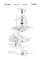
- FIG. 2is an exploded perspective view of the patelar clamp and saw guide of FIG. 1.
- FIG. 3is an enlarged, exploded perspective view of a conector for use with the clamp of FIG. 1.
- FIG. 4is a through section of portions of the connector of FIG. 3 taken along line 4--4.
- FIG. 5is a perspective view of a storage apparatus for additional caps for use in the clamp of FIG. 1.
- FIG. 6is a through section of the storage apparatus of FIG. 5 taken along line 6--6.
- FIG. 1is a perspective view of a patellar clamp and saw guide 10 according to our present invention.
- the clamp 10comprises a bracket 12 which supports a base 14.
- a surgeonwould lay a patient's patella on a upper surface 16 of the base 14.
- the upper surface 16is slightly concave to conform generally to the expected convex shape of the patella.
- Pins 17may protrude from the upper surface 16 to resist movement of the patella.
- the bracket 12is curved into a C-shape.
- a "T" handle 24is provided on a proximal end 26 of the bolt 20 so that adequate torque can be imparted to the bolt.
- the connector 30is comprised of an inner sleeve 32 and an outer sleeve 34, as shown in FIGS. 2 and 3.
- the inner sleeve 32has an upper threaded bore 36 for attachment to the bolt 20.
- Wrench flats 38, 40are provided on a upper lip 42 for tightening the inner sleeve 32 to the bolt 20.
- Three axial bores, 42, 44, 46are provided to receive balls 48, 50, 52 respectively.
- a lip 54is provided to prevent the balls 48, 50, 52 from falling into the interior of the sleeve 32.
- a groove 56is provided at a bottom end 58 of the inner sleeve 32 for receiving a split ring 60.
- the outer ring 34has an upper bore 62 which terminates in a lip 64.
- the fitment 70comprises a cylindrical stem 74 with a circumferential groove 76 for engaging the balls 48, 50, 52.
- the cap 72is generally circular and, like the base, has a concave surface 78 which is tightened against the patella.
- one or more pinsmay be provided on the concave surface 78 to more securely grip the patella and prevent any motion of the patella relative to the clamp.
- An adjustable scale 80is also attached to the cap 72.
- Two arms 82, 84extend radially outward from an edge 86 of the cap 72. Between the two arms 82, 84 is placed a sliding scale 88 which has adjustment tab 90 on one end and a feeler 92 on the other.
- the sliding scale 88is retained between the arms 82, 84 with a end cap 94 which may be attached to the arms 82, 84 by screws (not shown) or other fasteners.
- a scale lock 96is provided to hold the scale 80 in a selected position.
- the scale lock 96comprises a bolt 98 with a lever 100 for tightening.
- the scale lock 96can be screwed through a threaded bore in one of the arms 82 to press the scale 88 against the other arm 84 and thereby secure the scale.
- the use of the scale 88will be more fully explained below.
- the bracket 12Underneath the bracket 12 is a T-shaped guide plate 102.
- a central stem 104 of the guide plate 102has a bore 106.
- a bolt 108 on a handle 110passes through the bore 106 and into a threaded bore 112 in the bracket 12.
- the guide plate 102By turning the handle 110, the guide plate 102 can be tightened against the bracket 12 and held in a selected position. If the handle is loosened, the guide plate can swing around the base 14. This permits a surgeon to select a appropriate angle for sawing a patella and also permits the surgeon to use the clamp and saw guide on either right or left knee of a patient.
- Two arms 114, 116extend on either side of the central stem 104. Each arm 114, 116 supports a guide pin 118, 120, respectively.
- a saw block 122is mounted on the guide plate 102. The guide pins 118, 120 slide in guide holes 124, 126, respectively, in the saw block 122.
- a slot 128 in the saw block 122receives a sagittal blade and holds the saw blade in a plane perpendicular to an axis through the bolt 20 and the handle 110.
- a lower edge 130 of the slot 128is extended so that the feeler 92 on the scale 88 can rest against it. This permits a measurement to be made from an upper side 132 of the cap 72 to the lower edge 130 of the slots 128.
- Markings on the scale 88are calibrated so that the measurement read on the scale gives the distance from the top of a patella held against the concave surface 78 of the cap to the bottom edge of the intended cut.
- the desired depth of cutwould be set on the scale and the scale locked in position with the scale lock. Then saw block would be advanced against the scale. Before a cut would be made, the scale would be moved.
- the saw block 122is advanced using a jack screw 134 which passes through a threaded bore 136 in the guide plate 102.
- the jack screwcomprises a knob 138 and a bolt 140.
- a collar 142is also attached to the bolt 140.
- the collar 142comprises a upper disk 144 and a lower disk 146 separated by a spacer 148.
- the upper disk 144 and the spacer 148engage a T-shaped slot 150 in the saw block.
- the lower disk 146presses against an under side 152 of the saw block.
- a relief bore 154 in the guide platepermits the saw block 122 to be set flush against guide plate.
- the scale 88can be moved and the blade of the sagittal saw can be passed through slot 128. The surgeon can then remove a precisely determined amount of the patella and produce a surface which is both flat and in an appropriate plane with respect to the remaining patella for receiving a patellar prosthesis.
- the storage apparatuscomprises an elastomeric cored plug 158 adapted to be inserted in a bore in the bottom end of the handle 110.
- the cored plug 158has a central core 160 for receiving a fitment 70.
- a circumferential groove 162is provided for receiving a elastic o-ring 164.
- Three equally spaced radial through bores 166, 168, 170are provided for receiving balls 172, 174 and 176 respectively.
- an inner lip 178is provided on each of the bores 166, 168, 170 to prevent the balls from being forced into the core 160. Because of the elastic nature of the o-ring 164, a fitment 70 on the cap 72 can be snapped in the storage apparatus for temporary storage.
Landscapes
- Health & Medical Sciences (AREA)
- Surgery (AREA)
- Life Sciences & Earth Sciences (AREA)
- Biomedical Technology (AREA)
- Medical Informatics (AREA)
- Oral & Maxillofacial Surgery (AREA)
- Nuclear Medicine, Radiotherapy & Molecular Imaging (AREA)
- Transplantation (AREA)
- Physical Education & Sports Medicine (AREA)
- Engineering & Computer Science (AREA)
- Orthopedic Medicine & Surgery (AREA)
- Heart & Thoracic Surgery (AREA)
- Dentistry (AREA)
- Molecular Biology (AREA)
- Animal Behavior & Ethology (AREA)
- General Health & Medical Sciences (AREA)
- Public Health (AREA)
- Veterinary Medicine (AREA)
- Prostheses (AREA)
- Surgical Instruments (AREA)
Abstract
Description
Claims (12)
Priority Applications (1)
| Application Number | Priority Date | Filing Date | Title |
|---|---|---|---|
| US07/585,315US5021055A (en) | 1990-09-19 | 1990-09-19 | Patellar clamp and surgical saw guide |
Applications Claiming Priority (1)
| Application Number | Priority Date | Filing Date | Title |
|---|---|---|---|
| US07/585,315US5021055A (en) | 1990-09-19 | 1990-09-19 | Patellar clamp and surgical saw guide |
Publications (1)
| Publication Number | Publication Date |
|---|---|
| US5021055Atrue US5021055A (en) | 1991-06-04 |
Family
ID=24340918
Family Applications (1)
| Application Number | Title | Priority Date | Filing Date |
|---|---|---|---|
| US07/585,315Expired - LifetimeUS5021055A (en) | 1990-09-19 | 1990-09-19 | Patellar clamp and surgical saw guide |
Country Status (1)
| Country | Link |
|---|---|
| US (1) | US5021055A (en) |
Cited By (53)
| Publication number | Priority date | Publication date | Assignee | Title |
|---|---|---|---|---|
| US5129907A (en)* | 1990-12-10 | 1992-07-14 | Zimmer, Inc. | Patellar clamp and reamer with adjustable stop |
| US5147365A (en)* | 1991-08-19 | 1992-09-15 | Intermedics Orthopedics, Inc. | Patellar osteotomy guide |
| US5207680A (en)* | 1992-05-11 | 1993-05-04 | Zimmer, Inc. | Front milling guide for use in orthopaedic surgery |
| US5417693A (en)* | 1992-06-17 | 1995-05-23 | Minnesota Mining And Manufacturing Company | Instrumentation for preparing the femur for an artificial knee implant and for positioning the femoral component of the implant |
| US5437676A (en)* | 1994-01-27 | 1995-08-01 | Developpement D'implants Orthopediques Et Medicaux | Kneecap cutting device for the fitting of a total knee replacement |
| US5437677A (en)* | 1992-10-09 | 1995-08-01 | Minnesota Mining And Manufacturing Company | Glenoid alignment guide |
| WO1996025115A1 (en) | 1995-02-15 | 1996-08-22 | Smith & Nephew Richards Inc. | Patella clamp apparatus |
| US5616146A (en)* | 1994-05-16 | 1997-04-01 | Murray; William M. | Method and apparatus for machining bone to fit an orthopedic surgical implant |
| US5941884A (en)* | 1998-10-09 | 1999-08-24 | Osteonics Corp. | Patella preparation apparatus and method |
| US6174314B1 (en) | 1998-12-15 | 2001-01-16 | David D. Waddell | In situ pattellar resection guide |
| US20030009170A1 (en)* | 2001-07-09 | 2003-01-09 | Alain Tornier | Ancillary tool for fitting an ulnar component and/or a radial component of an elbow prosthesis |
| US20040087961A1 (en)* | 2002-09-03 | 2004-05-06 | Wood Steven R. | Patellar milling clamp |
| US20040162561A1 (en)* | 2003-02-13 | 2004-08-19 | Howmedica Osteonics Corp. | Modular patella instrument |
| US20060058803A1 (en)* | 2003-10-08 | 2006-03-16 | Biomet Manufacturing Corp. | Bone cutting apparatus |
| US20060155292A1 (en)* | 2002-09-19 | 2006-07-13 | Jeganath Krishnan | Implant clamp and method |
| US20060241633A1 (en)* | 2005-04-26 | 2006-10-26 | Greg Stalcup | Patella protector |
| US20070233142A1 (en)* | 2006-03-14 | 2007-10-04 | Oliver Ralph S | Apparatus and method for implementing patella resection guide during minimally invasive surgery |
| US20080097450A1 (en)* | 2006-09-14 | 2008-04-24 | Zimmer Technology, Inc. | Patella clamp |
| US20080177394A1 (en)* | 2006-10-18 | 2008-07-24 | Howmedica Osteonics Corp. | Mis patellar preparation |
| US20080228190A1 (en)* | 2007-03-02 | 2008-09-18 | Eugene Sherry | In situ patellar fixing system |
| US7632279B2 (en) | 2004-12-27 | 2009-12-15 | Howmedica Osteonics Corp. | Patella resection clamp |
| ITPO20080015A1 (en)* | 2008-10-21 | 2010-04-22 | Andrea Baldini | TOOL TO START THE ROTULA RESECTION IN A GUIDED MANNER DURING THE KNEE TOTAL PROSTHESIS INTERVENTION |
| US20120101505A1 (en)* | 2010-10-26 | 2012-04-26 | Zimmer, Inc. | Patellar resection instrument with variable depth guide |
| WO2012176054A1 (en)* | 2011-06-22 | 2012-12-27 | Medacta International S.A. | Device for patellar resurfacing |
| US20130030539A1 (en)* | 2011-06-30 | 2013-01-31 | Wright Abraham P | Patella orthopaedic surgical method |
| EP2574290A1 (en)* | 2011-09-28 | 2013-04-03 | DePuy Products, Inc. | Patella resection assembly |
| WO2013116930A1 (en)* | 2012-02-06 | 2013-08-15 | Uti Limited Partnership | Marking device and evaluating device for patellar resection |
| US8821501B2 (en) | 2010-09-24 | 2014-09-02 | Depuy (Ireland) | Patella resectioning guide and assembly |
| US8945135B2 (en) | 2011-02-14 | 2015-02-03 | Michael D. Ries | Patellar prostheses and instrumentation |
| US8951262B2 (en) | 2011-06-30 | 2015-02-10 | Depuy (Ireland) | Patella clamp and drill guide surgical instrument |
| US8968321B2 (en) | 2011-06-30 | 2015-03-03 | Depuy (Ireland) | Patella resection guide with locating features and method of using the same |
| US8979854B2 (en) | 2011-06-30 | 2015-03-17 | Depuy (Ireland) | Patella orthopaedic surgical instrument assembly |
| US8998912B2 (en) | 2011-09-28 | 2015-04-07 | Depuy (Ireland) | Clamping patella drill guide |
| US8998913B2 (en) | 2011-09-28 | 2015-04-07 | Depuy (Ireland) | Patella resection assembly |
| US9078676B2 (en) | 2011-09-28 | 2015-07-14 | Depuy (Ireland) | Patella drilling system |
| US9078772B2 (en) | 2011-09-28 | 2015-07-14 | Depuy (Ireland) | Rotatable patella drill guide |
| US9192459B2 (en) | 2000-01-14 | 2015-11-24 | Bonutti Skeletal Innovations Llc | Method of performing total knee arthroplasty |
| US9554813B2 (en) | 2012-09-28 | 2017-01-31 | Depuy Ireland Unlimited Company | Patella drill guide and trial surgical instrument |
| US9603721B2 (en)* | 2014-08-01 | 2017-03-28 | Boyer Anderson, LLC | Contact surface adapter and components for artificial prosthesis installation clamp |
| US9675399B2 (en) | 2011-02-14 | 2017-06-13 | Michael D. Ries | Patient specific implants and instrumentation for patellar prostheses |
| US10085758B2 (en) | 2012-09-28 | 2018-10-02 | Depuy Ireland Unlimited Company | Patella drill guide and trial surgical instrument having an alignment bore formed therein and method of using the same |
| KR20190011859A (en)* | 2017-07-25 | 2019-02-08 | 주식회사 코렌텍 | Patient-Specific Artificial Shoulder Joint Surgical Instruments |
| CN109700502A (en)* | 2019-02-25 | 2019-05-03 | 上海节惠生物科技有限公司 | A kind of clipping kneecap holdfast guider |
| US10278714B2 (en) | 2015-03-27 | 2019-05-07 | Depuy Ireland Unlimted Company | Orthopaedic surgical instrument system for implanting a prosthetic patella component and method of use |
| US10335163B2 (en) | 2013-03-05 | 2019-07-02 | Depuy Ireland Unlimited Company | Polymer 4-in-2 femoral cutting instrument having separable A/P and chamfer cutting blocks |
| US10426565B2 (en) | 2015-03-25 | 2019-10-01 | E. Marlowe Goble | Knee instruments and methods |
| US10568650B2 (en) | 2015-03-25 | 2020-02-25 | E. Marlowe Goble | Knee instruments and methods |
| US20210386436A1 (en)* | 2018-10-05 | 2021-12-16 | Smith & Nephew, Inc. | Tendon harvesting system |
| US11234720B2 (en) | 2018-03-07 | 2022-02-01 | E. Marlowe Goble | Knee instruments and methods |
| EP3981341A1 (en)* | 2020-10-06 | 2022-04-13 | Aesculap AG | Patella preparation system |
| WO2023107443A1 (en)* | 2021-12-09 | 2023-06-15 | Smith & Nephew, Inc. | Patella clamp and patella tracking system |
| US20230329728A1 (en)* | 2020-10-16 | 2023-10-19 | Howmedica Osteonics Corp. | Patella Resection Guide with Independent Adjustment |
| US12076025B2 (en) | 2022-05-11 | 2024-09-03 | DePuy Synthes Products, Inc. | Polymer cutting block |
Citations (7)
| Publication number | Priority date | Publication date | Assignee | Title |
|---|---|---|---|---|
| US4633862A (en)* | 1985-05-30 | 1987-01-06 | Petersen Thomas D | Patellar resection sawguide |
| US4703751A (en)* | 1986-03-27 | 1987-11-03 | Pohl Kenneth P | Method and apparatus for resecting a distal femoral surface |
| US4759350A (en)* | 1986-10-17 | 1988-07-26 | Dunn Harold K | Instruments for shaping distal femoral and proximal tibial surfaces |
| US4892093A (en)* | 1988-10-28 | 1990-01-09 | Osteonics Corp. | Femoral cutting guide |
| US4893619A (en)* | 1988-02-04 | 1990-01-16 | Intermedics Orthopedics, Inc. | Humeral osteotomy guide |
| US4952213A (en)* | 1989-02-03 | 1990-08-28 | Boehringer Mannheim Corporation | Tibial cutting guide |
| US4952214A (en)* | 1981-08-20 | 1990-08-28 | Ohio Medical Instrument Co., Inc. | Arcuate osteotomy blade, blade guide, and cutting method |
- 1990
- 1990-09-19USUS07/585,315patent/US5021055A/ennot_activeExpired - Lifetime
Patent Citations (7)
| Publication number | Priority date | Publication date | Assignee | Title |
|---|---|---|---|---|
| US4952214A (en)* | 1981-08-20 | 1990-08-28 | Ohio Medical Instrument Co., Inc. | Arcuate osteotomy blade, blade guide, and cutting method |
| US4633862A (en)* | 1985-05-30 | 1987-01-06 | Petersen Thomas D | Patellar resection sawguide |
| US4703751A (en)* | 1986-03-27 | 1987-11-03 | Pohl Kenneth P | Method and apparatus for resecting a distal femoral surface |
| US4759350A (en)* | 1986-10-17 | 1988-07-26 | Dunn Harold K | Instruments for shaping distal femoral and proximal tibial surfaces |
| US4893619A (en)* | 1988-02-04 | 1990-01-16 | Intermedics Orthopedics, Inc. | Humeral osteotomy guide |
| US4892093A (en)* | 1988-10-28 | 1990-01-09 | Osteonics Corp. | Femoral cutting guide |
| US4952213A (en)* | 1989-02-03 | 1990-08-28 | Boehringer Mannheim Corporation | Tibial cutting guide |
Cited By (90)
| Publication number | Priority date | Publication date | Assignee | Title |
|---|---|---|---|---|
| US5129907A (en)* | 1990-12-10 | 1992-07-14 | Zimmer, Inc. | Patellar clamp and reamer with adjustable stop |
| US5147365A (en)* | 1991-08-19 | 1992-09-15 | Intermedics Orthopedics, Inc. | Patellar osteotomy guide |
| US5207680A (en)* | 1992-05-11 | 1993-05-04 | Zimmer, Inc. | Front milling guide for use in orthopaedic surgery |
| US5417693A (en)* | 1992-06-17 | 1995-05-23 | Minnesota Mining And Manufacturing Company | Instrumentation for preparing the femur for an artificial knee implant and for positioning the femoral component of the implant |
| US5437677A (en)* | 1992-10-09 | 1995-08-01 | Minnesota Mining And Manufacturing Company | Glenoid alignment guide |
| US5437676A (en)* | 1994-01-27 | 1995-08-01 | Developpement D'implants Orthopediques Et Medicaux | Kneecap cutting device for the fitting of a total knee replacement |
| US5616146A (en)* | 1994-05-16 | 1997-04-01 | Murray; William M. | Method and apparatus for machining bone to fit an orthopedic surgical implant |
| WO1996025115A1 (en) | 1995-02-15 | 1996-08-22 | Smith & Nephew Richards Inc. | Patella clamp apparatus |
| US5575793A (en)* | 1995-02-15 | 1996-11-19 | Smith & Nephew Richards Inc. | Patella clamp apparatus |
| US5941884A (en)* | 1998-10-09 | 1999-08-24 | Osteonics Corp. | Patella preparation apparatus and method |
| US6174314B1 (en) | 1998-12-15 | 2001-01-16 | David D. Waddell | In situ pattellar resection guide |
| US6228090B1 (en) | 1998-12-15 | 2001-05-08 | David D. Waddell | Osteotomy trial mounting device and method |
| US9192459B2 (en) | 2000-01-14 | 2015-11-24 | Bonutti Skeletal Innovations Llc | Method of performing total knee arthroplasty |
| US7922728B2 (en)* | 2001-07-09 | 2011-04-12 | Tornier Sas | Ancillary tool for fitting an ulnar component and/or a radial component of an elbow prosthesis |
| US20030009170A1 (en)* | 2001-07-09 | 2003-01-09 | Alain Tornier | Ancillary tool for fitting an ulnar component and/or a radial component of an elbow prosthesis |
| US6866667B2 (en) | 2002-09-03 | 2005-03-15 | Symmetry Medical, Inc. | Patellar milling clamp |
| US20040087961A1 (en)* | 2002-09-03 | 2004-05-06 | Wood Steven R. | Patellar milling clamp |
| US20060155292A1 (en)* | 2002-09-19 | 2006-07-13 | Jeganath Krishnan | Implant clamp and method |
| US20070118141A1 (en)* | 2003-02-13 | 2007-05-24 | Howmedica Osteonics Corp. | Modular patella instrument |
| US20040162561A1 (en)* | 2003-02-13 | 2004-08-19 | Howmedica Osteonics Corp. | Modular patella instrument |
| US8216242B2 (en) | 2003-02-13 | 2012-07-10 | Howmedica Osteonics Corp. | Modular patella instrument |
| US20060058803A1 (en)* | 2003-10-08 | 2006-03-16 | Biomet Manufacturing Corp. | Bone cutting apparatus |
| US7674268B2 (en)* | 2003-10-08 | 2010-03-09 | Biomet Manufacturing Corp. | Bone cutting apparatus |
| US7632279B2 (en) | 2004-12-27 | 2009-12-15 | Howmedica Osteonics Corp. | Patella resection clamp |
| US20060241633A1 (en)* | 2005-04-26 | 2006-10-26 | Greg Stalcup | Patella protector |
| US20070233142A1 (en)* | 2006-03-14 | 2007-10-04 | Oliver Ralph S | Apparatus and method for implementing patella resection guide during minimally invasive surgery |
| US8182488B2 (en) | 2006-03-14 | 2012-05-22 | Ralph Scott Oliver | Apparatus and method for implementing patella resection guide during minimally invasive surgery |
| US20080097450A1 (en)* | 2006-09-14 | 2008-04-24 | Zimmer Technology, Inc. | Patella clamp |
| US20100160915A1 (en)* | 2006-10-18 | 2010-06-24 | Howmedica Osteonics Corp. | Mis patellar preparation |
| US7758651B2 (en) | 2006-10-18 | 2010-07-20 | Howmedica Osteonics Corp. | Mis patellar preparation |
| US20080177394A1 (en)* | 2006-10-18 | 2008-07-24 | Howmedica Osteonics Corp. | Mis patellar preparation |
| US20080228190A1 (en)* | 2007-03-02 | 2008-09-18 | Eugene Sherry | In situ patellar fixing system |
| US8147497B2 (en)* | 2007-03-02 | 2012-04-03 | Greatbatch Medical S.A. | In situ patellar fixing system |
| EP2198789A1 (en)* | 2008-10-21 | 2010-06-23 | WALDEMAR LINK GmbH & Co. KG | Patellar saw cutting guide |
| ITPO20080015A1 (en)* | 2008-10-21 | 2010-04-22 | Andrea Baldini | TOOL TO START THE ROTULA RESECTION IN A GUIDED MANNER DURING THE KNEE TOTAL PROSTHESIS INTERVENTION |
| US8821501B2 (en) | 2010-09-24 | 2014-09-02 | Depuy (Ireland) | Patella resectioning guide and assembly |
| US20120101505A1 (en)* | 2010-10-26 | 2012-04-26 | Zimmer, Inc. | Patellar resection instrument with variable depth guide |
| US8747410B2 (en)* | 2010-10-26 | 2014-06-10 | Zimmer, Inc. | Patellar resection instrument with variable depth guide |
| US9675399B2 (en) | 2011-02-14 | 2017-06-13 | Michael D. Ries | Patient specific implants and instrumentation for patellar prostheses |
| US8945135B2 (en) | 2011-02-14 | 2015-02-03 | Michael D. Ries | Patellar prostheses and instrumentation |
| US9743941B2 (en) | 2011-06-22 | 2017-08-29 | Medacta International Sa | Device for patellar resurfacing |
| WO2012176054A1 (en)* | 2011-06-22 | 2012-12-27 | Medacta International S.A. | Device for patellar resurfacing |
| US8951262B2 (en) | 2011-06-30 | 2015-02-10 | Depuy (Ireland) | Patella clamp and drill guide surgical instrument |
| US9414851B2 (en) | 2011-06-30 | 2016-08-16 | Depuy (Ireland) | Patella clamp and drill guide surgical instrument and method of use |
| US20130030539A1 (en)* | 2011-06-30 | 2013-01-31 | Wright Abraham P | Patella orthopaedic surgical method |
| US8968321B2 (en) | 2011-06-30 | 2015-03-03 | Depuy (Ireland) | Patella resection guide with locating features and method of using the same |
| US8979854B2 (en) | 2011-06-30 | 2015-03-17 | Depuy (Ireland) | Patella orthopaedic surgical instrument assembly |
| US8986306B2 (en)* | 2011-06-30 | 2015-03-24 | Depuy (Ireland) | Patella orthopaedic surgical method |
| EP2574290A1 (en)* | 2011-09-28 | 2013-04-03 | DePuy Products, Inc. | Patella resection assembly |
| US8998913B2 (en) | 2011-09-28 | 2015-04-07 | Depuy (Ireland) | Patella resection assembly |
| US9078676B2 (en) | 2011-09-28 | 2015-07-14 | Depuy (Ireland) | Patella drilling system |
| US9078772B2 (en) | 2011-09-28 | 2015-07-14 | Depuy (Ireland) | Rotatable patella drill guide |
| JP2013071009A (en)* | 2011-09-28 | 2013-04-22 | Depuy Products Inc | Patella resection assembly |
| US9295483B2 (en) | 2011-09-28 | 2016-03-29 | Depuy (Ireland) | Rotatable patella drill guide |
| US8998912B2 (en) | 2011-09-28 | 2015-04-07 | Depuy (Ireland) | Clamping patella drill guide |
| US8915923B2 (en) | 2011-09-28 | 2014-12-23 | Depuy (Ireland) | Patella resection assembly |
| WO2013116930A1 (en)* | 2012-02-06 | 2013-08-15 | Uti Limited Partnership | Marking device and evaluating device for patellar resection |
| US11925365B2 (en) | 2012-09-28 | 2024-03-12 | Depuy Ireland Unlimited Company | Patella drill guide and trial surgical instrument |
| US11109873B2 (en) | 2012-09-28 | 2021-09-07 | Depuy Ireland Unlimited Company | Patella drill guide and trial surgical instrument system and method of using the same |
| US9855065B2 (en) | 2012-09-28 | 2018-01-02 | Depuy Ireland Unlimited Company | Orthopaedic surgical instrument assembly for implanting a prosthetic patella component |
| US10085758B2 (en) | 2012-09-28 | 2018-10-02 | Depuy Ireland Unlimited Company | Patella drill guide and trial surgical instrument having an alignment bore formed therein and method of using the same |
| US9700330B2 (en) | 2012-09-28 | 2017-07-11 | Depuy Ireland Unlimited Company | Method for surgically implanting a prosthetic patella component |
| US9554813B2 (en) | 2012-09-28 | 2017-01-31 | Depuy Ireland Unlimited Company | Patella drill guide and trial surgical instrument |
| US11234711B2 (en) | 2013-03-05 | 2022-02-01 | Depuy Ireland Unlimited Company | Polymer 4-in-2 femoral cutting instrument having separable A/P and chamfer cutting blocks |
| US10335163B2 (en) | 2013-03-05 | 2019-07-02 | Depuy Ireland Unlimited Company | Polymer 4-in-2 femoral cutting instrument having separable A/P and chamfer cutting blocks |
| US9603721B2 (en)* | 2014-08-01 | 2017-03-28 | Boyer Anderson, LLC | Contact surface adapter and components for artificial prosthesis installation clamp |
| US10034775B2 (en) | 2014-08-01 | 2018-07-31 | Boyer Anderson, LLC | Contact surface adapter and components for artificial prosthesis installation clamp |
| US10426565B2 (en) | 2015-03-25 | 2019-10-01 | E. Marlowe Goble | Knee instruments and methods |
| US10568650B2 (en) | 2015-03-25 | 2020-02-25 | E. Marlowe Goble | Knee instruments and methods |
| US11337711B2 (en) | 2015-03-25 | 2022-05-24 | E. Marlowe Goble | Knee instruments and methods |
| US11266423B2 (en) | 2015-03-25 | 2022-03-08 | E. Marlowe Goble | Knee instruments and methods |
| US11246609B2 (en) | 2015-03-25 | 2022-02-15 | E. Marlowe Goble | Knee instruments and methods |
| US10278714B2 (en) | 2015-03-27 | 2019-05-07 | Depuy Ireland Unlimted Company | Orthopaedic surgical instrument system for implanting a prosthetic patella component and method of use |
| US12167862B2 (en) | 2015-03-27 | 2024-12-17 | Depuy Ireland Unlimited Company | Orthopaedic surgical instrument system for implanting a prosthetic patella component and method of use |
| US11304711B2 (en) | 2015-03-27 | 2022-04-19 | Depuy Ireland Unlimited Company | Orthopaedic surgical instrument system for implanting a prosthetic patella component and method of use |
| US12156663B2 (en) | 2015-03-27 | 2024-12-03 | Depuy Ireland Unlimited Company | Orthopaedic surgical instrument system for implanting a prosthetic patella component and method of use |
| KR20190011859A (en)* | 2017-07-25 | 2019-02-08 | 주식회사 코렌텍 | Patient-Specific Artificial Shoulder Joint Surgical Instruments |
| US11234720B2 (en) | 2018-03-07 | 2022-02-01 | E. Marlowe Goble | Knee instruments and methods |
| US20210386436A1 (en)* | 2018-10-05 | 2021-12-16 | Smith & Nephew, Inc. | Tendon harvesting system |
| US12167861B2 (en)* | 2018-10-05 | 2024-12-17 | Smith & Nephew, Inc. | Tendon harvesting system |
| CN109700502B (en)* | 2019-02-25 | 2023-12-29 | 上海节惠生物科技有限公司 | Clamping type patella anchor guide |
| CN109700502A (en)* | 2019-02-25 | 2019-05-03 | 上海节惠生物科技有限公司 | A kind of clipping kneecap holdfast guider |
| JP2023544786A (en)* | 2020-10-06 | 2023-10-25 | アエスキュラップ アーゲー | patella preparation system |
| US20230404598A1 (en)* | 2020-10-06 | 2023-12-21 | Aesculap Ag | Patella preparation system |
| WO2022073871A1 (en)* | 2020-10-06 | 2022-04-14 | Aesculap Ag | Patella preparation system |
| EP3981341A1 (en)* | 2020-10-06 | 2022-04-13 | Aesculap AG | Patella preparation system |
| US20230329728A1 (en)* | 2020-10-16 | 2023-10-19 | Howmedica Osteonics Corp. | Patella Resection Guide with Independent Adjustment |
| US12274457B2 (en)* | 2020-10-16 | 2025-04-15 | Howmedica Osteonics Corp. | Patella resection guide with independent adjustment |
| WO2023107443A1 (en)* | 2021-12-09 | 2023-06-15 | Smith & Nephew, Inc. | Patella clamp and patella tracking system |
| US12076025B2 (en) | 2022-05-11 | 2024-09-03 | DePuy Synthes Products, Inc. | Polymer cutting block |
Similar Documents
| Publication | Publication Date | Title |
|---|---|---|
| US5021055A (en) | Patellar clamp and surgical saw guide | |
| US5542947A (en) | Slotted patella resection guide and stylus | |
| US5733290A (en) | Quick-release tibial alignment handle | |
| US5669914A (en) | Rotation alignment instrument | |
| AU595265B2 (en) | Femoral surface shaping apparatus for posterior- stabilized knee implants | |
| EP1082943B1 (en) | Prothesis positioning apparatus | |
| US9066804B2 (en) | Method and apparatus for femoral and tibial resection | |
| US5486177A (en) | Patella planer with adjustable stop | |
| US5536271A (en) | Patella reaming system | |
| AU777429B2 (en) | Knee prosthesis system | |
| US5628749A (en) | Tibial resection instrumentation and surgical method | |
| US5417693A (en) | Instrumentation for preparing the femur for an artificial knee implant and for positioning the femoral component of the implant | |
| AU605016B2 (en) | Prosthetic knee joint with improved patellar component tracking | |
| US8603095B2 (en) | Apparatuses for femoral and tibial resection | |
| AU2014201204B2 (en) | Tibial trial instruments for setting offset | |
| US9216089B2 (en) | Method of surgically preparing a patient's tibia | |
| EP2540239A1 (en) | Patella drill guide and clamp assembly | |
| EP2540234A1 (en) | Patella resection guide with locating features | |
| EP2540233A1 (en) | Patella orthopaedic surgical instrument assembly | |
| CA3024505A1 (en) | System and method for preparing a patient's tibia in an orthopaedic joint replacement procedure | |
| AU2014201412B2 (en) | Surgical instrument and method of use | |
| US12251324B2 (en) | Removable inclination guide for an implant insertion tool and associated surgical method | |
| US7048742B2 (en) | Insertion instrument for sliding prostheses | |
| US20190388241A1 (en) | Orthopaedic surgical instrument for an acetabular prosthetic component | |
| US11648018B2 (en) | Orthopaedic surgical instrument |
Legal Events
| Date | Code | Title | Description |
|---|---|---|---|
| AS | Assignment | Owner name:INTERMEDICS ORTHOPEDICS, INC., A TX CORP., TEXAS Free format text:ASSIGNMENT OF ASSIGNORS INTEREST.;ASSIGNORS:BURKINSHAW, BRIAN D.;BROWN, STEVEN G.;REEL/FRAME:005451/0942 Effective date:19900914 | |
| STCF | Information on status: patent grant | Free format text:PATENTED CASE | |
| FEPP | Fee payment procedure | Free format text:PAYOR NUMBER ASSIGNED (ORIGINAL EVENT CODE: ASPN); ENTITY STATUS OF PATENT OWNER: LARGE ENTITY | |
| FPAY | Fee payment | Year of fee payment:4 | |
| FPAY | Fee payment | Year of fee payment:8 | |
| FPAY | Fee payment | Year of fee payment:12 | |
| AS | Assignment | Owner name:CENTERPULSE ORTHOPEDICS INC., TEXAS Free format text:CHANGE OF NAME;ASSIGNOR:SULZER ORTHOPEDICS INC.;REEL/FRAME:013516/0549 Effective date:20020930 | |
| AS | Assignment | Owner name:SULZER ORTHOPEDICS, INC., ILLINOIS Free format text:CHANGE OF NAME;ASSIGNOR:INTERMEDICS ORTHOPEDICS, INC.;REEL/FRAME:015177/0137 Effective date:19970106 | |
| AS | Assignment | Owner name:ZIMMER AUSTIN, INC., TEXAS Free format text:CHANGE OF NAME;ASSIGNOR:CENTERPULSE ORTHOPEDICS INC.;REEL/FRAME:016263/0264 Effective date:20040602 | |
| AS | Assignment | Owner name:CENTERPULSE ORTHOPEDICS INC., TEXAS Free format text:CHANGE OF NAME;ASSIGNOR:SULZER ORTHOPEDICS INC.;REEL/FRAME:016761/0136 Effective date:20020930 | |
| AS | Assignment | Owner name:ZIMMER, INC., INDIANA Free format text:CHANGE OF NAME;ASSIGNOR:ZIMMER AUSTIN, INC.;REEL/FRAME:017435/0714 Effective date:20060208 |