US5020745A - Reaction wheel fricton compensation using dither - Google Patents
Reaction wheel fricton compensation using ditherDownload PDFInfo
- Publication number
- US5020745A US5020745AUS07/454,651US45465189AUS5020745AUS 5020745 AUS5020745 AUS 5020745AUS 45465189 AUS45465189 AUS 45465189AUS 5020745 AUS5020745 AUS 5020745A
- Authority
- US
- United States
- Prior art keywords
- signal
- wheel
- spacecraft
- attitude
- torque command
- Prior art date
- Legal status (The legal status is an assumption and is not a legal conclusion. Google has not performed a legal analysis and makes no representation as to the accuracy of the status listed.)
- Expired - Lifetime
Links
- 238000006243chemical reactionMethods0.000titleclaimsdescription38
- 238000000034methodMethods0.000claimsdescription3
- 230000002441reversible effectEffects0.000claimsdescription3
- 230000001133accelerationEffects0.000claims1
- 230000008878couplingEffects0.000claims1
- 238000010168coupling processMethods0.000claims1
- 238000005859coupling reactionMethods0.000claims1
- 230000003068static effectEffects0.000description6
- 238000010586diagramMethods0.000description4
- 238000004364calculation methodMethods0.000description2
- 238000004891communicationMethods0.000description2
- 238000005094computer simulationMethods0.000description1
- 230000003247decreasing effectEffects0.000description1
- 230000000694effectsEffects0.000description1
- 230000007613environmental effectEffects0.000description1
- 238000010304firingMethods0.000description1
- 239000012530fluidSubstances0.000description1
- 239000000446fuelSubstances0.000description1
- 230000010354integrationEffects0.000description1
- 230000003993interactionEffects0.000description1
- 238000013139quantizationMethods0.000description1
- 238000011084recoveryMethods0.000description1
- 238000009987spinningMethods0.000description1
- 230000006641stabilisationEffects0.000description1
- 238000011105stabilizationMethods0.000description1
- 230000002459sustained effectEffects0.000description1
Images


Classifications
- B—PERFORMING OPERATIONS; TRANSPORTING
- B64—AIRCRAFT; AVIATION; COSMONAUTICS
- B64G—COSMONAUTICS; VEHICLES OR EQUIPMENT THEREFOR
- B64G1/00—Cosmonautic vehicles
- B64G1/22—Parts of, or equipment specially adapted for fitting in or to, cosmonautic vehicles
- B64G1/24—Guiding or controlling apparatus, e.g. for attitude control
- B64G1/36—Guiding or controlling apparatus, e.g. for attitude control using sensors, e.g. sun-sensors, horizon sensors
- B—PERFORMING OPERATIONS; TRANSPORTING
- B64—AIRCRAFT; AVIATION; COSMONAUTICS
- B64G—COSMONAUTICS; VEHICLES OR EQUIPMENT THEREFOR
- B64G1/00—Cosmonautic vehicles
- B64G1/22—Parts of, or equipment specially adapted for fitting in or to, cosmonautic vehicles
- B64G1/24—Guiding or controlling apparatus, e.g. for attitude control
- B64G1/244—Spacecraft control systems
- B—PERFORMING OPERATIONS; TRANSPORTING
- B64—AIRCRAFT; AVIATION; COSMONAUTICS
- B64G—COSMONAUTICS; VEHICLES OR EQUIPMENT THEREFOR
- B64G1/00—Cosmonautic vehicles
- B64G1/22—Parts of, or equipment specially adapted for fitting in or to, cosmonautic vehicles
- B64G1/24—Guiding or controlling apparatus, e.g. for attitude control
- B64G1/28—Guiding or controlling apparatus, e.g. for attitude control using inertia or gyro effect
- B64G1/283—Guiding or controlling apparatus, e.g. for attitude control using inertia or gyro effect using reaction wheels
Definitions
- This inventionrelates to attitude control systems for spacecraft using reaction wheels, and more particularly to reduction in attitude errors during times when the wheel speed is reduced to zero and the direction of rotation is reversed.
- Spacecrafthave become important as platforms for communications or sensors.
- the position or attitude of the spacecraft in spacemust be maintained constant relative to a distant object, such as the heavenly body which it orbits.
- the sensors or communication devicescannot be pointed in the desired direction with the desired accuracy.
- Certain types of spacecraftare stabilized by spinning about an axis. With such spacecraft, the attitude of the spacecraft in inertial space remains essentially constant. While this may be desirable when a sensor is to be directed along its axis toward a distant inertially fixed target such as a star, it is less advantageous when directing an instrument towards a target moving relative to the spacecraft (i.e., on the Earth).
- the use of despun platforms on spin-stabilized spacecraftallow instruments or antennas to be pointed in directions other than along the spin axis.
- the attitude of a spin-stabilized spacecraftremains constant in inertial space as the spacecraft orbits the Earth, constant articulation is required to orient the platform toward a point on Earth, which may be undesirable for some purposes.
- attitude control thrustersas described in U.S. Pat. No. 3,866,025, issued Feb. 11, 1975 to Cavanagh.
- attitude control thrustersas described in U.S. Pat. No. 3,866,025, issued Feb. 11, 1975 to Cavanagh.
- Such systemsif used alone tend to be short-lived because the amount of expendable fuel is finite.
- Magnetic torquersmay be used for attitude control, as also described by Cavanagh. Current is allowed to flow through torquing coils located on the spacecraft body, to cause interaction with the Earth's magnetic field. Magnetic torquing cannot produce large torques for fast correction of attitude errors because the Earth's magnetic field in space is small in magnitude and uncertain in direction.
- Spacecraftmay also be stabilized by the use of one or more momentum or reaction wheels, either alone or in conjunction with thrusters and/or magnetic torquers.
- a common arrangementincludes the use of three or more reaction wheels, whose axes are orthogonal, or at angles that provide components along the three orthogonal spacecraft axes, thereby providing three-axis control of the spacecraft attitude.
- momentum wheelsdiffer from reaction wheels only in that they are operated at rotational speeds which are high enough to provide gyroscopic stiffness. Momentum wheels are not ordinarily reduced to near-zero speed, as are reaction wheels.
- the roll and yaw axis reaction wheels of a three-axis momentum stabilized spacecraftinterchange their stored angular momentum on a quarter-orbit basis.
- the roll and yaw axis reaction wheelsreverse their speed directions twice per orbit.
- Attitude sensors on the spacecraftsense the attitude of the spacecraft and produce error signals equal to, or representative of the difference between the actual spacecraft attitude and its desired attitude. These error signals are integrated and are converted into appropriate torque command signals for each reaction wheel. The resulting reaction wheel rotations produce reaction torques on the spacecraft that reduce its attitude error.
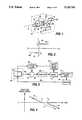
- FIG. 1illustrates a spacecraft 10 using a reaction wheel 12 affixed to an axle 14 mounted on bearings 16 supported by bearing blocks 18 and 20.
- a motor or torquer 22is coupled to wheel 12 for applying torque to the wheel under control of a torque command signal applied over a bus 24 from a control unit 26.
- Control unit 26generates the torque command signal based upon an attitude error signal applied over a bus 28 from an attitude sensor 30.
- Attitude sensor 30senses errors in the attitude of the body of spacecraft 10 about wheel axis 8.
- the bearing frictionincludes a fluid friction component that increases with increasing velocity. Another component of friction is the Coulomb component, which is constant and independent of speed.
- FIG. 2plots as 40 the torque T necessary to overcome Coulomb friction versus angular speed ⁇ for a wheel such as 12 of FIG. 1.
- the torque Thas a positive value and for negative ⁇ (the opposite direction of rotation), T has the same magnitude, but in the opposite direction.
- the constant component of Coulomb frictiontherefore exists down to and including zero rotational velocity.
- Static frictionwhich causes an increase in the force required to break the bearings away from a static or nonmoving condition, is generally small in the high quality bearings ordinarily used in conjunction with spacecraft reaction wheels. Static friction is suggested by dotted curve 42.
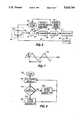
- FIG. 3illustrates, in simplified block diagram form, the control scheme described in the Pistiner patent.
- elements corresponding to those of FIG. 1are designated by the same reference numeral.
- a spacecraft illustrated by the system of FIG. 3uses attitude sensors and an integrator to produce a torque command signal on bus 24 for driving torquer 22 and reaction wheel 12.
- the integrated error signal on bus 24(which is the torque command signal) must be large enough to overcome the constant frictional force attributable to the Coulomb friction of the bearing.
- the torque command signalstill has a finite value which represents the amount of the torque command signal required to overcome the Coulomb friction while the wheel rotates.
- attitude errors of spacecraft 10can begin to accumulate.
- the attitude errorsare sensed by sensor 30 and an error signal is produced and applied over bus 28 to integrator 60 of FIG. 3.
- Attitude errorscontinue to accumulate while the wheel is stopped, because the error signals must be applied to the integrator for a finite length of time in order to first reduce the residual (Coulomb-attributable) component of torque command signal to zero, and then to increase the torque command signal to a value sufficient to overcome the Coulomb and static friction required for rotation in the opposite direction.
- the torques required for rotationare illustrated in FIG. 2.
- FIG. 4illustrates as a plot 70 the reaction wheel speed time history.
- the wheel speedis decreasing linearly toward zero speed before time T1.
- the direction of rotationshould simply reverse, and the wheel speed should increase in the opposite direction, as illustrated by dotted line 71.
- the wheelDue to Coulomb and static friction, the wheel remains stopped in the interval from time T1 until time T2. During this time, the control circuit reverses the torque command signal and increases its magnitude, until the torque is sufficient to overcome bearing friction at time T2, and the wheel then accelerates. At time T2, however, the torque command signal is large enough to cause a temporary overcorrection or overshoot of the path it would follow in the absence of friction illustrated as a curved portion 72 of plot 70.
- FIG. 5ais a plot of the results of a computer simulation of the attitude error and wheel speed of a spacecraft using reaction wheel attitude control without Pistiner's correction.
- Dotted curve 80represents wheel speed, which reverses direction of about 1000 seconds.
- Solid-line plot 82represents the attitude error.
- the effects of reaction-wheel bearing frictionresult in a peak attitude error of about 52 arc-seconds in the interval 1000 seconds to about 1020 seconds, during which time the reaction wheel is stopped. Immediately after 1020 seconds, the wheel accelerates, and a recovery attitude undershoot of eight arc-seconds occurs.
- the Pistiner arrangementrecognizes that the integrator output signal includes information relating to the magnitude of the Coulomb friction.
- an offset signal compensator illustrated in FIG. 3 as block 52generates an offset signal which is applied to an adder 54 and summed with the torque command signal to overcome the Coulomb friction.
- the magnitude of the offsetis established by sensing the wheel rotational speed by a sensor 50, noting the magnitude of the torque command signal at some wheel rotational speed in the range of 5 to 10 RPM, and performing calculations which are intended to subtract out the components which are attributable to known factors, such as orbital precession torques, whereupon the remaining magnitude of the torque command signal is assumed to correspond to value +T c of FIG. 2, the Coulomb attributable friction torque.
- FIG. 5billustrates the improved spacecraft attitude response when offset compensation is used in the Pistiner manner.
- FIG. 5bis similar to FIG. 5a, and corresponding plots are designated by the same reference numerals.
- the wheel speed represented by dashed line 80while not stopped for a sustained period near 1000 seconds as in the uncompensated case of FIG. 5a, is nevertheless perturbed.
- the spacecraft attitudebuilds up to an error of about 10 arc-seconds. This occurs because the offset does not exactly cancel the actual reaction wheel friction.
- integrated error signal components attributable to sources which are not taken into account in the offset calculationwill result in an incorrectly calculated torque command signal
- Such errorsmight arise due to environmental or internal disturbance forces an torques active on the spacecraft.
- a reaction wheel stabilized spacecraftincludes a spacecraft body, and at least one reaction wheel mounted for rotation about an axis on the body.
- a controllable torquing arrangementis coupled to the wheel for applying torque to the wheel in response to a torque command signal for accelerating or decelerating the reaction wheel and thereby transferring momentum to the spacecraft body.
- Sensorsare mounted on the spacecraft body for sensing the spacecraft attitude and for generating a signal in response to the deviation of the body from a desired rotational position about the axis.
- a control arrangementincludes an integrator coupled to the sensor for generating an attitude-sensitive component of the torque command signal.
- a summerreceives the attitude-sensitive component of the torque command signal and an alternating signal for generating a dithered torque command signal.
- FIG. 1illustrates a spacecraft including a reaction wheel attitude control system
- FIG. 2illustrates a plot of torque versus speed shown at the static and Coulomb friction relationship for the reaction wheel bearings of FIG. 1;
- FIG. 3illustrates in block diagram form a prior art Coulomb friction compensation arrangement
- FIG. 4conceptually illustrates the wheel speed compensation resulting from the use of the arrangement of FIG. 3 versus time
- FIGS. 5a and 5billustrates simulated spacecraft attitude and wheel speed for an uncompensated system, and for a system using the compensation of FIG. 3, respectively;
- FIG. 6is a block diagram of an attitude control arrangement in accordance with the invention.
- FIG. 7is an amplitude-time plot which illustrates a dither signal which may be used with a control system according to the invention.
- FIG. 8is a flow chart which may be associated with the arrangement of FIG. 6;
- FIG. 9is a plot similar to FIGS. 5a and 5b of attitude and wheel speed versus time for an arrangement in accordance with the invention.
- FIG. 6is a simplified block diagram of a spacecraft control system according to the invention. Elements of FIG. 6 corresponding to those of FIG. 3 are designated by the same reference numerals. FIG. 6 differs from FIG. 3 by the inclusion of a further control block designated 62, which is coupled to wheel speed sensor 50 for receiving wheel speed information, and which is also coupled to summer 54 for adding a further component to the torque command signal applied over bus 24 to torquer 22.
- a further control block designated 62which is coupled to wheel speed sensor 50 for receiving wheel speed information, and which is also coupled to summer 54 for adding a further component to the torque command signal applied over bus 24 to torquer 22.
- the bearings upon which the reaction wheel ridesare imperfect.
- these imperfectionsmay be considered to be lumped at a particular spot on the periphery of the bearing, so that as the reaction wheel is barely turning preparatory to stopping, it "falls into a hole" which is the imperfection in the bearing.
- energymust be imparted to the wheel which is greater than that required to rotate at constant velocity.
- Any additional energy added in the form of a torque command signalis integrated by the reaction wheel itself to produce an attitude error of the spacecraft.
- Such an attitude errorwill be sensed by sensor 30 and applied over bus 28 to integrator 60 of control circuit 26, and is integrated to produce an additional torque command component.
- control block 62 of FIG. 6generates a dither signal illustrated at 761 of FIG. 7.
- dither signal 761is a triangular signal having a peak amplitude of A and a period of T, whereupon the frequency is 2 ⁇ /T.
- the frequencyis selected to be much greater than the time constant of the spacecraft motion. More specifically, the frequency is selected to be greater than the highest damped natural frequency of the spacecraft body and of any flexible appendages thereof, such as masts or booms.
- the areas under the positive and negative excursions of dither signal 761 about zero amplitude during each half-cycleare equal, whereupon the net amplitude is zero.
- FIG. 8is a flow chart illustrating a control circuit which may be associated with dither control and generator block 62 of FIG. 6.
- the logic flowbegins at a start block 800 and proceeds to a block 802 which represents the reading of wheel speed ⁇ from wheel speed sensor 50 of FIG. 6.
- the logicflows to a decision block 804 in which the absolute value of wheel speed ⁇ is compared with a threshold.
- the threshold wheel speedmay be the same as that used for enabling offset compensator 52, or it may be a different wheel speed. If the absolute value of the wheel speed is greater than the threshold, the logic flows from decision block 804 by the NO path, and arrives at a block 806 which disables the dither generator (a part of block 62, not separately illustrated), whether or not it was previously enabled.
- the logicthen exits block 806 and returns to block 802.
- the logiccontinuously flows in a loop including blocks 802, 804 and 806.
- the logicwill exit from decision block 804 by the YES output, and will flow to a further block 808, which represents enabling of the dither generator.
- the logicthen returns to block 802 and continues its circulatory flow about the loop including blocks 802, 804 and 808 until such time as the wheel speed once again exceeds the threshold value.
- FIG. 9illustrates the reduction in attitude error attributable to the invention. Because of the dither signal, applied when the wheel speed falls below the 10 RPM threshold, the wheel never gets stuck so it maintains continuous control of the spacecraft attitude. The small residual error results from parameter uncertainties in the reaction wheel electronics and quantization of wheel speed by the logic shown in FIG. 8.
- the dither signalcan be sinusoidal, rectangular wave, or any other waveform which is symmetrical about the zero axis.
- the dither generatormay run continuously and its signal gated by a switch under the control of the logic of FIG. 8, or the generator may be disabled during those periods when it is not in use, and turned on to produce dither signal only when needed.
- the amplitude of the dither signalmay be made to vary in inverse relationship to the magnitude of the wheel speed, so that maximum amplitude is reached near zero wheel speed.
- the inventionmay apply to a momentum wheel if the wheel for any reason might be stopped in a normal operating mode.
Landscapes
- Engineering & Computer Science (AREA)
- Remote Sensing (AREA)
- Chemical & Material Sciences (AREA)
- Combustion & Propulsion (AREA)
- Radar, Positioning & Navigation (AREA)
- Aviation & Aerospace Engineering (AREA)
- Automation & Control Theory (AREA)
- Control Of Position, Course, Altitude, Or Attitude Of Moving Bodies (AREA)
Abstract
Description
The invention described herein was made in the performance of work under NASA Contract No. NAS5-32000 and is subject to provisions of Section 305 of the National Aeronautics and Space Act 1958, as amended (72 STAT. 2/35; 42 USC 247).
This invention relates to attitude control systems for spacecraft using reaction wheels, and more particularly to reduction in attitude errors during times when the wheel speed is reduced to zero and the direction of rotation is reversed.
Spacecraft have become important as platforms for communications or sensors. As a platform, the position or attitude of the spacecraft in space must be maintained constant relative to a distant object, such as the heavenly body which it orbits. In the absence of stabilization of the attitude of the spacecraft, the sensors or communication devices cannot be pointed in the desired direction with the desired accuracy.
Certain types of spacecraft are stabilized by spinning about an axis. With such spacecraft, the attitude of the spacecraft in inertial space remains essentially constant. While this may be desirable when a sensor is to be directed along its axis toward a distant inertially fixed target such as a star, it is less advantageous when directing an instrument towards a target moving relative to the spacecraft (i.e., on the Earth). The use of despun platforms on spin-stabilized spacecraft allow instruments or antennas to be pointed in directions other than along the spin axis. However, because the attitude of a spin-stabilized spacecraft remains constant in inertial space as the spacecraft orbits the Earth, constant articulation is required to orient the platform toward a point on Earth, which may be undesirable for some purposes.
The attitude of some spacecraft may be maintained by controlled firing of attitude control thrusters, as described in U.S. Pat. No. 3,866,025, issued Feb. 11, 1975 to Cavanagh. Such systems if used alone tend to be short-lived because the amount of expendable fuel is finite.
Magnetic torquers may be used for attitude control, as also described by Cavanagh. Current is allowed to flow through torquing coils located on the spacecraft body, to cause interaction with the Earth's magnetic field. Magnetic torquing cannot produce large torques for fast correction of attitude errors because the Earth's magnetic field in space is small in magnitude and uncertain in direction.
Spacecraft may also be stabilized by the use of one or more momentum or reaction wheels, either alone or in conjunction with thrusters and/or magnetic torquers. A common arrangement includes the use of three or more reaction wheels, whose axes are orthogonal, or at angles that provide components along the three orthogonal spacecraft axes, thereby providing three-axis control of the spacecraft attitude. Such a system is described in U.S. Pat. No. 3,999,729 issued Dec. 28, 1976 to Muhlfelder et al. It should be noted that momentum wheels differ from reaction wheels only in that they are operated at rotational speeds which are high enough to provide gyroscopic stiffness. Momentum wheels are not ordinarily reduced to near-zero speed, as are reaction wheels.
As described at length in U.S. Pat. No. 3,998,409 issued Dec. 21, 1976 to Pistiner, the roll and yaw axis reaction wheels of a three-axis momentum stabilized spacecraft interchange their stored angular momentum on a quarter-orbit basis. As a result, the roll and yaw axis reaction wheels reverse their speed directions twice per orbit. Attitude sensors on the spacecraft sense the attitude of the spacecraft and produce error signals equal to, or representative of the difference between the actual spacecraft attitude and its desired attitude. These error signals are integrated and are converted into appropriate torque command signals for each reaction wheel. The resulting reaction wheel rotations produce reaction torques on the spacecraft that reduce its attitude error. The bearings supporting the reaction wheel's rotation ordinarily are of very high quality, but are subject to frictional forces. FIG. 1 illustrates aspacecraft 10 using areaction wheel 12 affixed to anaxle 14 mounted onbearings 16 supported by bearingblocks torquer 22 is coupled towheel 12 for applying torque to the wheel under control of a torque command signal applied over abus 24 from acontrol unit 26.Control unit 26 generates the torque command signal based upon an attitude error signal applied over abus 28 from anattitude sensor 30.Attitude sensor 30 senses errors in the attitude of the body ofspacecraft 10 about wheel axis 8. When the wheel is rotating, the bearing friction includes a fluid friction component that increases with increasing velocity. Another component of friction is the Coulomb component, which is constant and independent of speed. FIG. 2 plots as 40 the torque T necessary to overcome Coulomb friction versus angular speed ω for a wheel such as 12 of FIG. 1. At positive values of ω, the torque T has a positive value and for negative ω (the opposite direction of rotation), T has the same magnitude, but in the opposite direction. The constant component of Coulomb friction therefore exists down to and including zero rotational velocity. Static friction, which causes an increase in the force required to break the bearings away from a static or nonmoving condition, is generally small in the high quality bearings ordinarily used in conjunction with spacecraft reaction wheels. Static friction is suggested bydotted curve 42.
FIG. 3 illustrates, in simplified block diagram form, the control scheme described in the Pistiner patent. In FIG. 3, elements corresponding to those of FIG. 1 are designated by the same reference numeral. A spacecraft illustrated by the system of FIG. 3 uses attitude sensors and an integrator to produce a torque command signal onbus 24 for drivingtorquer 22 andreaction wheel 12. In order to control the attitude error onbus 28 to zero, the integrated error signal on bus 24 (which is the torque command signal) must be large enough to overcome the constant frictional force attributable to the Coulomb friction of the bearing. Thus, as the wheel slows toward and reaches zero speed, the torque command signal still has a finite value which represents the amount of the torque command signal required to overcome the Coulomb friction while the wheel rotates. When the reaction wheel stops, the attitude of the spacecraft about the wheel axis is no longer controlled, and attitude errors ofspacecraft 10 can begin to accumulate. The attitude errors are sensed bysensor 30 and an error signal is produced and applied overbus 28 tointegrator 60 of FIG. 3. Attitude errors continue to accumulate while the wheel is stopped, because the error signals must be applied to the integrator for a finite length of time in order to first reduce the residual (Coulomb-attributable) component of torque command signal to zero, and then to increase the torque command signal to a value sufficient to overcome the Coulomb and static friction required for rotation in the opposite direction. The torques required for rotation are illustrated in FIG. 2. During the period of integration, the attitude error tends to increase, and therefore the sensed error signal increases more than it would if attitude control were continuous and Coulomb friction were absent. Consequently, at the moment when reaction wheel rotation in the opposite direction begins, the error signal tends to be larger than necessary, and as a result the torque command signal is excessive. This overly large torque command signal in turn causes an overcompensation for the accumulated attitude error. Thus, in the absence of compensation for Coulomb friction, large attitude errors may be expected. FIG. 4 illustrates as aplot 70 the reaction wheel speed time history. In FIG. 4, the wheel speed is decreasing linearly toward zero speed before time T1. Ideally, the direction of rotation should simply reverse, and the wheel speed should increase in the opposite direction, as illustrated bydotted line 71. Due to Coulomb and static friction, the wheel remains stopped in the interval from time T1 until time T2. During this time, the control circuit reverses the torque command signal and increases its magnitude, until the torque is sufficient to overcome bearing friction at time T2, and the wheel then accelerates. At time T2, however, the torque command signal is large enough to cause a temporary overcorrection or overshoot of the path it would follow in the absence of friction illustrated as acurved portion 72 ofplot 70.
FIG. 5a is a plot of the results of a computer simulation of the attitude error and wheel speed of a spacecraft using reaction wheel attitude control without Pistiner's correction. Dottedcurve 80 represents wheel speed, which reverses direction of about 1000 seconds. Solid-line plot 82 represents the attitude error. As illustrated, the effects of reaction-wheel bearing friction result in a peak attitude error of about 52 arc-seconds in theinterval 1000 seconds to about 1020 seconds, during which time the reaction wheel is stopped. Immediately after 1020 seconds, the wheel accelerates, and a recovery attitude undershoot of eight arc-seconds occurs.
The Pistiner arrangement recognizes that the integrator output signal includes information relating to the magnitude of the Coulomb friction. In the Pistiner arrangement, an offset signal compensator illustrated in FIG. 3 asblock 52 generates an offset signal which is applied to anadder 54 and summed with the torque command signal to overcome the Coulomb friction. The magnitude of the offset is established by sensing the wheel rotational speed by asensor 50, noting the magnitude of the torque command signal at some wheel rotational speed in the range of 5 to 10 RPM, and performing calculations which are intended to subtract out the components which are attributable to known factors, such as orbital precession torques, whereupon the remaining magnitude of the torque command signal is assumed to correspond to value +Tc of FIG. 2, the Coulomb attributable friction torque. Once the magnitude of the component of the torque command signal attributable to the Coulomb bearing friction is found, its value is doubled to 2Tc (since the value must be reduced to zero and then increased back to the same value in the opposite direction), inverted in phase (-2Tc) and then added (in summer 54) to the torque command signal. When - 2Tr is summed with a torque command signal including a component of +Tc, the resulting summed torque command signal includes a reversed component with an amplitude -Tc, which is exactly what is necessary to overcome the Coulomb friction when wheel reversal takes place. This technique is effective in reducing attitude errors. FIG. 5b illustrates the improved spacecraft attitude response when offset compensation is used in the Pistiner manner. FIG. 5b is similar to FIG. 5a, and corresponding plots are designated by the same reference numerals. As illustrated in FIG. 5b, the wheel speed represented by dashedline 80, while not stopped for a sustained period near 1000 seconds as in the uncompensated case of FIG. 5a, is nevertheless perturbed. The spacecraft attitude builds up to an error of about 10 arc-seconds. This occurs because the offset does not exactly cancel the actual reaction wheel friction. In the Pistiner arrangement, integrated error signal components attributable to sources which are not taken into account in the offset calculation will result in an incorrectly calculated torque command signal Such errors might arise due to environmental or internal disturbance forces an torques active on the spacecraft. Also, the effective reversal of Tc at a wheel rotational velocity of ω=10 RPM itself tends to perturb the attitude, by slowing the wheel by more than the expected amount, which again contributes to attitude error.
If the offset signal which is added to the torque command signal in the Pistiner arrangement deviates in magnitude from the true value required for the overcoming of friction, the result will be similar to that which occurred in the absence of compensation, namely attitude errors due to undercompensation or overcompensation. An improved reaction wheel attitude control arrangement is desired.
A reaction wheel stabilized spacecraft according to the invention includes a spacecraft body, and at least one reaction wheel mounted for rotation about an axis on the body. A controllable torquing arrangement is coupled to the wheel for applying torque to the wheel in response to a torque command signal for accelerating or decelerating the reaction wheel and thereby transferring momentum to the spacecraft body. Sensors are mounted on the spacecraft body for sensing the spacecraft attitude and for generating a signal in response to the deviation of the body from a desired rotational position about the axis. A control arrangement includes an integrator coupled to the sensor for generating an attitude-sensitive component of the torque command signal. A summer receives the attitude-sensitive component of the torque command signal and an alternating signal for generating a dithered torque command signal.
FIG. 1 illustrates a spacecraft including a reaction wheel attitude control system;
FIG. 2 illustrates a plot of torque versus speed shown at the static and Coulomb friction relationship for the reaction wheel bearings of FIG. 1;
FIG. 3 illustrates in block diagram form a prior art Coulomb friction compensation arrangement;
FIG. 4 conceptually illustrates the wheel speed compensation resulting from the use of the arrangement of FIG. 3 versus time;
FIGS. 5a and 5b illustrates simulated spacecraft attitude and wheel speed for an uncompensated system, and for a system using the compensation of FIG. 3, respectively;
FIG. 6 is a block diagram of an attitude control arrangement in accordance with the invention;
FIG. 7 is an amplitude-time plot which illustrates a dither signal which may be used with a control system according to the invention;
FIG. 8 is a flow chart which may be associated with the arrangement of FIG. 6; and
FIG. 9 is a plot similar to FIGS. 5a and 5b of attitude and wheel speed versus time for an arrangement in accordance with the invention.
FIG. 6 is a simplified block diagram of a spacecraft control system according to the invention. Elements of FIG. 6 corresponding to those of FIG. 3 are designated by the same reference numerals. FIG. 6 differs from FIG. 3 by the inclusion of a further control block designated 62, which is coupled towheel speed sensor 50 for receiving wheel speed information, and which is also coupled tosummer 54 for adding a further component to the torque command signal applied overbus 24 totorquer 22.
At the microscopic level, the bearings upon which the reaction wheel rides are imperfect. Conceptually, these imperfections may be considered to be lumped at a particular spot on the periphery of the bearing, so that as the reaction wheel is barely turning preparatory to stopping, it "falls into a hole" which is the imperfection in the bearing. In order to leave the hole, energy must be imparted to the wheel which is greater than that required to rotate at constant velocity. Any additional energy added in the form of a torque command signal is integrated by the reaction wheel itself to produce an attitude error of the spacecraft. Such an attitude error will be sensed bysensor 30 and applied overbus 28 tointegrator 60 ofcontrol circuit 26, and is integrated to produce an additional torque command component.
In accordance with an aspect of the invention,control block 62 of FIG. 6 generates a dither signal illustrated at 761 of FIG. 7. In FIG. 7,dither signal 761 is a triangular signal having a peak amplitude of A and a period of T, whereupon the frequency is 2π/T. The frequency is selected to be much greater than the time constant of the spacecraft motion. More specifically, the frequency is selected to be greater than the highest damped natural frequency of the spacecraft body and of any flexible appendages thereof, such as masts or booms. In addition, the areas under the positive and negative excursions ofdither signal 761 about zero amplitude during each half-cycle are equal, whereupon the net amplitude is zero. Consequently, energy which is added during one half-cycle of dither is subtracted during the other half-cycle dither, and no net energy is added. Since no net energy is added, the reaction wheel integrates the dither signal to zero, which creates no integrated attitude error. However, during one or the other half-cycle of the dither, sufficient energy is available to overcome the Coulomb friction and to start the wheel into rotation.
FIG. 8 is a flow chart illustrating a control circuit which may be associated with dither control andgenerator block 62 of FIG. 6. In FIG. 8, the logic flow begins at astart block 800 and proceeds to ablock 802 which represents the reading of wheel speed ω fromwheel speed sensor 50 of FIG. 6. The logic flows to adecision block 804 in which the absolute value of wheel speed ω is compared with a threshold. The threshold wheel speed may be the same as that used for enabling offsetcompensator 52, or it may be a different wheel speed. If the absolute value of the wheel speed is greater than the threshold, the logic flows fromdecision block 804 by the NO path, and arrives at ablock 806 which disables the dither generator (a part ofblock 62, not separately illustrated), whether or not it was previously enabled. The logic then exitsblock 806 and returns to block 802. The logic continuously flows in aloop including blocks decision block 804 by the YES output, and will flow to afurther block 808, which represents enabling of the dither generator. The logic then returns to block 802 and continues its circulatory flow about theloop including blocks
FIG. 9 illustrates the reduction in attitude error attributable to the invention. Because of the dither signal, applied when the wheel speed falls below the 10 RPM threshold, the wheel never gets stuck so it maintains continuous control of the spacecraft attitude. The small residual error results from parameter uncertainties in the reaction wheel electronics and quantization of wheel speed by the logic shown in FIG. 8.
Other embodiments of the invention will be apparent to those skilled in the art. For example, the dither signal can be sinusoidal, rectangular wave, or any other waveform which is symmetrical about the zero axis. The dither generator may run continuously and its signal gated by a switch under the control of the logic of FIG. 8, or the generator may be disabled during those periods when it is not in use, and turned on to produce dither signal only when needed. The amplitude of the dither signal may be made to vary in inverse relationship to the magnitude of the wheel speed, so that maximum amplitude is reached near zero wheel speed. The invention may apply to a momentum wheel if the wheel for any reason might be stopped in a normal operating mode.
Claims (6)
1. A reaction-wheel stabilized spacecraft, comprising:
a spacecraft body;
at least one reaction wheel mounted for rotation about an axis on said spacecraft body;
controllable torquing means coupled to said spacecraft body and to said wheel for applying torque to said wheel in response to a torque command signal for acceleration or deceleration thereof for transferring momentum to said spacecraft body;
sensing means mounted on said spacecraft body for sensing the attitude of said spacecraft body, and for generating a signal in response to deviation of said spacecraft body from a desired rotational position about said axis;
control means including integrating means coupled to said sensing means for generating an attitude-sensitive component of said torque command signal;
summing means including a first input port coupled to said control means and an output port coupled to said torquing means, for receiving said attitude-sensitive component of said torque command signal from said control means, and further including a second input port, for combining said attitude-sensitive component of said torque command signal with a signal applied to said second input port of said summing means to generate said torque command signal; and
alternating signal generating means coupled to said second input port of said summing means for generating a signal of alternating polarity and for applying said signal of alternating polarity to said second input port of said summing means, whereby said torque command signal may include an alternating component.
2. A spacecraft according to claim 1 wherein said signal of alternating polarity alternates at a frequency which is higher than the highest dominant damped material frequency associated with the spacecraft and any flexible appendage.
3. A spacecraft according to claim 1 wherein said alternating signal generating means further comprises:
wheel speed sensing means coupled to said reaction wheel for sensing the rotational speed thereof and for generating a speed signal representative of said rotational speed;
amplitude control means coupled to said wheel speed sensing means and responsive to said speed signal for causing said signal of alternating polarity to be applied to said second input port of said summing means when the wheel speed represented by said speed signal is relatively low, and for reducing the magnitude of said signal of alternating polarity when the wheel speed represented by said speed signal is relatively high.
4. A spacecraft according to claim 3, wherein said amplitude control means comprises switch means for coupling said signal of alternating polarity to said second input port of said summing means with full amplitude when said wheel speed is relatively low, and for decoupling said signal of alternating polarity from said second input port of said summing means when said wheel speed is relatively high, for thereby reducing the amplitude to zero.
5. A method for controlling the attitude of a spacecraft about the axis of a bearing-mounted wheel, comprising the steps of:
sensing the attitude of said spacecraft about the axis of a reaction wheel to generate an error signal;
integrating said error signal to produce a torque command signal;
torquing said reaction wheel in response to said torque command signal in a manner tending to stabilize said attitude of said spacecraft, whereupon the direction of rotation of said reaction wheel may from time to time reverse;
sensing the rotational speed of said reaction wheel; and
at rotational speeds near zero rotational speed, adding an alternating-polarity signal to said torque command signal.
6. A method according to claim 5 wherein said step of adding includes the step of controlling said alternating-polarity signal so that its average value is zero.
Priority Applications (5)
| Application Number | Priority Date | Filing Date | Title |
|---|---|---|---|
| US07/454,651US5020745A (en) | 1989-12-20 | 1989-12-20 | Reaction wheel fricton compensation using dither |
| FR909012509AFR2655942B1 (en) | 1989-12-20 | 1990-10-10 | DEVICE FOR CONTROLLING THE POSITION OF A SPACE MACHINE WITH COMPENSATION FOR THE FRICTION OF A REACTION WHEEL. |
| DE4032263ADE4032263A1 (en) | 1989-12-20 | 1990-10-11 | REACTION WHEEL FRICTION COMPENSATION |
| JP2279524AJPH03193599A (en) | 1989-12-20 | 1990-10-19 | Reaction wheel friction compasated space ship |
| GB9022824AGB2239329B (en) | 1989-12-20 | 1990-10-19 | Reaction wheel stabilised spacecraft |
Applications Claiming Priority (1)
| Application Number | Priority Date | Filing Date | Title |
|---|---|---|---|
| US07/454,651US5020745A (en) | 1989-12-20 | 1989-12-20 | Reaction wheel fricton compensation using dither |
Publications (1)
| Publication Number | Publication Date |
|---|---|
| US5020745Atrue US5020745A (en) | 1991-06-04 |
Family
ID=23805506
Family Applications (1)
| Application Number | Title | Priority Date | Filing Date |
|---|---|---|---|
| US07/454,651Expired - LifetimeUS5020745A (en) | 1989-12-20 | 1989-12-20 | Reaction wheel fricton compensation using dither |
Country Status (5)
| Country | Link |
|---|---|
| US (1) | US5020745A (en) |
| JP (1) | JPH03193599A (en) |
| DE (1) | DE4032263A1 (en) |
| FR (1) | FR2655942B1 (en) |
| GB (1) | GB2239329B (en) |
Cited By (25)
| Publication number | Priority date | Publication date | Assignee | Title |
|---|---|---|---|---|
| FR2679345A1 (en)* | 1991-07-19 | 1993-01-22 | Gen Electric | System and process for controlling spacecraft attitude |
| US5211360A (en)* | 1991-06-26 | 1993-05-18 | Fairchild Space And Defense Corporation | Spacecraft thermal disturbance control system |
| US5248118A (en)* | 1992-05-13 | 1993-09-28 | General Electric Co. | Spacecraft attitude control system with reaction wheel bearing protection |
| US5935176A (en)* | 1996-11-22 | 1999-08-10 | Lockheed Martin Corporation | Momentum wheel oscillation filter |
| EP0937644A2 (en) | 1998-02-23 | 1999-08-25 | Space Systems/Loral, Inc. | Space craft axis stabilizer apparatus, system and method |
| US6285928B1 (en) | 2000-01-06 | 2001-09-04 | Space Systems/Loral, Inc. | Onboard attitude control using reaction wheels |
| US20060198474A1 (en)* | 1999-04-16 | 2006-09-07 | Parker Vision, Inc. | Method and system for down-converting and electromagnetic signal, and transforms for same |
| US20070041435A1 (en)* | 2002-07-18 | 2007-02-22 | Parkervision, Inc. | Networking methods and systems |
| US20070293182A1 (en)* | 2000-04-14 | 2007-12-20 | Parkervision, Inc. | Apparatus, system, and method for down converting and up converting electromagnetic signals |
| US20080182544A1 (en)* | 1998-10-21 | 2008-07-31 | Parkervision, Inc. | Methods and Systems for Down-Converting a Signal Using a Complementary Transistor Structure |
| US20080270170A1 (en)* | 2002-07-18 | 2008-10-30 | Parkervision, Inc. | Networking Methods and Systems |
| US20090221257A1 (en)* | 1998-10-21 | 2009-09-03 | Parkervision, Inc. | Method and System For Down-Converting An Electromagnetic Signal, And Transforms For Same, And Aperture Relationships |
| US20100133374A1 (en)* | 2008-12-01 | 2010-06-03 | Geswender Chris E | Projectile navigation enhancement method |
| US7826817B2 (en) | 1998-10-21 | 2010-11-02 | Parker Vision, Inc. | Applications of universal frequency translation |
| US7894789B2 (en) | 1999-04-16 | 2011-02-22 | Parkervision, Inc. | Down-conversion of an electromagnetic signal with feedback control |
| US7929638B2 (en) | 1999-04-16 | 2011-04-19 | Parkervision, Inc. | Wireless local area network (WLAN) using universal frequency translation technology including multi-phase embodiments |
| US7991815B2 (en) | 2000-11-14 | 2011-08-02 | Parkervision, Inc. | Methods, systems, and computer program products for parallel correlation and applications thereof |
| US8019291B2 (en) | 1998-10-21 | 2011-09-13 | Parkervision, Inc. | Method and system for frequency down-conversion and frequency up-conversion |
| US8036304B2 (en) | 1999-04-16 | 2011-10-11 | Parkervision, Inc. | Apparatus and method of differential IQ frequency up-conversion |
| US8077797B2 (en) | 1999-04-16 | 2011-12-13 | Parkervision, Inc. | Method, system, and apparatus for balanced frequency up-conversion of a baseband signal |
| US8233855B2 (en) | 1998-10-21 | 2012-07-31 | Parkervision, Inc. | Up-conversion based on gated information signal |
| US8295406B1 (en) | 1999-08-04 | 2012-10-23 | Parkervision, Inc. | Universal platform module for a plurality of communication protocols |
| US8446994B2 (en) | 2001-11-09 | 2013-05-21 | Parkervision, Inc. | Gain control in a communication channel |
| US8918236B2 (en) | 2011-06-24 | 2014-12-23 | Honeywell International Inc. | Methods and systems for adjusting attitude using reaction wheels |
| US20160052624A1 (en)* | 2011-02-04 | 2016-02-25 | Borealis Technical Limited | Method of Operating Aircraft Drive To Move an Aircraft Under Adverse Ground Conditions |
Families Citing this family (2)
| Publication number | Priority date | Publication date | Assignee | Title |
|---|---|---|---|---|
| DE19924908B4 (en)* | 1999-05-31 | 2008-05-29 | Astrium Gmbh | Three-axis attitude determination method for a low-flying satellite |
| KR200481996Y1 (en)* | 2014-11-24 | 2016-12-05 | 오세기 | Paper Doll With Articulation Mechanism |
Citations (17)
| Publication number | Priority date | Publication date | Assignee | Title |
|---|---|---|---|---|
| US3350033A (en)* | 1965-10-21 | 1967-10-31 | Gerald I Goldberg | Reaction wheel scanner |
| US3424401A (en)* | 1966-10-18 | 1969-01-28 | Kent M Maurer | Method and means for attitude control of space vehicles |
| US3493194A (en)* | 1967-07-27 | 1970-02-03 | Nasa | Spacecraft experiment pointing and attitude control system |
| US3591108A (en)* | 1967-01-27 | 1971-07-06 | Rca Corp | Control system for spinning bodies |
| US3866025A (en)* | 1972-03-17 | 1975-02-11 | Rca Corp | Spacecraft attitude control system |
| US3968352A (en)* | 1974-05-17 | 1976-07-06 | Sperry Rand Corporation | Torque control system for reaction wheel assemblies and the like |
| US3998409A (en)* | 1975-03-11 | 1976-12-21 | Rca Corporation | Minimization of spacecraft attitude error due to wheel speed reversal |
| US3999729A (en)* | 1975-03-20 | 1976-12-28 | Rca Corporation | Backup wheel for a three axis reaction wheel spacecraft |
| US4071211A (en)* | 1976-09-23 | 1978-01-31 | Rca Corporation | Momentum biased active three-axis satellite attitude control system |
| US4211452A (en)* | 1977-03-15 | 1980-07-08 | Societe Nationale Industrielle Aerospatiale | Inertia wheel |
| US4272045A (en)* | 1979-03-29 | 1981-06-09 | Rca Corporation | Nutation damping in a dual-spin spacecraft |
| US4361073A (en)* | 1974-03-18 | 1982-11-30 | Chandler Evans Inc. | Sub-critical time modulated control mechanism |
| US4470562A (en)* | 1965-10-22 | 1984-09-11 | The United States Of America As Represented By The Secretary Of The Navy | Polaris guidance system |
| US4521855A (en)* | 1981-07-27 | 1985-06-04 | Ford Aerospace & Communications Corporation | Electronic on-orbit roll/yaw satellite control |
| US4567564A (en)* | 1980-08-19 | 1986-01-28 | Messerschmitt-Bolkow-Blohm Gesellschaft Mit Beschrankter Haftung | Arrangement for the attitude stabilization of flexible vehicles with weakly-dampened structural vibrations and discontinuous control intervention |
| US4752884A (en)* | 1985-07-18 | 1988-06-21 | Hughes Aircraft Company | Precision platform pointing controller for a dual-spin spacecraft |
| US4767084A (en)* | 1986-09-18 | 1988-08-30 | Ford Aerospace & Communications Corporation | Autonomous stationkeeping for three-axis stabilized spacecraft |
Family Cites Families (7)
| Publication number | Priority date | Publication date | Assignee | Title |
|---|---|---|---|---|
| GB171214A (en)* | 1920-08-24 | 1921-11-17 | Francis Albert Arthur Ellmore | A fault indicator for use in connection with electric ignition systems |
| GB544601A (en)* | 1940-03-14 | 1942-04-20 | British Thomson Houston Co Ltd | Improvements in and relating to electric register control systems |
| GB605971A (en)* | 1944-12-30 | 1948-08-04 | British Thomson Houston Co Ltd | Improvements relating to speed governors for rotary wing aircraft |
| US4084772A (en)* | 1976-01-28 | 1978-04-18 | Rca Corporation | Roll/yaw body steering for momentum biased spacecraft |
| US4294420A (en)* | 1978-01-30 | 1981-10-13 | Matra | Attitude control systems for space vehicles |
| DE3590662T1 (en)* | 1984-12-22 | 1987-02-19 | ||
| US4843294A (en)* | 1987-12-01 | 1989-06-27 | Ford Aerospace & Communications Corporation | Solar array stepping to minimize array excitation |
- 1989
- 1989-12-20USUS07/454,651patent/US5020745A/ennot_activeExpired - Lifetime
- 1990
- 1990-10-10FRFR909012509Apatent/FR2655942B1/ennot_activeExpired - Lifetime
- 1990-10-11DEDE4032263Apatent/DE4032263A1/ennot_activeCeased
- 1990-10-19JPJP2279524Apatent/JPH03193599A/enactivePending
- 1990-10-19GBGB9022824Apatent/GB2239329B/ennot_activeExpired - Fee Related
Patent Citations (17)
| Publication number | Priority date | Publication date | Assignee | Title |
|---|---|---|---|---|
| US3350033A (en)* | 1965-10-21 | 1967-10-31 | Gerald I Goldberg | Reaction wheel scanner |
| US4470562A (en)* | 1965-10-22 | 1984-09-11 | The United States Of America As Represented By The Secretary Of The Navy | Polaris guidance system |
| US3424401A (en)* | 1966-10-18 | 1969-01-28 | Kent M Maurer | Method and means for attitude control of space vehicles |
| US3591108A (en)* | 1967-01-27 | 1971-07-06 | Rca Corp | Control system for spinning bodies |
| US3493194A (en)* | 1967-07-27 | 1970-02-03 | Nasa | Spacecraft experiment pointing and attitude control system |
| US3866025A (en)* | 1972-03-17 | 1975-02-11 | Rca Corp | Spacecraft attitude control system |
| US4361073A (en)* | 1974-03-18 | 1982-11-30 | Chandler Evans Inc. | Sub-critical time modulated control mechanism |
| US3968352A (en)* | 1974-05-17 | 1976-07-06 | Sperry Rand Corporation | Torque control system for reaction wheel assemblies and the like |
| US3998409A (en)* | 1975-03-11 | 1976-12-21 | Rca Corporation | Minimization of spacecraft attitude error due to wheel speed reversal |
| US3999729A (en)* | 1975-03-20 | 1976-12-28 | Rca Corporation | Backup wheel for a three axis reaction wheel spacecraft |
| US4071211A (en)* | 1976-09-23 | 1978-01-31 | Rca Corporation | Momentum biased active three-axis satellite attitude control system |
| US4211452A (en)* | 1977-03-15 | 1980-07-08 | Societe Nationale Industrielle Aerospatiale | Inertia wheel |
| US4272045A (en)* | 1979-03-29 | 1981-06-09 | Rca Corporation | Nutation damping in a dual-spin spacecraft |
| US4567564A (en)* | 1980-08-19 | 1986-01-28 | Messerschmitt-Bolkow-Blohm Gesellschaft Mit Beschrankter Haftung | Arrangement for the attitude stabilization of flexible vehicles with weakly-dampened structural vibrations and discontinuous control intervention |
| US4521855A (en)* | 1981-07-27 | 1985-06-04 | Ford Aerospace & Communications Corporation | Electronic on-orbit roll/yaw satellite control |
| US4752884A (en)* | 1985-07-18 | 1988-06-21 | Hughes Aircraft Company | Precision platform pointing controller for a dual-spin spacecraft |
| US4767084A (en)* | 1986-09-18 | 1988-08-30 | Ford Aerospace & Communications Corporation | Autonomous stationkeeping for three-axis stabilized spacecraft |
Cited By (47)
| Publication number | Priority date | Publication date | Assignee | Title |
|---|---|---|---|---|
| US5211360A (en)* | 1991-06-26 | 1993-05-18 | Fairchild Space And Defense Corporation | Spacecraft thermal disturbance control system |
| FR2679345A1 (en)* | 1991-07-19 | 1993-01-22 | Gen Electric | System and process for controlling spacecraft attitude |
| US5201833A (en)* | 1991-07-19 | 1993-04-13 | General Electric Company | Attitude control system with reaction wheel friction compensation |
| US5248118A (en)* | 1992-05-13 | 1993-09-28 | General Electric Co. | Spacecraft attitude control system with reaction wheel bearing protection |
| FR2693282A1 (en)* | 1992-05-13 | 1994-01-07 | Gillette Co | System and method for controlling the attitude of a spacecraft. |
| US5935176A (en)* | 1996-11-22 | 1999-08-10 | Lockheed Martin Corporation | Momentum wheel oscillation filter |
| EP0937644A2 (en) | 1998-02-23 | 1999-08-25 | Space Systems/Loral, Inc. | Space craft axis stabilizer apparatus, system and method |
| FR2775251A1 (en) | 1998-02-23 | 1999-08-27 | Loral Space Systems Inc | CONFIGURATION OF ASSEMBLY OF MULTI-PURPOSE THRUSTER |
| US20080182544A1 (en)* | 1998-10-21 | 2008-07-31 | Parkervision, Inc. | Methods and Systems for Down-Converting a Signal Using a Complementary Transistor Structure |
| US8233855B2 (en) | 1998-10-21 | 2012-07-31 | Parkervision, Inc. | Up-conversion based on gated information signal |
| US7936022B2 (en) | 1998-10-21 | 2011-05-03 | Parkervision, Inc. | Method and circuit for down-converting a signal |
| US8190108B2 (en) | 1998-10-21 | 2012-05-29 | Parkervision, Inc. | Method and system for frequency up-conversion |
| US8340618B2 (en) | 1998-10-21 | 2012-12-25 | Parkervision, Inc. | Method and system for down-converting an electromagnetic signal, and transforms for same, and aperture relationships |
| US8190116B2 (en) | 1998-10-21 | 2012-05-29 | Parker Vision, Inc. | Methods and systems for down-converting a signal using a complementary transistor structure |
| US20080272441A1 (en)* | 1998-10-21 | 2008-11-06 | Parkervision, Inc. | Method and circuit for down-converting a signal |
| US20090221257A1 (en)* | 1998-10-21 | 2009-09-03 | Parkervision, Inc. | Method and System For Down-Converting An Electromagnetic Signal, And Transforms For Same, And Aperture Relationships |
| US8160534B2 (en) | 1998-10-21 | 2012-04-17 | Parkervision, Inc. | Applications of universal frequency translation |
| US8019291B2 (en) | 1998-10-21 | 2011-09-13 | Parkervision, Inc. | Method and system for frequency down-conversion and frequency up-conversion |
| US7937059B2 (en) | 1998-10-21 | 2011-05-03 | Parkervision, Inc. | Converting an electromagnetic signal via sub-sampling |
| US7826817B2 (en) | 1998-10-21 | 2010-11-02 | Parker Vision, Inc. | Applications of universal frequency translation |
| US7865177B2 (en)* | 1998-10-21 | 2011-01-04 | Parkervision, Inc. | Method and system for down-converting an electromagnetic signal, and transforms for same, and aperture relationships |
| US8223898B2 (en) | 1999-04-16 | 2012-07-17 | Parkervision, Inc. | Method and system for down-converting an electromagnetic signal, and transforms for same |
| US8224281B2 (en) | 1999-04-16 | 2012-07-17 | Parkervision, Inc. | Down-conversion of an electromagnetic signal with feedback control |
| US7894789B2 (en) | 1999-04-16 | 2011-02-22 | Parkervision, Inc. | Down-conversion of an electromagnetic signal with feedback control |
| US8594228B2 (en) | 1999-04-16 | 2013-11-26 | Parkervision, Inc. | Apparatus and method of differential IQ frequency up-conversion |
| US20060198474A1 (en)* | 1999-04-16 | 2006-09-07 | Parker Vision, Inc. | Method and system for down-converting and electromagnetic signal, and transforms for same |
| US8229023B2 (en) | 1999-04-16 | 2012-07-24 | Parkervision, Inc. | Wireless local area network (WLAN) using universal frequency translation technology including multi-phase embodiments |
| US8036304B2 (en) | 1999-04-16 | 2011-10-11 | Parkervision, Inc. | Apparatus and method of differential IQ frequency up-conversion |
| US8077797B2 (en) | 1999-04-16 | 2011-12-13 | Parkervision, Inc. | Method, system, and apparatus for balanced frequency up-conversion of a baseband signal |
| US7724845B2 (en) | 1999-04-16 | 2010-05-25 | Parkervision, Inc. | Method and system for down-converting and electromagnetic signal, and transforms for same |
| US7929638B2 (en) | 1999-04-16 | 2011-04-19 | Parkervision, Inc. | Wireless local area network (WLAN) using universal frequency translation technology including multi-phase embodiments |
| US8295406B1 (en) | 1999-08-04 | 2012-10-23 | Parkervision, Inc. | Universal platform module for a plurality of communication protocols |
| US6285928B1 (en) | 2000-01-06 | 2001-09-04 | Space Systems/Loral, Inc. | Onboard attitude control using reaction wheels |
| US7822401B2 (en) | 2000-04-14 | 2010-10-26 | Parkervision, Inc. | Apparatus and method for down-converting electromagnetic signals by controlled charging and discharging of a capacitor |
| US20070293182A1 (en)* | 2000-04-14 | 2007-12-20 | Parkervision, Inc. | Apparatus, system, and method for down converting and up converting electromagnetic signals |
| US8295800B2 (en) | 2000-04-14 | 2012-10-23 | Parkervision, Inc. | Apparatus and method for down-converting electromagnetic signals by controlled charging and discharging of a capacitor |
| US7991815B2 (en) | 2000-11-14 | 2011-08-02 | Parkervision, Inc. | Methods, systems, and computer program products for parallel correlation and applications thereof |
| US8446994B2 (en) | 2001-11-09 | 2013-05-21 | Parkervision, Inc. | Gain control in a communication channel |
| US8407061B2 (en) | 2002-07-18 | 2013-03-26 | Parkervision, Inc. | Networking methods and systems |
| US20070041435A1 (en)* | 2002-07-18 | 2007-02-22 | Parkervision, Inc. | Networking methods and systems |
| US8160196B2 (en) | 2002-07-18 | 2012-04-17 | Parkervision, Inc. | Networking methods and systems |
| US20080270170A1 (en)* | 2002-07-18 | 2008-10-30 | Parkervision, Inc. | Networking Methods and Systems |
| US20100133374A1 (en)* | 2008-12-01 | 2010-06-03 | Geswender Chris E | Projectile navigation enhancement method |
| US8519313B2 (en)* | 2008-12-01 | 2013-08-27 | Raytheon Company | Projectile navigation enhancement method |
| US20160052624A1 (en)* | 2011-02-04 | 2016-02-25 | Borealis Technical Limited | Method of Operating Aircraft Drive To Move an Aircraft Under Adverse Ground Conditions |
| US10106249B2 (en)* | 2011-02-04 | 2018-10-23 | Borealis Technical Limited | Method of operating aircraft drive to move an aircraft under adverse ground conditions |
| US8918236B2 (en) | 2011-06-24 | 2014-12-23 | Honeywell International Inc. | Methods and systems for adjusting attitude using reaction wheels |
Also Published As
| Publication number | Publication date |
|---|---|
| FR2655942B1 (en) | 1992-04-30 |
| FR2655942A1 (en) | 1991-06-21 |
| GB9022824D0 (en) | 1990-12-05 |
| GB2239329A (en) | 1991-06-26 |
| JPH03193599A (en) | 1991-08-23 |
| DE4032263A1 (en) | 1991-06-27 |
| GB2239329B (en) | 1993-12-01 |
Similar Documents
| Publication | Publication Date | Title |
|---|---|---|
| US5020745A (en) | Reaction wheel fricton compensation using dither | |
| US4230294A (en) | Closed loop roll control for momentum biased satellites | |
| US5535965A (en) | Three-axis stabilized, earth-oriented satellite and a corresponding sun and earth acquisition process | |
| US5788188A (en) | Control of the attitude of a satellite in low orbit involving solar acquisition | |
| US5279483A (en) | Attitude control system for a three-axis stabilized satellite especially a remote sensing satellite | |
| US4294420A (en) | Attitude control systems for space vehicles | |
| CA1285256C (en) | Method for spinning up a three-axis controlled spacecraft | |
| US5826829A (en) | Spacecraft control system with a trihedral momentum bias wheel configuration | |
| JPS6047159B2 (en) | Satellite attitude control device | |
| JPH07137698A (en) | Attitude control of a spinning spacecraft | |
| US6745984B2 (en) | Method of controlling the attitude and stabilization of a satellite in low orbit | |
| CA1282393C (en) | Pivot actuated nutation damping system for a dual-spin spacecraft | |
| US4424948A (en) | Magnetically torqued nutation damping | |
| US5067673A (en) | Essentially passive method for inverting the orientation of a dual spin spacecraft | |
| JPH09323700A (en) | Sun / Earth capture without thrusters | |
| EP2390189B1 (en) | Methods and systems for reducing angular velocity using a gyroscope array | |
| US4096427A (en) | Nutation damping in dual-spin stabilized devices | |
| US6196502B1 (en) | Attitude control of spinning spacecraft with counterspun controls platform | |
| US9617015B2 (en) | Method of commanding an attitude control system and attitude control system of a space vehicle | |
| US5944761A (en) | Variable periodic disturbance rejection filter | |
| Stetson Jr | Reaction wheel fricton compensation using dither | |
| Steyn | A dual-wheel multi-mode spacecraft actuator for near-minimum-time large angle slew maneuvers | |
| Perkel | Stabilite–A Three-Axis Attitude Control System Utilizing a Single Reaction Wheel | |
| KR102464558B1 (en) | Satellite performing momentum dumping of reaction wheel through maneuvering of satellite, and method of momentum dumping of the reaction wheel of the satellite | |
| JP4283490B2 (en) | Satellite attitude and stability control method in low orbit |
Legal Events
| Date | Code | Title | Description |
|---|---|---|---|
| AS | Assignment | Owner name:GENERAL ELECTRIC COMPANY, A CORP. OF NY, NEW YORK Free format text:ASSIGNMENT OF ASSIGNORS INTEREST.;ASSIGNOR:STETSON, JOHN B. JR.;REEL/FRAME:005202/0683 Effective date:19891218 | |
| STCF | Information on status: patent grant | Free format text:PATENTED CASE | |
| CC | Certificate of correction | ||
| AS | Assignment | Owner name:MARTIN MARIETTA CORPORATION, MARYLAND Free format text:ASSIGNMENT OF ASSIGNORS INTEREST;ASSIGNOR:GENERAL ELECTRIC COMPANY;REEL/FRAME:007046/0736 Effective date:19940322 | |
| FEPP | Fee payment procedure | Free format text:PAYOR NUMBER ASSIGNED (ORIGINAL EVENT CODE: ASPN); ENTITY STATUS OF PATENT OWNER: LARGE ENTITY | |
| FPAY | Fee payment | Year of fee payment:4 | |
| AS | Assignment | Owner name:LOCKHEED MARTIN CORPORATION, MARYLAND Free format text:ASSIGNMENT OF ASSIGNORS INTEREST;ASSIGNOR:MARTIN MARIETTA CORPORATION;REEL/FRAME:008628/0518 Effective date:19960128 | |
| FPAY | Fee payment | Year of fee payment:8 | |
| FPAY | Fee payment | Year of fee payment:12 |