US5020705A - Article gripping means and method of making same - Google Patents
Article gripping means and method of making sameDownload PDFInfo
- Publication number
- US5020705A US5020705AUS07/389,947US38994789AUS5020705AUS 5020705 AUS5020705 AUS 5020705AUS 38994789 AUS38994789 AUS 38994789AUS 5020705 AUS5020705 AUS 5020705A
- Authority
- US
- United States
- Prior art keywords
- pad
- hanger
- garment
- molded
- pads
- Prior art date
- Legal status (The legal status is an assumption and is not a legal conclusion. Google has not performed a legal analysis and makes no representation as to the accuracy of the status listed.)
- Expired - Lifetime
Links
- 238000004519manufacturing processMethods0.000titledescription5
- 229920005989resinPolymers0.000claimsabstractdescription38
- 239000011347resinSubstances0.000claimsabstractdescription38
- 238000000465mouldingMethods0.000claimsabstractdescription16
- 239000002991molded plasticSubstances0.000claimsabstractdescription12
- 238000002347injectionMethods0.000claimsabstractdescription11
- 239000007924injectionSubstances0.000claimsabstractdescription11
- 229920002725thermoplastic elastomerPolymers0.000claimsabstractdescription7
- 238000013508migrationMethods0.000claimsdescription11
- 230000005012migrationEffects0.000claimsdescription11
- 229920000642polymerPolymers0.000claimsdescription8
- 229920002633Kraton (polymer)Polymers0.000claimsdescription7
- 239000004033plasticSubstances0.000claimsdescription7
- 239000004743PolypropyleneSubstances0.000claimsdescription5
- -1polypropylenePolymers0.000claimsdescription5
- 229920001155polypropylenePolymers0.000claimsdescription5
- PPBRXRYQALVLMV-UHFFFAOYSA-NStyreneChemical compoundC=CC1=CC=CC=C1PPBRXRYQALVLMV-UHFFFAOYSA-N0.000claimsdescription4
- 239000000853adhesiveSubstances0.000claimsdescription2
- 230000001070adhesive effectEffects0.000claimsdescription2
- 238000000926separation methodMethods0.000claimsdescription2
- 230000006641stabilisationEffects0.000claims1
- 238000011105stabilizationMethods0.000claims1
- 238000001746injection mouldingMethods0.000abstract1
- 239000000463materialSubstances0.000description12
- 239000004744fabricSubstances0.000description7
- 229920001971elastomerPolymers0.000description5
- 239000005060rubberSubstances0.000description5
- 230000002411adverseEffects0.000description4
- 230000001154acute effectEffects0.000description3
- 230000008859changeEffects0.000description3
- 238000001816coolingMethods0.000description3
- 238000013461designMethods0.000description3
- 230000009977dual effectEffects0.000description2
- 238000012986modificationMethods0.000description2
- 230000004048modificationEffects0.000description2
- 239000000243solutionSubstances0.000description2
- 229920000742CottonPolymers0.000description1
- 238000005299abrasionMethods0.000description1
- 238000013459approachMethods0.000description1
- 230000004888barrier functionEffects0.000description1
- 230000008901benefitEffects0.000description1
- 239000011248coating agentSubstances0.000description1
- 238000000576coating methodMethods0.000description1
- 238000010276constructionMethods0.000description1
- 230000007423decreaseEffects0.000description1
- 230000003247decreasing effectEffects0.000description1
- 230000032798delaminationEffects0.000description1
- 230000006866deteriorationEffects0.000description1
- 238000011161developmentMethods0.000description1
- 230000000694effectsEffects0.000description1
- 238000011156evaluationMethods0.000description1
- 239000002783friction materialSubstances0.000description1
- 238000010438heat treatmentMethods0.000description1
- 239000013072incoming materialSubstances0.000description1
- 238000012423maintenanceMethods0.000description1
- 239000002184metalSubstances0.000description1
- 238000000034methodMethods0.000description1
- 238000002156mixingMethods0.000description1
- 239000002245particleSubstances0.000description1
- 230000000717retained effectEffects0.000description1
- 229920003051synthetic elastomerPolymers0.000description1
- 229920002994synthetic fiberPolymers0.000description1
- 239000005061synthetic rubberSubstances0.000description1
- 229920001169thermoplasticPolymers0.000description1
- 229920005992thermoplastic resinPolymers0.000description1
- 239000004416thermosoftening plasticSubstances0.000description1
- 238000012546transferMethods0.000description1
- 210000002268woolAnatomy0.000description1
Images

Classifications
- B—PERFORMING OPERATIONS; TRANSPORTING
- B29—WORKING OF PLASTICS; WORKING OF SUBSTANCES IN A PLASTIC STATE IN GENERAL
- B29C—SHAPING OR JOINING OF PLASTICS; SHAPING OF MATERIAL IN A PLASTIC STATE, NOT OTHERWISE PROVIDED FOR; AFTER-TREATMENT OF THE SHAPED PRODUCTS, e.g. REPAIRING
- B29C45/00—Injection moulding, i.e. forcing the required volume of moulding material through a nozzle into a closed mould; Apparatus therefor
- B29C45/16—Making multilayered or multicoloured articles
- B29C45/1657—Making multilayered or multicoloured articles using means for adhering or bonding the layers or parts to each other
- A—HUMAN NECESSITIES
- A47—FURNITURE; DOMESTIC ARTICLES OR APPLIANCES; COFFEE MILLS; SPICE MILLS; SUCTION CLEANERS IN GENERAL
- A47G—HOUSEHOLD OR TABLE EQUIPMENT
- A47G25/00—Household implements used in connection with wearing apparel; Dress, hat or umbrella holders
- A47G25/14—Clothing hangers, e.g. suit hangers
- A47G25/48—Hangers with clamps or the like, e.g. for trousers or skirts
- A47G25/483—Hangers with clamps or the like, e.g. for trousers or skirts with pivoting clamps or clips having axis of rotation parallel with the hanger arms
- A47G25/485—Hangers with clamps or the like, e.g. for trousers or skirts with pivoting clamps or clips having axis of rotation parallel with the hanger arms with a plurality of clips integral with, or supported by, the trouser-supporting bar
- B—PERFORMING OPERATIONS; TRANSPORTING
- B29—WORKING OF PLASTICS; WORKING OF SUBSTANCES IN A PLASTIC STATE IN GENERAL
- B29C—SHAPING OR JOINING OF PLASTICS; SHAPING OF MATERIAL IN A PLASTIC STATE, NOT OTHERWISE PROVIDED FOR; AFTER-TREATMENT OF THE SHAPED PRODUCTS, e.g. REPAIRING
- B29C45/00—Injection moulding, i.e. forcing the required volume of moulding material through a nozzle into a closed mould; Apparatus therefor
- B29C45/16—Making multilayered or multicoloured articles
- B29C45/1635—Making multilayered or multicoloured articles using displaceable mould parts, e.g. retractable partition between adjacent mould cavities
- B—PERFORMING OPERATIONS; TRANSPORTING
- B29—WORKING OF PLASTICS; WORKING OF SUBSTANCES IN A PLASTIC STATE IN GENERAL
- B29C—SHAPING OR JOINING OF PLASTICS; SHAPING OF MATERIAL IN A PLASTIC STATE, NOT OTHERWISE PROVIDED FOR; AFTER-TREATMENT OF THE SHAPED PRODUCTS, e.g. REPAIRING
- B29C45/00—Injection moulding, i.e. forcing the required volume of moulding material through a nozzle into a closed mould; Apparatus therefor
- B29C45/16—Making multilayered or multicoloured articles
- B29C45/1657—Making multilayered or multicoloured articles using means for adhering or bonding the layers or parts to each other
- B29C2045/1659—Fusion bonds
- B—PERFORMING OPERATIONS; TRANSPORTING
- B29—WORKING OF PLASTICS; WORKING OF SUBSTANCES IN A PLASTIC STATE IN GENERAL
- B29L—INDEXING SCHEME ASSOCIATED WITH SUBCLASS B29C, RELATING TO PARTICULAR ARTICLES
- B29L2031/00—Other particular articles
- B29L2031/735—Garment hangers
Definitions
- a garment clamping hangerwhich has garment gripping pads molded of a synthetic rubber under circumstances such that a particularly strong bond is created between the pad and the hanger.
- Garment clamping hangershave been used for many years.
- An example of such a hangeris the one disclosed in U.S. Pat. No. 3,767,092, issued Oct. 23, 1973, to J. F. Garrison et al.
- To improve the garment gripping capabilities of garment clamping hangersit is known to provide the jaws of such hangers with a coating of particles of high friction material, such as rubber, as is disclosed in U.S. Pat. No. 2,920,801, issued Jan. 12, 1960, to J. H. Batts.
- Hangers using high friction gripping padshave experienced several problems. Functionally, one of the major problems has been that of delamination of the pad from the hanger. This occurs along the bond line between the pad and hanger. This problem becomes acute when the hangers are used for heavy garments and even more so when the hanger is intended for repeated reuse or for transportation where it has to sustain the additional strain of repeated, abrupt, vertical movements often experienced in transit.
- a further problemhas been effective adhesion to the hanger body. This is important because the bond line between the gripping pad and the hanger body must be capable of withstanding the loads imposed by the heavier garments. Along with this requirement, it is essential that the pad not damage or otherwise mark the garments. This is essential whether the hanger is intended for home or commercial use.
- the hanger and the padsare molded in the same operation.
- the economy of being able to use a single molding operationis very important to the commercial acceptability of the resulting hanger.
- the body of the hangeris injection molded by filling a mold. As soon as the plastic of the hanger body has set sufficiently to maintain its shape within the mold, cams are withdrawn to create cavities, one wall of which is formed by the plastic of the hanger body and the spaces thus created are filled with a different thermoplastic to form the pads.
- the normal molding cycle of both injected materialsthen follows until the materials have set sufficiently that the mold can be opened and the dual material hanger removed without deformation or distortion.
- a very difficult problemhad to be overcome, that being, controlling the migration of the pad forming material into the adjacent, already molded, but not yet fully set, body of the hanger. This problem is particularly acute in abutting areas of substantial differential in wall thickness of the hanger body.
- the inventionprovides a structure for controlling this problem.
- FIG. 1is a front elevation view of a hanger incorporating this invention
- FIG. 2is an enlarged view of the inside face of one of the clamps of the hanger illustrated in FIG. 1;
- FIG. 3is a central sectional view taken along the plane III--III of FIG. 2;
- FIG. 4is a sectional view taken along the plane IV--IV of FIG. 3;
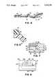
- FIG. 5is an enlarged, fragmentary sectional view taken along the plane V--V of FIG. 2;
- FIG. 6is a fragmentary, side elevation view taken of a mold suitable for forming the hanger, illustrating in phantom a portion of the mold cavity;
- FIG. 7is a fragmentary, sectional view of the resin injection gate for one of the pads molded with the hanger body.
- FIG. 1conventional clamping hanger of the type disclosed in U.S. Pat. No. 3,767,092, noted above, is illustrated.
- This hangerhas an elongated beam-like body 11 supported at the center by an integral hook 12.
- the hangerhas a garment clamp 13 formed by a pair of jaws 14 and 15 integrally joined by a thin section forming a hinge 16 about which the front jaw 14 can be pivoted.
- the rear jaw 15is an integral extension of the hanger body 11 and with respect to the hanger body is stationary.
- the front jaw 14is pivotable about the hinge 16.
- the jawsare resiliently urged into garment clamping position by a U-shaped spring latch 17 which is slidably mounted in a recessed channel.
- each jaw of each clampis provided with a garment gripping pad 20.
- the pads 20are provided adjacent the free end of each jaw and each pad extends substantially the full width of the jaw and approximately a third of its length or vertical height. The distance it extends up the length of the jaw is determined by a number of factors of which the shape of the jaw is an important one.
- the vertical length of the padneed not be more than that which will firmly engage and retain the garment under normal clamping pressure.
- the surface of the padmust project above the edges of the jaw both to assure a positive grip of the garment and to avoid creasing or otherwise marking the garment.
- the functional characteristics of the pads 20are very important.
- the garment engaging surfacesmust have a very high coefficient of friction when firmly pressed against the fabric.
- the actual clamping pressuremust be limited to avoid marking the garment. Further, this must be true for a wide range of fabrics, from cotton and wool to fabrics partially or totally of synthetic materials which have a very smooth or slick type of surface. It must also be able to grip these surfaces without either marking or adhering to the fabric other than solely by reason of friction. Because these hangers must be capable of use as shipping hangers, the material of the pads must be capable of maintaining its geometric integrity, a necessity for maintenance of its gripping ability, and must do so without thermally induced rigidity or softening, such as would materially adversely affect its ability to grip a garment.
- the resilient garment gripping padshave had an unacceptably short life.
- the padsWhen the more compressible materials, such as sponge rubber, have been used, the pads rapidly become distorted and tear. Further, they lack the strength to withstand the weight of the heavier garments. It is also necessary that the pads be able to withstand the abrasion of certain fabrics. It is essential that the pads not mark the fabric, as a number of the materials used in certain rubbers to give them desired characteristics, such as wear resistance and strength, are known to do.
- a further serious problemhas been that of so bonding the pads to the hanger body that they will not delaminate or otherwise become detached from the hanger body even under severe operating conditions.
- the pads of this inventioninstead of being a subsequently attached component of the hanger, are molded substantially simultaneously with the hanger so as to become an integral part of the hanger.
- a two-piece mold 24, fragmentarily illustrated in FIG. 6,is provided having a cavity which simultaneously forms the entire hanger body including both clamps 13. If the hanger is designed with an integral hook, it also is formed by the mold. If a metal hook is used, it is assembled to the hanger body in a subsequent operation.
- the front and rear jaws 14 and 15are molded in the fully open position as illustrated in FIGS. 2, 3 and 4.
- each cavity 25 in which a pad 20 is to be formedis occupied by a cam 26 (FIG. 6).
- cam 26FIG. 6
- the hanger forming resinsuch as polypropylene
- the resinhas set sufficiently that the cams occupying the pad forming cavities are withdrawn, that is, upwardly into the space 26a, as illustrated in FIG. 6.
- the resin to form the padsis injected into the space or pad cavities through the opening 27 which had been sealed by the presence of the cam 26.
- cams 26are moved is not relevant to this invention because equipment for accomplishing this is conventional. For example, it can be effected by timer controlled air cylinders or solenoids. Thereafter, the mold is held closed until both of the injected resins have set sufficiently that the molded hanger, with the pads, can be removed without distortion or loss of geometric integrity.
- a suitable material for molding the padsincludes certain thermoplastic rubbers, such as Kraton G-2706, manufactured by Shell Oil Company.
- the thermoplastic rubber Kraton G-7705has also been found to provide both the desired surface characteristics and to effect an interlocking bond with the polypropylene. It is believed that the bond between the plastic of the hanger body and that of the pad may be formed by a molecularly interlocking polymer network. Whether or not this is correct, it is essential that the bond be substantially better than that normally formed between two quite different thermoplastic resins even when co-molded and different from that provided by known adhesives for joining such resins.
- Both of the above polymershave a Shore hardness of about 28 which provides the pads with excellent fabric gripping characteristics and, at the same time, durability under conditions of repeated use with loads imposed parallel the pad surface.
- the anchor between the pad and the hanger bodybe strong and dependable. It is for this reason that the pads 20 are molded with the hanger body rather than molded separately and subsequently bonded to the hanger body. However, to avoid mixing of the resins, it is necessary that the molding of the hanger body and of the pads be sequential rather than simultaneous, yet remain sequential phases of a single molding cycle.
- this injection of the Kraton materialhas to be executed at a higher temperature than that necessary for the resin of the hanger body and, thus, at the boundary line between the two resins there can be and is some remelting of the resin from which the hanger body has been formed.
- this creep or migration of the pad resinoccurred between the hanger body and the mold.
- the pad resinwas able to force its way into the interior of the already molded shapes because the retained heat made these interior portions softer and more subject to remelting or deformation by the hot incoming material.
- dam 40extending transversely of each of the jaws.
- the dams 40are wedge-shaped. This provides a meeting point between the mold halves which proved to provide a positive cutoff against resin migration.
- the design of the damis important to its ability to provide a solution to the migration problem.
- the damis designed to be relatively thin in cross section. Therefore, it will set or solidify relatively quickly and, as a result, will become more resistant to migration of the pad resin at an earlier stage in the molding cycle. This is very important to avoiding the necessity for lengthening the molding cycle.
- the shape of the damis such that its wall thickness decreases as it extends into the area in which the pad forming material is injected.
- the decreasing wall thicknessfacilitates thermal transfer and, thus, cooling in the areas most subject to heating from the pad forming resin. Where it has the greatest cross-sectional thickness, it is closest to the already cooled portion of both the mold and the previously injected resin.
- its designprovides it with the ability to resist migration of the pad forming resin.
- itsince it creates a thermally stable barrier at what previously was a possible space or area of weakness between the molded hanger body and the mold into which the pad material could migrate under high pressure, it effectively conquered the problem of secondary resin migration. It also proved to be effective against resin migration internally of the adjacent portions of the hanger body. This type of migration was not as aesthetically serious when opaque resins were used for the hanger body but it was totally unacceptable when the hanger body was molded of clear or translucent resins.
- FIG. 7The construction of one of the injection gates for the pad forming resin is illustrated in FIG. 7.
- a separate gateis provided for each pad.
- the mold half 30 forming the exterior surface of a clampseats against the mold half 31 forming the clamp's inner surface along the parting line 42.
- the parting line 42has a portion 42a which follows this exterior face.
- the mold half 30contains cavity 43 in which the clamp is molded.
- the cavity for forming the pad 20is recessed into the mold half 31.
- the conduit 44 for the resin from which the pad is moldedhas a nozzle 45 which intersects the pad cavity 46 to provide a very small opening 27 (see also FIG. 6) into the pad forming cavity which is adjacent the face of the pad remote from the cavity forming the clamp.
- a wedge-shaped shear member 47is provided between the parting line and the opening into the mold cavity.
- the inventionhas been illustrated as practiced with molds that part vertically with the hanger body formed in the lower half of the mold. It will be recognized that the mold halves could be inverted or the parting line of the molds could be arranged vertically without affecting the invention in any way.
- the inventionprovides the first molded plastic garment clamping hanger having high friction garment gripping surfaces molded integrally with the hanger body to provide a hanger usable under the demanding requirements of manufacturing and commercial establishments.
Landscapes
- Engineering & Computer Science (AREA)
- Manufacturing & Machinery (AREA)
- Mechanical Engineering (AREA)
- Holders For Apparel And Elements Relating To Apparel (AREA)
- Injection Moulding Of Plastics Or The Like (AREA)
- Moulds For Moulding Plastics Or The Like (AREA)
Abstract
Description
Claims (9)
Priority Applications (9)
| Application Number | Priority Date | Filing Date | Title |
|---|---|---|---|
| US07/389,947US5020705A (en) | 1989-08-07 | 1989-08-07 | Article gripping means and method of making same |
| CA002006441ACA2006441C (en) | 1989-08-07 | 1989-12-21 | Molded plastic clamping garment hanger with improved garment contacting pads |
| AU52165/90AAU628499B2 (en) | 1989-08-07 | 1990-03-23 | Article gripping means and method of making same |
| JP2135180AJPH0370516A (en) | 1989-08-07 | 1990-05-24 | Article-holding means and making thereof |
| DE69022920TDE69022920T2 (en) | 1989-08-07 | 1990-07-19 | Gripping means for articles and processes for their manufacture. |
| EP90307880AEP0412670B1 (en) | 1989-08-07 | 1990-07-19 | Article gripping means and method of making same |
| US08/072,358US5516014A (en) | 1989-08-07 | 1993-06-03 | Article gripping means and method of making same |
| JP009940UJPH0720944U (en) | 1989-08-07 | 1994-07-08 | Molded plastic clothing holding hanger and manufacturing method thereof |
| HK98107117.6AHK1007946B (en) | 1989-08-07 | 1998-06-27 | Article gripping means and method of making same |
Applications Claiming Priority (1)
| Application Number | Priority Date | Filing Date | Title |
|---|---|---|---|
| US07/389,947US5020705A (en) | 1989-08-07 | 1989-08-07 | Article gripping means and method of making same |
Related Child Applications (1)
| Application Number | Title | Priority Date | Filing Date |
|---|---|---|---|
| US67943691ADivision | 1989-08-07 | 1991-04-02 |
Publications (1)
| Publication Number | Publication Date |
|---|---|
| US5020705Atrue US5020705A (en) | 1991-06-04 |
Family
ID=23540430
Family Applications (2)
| Application Number | Title | Priority Date | Filing Date |
|---|---|---|---|
| US07/389,947Expired - LifetimeUS5020705A (en) | 1989-08-07 | 1989-08-07 | Article gripping means and method of making same |
| US08/072,358Expired - LifetimeUS5516014A (en) | 1989-08-07 | 1993-06-03 | Article gripping means and method of making same |
Family Applications After (1)
| Application Number | Title | Priority Date | Filing Date |
|---|---|---|---|
| US08/072,358Expired - LifetimeUS5516014A (en) | 1989-08-07 | 1993-06-03 | Article gripping means and method of making same |
Country Status (6)
| Country | Link |
|---|---|
| US (2) | US5020705A (en) |
| EP (1) | EP0412670B1 (en) |
| JP (2) | JPH0370516A (en) |
| AU (1) | AU628499B2 (en) |
| CA (1) | CA2006441C (en) |
| DE (1) | DE69022920T2 (en) |
Cited By (28)
| Publication number | Priority date | Publication date | Assignee | Title |
|---|---|---|---|---|
| US5183191A (en)* | 1992-02-06 | 1993-02-02 | Batts, Inc. | Hangers with long lasting non-slip surfaces |
| USD337893S (en) | 1991-07-16 | 1993-08-03 | A & E Products Group, A Division Of Carlisle Plastics, Inc. | Garment hanger body |
| US5297706A (en)* | 1992-12-14 | 1994-03-29 | Mode Plastics, Inc. | Clothes hanger construction with attached locking device |
| US5302440A (en)* | 1990-06-04 | 1994-04-12 | Elbert Davis | Polymer coated contact surface |
| US5361948A (en)* | 1992-01-28 | 1994-11-08 | Batts, Inc. | Inside waistband garment hanger |
| USD352834S (en) | 1993-05-21 | 1994-11-29 | A & E Products Group, A Division Of Carlisle Plastics, Inc. | Garment hanger body |
| US5535927A (en)* | 1991-12-11 | 1996-07-16 | Batts, Inc. | Non-slip hanger and method of manufacture thereof |
| US5785216A (en)* | 1991-05-29 | 1998-07-28 | Spotless Plastics Pty. Ltd. | Method of molding hangers and apparatus for implementing method |
| US5839629A (en)* | 1997-06-09 | 1998-11-24 | Carlisle Plastics, Inc. | Color-coded hanger assembly and apparatus for making same |
| US5890634A (en)* | 1997-12-18 | 1999-04-06 | Carlisle Plastics, Inc. | Hanger with snap-on non-slip pads |
| US6070772A (en)* | 1998-05-11 | 2000-06-06 | Red Wing Products | Non-slip garment hanger with a coordinate loop |
| US6199728B1 (en) | 1997-02-10 | 2001-03-13 | The Accessory Corporation | Garment hanger with integral crease-free clamps |
| US6305586B1 (en)* | 2001-01-16 | 2001-10-23 | Randy Hangers | Hanger clip grip pad |
| US6306329B1 (en) | 1998-08-11 | 2001-10-23 | Randy Hangers | Method of molding garment hanger clip |
| US20030183665A1 (en)* | 2002-03-28 | 2003-10-02 | Spotless Plastics Pty. Ltd. | Method for anchoring an elastomer into a thermoplastic during injection molding |
| US20050139625A1 (en)* | 2003-11-12 | 2005-06-30 | Spotless Plastics Pty, Ltd. | Knitwear hanger |
| US20050184109A1 (en)* | 2003-11-14 | 2005-08-25 | Goldman Allan J. | Garment hanger with non-slip pads |
| US20050244213A1 (en)* | 2001-09-28 | 2005-11-03 | Carmen Maria D | Ergonomic binder clip and method for binding sheets of paper |
| US20050257353A1 (en)* | 2002-09-11 | 2005-11-24 | Peter Rohrig | Clip for a dummy strap |
| US20060163294A1 (en)* | 2005-01-25 | 2006-07-27 | Steven Sutton | Garment hangers with improved gripping pads and improved methods of manufacture |
| USD527194S1 (en) | 2005-10-21 | 2006-08-29 | Wai Shing Yau | Information tab mount for garment hanger |
| USD530526S1 (en) | 2006-01-18 | 2006-10-24 | Wai Shing Yau | Accessory hanger |
| USD531824S1 (en) | 2005-09-21 | 2006-11-14 | Wai Shing Yau | Garment hanger with dependent loop |
| US7299957B1 (en) | 2004-08-25 | 2007-11-27 | The Accessory Corp. | Clamp-type article hanger |
| USD570614S1 (en) | 2006-02-17 | 2008-06-10 | Wai Shing Yau | Pinch clip grip |
| US7537142B2 (en) | 2006-04-12 | 2009-05-26 | Wai Shing Plastic Products Ltd. | Pinch clip garment hanger with modular friction pads |
| US7628302B2 (en) | 2006-01-12 | 2009-12-08 | Wai Shing Yau | Garment hanger with dependent loop and accessory hanger |
| US10342393B1 (en) | 2016-07-14 | 2019-07-09 | Solazo, Ltd | Towel holding device and towel holding system that includes the towel holding device |
Families Citing this family (27)
| Publication number | Priority date | Publication date | Assignee | Title |
|---|---|---|---|---|
| GB2242122A (en)* | 1990-03-19 | 1991-09-25 | Morplan | Garment hangers |
| EP0812669B1 (en)* | 1991-05-29 | 2004-07-28 | Spotless Plastics Pty. Ltd. | Method of molding a composite plastic garment hanger |
| US5814252A (en)* | 1991-10-17 | 1998-09-29 | Spotless Plastics Pty. Ltd. | Method of molding coinjected plastic garment hangers |
| GB2297031B (en)* | 1992-02-06 | 1996-09-11 | Batts Inc | Hangers with long lasting non-slip surfaces |
| US5441679A (en)* | 1993-06-03 | 1995-08-15 | Studor, Inc. | Method of assembling a value head |
| US6098254A (en)* | 1998-07-14 | 2000-08-08 | Randy Hangers | Garment hanger clip release guard |
| US6047868A (en)* | 1998-10-29 | 2000-04-11 | Petrou; Nicoleon | Exclusively plastic pinch-grip hanger |
| US6119906A (en)* | 1999-02-25 | 2000-09-19 | Red Wing Products, Inc. | Hanger with integrated clips |
| US6508388B1 (en)* | 1999-05-21 | 2003-01-21 | Henry John Louw | Hanger |
| DE20018494U1 (en)* | 2000-10-28 | 2001-01-18 | Coronet-Kunststoffwerk Gmbh, 64689 Grasellenbach | Hangers |
| US6742228B1 (en)* | 2000-11-17 | 2004-06-01 | Young Chang Kim | Hanger having clamp with pad |
| US6711808B2 (en) | 2002-02-15 | 2004-03-30 | Spotless Plastics Pty. Ltd. | Pinch grip hanger loading mechanism |
| GB2401038B (en)* | 2002-02-15 | 2006-05-17 | Stanley Frederick Gouldson | Improved pinch grip hangers |
| US7121439B2 (en)* | 2002-02-15 | 2006-10-17 | Spotless Plastics Pty. Ltd. | Pinch grip hanger |
| US7156271B2 (en)* | 2002-09-17 | 2007-01-02 | Henry John Louw | Garment hanger end-clip having a stop member and method of manufacture |
| US20040065702A1 (en)* | 2002-10-07 | 2004-04-08 | Kevin Yang | Garment hanger |
| US20040144813A1 (en)* | 2002-11-08 | 2004-07-29 | Louw Henry John | Hanger with soft pad |
| US7104428B2 (en)* | 2003-02-14 | 2006-09-12 | Spotless Plastic Pty. Ltd. | Hanger beam construction |
| GB2413071B (en)* | 2005-03-31 | 2007-01-03 | Nick Lewis | Garment hanger and garment or other clip therefor |
| USD670920S1 (en)* | 2011-07-01 | 2012-11-20 | Mainetti (Uk) Limited | Garment hanger |
| USD681352S1 (en)* | 2012-05-29 | 2013-05-07 | Mainetti (Uk) Limited | Garment hanger |
| USD684383S1 (en)* | 2012-11-28 | 2013-06-18 | Uniplast Industries, Inc. | Garment hanger |
| USD866200S1 (en)* | 2018-08-13 | 2019-11-12 | Target Brands, Inc. | Hanger |
| USD882969S1 (en)* | 2018-09-17 | 2020-05-05 | Target Brands, Inc. | Hanger |
| US11304553B2 (en) | 2018-09-17 | 2022-04-19 | Target Brands, Inc. | Hanger system with hanger coupling member |
| US10722062B1 (en)* | 2019-05-24 | 2020-07-28 | Umf Corporation | Curtain pull |
| CN113858542B (en)* | 2021-10-13 | 2023-06-20 | 苏州优耐鑫模具科技有限公司 | Rotary switching type double-color injection mold |
Citations (7)
| Publication number | Priority date | Publication date | Assignee | Title |
|---|---|---|---|---|
| US1205551A (en)* | 1916-02-19 | 1916-11-21 | David H Leach | Trousers hanger and stretcher. |
| US2212978A (en)* | 1939-01-25 | 1940-08-27 | Mackie Lovejoy Mfg Co | Garment hanger |
| US2463136A (en)* | 1946-12-31 | 1949-03-01 | Sr Walter S Baer | Garment hanger |
| US2535521A (en)* | 1947-02-21 | 1950-12-26 | Alfred C Schoepfer | Garment hanger |
| US2920801A (en)* | 1958-11-10 | 1960-01-12 | Batts John T Inc | Trousers hanger |
| US3102668A (en)* | 1961-04-14 | 1963-09-03 | Harry R Milligan | Clothes hanger |
| US3767092A (en)* | 1972-01-31 | 1973-10-23 | Thomas Batts Inc J | Garment clamping hanger with slidable locking clip |
Family Cites Families (11)
| Publication number | Priority date | Publication date | Assignee | Title |
|---|---|---|---|---|
| US4084299A (en)* | 1976-11-26 | 1978-04-18 | Kohshoh Limited | Plastic clip |
| PL122159B1 (en)* | 1979-09-15 | 1982-06-30 | Inst Elektrotechniki | High tension overhead-line instulator of plastic materialx and method of manufacturing the samerytykh ustanovok i sposob izgotovlenija plastmassovogo izoljatora vysokogo naprjazhenija dlja otkrytykh ustanovok |
| US4385025A (en)* | 1979-10-22 | 1983-05-24 | Barry Wright Corporation | Method of coinjection molding of thermoplastic and thermoplastic elastomer |
| JPS57150263A (en)* | 1981-03-12 | 1982-09-17 | Nec Corp | Continuity test system of digital board trunk |
| JPS5921619A (en)* | 1982-07-28 | 1984-02-03 | Tatsuo Shiyoukaku | Preparation of remedy for athlete's foot |
| FR2542715B1 (en)* | 1983-03-16 | 1987-11-06 | Saphem | COMPACTION DEVICE, ESPECIALLY OF THE CONTENT OF A LARGE CAPACITY SEMI-TRAILER BODY |
| US4512720A (en)* | 1983-04-12 | 1985-04-23 | Barry Wright Corporation | Pump impellers and manufacture thereof by co-injection molding |
| JPS6137121A (en)* | 1984-07-28 | 1986-02-22 | 磯 直行 | Hanger gripper part |
| DE3446020A1 (en)* | 1984-12-17 | 1986-06-19 | Peguform-Werke GmbH, 7805 Bötzingen | Process for producing injection moulded parts from plastic |
| JPH07118178B2 (en)* | 1987-01-28 | 1995-12-18 | 富士写真フイルム株式会社 | Magnetic tape cassette manufacturing method |
| US5022571A (en)* | 1989-12-05 | 1991-06-11 | Batts, Inc. | Internal garment hanger with tensioning springs and straps |
- 1989
- 1989-08-07USUS07/389,947patent/US5020705A/ennot_activeExpired - Lifetime
- 1989-12-21CACA002006441Apatent/CA2006441C/ennot_activeExpired - Lifetime
- 1990
- 1990-03-23AUAU52165/90Apatent/AU628499B2/ennot_activeExpired
- 1990-05-24JPJP2135180Apatent/JPH0370516A/enactivePending
- 1990-07-19DEDE69022920Tpatent/DE69022920T2/ennot_activeExpired - Fee Related
- 1990-07-19EPEP90307880Apatent/EP0412670B1/ennot_activeExpired - Lifetime
- 1993
- 1993-06-03USUS08/072,358patent/US5516014A/ennot_activeExpired - Lifetime
- 1994
- 1994-07-08JPJP009940Upatent/JPH0720944U/enactivePending
Patent Citations (7)
| Publication number | Priority date | Publication date | Assignee | Title |
|---|---|---|---|---|
| US1205551A (en)* | 1916-02-19 | 1916-11-21 | David H Leach | Trousers hanger and stretcher. |
| US2212978A (en)* | 1939-01-25 | 1940-08-27 | Mackie Lovejoy Mfg Co | Garment hanger |
| US2463136A (en)* | 1946-12-31 | 1949-03-01 | Sr Walter S Baer | Garment hanger |
| US2535521A (en)* | 1947-02-21 | 1950-12-26 | Alfred C Schoepfer | Garment hanger |
| US2920801A (en)* | 1958-11-10 | 1960-01-12 | Batts John T Inc | Trousers hanger |
| US3102668A (en)* | 1961-04-14 | 1963-09-03 | Harry R Milligan | Clothes hanger |
| US3767092A (en)* | 1972-01-31 | 1973-10-23 | Thomas Batts Inc J | Garment clamping hanger with slidable locking clip |
Cited By (35)
| Publication number | Priority date | Publication date | Assignee | Title |
|---|---|---|---|---|
| US5302440A (en)* | 1990-06-04 | 1994-04-12 | Elbert Davis | Polymer coated contact surface |
| US6085950A (en)* | 1991-05-29 | 2000-07-11 | Spotless Plastics Pty. Ltd. | Coinjected plastic garment hangers |
| US5785216A (en)* | 1991-05-29 | 1998-07-28 | Spotless Plastics Pty. Ltd. | Method of molding hangers and apparatus for implementing method |
| USD337893S (en) | 1991-07-16 | 1993-08-03 | A & E Products Group, A Division Of Carlisle Plastics, Inc. | Garment hanger body |
| US5535927A (en)* | 1991-12-11 | 1996-07-16 | Batts, Inc. | Non-slip hanger and method of manufacture thereof |
| US5361948A (en)* | 1992-01-28 | 1994-11-08 | Batts, Inc. | Inside waistband garment hanger |
| US5183191A (en)* | 1992-02-06 | 1993-02-02 | Batts, Inc. | Hangers with long lasting non-slip surfaces |
| US5297706A (en)* | 1992-12-14 | 1994-03-29 | Mode Plastics, Inc. | Clothes hanger construction with attached locking device |
| USD352834S (en) | 1993-05-21 | 1994-11-29 | A & E Products Group, A Division Of Carlisle Plastics, Inc. | Garment hanger body |
| US6199728B1 (en) | 1997-02-10 | 2001-03-13 | The Accessory Corporation | Garment hanger with integral crease-free clamps |
| US5839629A (en)* | 1997-06-09 | 1998-11-24 | Carlisle Plastics, Inc. | Color-coded hanger assembly and apparatus for making same |
| US5890634A (en)* | 1997-12-18 | 1999-04-06 | Carlisle Plastics, Inc. | Hanger with snap-on non-slip pads |
| US6070772A (en)* | 1998-05-11 | 2000-06-06 | Red Wing Products | Non-slip garment hanger with a coordinate loop |
| US6306329B1 (en) | 1998-08-11 | 2001-10-23 | Randy Hangers | Method of molding garment hanger clip |
| US6305586B1 (en)* | 2001-01-16 | 2001-10-23 | Randy Hangers | Hanger clip grip pad |
| US20050244213A1 (en)* | 2001-09-28 | 2005-11-03 | Carmen Maria D | Ergonomic binder clip and method for binding sheets of paper |
| US6772923B2 (en)* | 2002-03-28 | 2004-08-10 | Spotless Plastics Pty. Ltd. | Method for anchoring an elastomer into a thermoplastic during injection molding |
| GB2388811B (en)* | 2002-03-28 | 2005-10-05 | Spotless Plastics Pty Ltd | A coinjected plastic garment hanger and a method of coinjecting molding a composite plastic garment hanger |
| US20030183665A1 (en)* | 2002-03-28 | 2003-10-02 | Spotless Plastics Pty. Ltd. | Method for anchoring an elastomer into a thermoplastic during injection molding |
| CN100354101C (en)* | 2002-03-28 | 2007-12-12 | 斯波特雷斯塑料有限公司 | Method for anchoring an elastomer into a thermoplastic during injection molding |
| US20040222254A1 (en)* | 2002-03-28 | 2004-11-11 | Spotless Plastics Pty. Ltd. | Method for anchoring an elastomer into a thermoplastic during injection molding |
| US20050257353A1 (en)* | 2002-09-11 | 2005-11-24 | Peter Rohrig | Clip for a dummy strap |
| US20050139625A1 (en)* | 2003-11-12 | 2005-06-30 | Spotless Plastics Pty, Ltd. | Knitwear hanger |
| US7150381B2 (en) | 2003-11-14 | 2006-12-19 | Uniplast Industries, Inc. | Garment hanger with non-slip pads |
| US20050184109A1 (en)* | 2003-11-14 | 2005-08-25 | Goldman Allan J. | Garment hanger with non-slip pads |
| US7299957B1 (en) | 2004-08-25 | 2007-11-27 | The Accessory Corp. | Clamp-type article hanger |
| US7249698B2 (en) | 2005-01-25 | 2007-07-31 | The Accessory Corp. | Garment hangers with improved gripping pads and improved methods of manufacture |
| US20060163294A1 (en)* | 2005-01-25 | 2006-07-27 | Steven Sutton | Garment hangers with improved gripping pads and improved methods of manufacture |
| USD531824S1 (en) | 2005-09-21 | 2006-11-14 | Wai Shing Yau | Garment hanger with dependent loop |
| USD527194S1 (en) | 2005-10-21 | 2006-08-29 | Wai Shing Yau | Information tab mount for garment hanger |
| US7628302B2 (en) | 2006-01-12 | 2009-12-08 | Wai Shing Yau | Garment hanger with dependent loop and accessory hanger |
| USD530526S1 (en) | 2006-01-18 | 2006-10-24 | Wai Shing Yau | Accessory hanger |
| USD570614S1 (en) | 2006-02-17 | 2008-06-10 | Wai Shing Yau | Pinch clip grip |
| US7537142B2 (en) | 2006-04-12 | 2009-05-26 | Wai Shing Plastic Products Ltd. | Pinch clip garment hanger with modular friction pads |
| US10342393B1 (en) | 2016-07-14 | 2019-07-09 | Solazo, Ltd | Towel holding device and towel holding system that includes the towel holding device |
Also Published As
| Publication number | Publication date |
|---|---|
| JPH0720944U (en) | 1995-04-18 |
| DE69022920D1 (en) | 1995-11-16 |
| EP0412670A3 (en) | 1991-08-07 |
| CA2006441A1 (en) | 1991-02-07 |
| HK1007946A1 (en) | 1999-04-30 |
| EP0412670A2 (en) | 1991-02-13 |
| EP0412670B1 (en) | 1995-10-11 |
| CA2006441C (en) | 1995-03-14 |
| AU5216590A (en) | 1991-02-07 |
| AU628499B2 (en) | 1992-09-17 |
| US5516014A (en) | 1996-05-14 |
| DE69022920T2 (en) | 1996-04-25 |
| JPH0370516A (en) | 1991-03-26 |
Similar Documents
| Publication | Publication Date | Title |
|---|---|---|
| US5020705A (en) | Article gripping means and method of making same | |
| US6772923B2 (en) | Method for anchoring an elastomer into a thermoplastic during injection molding | |
| US6085950A (en) | Coinjected plastic garment hangers | |
| EP1530936B1 (en) | Knitwear hanger | |
| AU781626B2 (en) | Coordinate loop garment hanger | |
| US5814252A (en) | Method of molding coinjected plastic garment hangers | |
| KR860002128B1 (en) | Swivel snap hook of synthetic resin and method of manufacturing the same | |
| EP0282987B1 (en) | Method of making injection-molded slide fastener sliders | |
| CN101356063A (en) | Molded binder | |
| AU598713B2 (en) | Slider for slide fasteners | |
| IE860081L (en) | Applying seals to plastic pipe ends. | |
| US7134192B1 (en) | Closure device | |
| US8281965B2 (en) | Garment hanger with top sizer | |
| US6883210B1 (en) | Closure device | |
| CA2070037C (en) | Coinjected plastic garment hangers, method of molding hangers and apparatus for implementing method | |
| HK1007946B (en) | Article gripping means and method of making same | |
| HK1004599B (en) | Coinjected plastic garment hanger | |
| US20030178744A1 (en) | Multicolour and multiple material injection moulding of a capsule provided with a cap pivoting about a hinge | |
| WO1990000023A1 (en) | Clothes hanger | |
| HK1062422A (en) | Method for anchoring an elastomer into a thermoplastic during injection molding | |
| HK1004668B (en) | Method of molding a composite plastic garment hanger | |
| JPS59186506A (en) | Compact container manufacturing method |
Legal Events
| Date | Code | Title | Description |
|---|---|---|---|
| AS | Assignment | Owner name:BATTS, INC., 200 N. FRANKLIN, ZEELAND, MI 49464 A Free format text:ASSIGNMENT OF ASSIGNORS INTEREST.;ASSIGNOR:GARRISON, JUDD;REEL/FRAME:005111/0323 Effective date:19890721 | |
| STCF | Information on status: patent grant | Free format text:PATENTED CASE | |
| CC | Certificate of correction | ||
| FEPP | Fee payment procedure | Free format text:PAYOR NUMBER ASSIGNED (ORIGINAL EVENT CODE: ASPN); ENTITY STATUS OF PATENT OWNER: LARGE ENTITY | |
| FPAY | Fee payment | Year of fee payment:4 | |
| FEPP | Fee payment procedure | Free format text:PAYER NUMBER DE-ASSIGNED (ORIGINAL EVENT CODE: RMPN); ENTITY STATUS OF PATENT OWNER: LARGE ENTITY Free format text:PAYOR NUMBER ASSIGNED (ORIGINAL EVENT CODE: ASPN); ENTITY STATUS OF PATENT OWNER: LARGE ENTITY | |
| FPAY | Fee payment | Year of fee payment:8 | |
| FPAY | Fee payment | Year of fee payment:12 | |
| AS | Assignment | Owner name:TYCO PLASTIC SERVICES AG, SWITZERLAND Free format text:ASSIGNMENT OF ASSIGNORS INTEREST;ASSIGNOR:BATTS, INC.;REEL/FRAME:013542/0036 Effective date:20021120 | |
| AS | Assignment | Owner name:TYCO PLASTICS SERVICES AG, SWITZERLAND Free format text:CORRECTIVE ASSIGNMENT TO CORRECT ASSIGNMENT DOCUMENT PREVIOUSLY RECORDED AT REEL 013542 FRAME 0036;ASSIGNOR:BATTS, INC.;REEL/FRAME:015293/0941 Effective date:20040421 | |
| AS | Assignment | Owner name:GHA BRANDS LTD, MALAYSIA Free format text:ASSIGNMENT OF ASSIGNORS INTEREST;ASSIGNOR:TYCO PLASTICS SERVICES AG;REEL/FRAME:018627/0297 Effective date:20060629 |