US5020470A - Wet scrubber apparatus and paint spraybooth in combination with wet scrubber apparatus - Google Patents
Wet scrubber apparatus and paint spraybooth in combination with wet scrubber apparatusDownload PDFInfo
- Publication number
- US5020470A US5020470AUS07/402,217US40221789AUS5020470AUS 5020470 AUS5020470 AUS 5020470AUS 40221789 AUS40221789 AUS 40221789AUS 5020470 AUS5020470 AUS 5020470A
- Authority
- US
- United States
- Prior art keywords
- discharge
- sidewalls
- chamber
- receptacle
- paint
- Prior art date
- Legal status (The legal status is an assumption and is not a legal conclusion. Google has not performed a legal analysis and makes no representation as to the accuracy of the status listed.)
- Expired - Lifetime
Links
- 239000003973paintSubstances0.000titleclaimsdescription61
- XLYOFNOQVPJJNP-UHFFFAOYSA-NwaterSubstancesOXLYOFNOQVPJJNP-UHFFFAOYSA-N0.000claimsabstractdescription43
- 238000005192partitionMethods0.000claimsabstractdescription22
- 239000007788liquidSubstances0.000claimsabstractdescription6
- 239000012530fluidSubstances0.000claims4
- 238000005201scrubbingMethods0.000description10
- 238000005200wet scrubbingMethods0.000description5
- 238000000889atomisationMethods0.000description4
- 230000008901benefitEffects0.000description2
- 230000008859changeEffects0.000description2
- 239000006185dispersionSubstances0.000description2
- 239000006260foamSubstances0.000description2
- 239000000463materialSubstances0.000description2
- 238000012986modificationMethods0.000description2
- 230000004048modificationEffects0.000description2
- 125000006850spacer groupChemical group0.000description2
- 230000000694effectsEffects0.000description1
- 230000008030eliminationEffects0.000description1
- 238000003379elimination reactionMethods0.000description1
- 230000007613environmental effectEffects0.000description1
- 230000036541healthEffects0.000description1
- 230000003116impacting effectEffects0.000description1
- 238000012423maintenanceMethods0.000description1
- 239000002184metalSubstances0.000description1
- 238000000034methodMethods0.000description1
- 230000009972noncorrosive effectEffects0.000description1
- 238000007591painting processMethods0.000description1
- 239000007787solidSubstances0.000description1
- 239000007921spraySubstances0.000description1
- 238000005507sprayingMethods0.000description1
- 229910001220stainless steelInorganic materials0.000description1
- 239000010935stainless steelSubstances0.000description1
- 230000003068static effectEffects0.000description1
- 238000009692water atomizationMethods0.000description1
Images


Classifications
- B—PERFORMING OPERATIONS; TRANSPORTING
- B05—SPRAYING OR ATOMISING IN GENERAL; APPLYING FLUENT MATERIALS TO SURFACES, IN GENERAL
- B05B—SPRAYING APPARATUS; ATOMISING APPARATUS; NOZZLES
- B05B14/00—Arrangements for collecting, re-using or eliminating excess spraying material
- B05B14/40—Arrangements for collecting, re-using or eliminating excess spraying material for use in spray booths
- B05B14/46—Arrangements for collecting, re-using or eliminating excess spraying material for use in spray booths by washing the air charged with excess material
- B05B14/468—Arrangements for collecting, re-using or eliminating excess spraying material for use in spray booths by washing the air charged with excess material with scrubbing means arranged below the booth floor
- Y—GENERAL TAGGING OF NEW TECHNOLOGICAL DEVELOPMENTS; GENERAL TAGGING OF CROSS-SECTIONAL TECHNOLOGIES SPANNING OVER SEVERAL SECTIONS OF THE IPC; TECHNICAL SUBJECTS COVERED BY FORMER USPC CROSS-REFERENCE ART COLLECTIONS [XRACs] AND DIGESTS
- Y10—TECHNICAL SUBJECTS COVERED BY FORMER USPC
- Y10S—TECHNICAL SUBJECTS COVERED BY FORMER USPC CROSS-REFERENCE ART COLLECTIONS [XRACs] AND DIGESTS
- Y10S55/00—Gas separation
- Y10S55/46—Spray booths
Definitions
- the present inventionsrelates generally to apparatus for use in removing solid or liquid particulates from an air stream. More particularly, the present invention relates to a paint spraybooth facility having a wet scrubbing apparatus to remove paint particulate from the air exhaust stream exiting the spraybooth.
- paint particulatemay be effectively removed from the spraybooth facility air exhaust through the use of wet scrubbing apparatus.
- wet scrubbing systemstypically draw air from the paint application chamber into water flooded continuous slots or discrete discharge tubes disposed in the floor of the paint application chamber.
- the wateris at least partially disbursed or atomized within the slots or discharge tubes and thereby intimately mixed with the paint-laden air to remove or scrub the paint particulate from the air.
- the present inventionis directed to a wet scrubbing apparatus for use in combination with a work station in which airborne particulates are generated and in which a need exists for removal of the particulates from the air exiting the work station. More particularly, the invention is directed to a paint spraybooth facility utilizing a wet scrubber apparatus to remove paint particulate from the air stream exiting the paint application chamber of the spraybooth facility.
- the apparatus of the present inventionovercomes disadvantages associated with the prior art by substantially reducing the sound power level and, therefore, the noise generated by the wet scrubber apparatus while increasing the scrubbing efficiency of the system.
- a wet scrubberfor use in combination with a work station in which airborne particulates are generated.
- the wet scrubberincludes a generally horizontal partition which defines a lower boundary of the work station and a discharge structure depending from the partition. Means are provided for supplying a flow of liquid into the discharge structure and for supplying a flow of air carrying the particulate from the work station into and through the discharge structure.
- a scrubber chamberis also provided into which the discharge structure projects, the chamber including a receptacle for containing a pool of liquid.
- the discharge structureitself is constructed to include an elongated inlet channel and a plurality of discrete discharge tubes extending down into the scrubber chamber.
- the inlet channelis formed by a pair of converging sidewalls which depend from the partition at the top of the channel.
- Each of the discharge tubeshas sidewalls and endwalls extending down from the bottom of the channel and together forming a discharge port which is directed at the receptacle within the scrubber chamber.
- the discharge structureis configured and constructed to eliminate or minimize the atomization or dispersion of water flowing through it.
- the converging inlet channelhas a shape which minimizes water dispersion.
- the sidewalls of the inlet channelare generally unobstructed, and the sidewalls of each discharge tube join or merge with the sidewalls of the inlet channel to form a generally unobstructed surface, permitting unimpeded flow of the water from the application chamber through the discharge structure and into the receptacle of the scrubber chamber.
- the plurality of discrete discharge tubesare separated by spacing elements which span the opening between the inlet channel sidewalls, with each of the spacing elements being formed in such a manner as to direct a portion of the water flowing into the inlet channel onto the endwalls of the adjacent discharge tubes.
- Another object of the present inventionis to provide a wet scrubber apparatus for use in combination with a paint spraybooth facility which is designed to substantially reduce the sound power level generated by the scrubber apparatus and the noise perceptible within the paint application chamber of the spraybooth facility.
- Still another object of the present inventionis to provide a wet scrubber apparatus for use in combination with a paint spraybooth facility which requires less static pressure, and thereby less energy, to achieve a given level of paint removal capacity from the air effluent of the paint spraybooth facility.
- a still further object of the present inventionis to provide a scrubber apparatus for use in combination with a paint spraybooth facility which requires less water consumption to achieve a given level of paint removal from the air exhaust of the paint spraybooth facility.
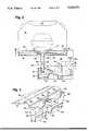
- FIG. 1is a perspective and cross-sectional view illustrating a paint spraybooth facility and a wet scrubber apparatus constructed in accordance with the present invention
- FIG. 2is a transverse cross-sectional view of the paint spraybooth of FIG. 1 showing a conveyor and an automobile (in phantom) passing through the spraybooth facility;
- FIG. 3is a partial plan view taken along line 3--3 of FIG. 2;
- FIG. 4is a transverse cross-sectional view similar to that of FIG. 2 but showing an alternative embodiment of the scrubbing apparatus of the present invention.
- FIG. 5is a partial perspective view showing in greater detail the components of the discharge structure employed in the wet scrubber apparatus of the present invention.
- a paint spraybooth facilitydesignated generally as 10, is illustrated and includes an elongated housing or paint application chamber 12 through which automobiles or other articles to be painted are conveyed. It is within application chamber 12 that the paint spray equipment is housed and in which the operators of such equipment are typically located during the painting process. Above the main working area is a supply plenum 14 which introduces fresh air into the paint application chamber 12.
- the chamber 12also includes a working floor, conventionally constructed as an open metal grid 16. Positioned below the working floor 16 is a generally horizontal partition 18 which defines the bottom of the paint application chamber and the top of the scrubber chamber 20.
- the scrubber chamberalso includes a centrally disposed and longitudinally extending trough or receptacle 24, a longitudinally extending sluice 26, a vertically upstanding air flow diverter 27 and a plurality of baffles 28.
- the air exiting scrubber chamber 20is discharged to the ambient environment via discharge plenum or duct work 30.
- wateris supplied by any one of a number of well known conventional means 33 to the bottom of the application chamber 12 so that the water flows across partition 18 and into and through discharge structure 22.
- the wateraccumulates in trough 24 forming a water impact pool 32 whose function and operation will be described more fully below.
- the overflow from pool 32traverses a spillway 34 into sluice 26.
- the air introduced into application chamber 12 via plenum 14passes around the article to be sprayed, thereby entraining the paint particulate overspray, and passes down and through discharge structure 22 into scrubber chamber 20.
- the paint particulate carried in the airstreamis removed as the air makes it circuitous path through the scrubber apparatus.
- water which initially intermixes with the air in the scrubber apparatusis also removed so that a substantially dry and paint free effluent is discharged from the air exhaust duct work 30 into the ambient environment.
- the discharge structure 22is provided with an elongated substantially continuous inlet channel 40, having a top 42 and a bottom 44.
- This continuous inlet channelis defined by a pair of converging sidewalls 46 which depend, or hang down from, the horizontal partition 18.
- Sidewalls 46are most preferably of a curved configuration, as illustrated; but other more economically fabricated configurations, such as a V-shape or a series of flat segments equivalent to a curved surface, may also be used.
- the discharge structure 22also includes, in accordance with the present invention, a plurality of discrete discharge tubes 50 each having a pair of sidewalls 52 and a pair of endwalls 56 which together form discharge ports, designated as 60, directed toward the receptacle 24 in scrubber chamber 20.
- the bottom of each inlet channel sidewall 46merges or joins with the top of each discharge tube sidewall 52 thereby forming a generally unobstructed surface which permits the unimpeded flow of water cascading downward from the application chamber 12 into the receptacle 24 of the scrubber chamber 20.
- the discharge structure 22is preferably positioned along the longitudinal center line of the application chamber 12 and directly below the shroud 15 which surrounds the bottom of the spraybooth conveyor system.
- the discharge tubes 50have a lateral dimension less than the lateral dimension of the shroud, preferably a dimension no more than one-half the dimension of the shroud. For example, for a shroud having a lateral dimension of approximately 24-30 inches, a preferred lateral dimension for the discharge tubes is approximately 10 inches. This relationship serves to attenuate noise that would otherwise propagate into the application chamber 12.
- the discrete discharge tubes 50are each separated along the longitudinal length of the inlet chamber 40 by spacer elements 62 which, most preferably, include a centrally recessed area 64.
- spacer elements 62which, most preferably, include a centrally recessed area 64.
- paint spraybooth facilities constructed in accordance with the present inventionexhibit sound levels of approximately 75-79 dBA, whereas comparable prior art systems exhibit sound levels in excess of 80 dBA and commonly in excess of 85 dBA. Because sound levels are measured on a logarithmic decibel scale, a change of about 3 decibels represents about a doubling of the sound level. Thus, a change from 75 to 85 dBA results in a sound level approximately 8 times louder to the human ear.
- the present inventiontherefore, provides an important occupational health and safety advantage over prior art systems.
- the apparatus of the present inventionis less sensitive to changes in water flow within tubes 50 or fouling than are prior art devices. As a result, changes in water flow and some fouling of the inlet chamber 40 and discharge tubes 50 does not require maintenance to the extent necessary with prior art systems.
- the apparatus of the present inventionuses less water than some prior art systems. Preferably, the water volume necessary to achieve the desired efficiency is about 30 gallons per minute per linear foot of paint spraybooth length.
- the longitudinally extending impact pool 32may be generally centrally disposed within scrubbing chamber 20 so that the air exiting the impact pool 32 will move transversely toward one side of the chamber 20 and ultimately into exit ductwork 30.
- the airmust travel a circuitous path from pool 32 until it reaches duct 30 and, for this purpose, a plurality of vertically upstanding baffles 28 may be employed.
- the sluice 26be positioned between the receptacle 24 and the discharge ductwork and adjacent or proximate to the impact pool 32.
- a vertically upstanding baffle 27is positioned at or near the downstream side of sluice 26, while a generally horizontally extending baffle 31 is positioned above pool 32 and over spillway 34.
- air exiting discharge ports 60will impact the pool 32, then travel beneath horizontal baffle 31 and up and over vertically upstanding baffle 27 on its way to the discharge duct 30.
- the location of sluice 26 relatively proximate to the impact pool 32 together with the described location and orientation of baffles 29 and 31result in the substantial dewatering of the airstream as it passes from the impact pool 32 and is discharged from the scrubber chamber 20.
- any foam that has been created in the scrubbing apparatuswill be trapped by baffle 27 and water dropping from the airstream at this location will tend to reduce or minimize the amount of foam present within the scrubber chamber 20.
- the lateral vertical wall 66 of trough 24may be made coincident with the sidewalls 52 of the discharge tubes 50.
- This designsubstantially reduces the interior surface of the scrubber chamber 20 which is exposed to the water and airstream exhaust coming from application chamber 12. Because these surfaces must often be plated with or constructed from a non-corrosive material, such as stainless steel, the alternative design depicted in FIG. 4 can substantially reduce the cost of the scrubbing apparatus in general. In addition, the unused space immediately adjacent to the scrubber may then be advantageously employed for locating other equipment necessary to the paint finishing operation.
Landscapes
- Details Or Accessories Of Spraying Plant Or Apparatus (AREA)
- Separation Of Particles Using Liquids (AREA)
- Nozzles (AREA)
Abstract
Description
Claims (12)
Priority Applications (6)
| Application Number | Priority Date | Filing Date | Title |
|---|---|---|---|
| US07/402,217US5020470A (en) | 1989-08-31 | 1989-08-31 | Wet scrubber apparatus and paint spraybooth in combination with wet scrubber apparatus |
| ES90301454TES2063915T3 (en) | 1989-08-31 | 1990-02-12 | AIR CLEANING DEVICE. |
| EP90301454AEP0415511B1 (en) | 1989-08-31 | 1990-02-12 | Air cleaning apparatus |
| DE69011599TDE69011599T2 (en) | 1989-08-31 | 1990-02-12 | Air purification device. |
| JP2148440AJPH08217B2 (en) | 1989-08-31 | 1990-06-06 | Air cleaning device |
| CA002021060ACA2021060A1 (en) | 1989-08-31 | 1990-07-12 | Wet scrubber apparatus and paint spraybooth in combination with wet scrubber apparatus |
Applications Claiming Priority (1)
| Application Number | Priority Date | Filing Date | Title |
|---|---|---|---|
| US07/402,217US5020470A (en) | 1989-08-31 | 1989-08-31 | Wet scrubber apparatus and paint spraybooth in combination with wet scrubber apparatus |
Publications (1)
| Publication Number | Publication Date |
|---|---|
| US5020470Atrue US5020470A (en) | 1991-06-04 |
Family
ID=23591018
Family Applications (1)
| Application Number | Title | Priority Date | Filing Date |
|---|---|---|---|
| US07/402,217Expired - LifetimeUS5020470A (en) | 1989-08-31 | 1989-08-31 | Wet scrubber apparatus and paint spraybooth in combination with wet scrubber apparatus |
Country Status (6)
| Country | Link |
|---|---|
| US (1) | US5020470A (en) |
| EP (1) | EP0415511B1 (en) |
| JP (1) | JPH08217B2 (en) |
| CA (1) | CA2021060A1 (en) |
| DE (1) | DE69011599T2 (en) |
| ES (1) | ES2063915T3 (en) |
Cited By (17)
| Publication number | Priority date | Publication date | Assignee | Title |
|---|---|---|---|---|
| US5100442A (en)* | 1991-04-29 | 1992-03-31 | Durr Industries, Inc. | Gas scrubber system |
| US5147422A (en)* | 1991-08-05 | 1992-09-15 | George Koch Sons, Inc. | Paint spray booth |
| US5302071A (en)* | 1991-08-28 | 1994-04-12 | Svedala Industries, Inc. | Dust containment system for bottom dumping railroad cars |
| US5360539A (en)* | 1992-07-27 | 1994-11-01 | Abb Flakt Aktiebolag | Scrubbing water handling system for paint spray booths |
| US5425802A (en)* | 1993-05-05 | 1995-06-20 | The United States Of American As Represented By The Administrator Of Environmental Protection Agency | Virtual impactor for removing particles from an airstream and method for using same |
| US5846303A (en)* | 1994-09-07 | 1998-12-08 | Abb Flakt Ab | Scrubber for cleaning exhaust air contaminated with paint particles |
| WO2000000294A2 (en) | 1998-06-26 | 2000-01-06 | University Of Kentucky Research Foundation | Wet scrubber and paint spray booth including the wet scrubber |
| US6228154B1 (en) | 1999-12-23 | 2001-05-08 | Durr Industries, Inc. | Discrete venturi gas scrubber system |
| US6623551B2 (en)* | 2001-09-12 | 2003-09-23 | Durr Industries, Inc. | Baffle system for separating liquid from a gas stream |
| US6666166B2 (en) | 2000-05-16 | 2003-12-23 | Dürr Industries, Inc. | Spraybooth scrubber noise reflector |
| US20040112215A1 (en)* | 2002-12-16 | 2004-06-17 | Russell Varone | Venturi scrubber plate, waste capture system, and method |
| US7356936B1 (en) | 2004-01-14 | 2008-04-15 | Honda Motor Co., Ltd. | Apparatus and method for measuring coating accumulations in a spray booth |
| US20100197213A1 (en)* | 2007-08-24 | 2010-08-05 | Durr Systems Gmbh | Method and apparatus for introducing auxiliary material |
| US8431180B2 (en) | 2008-12-19 | 2013-04-30 | Dürr Systems GmbH | Paint shop and method of operating a paint shop |
| WO2017062597A1 (en)* | 2015-10-07 | 2017-04-13 | Giffin, Inc. | Exhaust configuration for a wet scrubber |
| US20170209891A1 (en)* | 2005-03-24 | 2017-07-27 | Durr Systems, Inc. | Device for removing wet paint overspray |
| WO2020072447A1 (en) | 2018-10-01 | 2020-04-09 | Gallagher-Kaiser Corporation | A paint booth assembly and a scrubber unit |
Families Citing this family (5)
| Publication number | Priority date | Publication date | Assignee | Title |
|---|---|---|---|---|
| US5380243A (en)* | 1992-07-27 | 1995-01-10 | Abb Flakt Aktiebolag | Air supply housing arrangement for paint spray booths |
| US5425670A (en)* | 1992-07-27 | 1995-06-20 | Abb Flakt, Inc. | Spray booth overspray removal arrangement and method |
| DE10329300A1 (en)* | 2003-06-30 | 2005-01-20 | Volkswagen Ag | Rinsing off and handling method for surplus paint in paint spraying installation, by transferring surplus paint to foam phase which is made to settle in container below |
| DE10333387A1 (en)* | 2003-07-23 | 2005-02-10 | Volkswagen Ag | Washing and handling method for excess paint in paint spray booth for automobile body, includes treatment of foam phase of washing medium via mechanical and/or physical de-foaming device |
| CN102758416A (en)* | 2012-07-25 | 2012-10-31 | 长江水利委员会长江科学院 | Device for researching flood discharge atomization spray source distributing regularity |
Citations (8)
| Publication number | Priority date | Publication date | Assignee | Title |
|---|---|---|---|---|
| US3421293A (en)* | 1966-08-19 | 1969-01-14 | Schweitzer Equipment Co | Paint spray booths |
| FR2310161A1 (en)* | 1975-05-07 | 1976-12-03 | Carrier Drysys Ltd | COLLECTION OF PAINT SOLIDS FROM PAINT BOOTH ATMOSPHERE LAUNCH WATER BY ACCUMULATING THESE SOLIDS IN A CONTAINER OF WATER LOCATED OUTSIDE THE BOOTH AND THEIR SURFACE REMOVAL |
| DE2832199A1 (en)* | 1977-07-21 | 1979-02-01 | Binks Mfg Co | METHOD AND APPARATUS FOR REMOVING POLLUTION FROM GASES |
| US4220078A (en)* | 1977-03-02 | 1980-09-02 | Otto Durr (Great Britain) Limited | Paint-spraying booth apparatus |
| US4299602A (en)* | 1979-05-17 | 1981-11-10 | Air Industrie | Device for washing a polluted gas and installation equipped with such a device |
| US4440554A (en)* | 1982-09-30 | 1984-04-03 | Gallagher-Kaiser Corp. | Gas scrubbing device |
| US4612025A (en)* | 1985-03-29 | 1986-09-16 | Tri-Mark Metal Corporation | Paint spray booth cleaning apparatus |
| US4704952A (en)* | 1985-11-07 | 1987-11-10 | Hayden Schweitzer Corp. | Method and apparatus for applying paint |
Family Cites Families (5)
| Publication number | Priority date | Publication date | Assignee | Title |
|---|---|---|---|---|
| US4285270A (en)* | 1979-10-29 | 1981-08-25 | Schweitzer Industrial Corporation | Paint spray booth with flooded floor |
| US4425870A (en)* | 1982-03-29 | 1984-01-17 | Marshke Hugh E | Paint spray booth |
| ZA833593B (en)* | 1982-05-24 | 1984-02-29 | Flaekt Ab | Wet separator for and method of purifying polluted conditioning air |
| US4512025A (en)* | 1982-11-23 | 1985-04-16 | The United States Of America As Represented By The United States Department Of Energy | Increasing capacity of baseband digital data communication networks |
| US4700615A (en)* | 1986-01-03 | 1987-10-20 | Protectaire Systems Co. | Spray booth |
- 1989
- 1989-08-31USUS07/402,217patent/US5020470A/ennot_activeExpired - Lifetime
- 1990
- 1990-02-12EPEP90301454Apatent/EP0415511B1/ennot_activeExpired - Lifetime
- 1990-02-12ESES90301454Tpatent/ES2063915T3/ennot_activeExpired - Lifetime
- 1990-02-12DEDE69011599Tpatent/DE69011599T2/ennot_activeExpired - Lifetime
- 1990-06-06JPJP2148440Apatent/JPH08217B2/ennot_activeExpired - Fee Related
- 1990-07-12CACA002021060Apatent/CA2021060A1/ennot_activeAbandoned
Patent Citations (8)
| Publication number | Priority date | Publication date | Assignee | Title |
|---|---|---|---|---|
| US3421293A (en)* | 1966-08-19 | 1969-01-14 | Schweitzer Equipment Co | Paint spray booths |
| FR2310161A1 (en)* | 1975-05-07 | 1976-12-03 | Carrier Drysys Ltd | COLLECTION OF PAINT SOLIDS FROM PAINT BOOTH ATMOSPHERE LAUNCH WATER BY ACCUMULATING THESE SOLIDS IN A CONTAINER OF WATER LOCATED OUTSIDE THE BOOTH AND THEIR SURFACE REMOVAL |
| US4220078A (en)* | 1977-03-02 | 1980-09-02 | Otto Durr (Great Britain) Limited | Paint-spraying booth apparatus |
| DE2832199A1 (en)* | 1977-07-21 | 1979-02-01 | Binks Mfg Co | METHOD AND APPARATUS FOR REMOVING POLLUTION FROM GASES |
| US4299602A (en)* | 1979-05-17 | 1981-11-10 | Air Industrie | Device for washing a polluted gas and installation equipped with such a device |
| US4440554A (en)* | 1982-09-30 | 1984-04-03 | Gallagher-Kaiser Corp. | Gas scrubbing device |
| US4612025A (en)* | 1985-03-29 | 1986-09-16 | Tri-Mark Metal Corporation | Paint spray booth cleaning apparatus |
| US4704952A (en)* | 1985-11-07 | 1987-11-10 | Hayden Schweitzer Corp. | Method and apparatus for applying paint |
Cited By (32)
| Publication number | Priority date | Publication date | Assignee | Title |
|---|---|---|---|---|
| US5100442A (en)* | 1991-04-29 | 1992-03-31 | Durr Industries, Inc. | Gas scrubber system |
| US5147422A (en)* | 1991-08-05 | 1992-09-15 | George Koch Sons, Inc. | Paint spray booth |
| US5302071A (en)* | 1991-08-28 | 1994-04-12 | Svedala Industries, Inc. | Dust containment system for bottom dumping railroad cars |
| US5360539A (en)* | 1992-07-27 | 1994-11-01 | Abb Flakt Aktiebolag | Scrubbing water handling system for paint spray booths |
| US5425802A (en)* | 1993-05-05 | 1995-06-20 | The United States Of American As Represented By The Administrator Of Environmental Protection Agency | Virtual impactor for removing particles from an airstream and method for using same |
| US5788741A (en)* | 1993-05-05 | 1998-08-04 | United States Of America As Represented By The Administrator Of The U.S. Environmental Protection Agency | Virtual impactor process for removing particles from an air stream |
| US5846303A (en)* | 1994-09-07 | 1998-12-08 | Abb Flakt Ab | Scrubber for cleaning exhaust air contaminated with paint particles |
| WO2000000294A2 (en) | 1998-06-26 | 2000-01-06 | University Of Kentucky Research Foundation | Wet scrubber and paint spray booth including the wet scrubber |
| US6024796A (en)* | 1998-06-26 | 2000-02-15 | University Of Kentucky Research Foundation | Wet scrubber and paint spray booth including the wet scrubber |
| US6093250A (en)* | 1998-06-26 | 2000-07-25 | University Of Kentucky Research Foundation | Wet scrubber and paint spray booth including the wet scrubber |
| EP1258294A2 (en) | 1998-06-26 | 2002-11-20 | University of Kentucky Research Foundation | Wet scrubber and paint spray booth including the wet scrubber |
| US6228154B1 (en) | 1999-12-23 | 2001-05-08 | Durr Industries, Inc. | Discrete venturi gas scrubber system |
| WO2001047621A1 (en)* | 1999-12-23 | 2001-07-05 | Durr Industries, Inc. | Discrete venturi gas scrubber system |
| US6666166B2 (en) | 2000-05-16 | 2003-12-23 | Dürr Industries, Inc. | Spraybooth scrubber noise reflector |
| US6623551B2 (en)* | 2001-09-12 | 2003-09-23 | Durr Industries, Inc. | Baffle system for separating liquid from a gas stream |
| US6752854B1 (en)* | 2002-12-16 | 2004-06-22 | Graham Packaging Company, L.P. | Venturi scrubber plate, waste capture system, and method |
| US20040112215A1 (en)* | 2002-12-16 | 2004-06-17 | Russell Varone | Venturi scrubber plate, waste capture system, and method |
| US7356936B1 (en) | 2004-01-14 | 2008-04-15 | Honda Motor Co., Ltd. | Apparatus and method for measuring coating accumulations in a spray booth |
| US20170209891A1 (en)* | 2005-03-24 | 2017-07-27 | Durr Systems, Inc. | Device for removing wet paint overspray |
| US20100197213A1 (en)* | 2007-08-24 | 2010-08-05 | Durr Systems Gmbh | Method and apparatus for introducing auxiliary material |
| US20100199912A1 (en)* | 2007-08-24 | 2010-08-12 | Durr Systems Gmbh | Method for supplying auxiliary material and receptacle for auxiliary material |
| US8377177B2 (en) | 2007-08-24 | 2013-02-19 | Durr Systems Gmbh | Method for supplying auxiliary material and receptacle for auxiliary material |
| US9616370B2 (en) | 2007-08-24 | 2017-04-11 | Dürr Systems GmbH | Method and apparatus for introducing auxiliary material |
| US8431180B2 (en) | 2008-12-19 | 2013-04-30 | Dürr Systems GmbH | Paint shop and method of operating a paint shop |
| US8658240B2 (en) | 2008-12-19 | 2014-02-25 | Durr Systems Gmbh | Paint shop and method of operating a paint shop |
| WO2017062597A1 (en)* | 2015-10-07 | 2017-04-13 | Giffin, Inc. | Exhaust configuration for a wet scrubber |
| US20180339252A1 (en)* | 2015-10-07 | 2018-11-29 | Giffin, Inc. | Exhaust configuration for a wet scrubber |
| US10857494B2 (en) | 2015-10-07 | 2020-12-08 | Giffin, Inc. | Exhaust configuration for a wet scrubber |
| WO2020072447A1 (en) | 2018-10-01 | 2020-04-09 | Gallagher-Kaiser Corporation | A paint booth assembly and a scrubber unit |
| US11084058B2 (en) | 2018-10-01 | 2021-08-10 | Gallagher-Kaiser Corporation | Scrubber unit for a paint booth |
| US20210331194A1 (en)* | 2018-10-01 | 2021-10-28 | Gallagher-Kaiser Corporation | Scrubber unit for a paint booth |
| US11633752B2 (en)* | 2018-10-01 | 2023-04-25 | Gallagher-Kaiser Corporation | Scrubber unit for a paint booth |
Also Published As
| Publication number | Publication date |
|---|---|
| CA2021060A1 (en) | 1991-03-01 |
| DE69011599T2 (en) | 1995-01-19 |
| JPH0398665A (en) | 1991-04-24 |
| EP0415511A1 (en) | 1991-03-06 |
| JPH08217B2 (en) | 1996-01-10 |
| ES2063915T3 (en) | 1995-01-16 |
| DE69011599D1 (en) | 1994-09-22 |
| EP0415511B1 (en) | 1994-08-17 |
Similar Documents
| Publication | Publication Date | Title |
|---|---|---|
| US5020470A (en) | Wet scrubber apparatus and paint spraybooth in combination with wet scrubber apparatus | |
| US4700615A (en) | Spray booth | |
| US4608064A (en) | Multi-wash spray booth and method of capturing air borne particles | |
| US4328012A (en) | Air washer/scrubber | |
| US3138087A (en) | Ventilating paint booths | |
| US4704952A (en) | Method and apparatus for applying paint | |
| US4484513A (en) | Spray booth and method of operating same | |
| US4612025A (en) | Paint spray booth cleaning apparatus | |
| US4220078A (en) | Paint-spraying booth apparatus | |
| US2906511A (en) | Gas washing apparatus | |
| US3421293A (en) | Paint spray booths | |
| US4521227A (en) | Air washer for paint spray booth | |
| US3967942A (en) | Purifying apparatus | |
| JPH03238064A (en) | Once-through vacuum coating device and said device having drying conveyor means | |
| US4601236A (en) | Pump-less paint spray booth | |
| US4643082A (en) | Spray booths | |
| CA1164787A (en) | Spary booth and method for operating same | |
| US5741178A (en) | Reducing area, increasing velocity paint booth structure and method | |
| US4022385A (en) | Water spray nozzle | |
| CN1006854B (en) | Blowing-sucking type multi-layed water-ourtain paint-spraying room | |
| US6752854B1 (en) | Venturi scrubber plate, waste capture system, and method | |
| JPH0363407B2 (en) | ||
| JPH0670858U (en) | Paint mist removal device | |
| CA1065755A (en) | Purifying apparatus | |
| JP2000225361A (en) | Push-pull type coating booth having vertical air blowing stream |
Legal Events
| Date | Code | Title | Description |
|---|---|---|---|
| AS | Assignment | Owner name:HADEN SCHWEITZER CORPORATION, 32200 N. AVIS DRIVE, Free format text:ASSIGNMENT OF ASSIGNORS INTEREST.;ASSIGNORS:WEST, KENNETH J.;SLATER, ANDREW;JOHNSON, JEFFREY C.;REEL/FRAME:005186/0146 Effective date:19891017 | |
| STCF | Information on status: patent grant | Free format text:PATENTED CASE | |
| FEPP | Fee payment procedure | Free format text:PAYOR NUMBER ASSIGNED (ORIGINAL EVENT CODE: ASPN); ENTITY STATUS OF PATENT OWNER: LARGE ENTITY | |
| FPAY | Fee payment | Year of fee payment:4 | |
| FEPP | Fee payment procedure | Free format text:PAYER NUMBER DE-ASSIGNED (ORIGINAL EVENT CODE: RMPN); ENTITY STATUS OF PATENT OWNER: LARGE ENTITY | |
| FPAY | Fee payment | Year of fee payment:8 | |
| FEPP | Fee payment procedure | Free format text:PAYOR NUMBER ASSIGNED (ORIGINAL EVENT CODE: ASPN); ENTITY STATUS OF PATENT OWNER: LARGE ENTITY | |
| AS | Assignment | Owner name:COMERICA BANK, MICHIGAN Free format text:INVALID ASSIGNMENT;ASSIGNOR:HADEN SCHWEITZER CORPORATION;REEL/FRAME:012813/0894 Effective date:20010801 | |
| AS | Assignment | Owner name:COMERICA BANK, MICHIGAN Free format text:SECURITY AGREEMENT;ASSIGNOR:HADEN SCHWEITZER CORPORATION;REEL/FRAME:012937/0479 Effective date:20010801 Owner name:COMERICA BANK, MICHIGAN Free format text:SECURITY AGREEMENT;ASSIGNOR:HADEN SCHWEITZER CORPORATION;REEL/FRAME:014043/0173 Effective date:20010801 | |
| AS | Assignment | Owner name:COMERICA BANK, AS COLLATERAL AGENT, MICHIGAN Free format text:SECURITY AGREEMENT;ASSIGNOR:HADEN SCHWEITZER CORPORATION;REEL/FRAME:012831/0344 Effective date:20010801 | |
| FPAY | Fee payment | Year of fee payment:12 | |
| AS | Assignment | Owner name:WELLS FARGO BANK MINNESOTA, N.A., MINNESOTA Free format text:ASSIGNMENT OF ASSIGNORS INTEREST;ASSIGNOR:COMERICA BANK;REEL/FRAME:014836/0956 Effective date:20031212 | |
| AS | Assignment | Owner name:WELLS FARGO BANK MINNESOTA, N.A., MINNESOTA Free format text:ASSIGNMENT OF ASSIGNORS INTEREST;ASSIGNOR:COMERICA BANK;REEL/FRAME:014836/0748 Effective date:20031212 |