US5020149A - Integrated down converter and interdigital filter apparatus and method for construction thereof - Google Patents
Integrated down converter and interdigital filter apparatus and method for construction thereofDownload PDFInfo
- Publication number
- US5020149A US5020149AUS07/261,557US26155788AUS5020149AUS 5020149 AUS5020149 AUS 5020149AUS 26155788 AUS26155788 AUS 26155788AUS 5020149 AUS5020149 AUS 5020149A
- Authority
- US
- United States
- Prior art keywords
- housing
- down converter
- filter
- interdigital
- signal
- Prior art date
- Legal status (The legal status is an assumption and is not a legal conclusion. Google has not performed a legal analysis and makes no representation as to the accuracy of the status listed.)
- Expired - Lifetime
Links
- 238000000034methodMethods0.000titleabstractdescription10
- 238000010276constructionMethods0.000titleabstractdescription3
- 238000001914filtrationMethods0.000claims6
- 238000007789sealingMethods0.000claims3
- 239000002184metalSubstances0.000abstractdescription10
- 229910052751metalInorganic materials0.000abstractdescription10
- 230000009977dual effectEffects0.000description9
- 230000008878couplingEffects0.000description6
- 238000010168coupling processMethods0.000description6
- 238000005859coupling reactionMethods0.000description6
- 238000010586diagramMethods0.000description4
- 229910001369BrassInorganic materials0.000description3
- 239000010951brassSubstances0.000description3
- 239000004020conductorSubstances0.000description3
- 230000001939inductive effectEffects0.000description3
- 238000003780insertionMethods0.000description3
- 230000037431insertionEffects0.000description3
- 239000000463materialSubstances0.000description3
- 241000218631ConiferophytaSpecies0.000description2
- 238000005452bendingMethods0.000description2
- 238000013461designMethods0.000description2
- 230000010354integrationEffects0.000description2
- 238000002955isolationMethods0.000description2
- 229910000679solderInorganic materials0.000description2
- 238000005476solderingMethods0.000description2
- RYGMFSIKBFXOCR-UHFFFAOYSA-NCopperChemical compound[Cu]RYGMFSIKBFXOCR-UHFFFAOYSA-N0.000description1
- 239000004593EpoxySubstances0.000description1
- BQCADISMDOOEFD-UHFFFAOYSA-NSilverChemical compound[Ag]BQCADISMDOOEFD-UHFFFAOYSA-N0.000description1
- 238000013459approachMethods0.000description1
- 238000005253claddingMethods0.000description1
- 229910052802copperInorganic materials0.000description1
- 239000010949copperSubstances0.000description1
- 230000001747exhibiting effectEffects0.000description1
- 239000011152fibreglassSubstances0.000description1
- 238000004519manufacturing processMethods0.000description1
- 229920001084poly(chloroprene)Polymers0.000description1
- 238000012545processingMethods0.000description1
- 229910052709silverInorganic materials0.000description1
- 239000004332silverSubstances0.000description1
Images


Classifications
- H—ELECTRICITY
- H01—ELECTRIC ELEMENTS
- H01P—WAVEGUIDES; RESONATORS, LINES, OR OTHER DEVICES OF THE WAVEGUIDE TYPE
- H01P1/00—Auxiliary devices
- H01P1/20—Frequency-selective devices, e.g. filters
- H01P1/201—Filters for transverse electromagnetic waves
- H01P1/205—Comb or interdigital filters; Cascaded coaxial cavities
Definitions
- the present inventionrelates to microwave down converters and interdigital filters and, more particularly, to the combining of one or more interdigital filters into the down converter and the method for constructing the integrated combination.
- down convertersare readily available for converting microwave signals such as in the range of frequencies from 2150 to 2162 MHz (MDS) and 2500 to 2686 MHz (ITFS) received by an appropriate antenna such as an MDS antenna to a corresponding electrical signal for delivery to a receiver.
- MDS2150 to 2162 MHz
- ITFS2686 MHz
- a conventional down converter for an MDS antennais of the type manufactured by Conifer Corporation, P.0. Box 1025, Burlington, Iowa 52601, available as the QL Series.
- the first type of integrated band pass filteris a printed filter and the second type is a dual cavity filter. While such filters function adequately for single channel MDS applications, they do not function adequately in multiple channel situations.
- Interdigital filtersexhibiting greater IF rejection, better out-of-band rejection and lower in-band insertion loss than printed and dual cavity filters are commercially available for use with down converters.
- the theoretical basis for the design of interdigital filtersis well known as set forth in the article by Jerry Hinshaw and Shahrokh Monemzadeh, "Computer-Aided Interdigital Bandpass Filter Design.” Ham Radio Magazine, January 1985, Pages 12-26.
- Such interdigital filtersare available only as separate circuits and, therefore, require a separate housing and a separate jumper cable to interconnect the interdigital filter with the down converter. Both the interdigital and the down converter are placed near the antenna in the outside environment thereby necessitating a waterproof housing for each.
- the provision of a separate waterproof housing for the interdigital filteris expensive.
- the provision of a jumper cablenot only adds to the cost, but also degrades the signal as well as provide an impedance mismatching problem.
- a conventional interdigital filtersuch as those available from Microwave Filter Company, Inc., 6743 Kinne St., East Syracuse, N.Y. 13057 as Model No. 3746 are expensive to manufacture generally requiring machined components.
- the interdigital filter Model No. 3746 for MDS applications from Microwave Filteris commercially available at prices from $95 to $135.
- the Conifer Down Converteris also commercially available at about a price of $80.
- the combined price with a $10 jumper cablewould be about $185 for the two separate units.
- the integration of the interdigital filter into the down converterwould result in a price of about $100.
- interdigital filtersare used in parallel to filter the input signal of the down converter. This permits a number of separate microwave frequency bands received by an appropriate antenna to be filtered and converted to corresponding predetermined output frequency bands by means of a single down converter.
- One interdigital filteris used for each input frequency band. For example, by using two interdigital filters, both the MDS and ITFS bands can be converted by a single down converter.
- a problem with using the existing separate down converter and separate interdigital filtersrelates to the provision of the separate waterproof housings for each of the interdigital filters, the requirement for separate jumper cables for interconnection, and the overall expense of providing interdigital filters composed of machined parts.
- the present inventionsolves these problems by integrating a number of interdigital filters into the down converter thereby eliminating the need for a separate waterproof housing for each interdigital filter and the need for an interconnecting jumper cables.
- the present inventionalso provides a method for constructing each interdigital filter from sheet metal using a die stamp to cut out the various components of the interdigital filter.
- Four sides of the housing for each interdigital filterare constructed from the sheet metal whereas the fifth side of the housing comprises a ground plane deposited on a printed circuit board of the down converter and the last side is also a separately cut piece from sheet metal. Once the mill stock is stamped out, the resulting cut-pieces are formed into the proper housing configuration for each interdigital filter.
- each of the interdigital filtersis then inserted into the housings, aligned, and permanently affixed thereto.
- the filtersare then tuned for proper operation.
- a single input jackcan be employed to deliver the microwave input signal to each of the interdigital filters in parallel.
- Each interdigital filteris designed to pass only a specified band of input frequencies.
- the coupling between the input jack and each of the interdigital filtersprovides a relatively low impedance path for the respective input signal band of each filter.
- a relatively high input impedance pathis provided for input signals outside of the band of each filter.
- the filtered output signals of each of the interdigital filtersare then separately amplified and converted by the down converter to produce one output signal band for each input signal band.
- the integrated down converter and interdigital filters of the present invention and the method for constructing the integrated combinationresults in a device that competes, in cost, with conventional integrated band pass filters (i.e., printed filters and dual cavity filters) of much lower performance.
- conventional integrated band pass filtersi.e., printed filters and dual cavity filters
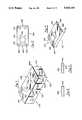
- FIG. 1is an exploded perspective view showing the major components of the integrated down converter and interdigital filter of the present invention
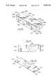
- FIG. 2is a partial perspective view of the portion of the down converter printed circuit board dedicated to receiving the interdigital filter of the present invention
- FIG. 3is a partial perspective view, cut-away, of the opposite side of the printed circuit board of FIG. 2;
- FIG. 4is a top planar view of the first cut piece of the present invention comprising four sides of the interdigital filter housing;
- FIG. 5is a perspective view of the cut piece of FIG. 4 formed into the shape of the housing of the present invention.
- FIG. 6is a top planar view of the second cut piece of the present invention.
- FIG. 7is a perspective view showing the cut piece of FIG. 6 formed into its bracket shape
- FIG. 8is a side planar view of an interior element of the present invention.
- FIG. 9is a side planar view of an end element of the present invention.
- FIG. 10is a bottom planar view of the housing of FIG. 4 with the elements of FIGS. 8 and 9 attached therein;
- FIG. 11illustrates the alignment of an element for attachment to the housing
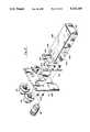
- FIG. 12is an exploded perspective view showing the assembly of the housing to the jack plate
- FIG. 13is a partial perspective view showing the soldered connection of the housing to the jack plate bracket
- FIG. 14is a partial perspective view showing the soldering of the housing to the printed circuit board of the down converter
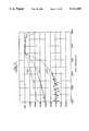
- FIG. 15graphically illustrates the bandwidth performance of the integrated interdigital filter of the present invention.
- FIG. 16graphically illustrates the IF rejection of the integrated interdigital filter of the present invention.
- FIG. 17is a block diagram schematic of the integrated down converter interdigital filter of the present invention.
- FIG. 18is an exploded perspective view showing the major components of an alternative embodiment of the present invention having an integrated down converter and two interdigital filters;
- FIG. 19is a top planar view of the first cut piece used to form four sides of an interdigital filter housing in the alternative embodiment in FIG. 18, showing the holes for the tuning screws in alternative locations;
- FIG. 20is a perspective view of the cut piece of FIG. 19 formed into the shape of one of the interdigital filters housings shown in FIG. 18;
- FIG. 21is a top planar view of the second cut piece of the alternative embodiment formed into a bracket
- FIG. 22is a perspective view showing the cut piece of FIG. 21;
- FIG. 23is an exploded perspective view of the alternative embodiment of FIG. 18, showing the assembly of the housings to the bracket and jack plate;
- FIG. 24is a partial perspective view showing the connection of the housings to the jack plate and bracket;
- FIG. 25is a partial perspective view showing the soldering of the housings to the printed circuit board of the down converter.
- FIG. 26is a block diagram schematic of the alternative embodiment of FIG. 18 through 25, wherein the integrated down converter includes two interdigital filters.
- the integrated down converter and interdigital filter of the present invention 10is shown to include a waterproof housing 20, a single circuit board 30 containing a portion of the down converter section 40 and the interdigital filter section 50.
- a jack plate 70is shown which interconnects to the waterproof housing 20 by means of screws 72.
- the microwave signal coming into the down converter from the antenna, not; shown,is received through the N-connector 80 for delivery into the interdigital filter housing 90 which is then filtered in a predetermined bandwidth such as 2500-2686 MHz by the interdigital filter and delivered to lead 100 for processing by the down converter section 40.
- the resulting electrical output signals from the down converter which corresponds to the filtered microwave signalsare then delivered to the output connectors 120.
- a portion of the interdigital filter 90is the ground plane 130.
- the interdigital filter section 50is incorporated onto the printed circuit board carrying the conventionally available down converter section 40 and is mounted into the waterproof housing 20.
- the jack plate 70mounts over the jack plate gasket 140 which is preferably a closed-cell light density neoprene material. When screws 72 are connected, the combined down converter and interdigital filter is securely protected within the waterproof housing 20.
- the down converter printed circuit board 30is shown.
- This circuit boardis preferably manufactured from 1/16th inch double-clad fiberglass epoxy board.
- the silver cladding on board 30is etched away to define the rectangular ground pad 130.
- the ground plane conductive surface or pad 130has a plurality of holes 200 formed around the outer periphery thereof which provides conductive paths to the opposite side of board 30, designated 210 in FIG. 3.
- the opposite side of board 30, as shown in FIG. 3also has a ground pad 210 etched to remain in place directly under surface 130.
- the formed conductive holes 200insure that ground potential is maintained throughout pad 130.
- the circuit board 30has indents 220 formed on end 230 for mounting to the jack plate 70.
- a formed U-shaped indent 240is formed in the ground plane pad 130 in order to provide an area to place a conductive pad 250 and lead 260 to which wire 100 from the interdigital filter 90 is connected.
- Lead 260delivers the signal from the interdigital filter into the down converter circuitry 40 in a conventional fashion.
- FIG. 4four sides of the housing 90 for the interdigital filter are shown. These sides are designated 400, 410, 420, and 430.
- the piece 440 containing these sidesis cut out of sheet metal through a blanking process.
- a die, not shown,is created to cut the sheet metal in the form shown in FIG. 4.
- Side 400has an indent cutout 450 and whose function will be explained later.
- 400has two cut out holes 460a and 460b which are each 0.218 inches in diameter.
- side 400has two formed holes 470a and 470b which are each cut to a 0.089 inch diameter. Holes 460a, 460b, 470a and 470b are equally spaced apart along line 472.
- opposing side 420has holes 460c, 460d, 470d and 470d equally spaced along line 474.
- the holes on side 400directly oppose the holes on side 420 as indicated by lines 476a through 476d.
- Line 472is 0.375 inches from surface 478 whereas line 474 is 2.267 inches from surface 478 in the preferred embodiment.
- On side 410are located two holes 460e and 460f oriented in opposing corners on side 410.
- side 430has a cut hole 470e centrally located on the edge near side 420.
- small cut-aways 480a and 480bare provided at the junction between side 430 and sides 400 and 420.
- the diecuts out four sides of housing 90 as a single piece 440 as shown in FIG. 4. All holes 460 and 470 are cut and all excess material is removed.
- the material usedis preferably 0.0159 inch one-half hard brass. Holes 470a, 470b, 470c, and 470d are then threaded.
- the piece 440 of FIG. 4is formed into the housing 440 shown in FIG. 5.
- the housing 500has an open end 510 and an open bottom 520.
- the housing 500is formed by bending piece 440 as shown in FIG. 4 along lines 530 and 540 with a forming machine.
- a butt seamis also formed at corners 480a and 480b. In the forming process, ends 550 and 560 simply abut together.
- FIG. 6the details of the jack plate bracket 600 are shown.
- the jack plate bracket 600is also cut out from sheet metal stock into the shape and configuration shown in FIG. 6.
- the rectangular shaped piece formedis cut from 0.0159 inch one-half hard brass stock.
- Six holes 610are cut therein. Each of these holes preferably is 0.125 inches in diameter and are designed to receive rivets as will be subsequently explained.
- four indents 620are cut in opposing sides 630 and 640 of 600.
- substantially circular hole 650is cut from piece 600 to receive the N-connector 80 as shown in FIG. 1.
- Hole 650is 0.500 inch hole with 0.063 inch notches cut out at 45 degree points around the edge.
- piece 600is bent in the shape of formed piece 700 along lines 710 and 720.
- the distance 730 between edges 630 and 640 in the preferred embodimentis 1.750 inches.
- FIGS. 8 and 9are shown the details of the elements of the interdigital filter 90 of the present invention.
- the interior element 800which is cut from copper tubing having a 0.250 inch outer diameter with a 0.031 inch wall thickness.
- element 800is typically 1.00 inches long having an annular region 810 which is typically 0.062 inches deep.
- a conventional screw machineis used to form annular region 810. It can also be formed by turning on a lathe.
- the end element 900is preferably 1.1017 inches long also having an annular region 910 which is also set back 0.062 inches.
- a hole 920is cross drilled through element 900.
- FIG. 10the bottom planar view of the formed housing 500 is shown with tuning elements 800a, 800b, 900a, and 900b mounted therein.
- the spatial location of these tuning elementsis made according to the teachings of Hinshaw, et al. supra.
- each elementis soldered to the side of the housing as indicated by 1000.
- Each elementhas associated with it and directly opposite from it a tuning screw assembly 1010 comprising a tuning screw 1020, and a nut 1030.
- Elements 800 and 900are mounted through the formed holes 460 whereas the screws 1020 are mounted through the formed and threaded holes 470.
- Wire 100is soldered to end element 900b through hole 470e.
- nut 1030 located on the outside of the housing 500is tightened after the elements are tuned to firmly hold the screws 1020 which are threaded into hole 470.
- the arrangement of the tuning elements and the tuning screwsare conventional.
- the element 800 or 900is inserted into hole 460 of the formed housing 500.
- A. threaded collar 1100is placed into the interior of the element 800, 900.
- Collar 1100has a lip 1110 which abuts against end 1130.
- the collar 1100in turn has threads 1120 to receive the threaded end of screw 1020.
- the screwis then tightened into the collar 1100 so that the screw 1020, and the collar 1100 firmly holds end 1130 of the element 800, 900.
- the elementis in perfect alignment and solder 1000 can now be applied.
- the steps in assembling the element 800, 900 to the formed housing 500are as follows:
- annular region 810, 910 of an element 800, 900 rather than being solderedcan be riveted, by curling end 810, 910 over with an anvil tool in a conventional fashion, to housing 500.
- the housing 500 containing the assembled elementsis mounted to the jack plate 70.
- the jack plate bracket 600is mounted to the jack plate 70 by means of rivets of 1200 of the jack plate through holes 1210 and through holes 610 of the jack plate bracket 600.
- the jack plate bracketis then firmly riveted by means of the six rivets 1200 to the jack plate 70.
- the N-connector 80is then inserted through formed hole 1220 of the jack plate and through the cut hole 650 of the jack plate bracket.
- the open end 510 of the housing 500is then mounted to the jack plate bracket 600 as shown in FIG. 13.
- the open end 510is placed against the surface of the jack plate bracket 600 and the end 1230 is soldered at 1300 all along its periphery on sides 420, 410, and 400. This firmly holds the housing to the jack plate bracket 600 which is in turn riveted to the jack plate 70.
- the outer conductor 82, of the N-connecter 80is also soldered at 1310 to the jack plate bracket 600.
- the center conductor 84 of the N-connecter 80is then soldered at 1320, to the terminal element 900 (i.e., the element nearest the jack plate) at hole 920. In this fashion, the interdigital filter of the present invention is firmly attached to the jack plate 70.
- the remaining connecters 120can then be added to the jack plate 70 in a conventional fashion.
- FIG. 14The final assembly of the housing to the down converter is shown in FIG. 14 whereby the jack plate carrying the jack plate bracket 600 with the housing 90 extending therefrom is placed over the circuit board 30 to rest the open bottom on the ground plane conductive surface 130 as shown in FIG. 14.
- the end 1400 of the circuit board 30engages the formed slots 620 of the bracket 600.
- the open end of the housing 90is then soldered at 1410 all the way around the outer periphery of the housing 90 to affix the housing to the surface in order to fully enclose the interior of said housing in a conductive envelope whose potential is at ground as shown in FIG. 14.
- Lead 100is soldered to the pad 250 to electrically interconnect with the conventional down converter circuit 40. As shown in FIG. 10, the farthest element from the jack plate is interconnected with lead 100 and lead 100 carries the filtered microwave signal in the desired bandwidth.
- the interdigital filter 90can now be tuned by adjustment of the screws 1020 to obtain the desired performance. This tuning occurs in a conventional fashion.
- FIGS. 15 and 16are shown the performance of the integrated filter of the present invention designed for the ITFS of frequencies of 2500 to 2686 MHz in comparison to printed filters or integrated dual cavity filters for the same range of frequencies.
- band pass for the interdigital filter described aboveis shown. Note that the band pass is from 250 MHz to 2686 MHz.
- Curve 1500is for a printed filter
- curve 1510is for a dual cavity filter
- curve 1520is for the filter of the present invention.
- This curveshows the sharp band pass for the filter of the present invention.
- the reference line REFis more closely obtained by the interdigital filter thereby showing a lower insertion loss of this filter when compared to the other two filters.
- the one to three dB lower insertion lossimproves the noise figure by a like amount.
- the interdigital filterquickly drops from the reference point to a minus 60 db level.
- the image frequenciesare down 25-40 dB.
- the image frequencies of 2056 MHz and 1870 MHzare much better suppressed with the interdigital filter of the present invention.
- the IF rejection of the present inventionis compared to the dual cavity and printed filters.
- the curve for the printed filters shownis 1600
- the curve for the dual cavityis shown as 1610
- the curve for the interdigital filter of the present inventionis shown as 1620.
- the interdigital filter 1620 curveis approximately 20 to 30 db below that of the dual cavity filter. I.F. rejection is improved for three reasons: (1) the extremely high selectivity characteristics of the interdigital filter of the present invention; (2) the fully enclosed filter allows little leakage of VHF frequencies; and (3) the center conductor 84 of the N-connector 80 is virtually shorted to ground at VHF frequencies due to its tap point 1320 on element 900a.
- FIG. 17the block diagram schematic of the integrated down converter interdigital filter 10 of the present invention is shown interconnected with a microwave antenna 1700 over cable 1701 to the N-connector 80.
- the electrical signal output of the present invention 10is delivered from connector 120a and 120b over cables 1702 and 1703.
- the interdigital filter 50receives the microwave signal from the N-connector 80 over lead 84 and filters the signal for delivery to lead 100 in the desired bandwidth.
- Lead 100inputs the signal to a conventional down converter 40 which processes the signal as follows.
- the signal on lead 100is delivered into an RF low noise amplifier 1710 which delivers the amplified signal to mixer 1720 which is driven by local oscillator 1730 (e.g., 2278 MHz).
- the output of mixer 1720is filtered by a band pass filter 1725 (e.g., 222 MHz to 408 MHz) for delivery to an I.F. amplifier 1740.
- the I.F. amplifierdelivers the electrical output signal to connector 120a and to an isolation network 1750 for delivery to connector 120b.
- the cable that carries the output signal from the I.F. amplifieralso is used to carry power from the DC regulator to other sections of the down converter circuitry.
- the cost of constructing the high performance integrated interdigital filter of the present inventionis significantly less than that of a separate interdigital filter in its own waterproof housing.
- the cost of the interdigital filter of the present inventionis about $20.
- the reason for this low costis due entirely to the integration of the filter onto the down converter board (thereby eliminating the costly jumper cable, waterproof housing, and associated mounting hardware).
- the unique manner of construction for the filteralso lowers costs, being stamped and formed sheet metal brass to create the filter housing 500 and to use the printed circuit board itself as one side of the filter housing.
- FIGS. 1 through 17has been directed to an embodiment of the present invention for the ITFS band, it is expressly understood that an integrated down converter interdigital filter for the MDS band or any other microwave band could also be constructed under the teachings of the present invention.
- FIGS. 18 through 26An alternative embodiment of the present invention having multiple interdigital filters is shown in FIGS. 18 through 26.
- This embodimentpermits a number of separate microwave signal bands received by an appropriate antenna to be filtered and converted to corresponding predetermined output bands by means of a single down converter unit.
- the embodiment shown in FIGS. 18 through 26incorporates two interdigital filters in parallel on the same printed circuit board with the down converter.
- One of these interdigital filtersis tuned to the ITFS band (2500 to 2686 MHz), while the other is tuned to the MDS band (2150 to 2162 MHz).
- ITFS band2500 to 2686 MHz
- MDS band2150 to 2162 MHz
- other microwave bandscould be used as well.
- additional interdigital filterscould be employed in parallel to provide more than two bands.
- FIG. 18corresponds generally to FIG. 1 of the previous embodiment. However, two separate interdigital filter housings 90 are mounted in parallel on the same printed circuit board with the down converter 30.
- FIG. 19corresponds generally to FIG. 4 of the first embodiment, and shows the sheet metal piece 440 use to form four sides of the housing 90 for each of the interdigital filters.
- the location of the tuning screw holes 470a, 470b, 470c, and 470dhave been moved to the top surface 410 of the interdigital filter housing.
- the housing 90is formed by bending the piece 440 of FIG. 19 along lines 530 and 540.
- a butt seamis also formed at corners 480a and 480b.
- FIGS. 21 and 22show two views of the jack plate bracket 600 employed in the alternative embodiment.
- This bracketis formed from sheet metal stock as previously discussed in association with FIGS. 6 and 7.
- the interdigital filter housings 90are mounted to the jack plate 70.
- the jack plate bracket 600is first mounted to the jack plate 70 by means of rivets 1200.
- the N-connector 80is then inserted through the formed hole 1220 of the jack plate and through the cut hole 650 of the jack plate bracket.
- the open end 510 of each housing 90is placed against the surface of the jack plate bracket 600 and soldered all along the edges of the housing sides. This firmly holds the interdigital filter housings 90 to the jack plate bracket 600 which is in turn riveted to the jack plate 70.
- a connector 2300provides electrical connection in parallel for the input microwave signal between the N-connector 80 and the first element of each filter. Either inductive or capacitive coupling of the input microwave signal to the first element of each filter can be employed.
- the shape and dimensions of the respective parallel branches of the connectorcan be designed to provide an input impedance that complements the bandpass characteristics of each filter.
- each branch of the connectorshould provide a low impedance path for microwave signals in the band passed by its respective interdigital filter, but provide a relatively high impedance path for microwave signals in the bands passed by the other interdigital filters.
- FIGS. 18 through 26show a downconverter with two interdigital filters for the ITFS and MDS bands. As shown most clearly in FIGS.
- the connector 2300extends from the N-connector 80 to the first elements in both interdigital filters 90.
- the left interdigital filterpasses the higher ITFS band, while the right filter passes the lower MDS band.
- the branch of the connector 2300 extending to the left filteruses capacitive coupling, which has a lower impedance at high frequencies.
- the branch of the connector extending to the right filteruses inductive coupling, which has a lower impedance at low frequencies.
- FIG. 25The final assembly of the interdigital filter housings to the down converter is shown in FIG. 25 whereby the jack plate carrying the jack plate bracket 600 with the housings 90 extending therefrom is placed over the circuit board 30 to rest the open bottoms of the housings on the ground plane conductive surface of the circuit board.
- the open bottoms of the housings 90is then soldered at 1410 all the way around the outer periphery of the housings 90 to affix the housings to the conductive surface in order to fully enclose the interior of said housings in a conductive envelope whose potential is at ground.
- Leads 100are electrically interconnected with the conventional down converter circuit 40. As shown in FIG.
- the farthest element from the jack plate in each filteris interconnected with a lead 100, which carries the filtered microwave signal in the desired bandwidth.
- the interdigital filter 90can now be tuned by adjustment of the screws 1020 to obtain the desired performance. This tuning occurs in a conventional fashion.
- FIG. 26is analogous to FIG. 17 of the first embodiment.
- the block diagram schematic of an down converter 40 with two interdigital filters 50is shown interconnected with a microwave antenna 1700 over cable 1701 to the N-connector 80.
- the electrical signal output of the present invention 10is delivered from connector 120a and 120b over cables 1702 and 1703.
- the interdigital filters 50receives the microwave signal in parallel from the N-connector 80 and filter the signal for delivery to leads 100 in the desired bands.
- the down converter 40processes the filtered signals as follows.
- the signal on each lead 100is delivered into a respective RF low noise amplifier 1710 which delivers the amplified signal to a respective mixer 1720 which is driven by a common, local oscillator 1730 (e.g., 2278 MHz).
- each respective mixer 1720is filtered by a respective band pass filter 1725 (e.g., 222 MHz to 408 MHz for the ITFS band, and 116 Mhz to 128 MHz for the MDS band) for delivery to an I.F. amplifier 1740.
- the I.F. amplifierdelivers the electrical output signal to connector 120a and to an isolation network 1750 for delivery to connector 120b.
- the cable that carries the output signal from the I.F. amplifieralso is used to carry power from the DC regulator to other sections of the down converter circuitry.
Landscapes
- Physics & Mathematics (AREA)
- Electromagnetism (AREA)
- Input Circuits Of Receivers And Coupling Of Receivers And Audio Equipment (AREA)
Abstract
Description
Claims (8)
Priority Applications (2)
| Application Number | Priority Date | Filing Date | Title |
|---|---|---|---|
| US07/261,557US5020149A (en) | 1987-09-30 | 1988-10-24 | Integrated down converter and interdigital filter apparatus and method for construction thereof |
| US07/355,992US5008956A (en) | 1987-09-30 | 1989-05-23 | Interdigital local oscillator filter apparatus |
Applications Claiming Priority (2)
| Application Number | Priority Date | Filing Date | Title |
|---|---|---|---|
| US07/102,726US4791717A (en) | 1987-09-30 | 1987-09-30 | Interdigital filter apparatus and method for construction |
| US07/261,557US5020149A (en) | 1987-09-30 | 1988-10-24 | Integrated down converter and interdigital filter apparatus and method for construction thereof |
Related Parent Applications (2)
| Application Number | Title | Priority Date | Filing Date |
|---|---|---|---|
| US07/102,726ContinuationUS4791717A (en) | 1987-09-30 | 1987-09-30 | Interdigital filter apparatus and method for construction |
| US07/102,726Continuation-In-PartUS4791717A (en) | 1987-09-30 | 1987-09-30 | Interdigital filter apparatus and method for construction |
Related Child Applications (1)
| Application Number | Title | Priority Date | Filing Date |
|---|---|---|---|
| US07/355,992Continuation-In-PartUS5008956A (en) | 1987-09-30 | 1989-05-23 | Interdigital local oscillator filter apparatus |
Publications (1)
| Publication Number | Publication Date |
|---|---|
| US5020149Atrue US5020149A (en) | 1991-05-28 |
Family
ID=26799671
Family Applications (1)
| Application Number | Title | Priority Date | Filing Date |
|---|---|---|---|
| US07/261,557Expired - LifetimeUS5020149A (en) | 1987-09-30 | 1988-10-24 | Integrated down converter and interdigital filter apparatus and method for construction thereof |
Country Status (1)
| Country | Link |
|---|---|
| US (1) | US5020149A (en) |
Cited By (63)
| Publication number | Priority date | Publication date | Assignee | Title |
|---|---|---|---|---|
| WO1994024783A1 (en)* | 1993-04-16 | 1994-10-27 | Conifer Corporation | Bi-directional tv/data transmission system |
| US5448255A (en)* | 1991-05-30 | 1995-09-05 | Conifer Corporation | Dual band down converter for MMDS/MDS antenna |
| US5471658A (en)* | 1993-03-26 | 1995-11-28 | Iacono; Gene A. | Hermetically sealed communication system with rechargeable battery |
| US5523768A (en)* | 1991-05-30 | 1996-06-04 | Conifer Corporation | Integrated feed and down converter apparatus |
| US5711014A (en)* | 1993-04-05 | 1998-01-20 | Crowley; Robert J. | Antenna transmission coupling arrangement |
| US5838533A (en)* | 1997-03-19 | 1998-11-17 | Eaton Corporation | Housing assembly for circuit components |
| US6049706A (en) | 1998-10-21 | 2000-04-11 | Parkervision, Inc. | Integrated frequency translation and selectivity |
| US6061551A (en) | 1998-10-21 | 2000-05-09 | Parkervision, Inc. | Method and system for down-converting electromagnetic signals |
| US6061555A (en) | 1998-10-21 | 2000-05-09 | Parkervision, Inc. | Method and system for ensuring reception of a communications signal |
| US6091940A (en) | 1998-10-21 | 2000-07-18 | Parkervision, Inc. | Method and system for frequency up-conversion |
| US6094349A (en)* | 1997-08-07 | 2000-07-25 | Robert Bosch Gmbh | Electrical device having a printed-circuit board and method for assembling the device |
| USD432987S (en)* | 1999-10-01 | 2000-10-31 | Smc Kabushiki Kaisha | Signal converter |
| USD433998S (en)* | 1999-10-01 | 2000-11-21 | Smc Kabushiki Kaisha | Signal-input device |
| USD448344S1 (en) | 1999-10-01 | 2001-09-25 | Smc Kabushiki Kaisha | Signal converter |
| US6370371B1 (en) | 1998-10-21 | 2002-04-09 | Parkervision, Inc. | Applications of universal frequency translation |
| US6542722B1 (en) | 1998-10-21 | 2003-04-01 | Parkervision, Inc. | Method and system for frequency up-conversion with variety of transmitter configurations |
| US6545860B1 (en)* | 2000-09-28 | 2003-04-08 | Rockwell Automation Technologies, Inc. | Automation control enclosure having a glandplate to facilitate input and output connections |
| US6560301B1 (en) | 1998-10-21 | 2003-05-06 | Parkervision, Inc. | Integrated frequency translation and selectivity with a variety of filter embodiments |
| US6694128B1 (en) | 1998-08-18 | 2004-02-17 | Parkervision, Inc. | Frequency synthesizer using universal frequency translation technology |
| US6704549B1 (en) | 1999-03-03 | 2004-03-09 | Parkvision, Inc. | Multi-mode, multi-band communication system |
| US6704558B1 (en) | 1999-01-22 | 2004-03-09 | Parkervision, Inc. | Image-reject down-converter and embodiments thereof, such as the family radio service |
| US6813485B2 (en) | 1998-10-21 | 2004-11-02 | Parkervision, Inc. | Method and system for down-converting and up-converting an electromagnetic signal, and transforms for same |
| US20050030130A1 (en)* | 2003-07-31 | 2005-02-10 | Andrew Corporation | Method of manufacturing microwave filter components and microwave filter components formed thereby |
| US6873836B1 (en) | 1999-03-03 | 2005-03-29 | Parkervision, Inc. | Universal platform module and methods and apparatuses relating thereto enabled by universal frequency translation technology |
| US6879817B1 (en) | 1999-04-16 | 2005-04-12 | Parkervision, Inc. | DC offset, re-radiation, and I/Q solutions using universal frequency translation technology |
| US20050192067A1 (en)* | 1993-04-05 | 2005-09-01 | Crowley Robert J. | Radiative focal area antenna transmission coupling arrangement |
| US20050200536A1 (en)* | 1993-04-05 | 2005-09-15 | Crowley Robert J. | Personal communication device connectivity arrangement |
| US6963734B2 (en) | 1999-12-22 | 2005-11-08 | Parkervision, Inc. | Differential frequency down-conversion using techniques of universal frequency translation technology |
| US6975848B2 (en) | 2002-06-04 | 2005-12-13 | Parkervision, Inc. | Method and apparatus for DC offset removal in a radio frequency communication channel |
| US7006805B1 (en) | 1999-01-22 | 2006-02-28 | Parker Vision, Inc. | Aliasing communication system with multi-mode and multi-band functionality and embodiments thereof, such as the family radio service |
| US7010559B2 (en) | 2000-11-14 | 2006-03-07 | Parkervision, Inc. | Method and apparatus for a parallel correlator and applications thereof |
| US7010286B2 (en) | 2000-04-14 | 2006-03-07 | Parkervision, Inc. | Apparatus, system, and method for down-converting and up-converting electromagnetic signals |
| US7027786B1 (en) | 1998-10-21 | 2006-04-11 | Parkervision, Inc. | Carrier and clock recovery using universal frequency translation |
| US7039372B1 (en) | 1998-10-21 | 2006-05-02 | Parkervision, Inc. | Method and system for frequency up-conversion with modulation embodiments |
| US7054296B1 (en) | 1999-08-04 | 2006-05-30 | Parkervision, Inc. | Wireless local area network (WLAN) technology and applications including techniques of universal frequency translation |
| US7072390B1 (en) | 1999-08-04 | 2006-07-04 | Parkervision, Inc. | Wireless local area network (WLAN) using universal frequency translation technology including multi-phase embodiments |
| US7072427B2 (en) | 2001-11-09 | 2006-07-04 | Parkervision, Inc. | Method and apparatus for reducing DC offsets in a communication system |
| US7082171B1 (en) | 1999-11-24 | 2006-07-25 | Parkervision, Inc. | Phase shifting applications of universal frequency translation |
| US7085335B2 (en) | 2001-11-09 | 2006-08-01 | Parkervision, Inc. | Method and apparatus for reducing DC offsets in a communication system |
| US7110435B1 (en) | 1999-03-15 | 2006-09-19 | Parkervision, Inc. | Spread spectrum applications of universal frequency translation |
| US7236754B2 (en) | 1999-08-23 | 2007-06-26 | Parkervision, Inc. | Method and system for frequency up-conversion |
| US7292835B2 (en) | 2000-01-28 | 2007-11-06 | Parkervision, Inc. | Wireless and wired cable modem applications of universal frequency translation technology |
| US7295826B1 (en) | 1998-10-21 | 2007-11-13 | Parkervision, Inc. | Integrated frequency translation and selectivity with gain control functionality, and applications thereof |
| US7321640B2 (en) | 2002-06-07 | 2008-01-22 | Parkervision, Inc. | Active polyphase inverter filter for quadrature signal generation |
| US7379883B2 (en) | 2002-07-18 | 2008-05-27 | Parkervision, Inc. | Networking methods and systems |
| US7425880B2 (en) | 2005-01-20 | 2008-09-16 | Tdk Corporation | Filters with improved rejection band performance |
| US7454453B2 (en) | 2000-11-14 | 2008-11-18 | Parkervision, Inc. | Methods, systems, and computer program products for parallel correlation and applications thereof |
| US7460584B2 (en) | 2002-07-18 | 2008-12-02 | Parkervision, Inc. | Networking methods and systems |
| US7463485B1 (en)* | 2005-10-28 | 2008-12-09 | Yamaichi Electronics U.S.A., Inc. | Circuit board housing and circuit board assembly |
| US7515896B1 (en) | 1998-10-21 | 2009-04-07 | Parkervision, Inc. | Method and system for down-converting an electromagnetic signal, and transforms for same, and aperture relationships |
| US7554508B2 (en) | 2000-06-09 | 2009-06-30 | Parker Vision, Inc. | Phased array antenna applications on universal frequency translation |
| USD597027S1 (en)* | 2006-12-15 | 2009-07-28 | Smc Corporation | Signal input and output converter |
| USD599786S1 (en)* | 2008-09-29 | 2009-09-08 | Baltic Latvian Universal Electronics, Llc | In-line signal processor |
| US7653145B2 (en) | 1999-08-04 | 2010-01-26 | Parkervision, Inc. | Wireless local area network (WLAN) using universal frequency translation technology including multi-phase embodiments and circuit implementations |
| US7693230B2 (en) | 1999-04-16 | 2010-04-06 | Parkervision, Inc. | Apparatus and method of differential IQ frequency up-conversion |
| US7724845B2 (en) | 1999-04-16 | 2010-05-25 | Parkervision, Inc. | Method and system for down-converting and electromagnetic signal, and transforms for same |
| US7773688B2 (en) | 1999-04-16 | 2010-08-10 | Parkervision, Inc. | Method, system, and apparatus for balanced frequency up-conversion, including circuitry to directly couple the outputs of multiple transistors |
| US8295406B1 (en) | 1999-08-04 | 2012-10-23 | Parkervision, Inc. | Universal platform module for a plurality of communication protocols |
| US20130154766A1 (en)* | 2011-12-20 | 2013-06-20 | Schaffner Emv Ag | Feed through emc filter |
| USD737765S1 (en)* | 2014-02-20 | 2015-09-01 | Smc Corporation | Signal input and output converter |
| USD920909S1 (en)* | 2018-04-25 | 2021-06-01 | Smc Corporation | Signal input and output converter |
| US11026338B2 (en)* | 2018-09-19 | 2021-06-01 | Delta Electronics, Inc. | Waterproof casing of outdoor wireless electronic device |
| US11147180B2 (en)* | 2018-09-19 | 2021-10-12 | Delta Electronics, Inc. | Waterproof casing |
Citations (9)
| Publication number | Priority date | Publication date | Assignee | Title |
|---|---|---|---|---|
| US3593223A (en)* | 1968-08-15 | 1971-07-13 | Int Standard Electric Corp | Electric wave filter employing interdigital line structures |
| US4019141A (en)* | 1976-03-22 | 1977-04-19 | Motorola, Inc. | Preselector cavity arrangement and RF selectivity assembly |
| US4112398A (en)* | 1976-08-05 | 1978-09-05 | Hughes Aircraft Company | Temperature compensated microwave filter |
| US4152671A (en)* | 1977-07-25 | 1979-05-01 | Atari, Inc. | Oscillator-modulator apparatus and method therefor |
| US4384367A (en)* | 1980-02-12 | 1983-05-17 | Theta-Com Of California | MDS Receiver |
| US4569000A (en)* | 1981-11-13 | 1986-02-04 | Alps Electric Co., Ltd. | Mounting structure for electric elements |
| US4772862A (en)* | 1985-12-17 | 1988-09-20 | Matsushita Electric Industrial Co., Ltd. | Filter apparatus |
| US4791717A (en)* | 1987-09-30 | 1988-12-20 | Conifer Corporation | Interdigital filter apparatus and method for construction |
| US4831498A (en)* | 1987-07-23 | 1989-05-16 | Uniden Corporation | Shield structure for circuit on circuit board |
- 1988
- 1988-10-24USUS07/261,557patent/US5020149A/ennot_activeExpired - Lifetime
Patent Citations (9)
| Publication number | Priority date | Publication date | Assignee | Title |
|---|---|---|---|---|
| US3593223A (en)* | 1968-08-15 | 1971-07-13 | Int Standard Electric Corp | Electric wave filter employing interdigital line structures |
| US4019141A (en)* | 1976-03-22 | 1977-04-19 | Motorola, Inc. | Preselector cavity arrangement and RF selectivity assembly |
| US4112398A (en)* | 1976-08-05 | 1978-09-05 | Hughes Aircraft Company | Temperature compensated microwave filter |
| US4152671A (en)* | 1977-07-25 | 1979-05-01 | Atari, Inc. | Oscillator-modulator apparatus and method therefor |
| US4384367A (en)* | 1980-02-12 | 1983-05-17 | Theta-Com Of California | MDS Receiver |
| US4569000A (en)* | 1981-11-13 | 1986-02-04 | Alps Electric Co., Ltd. | Mounting structure for electric elements |
| US4772862A (en)* | 1985-12-17 | 1988-09-20 | Matsushita Electric Industrial Co., Ltd. | Filter apparatus |
| US4831498A (en)* | 1987-07-23 | 1989-05-16 | Uniden Corporation | Shield structure for circuit on circuit board |
| US4791717A (en)* | 1987-09-30 | 1988-12-20 | Conifer Corporation | Interdigital filter apparatus and method for construction |
Cited By (141)
| Publication number | Priority date | Publication date | Assignee | Title |
|---|---|---|---|---|
| US5448255A (en)* | 1991-05-30 | 1995-09-05 | Conifer Corporation | Dual band down converter for MMDS/MDS antenna |
| US5523768A (en)* | 1991-05-30 | 1996-06-04 | Conifer Corporation | Integrated feed and down converter apparatus |
| US5471658A (en)* | 1993-03-26 | 1995-11-28 | Iacono; Gene A. | Hermetically sealed communication system with rechargeable battery |
| US7881664B2 (en) | 1993-04-05 | 2011-02-01 | Ambit Corp | Personal wireless communication device connectivity arrangement within an RF restricted environment |
| US7421253B2 (en) | 1993-04-05 | 2008-09-02 | Ambit Corp | Personal wireless communication device wireless connectivity arrangement |
| US20050192067A1 (en)* | 1993-04-05 | 2005-09-01 | Crowley Robert J. | Radiative focal area antenna transmission coupling arrangement |
| US20050200536A1 (en)* | 1993-04-05 | 2005-09-15 | Crowley Robert J. | Personal communication device connectivity arrangement |
| US5711014A (en)* | 1993-04-05 | 1998-01-20 | Crowley; Robert J. | Antenna transmission coupling arrangement |
| US20070173302A1 (en)* | 1993-04-05 | 2007-07-26 | Crowley Robert J | Radiative focal area antenna transmission coupling arrangement |
| US7904124B2 (en) | 1993-04-05 | 2011-03-08 | Ambit Corp | Radiative focal area antenna transmission coupling arrangement |
| US7400858B2 (en) | 1993-04-05 | 2008-07-15 | Ambit Corp | Radiative focal area antenna transmission coupling arrangement |
| US7580733B2 (en) | 1993-04-05 | 2009-08-25 | Ambit Corp | Personal communication device connectivity arrangement |
| US20100178880A1 (en)* | 1993-04-05 | 2010-07-15 | Crowley Robert J | Radiative focal area antenna transmission coupling arrangement |
| US6112106A (en)* | 1993-04-05 | 2000-08-29 | Crowley; Robert J. | Antenna transmission coupling arrangement |
| WO1994024783A1 (en)* | 1993-04-16 | 1994-10-27 | Conifer Corporation | Bi-directional tv/data transmission system |
| US5437052A (en)* | 1993-04-16 | 1995-07-25 | Conifer Corporation | MMDS over-the-air bi-directional TV/data transmission system and method therefor |
| AU679524B2 (en)* | 1993-04-16 | 1997-07-03 | Conifer Corporation | Bi-directional TV/data transmission system |
| US5394559A (en)* | 1993-04-16 | 1995-02-28 | Conifer Corporation | MMDS/ITFS bi-directional over-the-air transmission system and method therefor |
| US5838533A (en)* | 1997-03-19 | 1998-11-17 | Eaton Corporation | Housing assembly for circuit components |
| US6094349A (en)* | 1997-08-07 | 2000-07-25 | Robert Bosch Gmbh | Electrical device having a printed-circuit board and method for assembling the device |
| US6694128B1 (en) | 1998-08-18 | 2004-02-17 | Parkervision, Inc. | Frequency synthesizer using universal frequency translation technology |
| US7865177B2 (en) | 1998-10-21 | 2011-01-04 | Parkervision, Inc. | Method and system for down-converting an electromagnetic signal, and transforms for same, and aperture relationships |
| US7321735B1 (en) | 1998-10-21 | 2008-01-22 | Parkervision, Inc. | Optical down-converter using universal frequency translation technology |
| US7529522B2 (en) | 1998-10-21 | 2009-05-05 | Parkervision, Inc. | Apparatus and method for communicating an input signal in polar representation |
| US6560301B1 (en) | 1998-10-21 | 2003-05-06 | Parkervision, Inc. | Integrated frequency translation and selectivity with a variety of filter embodiments |
| US6580902B1 (en) | 1998-10-21 | 2003-06-17 | Parkervision, Inc. | Frequency translation using optimized switch structures |
| US6647250B1 (en) | 1998-10-21 | 2003-11-11 | Parkervision, Inc. | Method and system for ensuring reception of a communications signal |
| US6687493B1 (en) | 1998-10-21 | 2004-02-03 | Parkervision, Inc. | Method and circuit for down-converting a signal using a complementary FET structure for improved dynamic range |
| US6421534B1 (en) | 1998-10-21 | 2002-07-16 | Parkervision, Inc. | Integrated frequency translation and selectivity |
| US7515896B1 (en) | 1998-10-21 | 2009-04-07 | Parkervision, Inc. | Method and system for down-converting an electromagnetic signal, and transforms for same, and aperture relationships |
| US7620378B2 (en) | 1998-10-21 | 2009-11-17 | Parkervision, Inc. | Method and system for frequency up-conversion with modulation embodiments |
| US6798351B1 (en) | 1998-10-21 | 2004-09-28 | Parkervision, Inc. | Automated meter reader applications of universal frequency translation |
| US6813485B2 (en) | 1998-10-21 | 2004-11-02 | Parkervision, Inc. | Method and system for down-converting and up-converting an electromagnetic signal, and transforms for same |
| US6836650B2 (en) | 1998-10-21 | 2004-12-28 | Parkervision, Inc. | Methods and systems for down-converting electromagnetic signals, and applications thereof |
| US8340618B2 (en) | 1998-10-21 | 2012-12-25 | Parkervision, Inc. | Method and system for down-converting an electromagnetic signal, and transforms for same, and aperture relationships |
| US7693502B2 (en) | 1998-10-21 | 2010-04-06 | Parkervision, Inc. | Method and system for down-converting an electromagnetic signal, transforms for same, and aperture relationships |
| US7697916B2 (en) | 1998-10-21 | 2010-04-13 | Parkervision, Inc. | Applications of universal frequency translation |
| US8233855B2 (en) | 1998-10-21 | 2012-07-31 | Parkervision, Inc. | Up-conversion based on gated information signal |
| US6370371B1 (en) | 1998-10-21 | 2002-04-09 | Parkervision, Inc. | Applications of universal frequency translation |
| US6353735B1 (en) | 1998-10-21 | 2002-03-05 | Parkervision, Inc. | MDG method for output signal generation |
| US6091940A (en) | 1998-10-21 | 2000-07-18 | Parkervision, Inc. | Method and system for frequency up-conversion |
| US6266518B1 (en) | 1998-10-21 | 2001-07-24 | Parkervision, Inc. | Method and system for down-converting electromagnetic signals by sampling and integrating over apertures |
| US7389100B2 (en) | 1998-10-21 | 2008-06-17 | Parkervision, Inc. | Method and circuit for down-converting a signal |
| US7826817B2 (en) | 1998-10-21 | 2010-11-02 | Parker Vision, Inc. | Applications of universal frequency translation |
| US8190108B2 (en) | 1998-10-21 | 2012-05-29 | Parkervision, Inc. | Method and system for frequency up-conversion |
| US7016663B2 (en) | 1998-10-21 | 2006-03-21 | Parkervision, Inc. | Applications of universal frequency translation |
| US7027786B1 (en) | 1998-10-21 | 2006-04-11 | Parkervision, Inc. | Carrier and clock recovery using universal frequency translation |
| US7039372B1 (en) | 1998-10-21 | 2006-05-02 | Parkervision, Inc. | Method and system for frequency up-conversion with modulation embodiments |
| US7050508B2 (en) | 1998-10-21 | 2006-05-23 | Parkervision, Inc. | Method and system for frequency up-conversion with a variety of transmitter configurations |
| US8190116B2 (en) | 1998-10-21 | 2012-05-29 | Parker Vision, Inc. | Methods and systems for down-converting a signal using a complementary transistor structure |
| US6542722B1 (en) | 1998-10-21 | 2003-04-01 | Parkervision, Inc. | Method and system for frequency up-conversion with variety of transmitter configurations |
| US8160534B2 (en) | 1998-10-21 | 2012-04-17 | Parkervision, Inc. | Applications of universal frequency translation |
| US7076011B2 (en) | 1998-10-21 | 2006-07-11 | Parkervision, Inc. | Integrated frequency translation and selectivity |
| US6061555A (en) | 1998-10-21 | 2000-05-09 | Parkervision, Inc. | Method and system for ensuring reception of a communications signal |
| US7376410B2 (en) | 1998-10-21 | 2008-05-20 | Parkervision, Inc. | Methods and systems for down-converting a signal using a complementary transistor structure |
| US8019291B2 (en) | 1998-10-21 | 2011-09-13 | Parkervision, Inc. | Method and system for frequency down-conversion and frequency up-conversion |
| US6061551A (en) | 1998-10-21 | 2000-05-09 | Parkervision, Inc. | Method and system for down-converting electromagnetic signals |
| US7308242B2 (en) | 1998-10-21 | 2007-12-11 | Parkervision, Inc. | Method and system for down-converting and up-converting an electromagnetic signal, and transforms for same |
| US7194246B2 (en) | 1998-10-21 | 2007-03-20 | Parkervision, Inc. | Methods and systems for down-converting a signal using a complementary transistor structure |
| US7218907B2 (en) | 1998-10-21 | 2007-05-15 | Parkervision, Inc. | Method and circuit for down-converting a signal |
| US7936022B2 (en) | 1998-10-21 | 2011-05-03 | Parkervision, Inc. | Method and circuit for down-converting a signal |
| US7295826B1 (en) | 1998-10-21 | 2007-11-13 | Parkervision, Inc. | Integrated frequency translation and selectivity with gain control functionality, and applications thereof |
| US7937059B2 (en) | 1998-10-21 | 2011-05-03 | Parkervision, Inc. | Converting an electromagnetic signal via sub-sampling |
| US6049706A (en) | 1998-10-21 | 2000-04-11 | Parkervision, Inc. | Integrated frequency translation and selectivity |
| US7245886B2 (en) | 1998-10-21 | 2007-07-17 | Parkervision, Inc. | Method and system for frequency up-conversion with modulation embodiments |
| US7006805B1 (en) | 1999-01-22 | 2006-02-28 | Parker Vision, Inc. | Aliasing communication system with multi-mode and multi-band functionality and embodiments thereof, such as the family radio service |
| US6704558B1 (en) | 1999-01-22 | 2004-03-09 | Parkervision, Inc. | Image-reject down-converter and embodiments thereof, such as the family radio service |
| US6704549B1 (en) | 1999-03-03 | 2004-03-09 | Parkvision, Inc. | Multi-mode, multi-band communication system |
| US7483686B2 (en) | 1999-03-03 | 2009-01-27 | Parkervision, Inc. | Universal platform module and methods and apparatuses relating thereto enabled by universal frequency translation technology |
| US6873836B1 (en) | 1999-03-03 | 2005-03-29 | Parkervision, Inc. | Universal platform module and methods and apparatuses relating thereto enabled by universal frequency translation technology |
| US7599421B2 (en) | 1999-03-15 | 2009-10-06 | Parkervision, Inc. | Spread spectrum applications of universal frequency translation |
| US7110435B1 (en) | 1999-03-15 | 2006-09-19 | Parkervision, Inc. | Spread spectrum applications of universal frequency translation |
| US7773688B2 (en) | 1999-04-16 | 2010-08-10 | Parkervision, Inc. | Method, system, and apparatus for balanced frequency up-conversion, including circuitry to directly couple the outputs of multiple transistors |
| US7724845B2 (en) | 1999-04-16 | 2010-05-25 | Parkervision, Inc. | Method and system for down-converting and electromagnetic signal, and transforms for same |
| US8224281B2 (en) | 1999-04-16 | 2012-07-17 | Parkervision, Inc. | Down-conversion of an electromagnetic signal with feedback control |
| US7929638B2 (en) | 1999-04-16 | 2011-04-19 | Parkervision, Inc. | Wireless local area network (WLAN) using universal frequency translation technology including multi-phase embodiments |
| US8036304B2 (en) | 1999-04-16 | 2011-10-11 | Parkervision, Inc. | Apparatus and method of differential IQ frequency up-conversion |
| US8223898B2 (en) | 1999-04-16 | 2012-07-17 | Parkervision, Inc. | Method and system for down-converting an electromagnetic signal, and transforms for same |
| US8229023B2 (en) | 1999-04-16 | 2012-07-24 | Parkervision, Inc. | Wireless local area network (WLAN) using universal frequency translation technology including multi-phase embodiments |
| US8077797B2 (en) | 1999-04-16 | 2011-12-13 | Parkervision, Inc. | Method, system, and apparatus for balanced frequency up-conversion of a baseband signal |
| US6879817B1 (en) | 1999-04-16 | 2005-04-12 | Parkervision, Inc. | DC offset, re-radiation, and I/Q solutions using universal frequency translation technology |
| US7539474B2 (en) | 1999-04-16 | 2009-05-26 | Parkervision, Inc. | DC offset, re-radiation, and I/Q solutions using universal frequency translation technology |
| US7693230B2 (en) | 1999-04-16 | 2010-04-06 | Parkervision, Inc. | Apparatus and method of differential IQ frequency up-conversion |
| US7190941B2 (en) | 1999-04-16 | 2007-03-13 | Parkervision, Inc. | Method and apparatus for reducing DC offsets in communication systems using universal frequency translation technology |
| US7224749B2 (en) | 1999-04-16 | 2007-05-29 | Parkervision, Inc. | Method and apparatus for reducing re-radiation using techniques of universal frequency translation technology |
| US7894789B2 (en) | 1999-04-16 | 2011-02-22 | Parkervision, Inc. | Down-conversion of an electromagnetic signal with feedback control |
| US7272164B2 (en) | 1999-04-16 | 2007-09-18 | Parkervision, Inc. | Reducing DC offsets using spectral spreading |
| US8594228B2 (en) | 1999-04-16 | 2013-11-26 | Parkervision, Inc. | Apparatus and method of differential IQ frequency up-conversion |
| US7072390B1 (en) | 1999-08-04 | 2006-07-04 | Parkervision, Inc. | Wireless local area network (WLAN) using universal frequency translation technology including multi-phase embodiments |
| US8295406B1 (en) | 1999-08-04 | 2012-10-23 | Parkervision, Inc. | Universal platform module for a plurality of communication protocols |
| US7054296B1 (en) | 1999-08-04 | 2006-05-30 | Parkervision, Inc. | Wireless local area network (WLAN) technology and applications including techniques of universal frequency translation |
| US7653145B2 (en) | 1999-08-04 | 2010-01-26 | Parkervision, Inc. | Wireless local area network (WLAN) using universal frequency translation technology including multi-phase embodiments and circuit implementations |
| US7546096B2 (en) | 1999-08-23 | 2009-06-09 | Parkervision, Inc. | Frequency up-conversion using a harmonic generation and extraction module |
| US7236754B2 (en) | 1999-08-23 | 2007-06-26 | Parkervision, Inc. | Method and system for frequency up-conversion |
| USD433998S (en)* | 1999-10-01 | 2000-11-21 | Smc Kabushiki Kaisha | Signal-input device |
| USD432987S (en)* | 1999-10-01 | 2000-10-31 | Smc Kabushiki Kaisha | Signal converter |
| USD448344S1 (en) | 1999-10-01 | 2001-09-25 | Smc Kabushiki Kaisha | Signal converter |
| US7082171B1 (en) | 1999-11-24 | 2006-07-25 | Parkervision, Inc. | Phase shifting applications of universal frequency translation |
| US7379515B2 (en) | 1999-11-24 | 2008-05-27 | Parkervision, Inc. | Phased array antenna applications of universal frequency translation |
| US6963734B2 (en) | 1999-12-22 | 2005-11-08 | Parkervision, Inc. | Differential frequency down-conversion using techniques of universal frequency translation technology |
| US7292835B2 (en) | 2000-01-28 | 2007-11-06 | Parkervision, Inc. | Wireless and wired cable modem applications of universal frequency translation technology |
| US7107028B2 (en) | 2000-04-14 | 2006-09-12 | Parkervision, Inc. | Apparatus, system, and method for up converting electromagnetic signals |
| US7218899B2 (en) | 2000-04-14 | 2007-05-15 | Parkervision, Inc. | Apparatus, system, and method for up-converting electromagnetic signals |
| US7386292B2 (en) | 2000-04-14 | 2008-06-10 | Parkervision, Inc. | Apparatus, system, and method for down-converting and up-converting electromagnetic signals |
| US7822401B2 (en) | 2000-04-14 | 2010-10-26 | Parkervision, Inc. | Apparatus and method for down-converting electromagnetic signals by controlled charging and discharging of a capacitor |
| US8295800B2 (en) | 2000-04-14 | 2012-10-23 | Parkervision, Inc. | Apparatus and method for down-converting electromagnetic signals by controlled charging and discharging of a capacitor |
| US7010286B2 (en) | 2000-04-14 | 2006-03-07 | Parkervision, Inc. | Apparatus, system, and method for down-converting and up-converting electromagnetic signals |
| US7496342B2 (en) | 2000-04-14 | 2009-02-24 | Parkervision, Inc. | Down-converting electromagnetic signals, including controlled discharge of capacitors |
| US7554508B2 (en) | 2000-06-09 | 2009-06-30 | Parker Vision, Inc. | Phased array antenna applications on universal frequency translation |
| US6545860B1 (en)* | 2000-09-28 | 2003-04-08 | Rockwell Automation Technologies, Inc. | Automation control enclosure having a glandplate to facilitate input and output connections |
| US7233969B2 (en) | 2000-11-14 | 2007-06-19 | Parkervision, Inc. | Method and apparatus for a parallel correlator and applications thereof |
| US7454453B2 (en) | 2000-11-14 | 2008-11-18 | Parkervision, Inc. | Methods, systems, and computer program products for parallel correlation and applications thereof |
| US7991815B2 (en) | 2000-11-14 | 2011-08-02 | Parkervision, Inc. | Methods, systems, and computer program products for parallel correlation and applications thereof |
| US7433910B2 (en) | 2000-11-14 | 2008-10-07 | Parkervision, Inc. | Method and apparatus for the parallel correlator and applications thereof |
| US7010559B2 (en) | 2000-11-14 | 2006-03-07 | Parkervision, Inc. | Method and apparatus for a parallel correlator and applications thereof |
| US7653158B2 (en) | 2001-11-09 | 2010-01-26 | Parkervision, Inc. | Gain control in a communication channel |
| US7085335B2 (en) | 2001-11-09 | 2006-08-01 | Parkervision, Inc. | Method and apparatus for reducing DC offsets in a communication system |
| US8446994B2 (en) | 2001-11-09 | 2013-05-21 | Parkervision, Inc. | Gain control in a communication channel |
| US7072427B2 (en) | 2001-11-09 | 2006-07-04 | Parkervision, Inc. | Method and apparatus for reducing DC offsets in a communication system |
| US6975848B2 (en) | 2002-06-04 | 2005-12-13 | Parkervision, Inc. | Method and apparatus for DC offset removal in a radio frequency communication channel |
| US7321640B2 (en) | 2002-06-07 | 2008-01-22 | Parkervision, Inc. | Active polyphase inverter filter for quadrature signal generation |
| US8160196B2 (en) | 2002-07-18 | 2012-04-17 | Parkervision, Inc. | Networking methods and systems |
| US7379883B2 (en) | 2002-07-18 | 2008-05-27 | Parkervision, Inc. | Networking methods and systems |
| US8407061B2 (en) | 2002-07-18 | 2013-03-26 | Parkervision, Inc. | Networking methods and systems |
| US7460584B2 (en) | 2002-07-18 | 2008-12-02 | Parkervision, Inc. | Networking methods and systems |
| US6904666B2 (en) | 2003-07-31 | 2005-06-14 | Andrew Corporation | Method of manufacturing microwave filter components and microwave filter components formed thereby |
| US20050030130A1 (en)* | 2003-07-31 | 2005-02-10 | Andrew Corporation | Method of manufacturing microwave filter components and microwave filter components formed thereby |
| US7425880B2 (en) | 2005-01-20 | 2008-09-16 | Tdk Corporation | Filters with improved rejection band performance |
| US7463485B1 (en)* | 2005-10-28 | 2008-12-09 | Yamaichi Electronics U.S.A., Inc. | Circuit board housing and circuit board assembly |
| USD597027S1 (en)* | 2006-12-15 | 2009-07-28 | Smc Corporation | Signal input and output converter |
| USD599786S1 (en)* | 2008-09-29 | 2009-09-08 | Baltic Latvian Universal Electronics, Llc | In-line signal processor |
| KR20130071385A (en)* | 2011-12-20 | 2013-06-28 | 샤프너 에엠파우 아게 | Feed through emc filter |
| JP2013131747A (en)* | 2011-12-20 | 2013-07-04 | Schaffner Emv Ag | Feed-through emc filter |
| US20130154766A1 (en)* | 2011-12-20 | 2013-06-20 | Schaffner Emv Ag | Feed through emc filter |
| US9019043B2 (en)* | 2011-12-20 | 2015-04-28 | Schaffner Emv Ag | Feed through EMC filter |
| KR102043604B1 (en) | 2011-12-20 | 2019-11-12 | 샤프너 에엠파우 아게 | Feed through emc filter |
| USD737765S1 (en)* | 2014-02-20 | 2015-09-01 | Smc Corporation | Signal input and output converter |
| USD920909S1 (en)* | 2018-04-25 | 2021-06-01 | Smc Corporation | Signal input and output converter |
| USD949788S1 (en) | 2018-04-25 | 2022-04-26 | Smc Corporation | Signal input and output converter |
| US11026338B2 (en)* | 2018-09-19 | 2021-06-01 | Delta Electronics, Inc. | Waterproof casing of outdoor wireless electronic device |
| US11147180B2 (en)* | 2018-09-19 | 2021-10-12 | Delta Electronics, Inc. | Waterproof casing |
Similar Documents
| Publication | Publication Date | Title |
|---|---|---|
| US5020149A (en) | Integrated down converter and interdigital filter apparatus and method for construction thereof | |
| US4791717A (en) | Interdigital filter apparatus and method for construction | |
| US5008956A (en) | Interdigital local oscillator filter apparatus | |
| US5446729A (en) | Compact, low-intermodulation multiplexer employing interdigital filters | |
| US5610620A (en) | Combination antenna | |
| KR100313590B1 (en) | Structure of tuner and cable modem tuner using it | |
| DE69326118T2 (en) | Polarization separator and mode converter for waveguide microstrip conductors in microwave devices | |
| WO2000046931A1 (en) | Integrated antenna coupler element | |
| GB2274949A (en) | Modular tuner and demodulator | |
| US4353132A (en) | Double superheterodyne tuner | |
| KR20000016459A (en) | Integrated filter | |
| US20050136876A1 (en) | Tower mounted amplifier filter and manufacturing method thereof | |
| US4569000A (en) | Mounting structure for electric elements | |
| EP1135826B1 (en) | Microstrip filter device | |
| US6563394B1 (en) | Coaxial circulator with coplanar Y-shaped conductor and ground patterns | |
| JP3385909B2 (en) | Filter and transceiver | |
| EP1033821B1 (en) | DECT transceiver module | |
| DE19909071C2 (en) | DECT radio module | |
| EP1006667B1 (en) | Receiver | |
| JPH01241901A (en) | Filter | |
| JP2000022379A (en) | Digital communication equipment | |
| EP0913924A1 (en) | Tuner for receiving digital television signals | |
| KR900000485B1 (en) | Manufacturing method of tuner housing | |
| JPS5825608Y2 (en) | Structure of directional filter | |
| EP0207523A2 (en) | Radio-frequency signal processing unit |
Legal Events
| Date | Code | Title | Description |
|---|---|---|---|
| AS | Assignment | Owner name:CONIFER CORPORATION, 1400 NORTH ROOSEVELT, BURLING Free format text:ASSIGNMENT OF ASSIGNORS INTEREST.;ASSIGNOR:HEMMIE, DALE L.;REEL/FRAME:004970/0558 Effective date:19881020 Owner name:CONIFER CORPORATION, IOWA Free format text:ASSIGNMENT OF ASSIGNORS INTEREST;ASSIGNOR:HEMMIE, DALE L.;REEL/FRAME:004970/0558 Effective date:19881020 | |
| FEPP | Fee payment procedure | Free format text:PAYOR NUMBER ASSIGNED (ORIGINAL EVENT CODE: ASPN); ENTITY STATUS OF PATENT OWNER: LARGE ENTITY | |
| STCF | Information on status: patent grant | Free format text:PATENTED CASE | |
| FPAY | Fee payment | Year of fee payment:4 | |
| FEPP | Fee payment procedure | Free format text:PAYOR NUMBER ASSIGNED (ORIGINAL EVENT CODE: ASPN); ENTITY STATUS OF PATENT OWNER: LARGE ENTITY Free format text:PAYER NUMBER DE-ASSIGNED (ORIGINAL EVENT CODE: RMPN); ENTITY STATUS OF PATENT OWNER: LARGE ENTITY | |
| FPAY | Fee payment | Year of fee payment:8 | |
| FEPP | Fee payment procedure | Free format text:PAT HOLDER NO LONGER CLAIMS SMALL ENTITY STATUS, ENTITY STATUS SET TO UNDISCOUNTED (ORIGINAL EVENT CODE: STOL); ENTITY STATUS OF PATENT OWNER: LARGE ENTITY | |
| FPAY | Fee payment | Year of fee payment:12 | |
| REMI | Maintenance fee reminder mailed |