US5019695A - Puncher and method of controlling the puncher - Google Patents
Puncher and method of controlling the puncherDownload PDFInfo
- Publication number
- US5019695A US5019695AUS07/437,367US43736789AUS5019695AUS 5019695 AUS5019695 AUS 5019695AUS 43736789 AUS43736789 AUS 43736789AUS 5019695 AUS5019695 AUS 5019695A
- Authority
- US
- United States
- Prior art keywords
- card
- conveyance
- target
- data
- sum
- Prior art date
- Legal status (The legal status is an assumption and is not a legal conclusion. Google has not performed a legal analysis and makes no representation as to the accuracy of the status listed.)
- Expired - Lifetime
Links
Images


Classifications
- G—PHYSICS
- G07—CHECKING-DEVICES
- G07B—TICKET-ISSUING APPARATUS; FARE-REGISTERING APPARATUS; FRANKING APPARATUS
- G07B11/00—Apparatus for validating or cancelling issued tickets
- G07B11/02—Apparatus for validating or cancelling issued tickets for validating inserted tickets
- G07B11/07—Apparatus for validating or cancelling issued tickets for validating inserted tickets by separating part of ticket
- G—PHYSICS
- G06—COMPUTING OR CALCULATING; COUNTING
- G06K—GRAPHICAL DATA READING; PRESENTATION OF DATA; RECORD CARRIERS; HANDLING RECORD CARRIERS
- G06K1/00—Methods or arrangements for marking the record carrier in digital fashion
- G06K1/02—Methods or arrangements for marking the record carrier in digital fashion by punching
- G—PHYSICS
- G06—COMPUTING OR CALCULATING; COUNTING
- G06Q—INFORMATION AND COMMUNICATION TECHNOLOGY [ICT] SPECIALLY ADAPTED FOR ADMINISTRATIVE, COMMERCIAL, FINANCIAL, MANAGERIAL OR SUPERVISORY PURPOSES; SYSTEMS OR METHODS SPECIALLY ADAPTED FOR ADMINISTRATIVE, COMMERCIAL, FINANCIAL, MANAGERIAL OR SUPERVISORY PURPOSES, NOT OTHERWISE PROVIDED FOR
- G06Q20/00—Payment architectures, schemes or protocols
- G06Q20/30—Payment architectures, schemes or protocols characterised by the use of specific devices or networks
- G06Q20/34—Payment architectures, schemes or protocols characterised by the use of specific devices or networks using cards, e.g. integrated circuit [IC] cards or magnetic cards
- G06Q20/343—Cards including a counter
- G06Q20/3433—Cards including a counter the counter having monetary units
- G—PHYSICS
- G07—CHECKING-DEVICES
- G07F—COIN-FREED OR LIKE APPARATUS
- G07F7/00—Mechanisms actuated by objects other than coins to free or to actuate vending, hiring, coin or paper currency dispensing or refunding apparatus
- G07F7/02—Mechanisms actuated by objects other than coins to free or to actuate vending, hiring, coin or paper currency dispensing or refunding apparatus by keys or other credit registering devices
Definitions
- the present inventionrelates to card punchers which punch cards as the yardstick of the sum of money paid by the cards used as coupon tickets, or to get tickets on omnibuses and/or electric trains and method of control the punchers.
- Cards of such typestore a predetermined number of records or a predetermined sum of money in the respective magnetic record sections formed on their backs. If the card is inserted into a card insertion slot in a card handling device, data on the sum of money stored in the magnetic record section is read, an amount of money corresponding to the use of the card is subtracted from the sum of the money and the card is then returned to the user. In order to visually display the remaining sum of money to the user, the card is punched at its predetermined position. Since the position of the punched hole indicates the remaining sum of money, it must be accurate.
- an arrangementis proposed conventionally which when the card arrives at a position where it should be punched, it is stopped by a brake or a clutch and a punching mechanism is actuated to punch the card, or an arrangement is proposed in which a motor as a source of power to convey the card is slowed down to position a punched hole.
- the punching mechanismIn the arrangement in which a punched hole is positioned using the brake or clutch, the punching mechanism is complicated and large-sized, so that the space where the arrangement is to be accommodated is forced to be too small, and hence the arrangement cannot be used.
- the motorIn the arrangement in which the motor is slowed down, a time required for processing one card is increased, and an increase in the temperature of the motor would reduce the service life of the motor itself and the circuit parts in the vicinity of the motor.
- a memorystores data on a target quantity of conveyance of a card corresponding to the position where the card is punched.
- a card conveyeris driven to convey the card by a quantity corresponding to the data on the target quantity of conveyance stored in the memory.
- a quantity of coast of the card after the drive of the conveyer is terminatedis measured.
- the cardis punched if the sum of the target quantity of conveyance and the measured quantity of coast of the card is within an allowable limit.
- the data on the target quantity of conveyanceis set in correspondence to the difference between the distance from a predetermined reference position to the position where the card is punched and a predicted coasting distance of the card.
- the data on the target quantity of conveyance in the memoryis corrected such that the sum of the target quantity of conveyance and the measured quantity of coast falls within a predetermined allowable limit if otherwise.
- the cardis then returned to a position where the card punching is started, and card punching is retried.
- the sum of the target quantity of conveyance and the measured quantity of coastis compared with a standard value corresponding to the position where the card is punched.
- the target quantity of conveyanceis increased by a quantity corresponding to the difference between the standard value and the sum if the sum is smaller than the standard value.
- the target quantity of conveyanceis reduced by a quantity corresponding to the difference between the sum and the standard value if the sum is larger than the standard value.
- a card punchercomprises a reversible motor for conveying a card, a conveyer belt driven by the motor for conveying a card to its a target punching position, a mechanism for punching the card, an encoder rotated synchronously with the motor for outputting pulses proportional in number to the quantity of conveyance of the card, a sensor for sensing the passage of the leading or trailing end of the card through a predetermined position on the conveyer belt, a memory for storing data on a standard value indicative of the quantity of conveyance of the card from the predetermined position to the punching position where the card is punched, and data on a target position indicative of a quantity of conveyance of the card toward the punching position, a punching position counter for receiving the data on the target position from the memory when the leading or trailing end of the card is sensed by the sensor and sequentially updating the data on the target position with an output pulse from the encoder, first control means for stopping the motor when the data on the target position in the punching position counter arrives at
- the punching position counteris given from the memory target position data corresponding to a punch hole to be formed.
- the countersequentially updates the target position data, given by the memory, in accordance with pulses output from the encoder. If the target position data arrives at a predetermined value, for example, of 0, by such updating operation, the first control means stops the motor.
- the coast countermeasures from the pulses output from the encoder a quantity of card coast after the motor is stopped.
- the second control meanscompares the sum of data on the target position of the punched hole to be formed and data of the measured quantity of coast with data on the standard value of the punched hole. If the error between the sum and the standard value is within an allowable limit, the second control means directs the punching mechanism to punch the card. If the error is out of the allowable limit, the second control means corrects the data on the target position corresponding to the punched hole stored in the memory by a quantity corresponding to the error, drives the motor to return the card to the start position of the punching operation and causes the punching mechanism to retry to punch the card in accordance with the data on the corrected target position.
- the data on the target quantity of conveyanceis corrected by a quantity corresponding to the error between the real position of the punched hole and the standard position if the former position is out of the allowable limit from the latter position, and the card is repositioned in accordance with the corrected data. Therefore, high-accuracy positioning is achieved without using clutches and brakes, and the whole punching mechanism is reduced in scale and effectively accommodated in a small space. Since the card is conveyed at high speed, retry to position the card takes small time to thereby prevent adverse influence on the puncher due to an increase in the temperature of the motor.
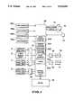
- FIG. 1is a block diagram of one embodiment of the present invention
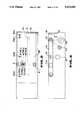
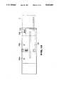
- FIG. 2is a plan view of a card conveyer passageway
- FIG. 3is a side view of the conveyer passageway
- FIGS. 4(a), (b)are plan views of the front and back faces, respectively, of a card
- FIG. 5illustrates data on the standard values of a quantity of conveyance to the punching position
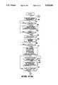
- FIG. 6is a flowchart indicative of the whole processing of a card
- FIGS. 7(a) and (b)are flowcharts indicative of the details of a punching operation
- FIGS. 8(a-i)is a timing chart indicative of the punching operation.
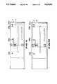
- FIGS. 9-13show the transition of the card state.
- a photosensor PS1senses the insertion of a card 1 into an insertion slot 2 and provided on the conveyance surface at a position closest to insertion slot 2.
- a photosensor PS2detects the length of the card 1 and is provided at a position slightly inward compared to photosensor PS1.
- a photosensor PS3senses whether the trailing end of card 1 has arrived at a predetermined position.
- a photosensor PS4senses whether card 1 has been conveyed to a stop position in the conveyance passageway, and is provided at a position shown in FIG. 2.
- a read head 3reads a barcode recorded on a longitudinal side of card 1 on its back as shown in FIG. 4(b).
- Barcode 4includes the name of a company which issued the card, for example.
- a punch sensing head 5magnetically senses a punch hole 6 formed in card 1.
- Card 1has a total of 15 punch positions as shown in FIG. 4(a) which shows the front side of the card.
- a punch holeis formed at a position shown by one of "1"-"15" in accordance with a sum of money corresponding to the use of card 1.
- FIG. 4(b)which shows the back of card 1
- a data read head 7reads data recorded in magnetic recording section 8 formed on the back of card 1.
- Magnetic recording section 8is composed of a total of three tracks TR1-TR3 and hence data read head 7 is for the three tracks.
- There are in magnetic recording section 8records such as data on the sum of money corresponding to the use of the card.
- Data write head 9records data on a sum of money corresponding to the use of the card into magnetic recording section 8.
- read and write heads 7 and 9are shown by 7(TR1)-7(TR3) and 9(TR1)-9(TR3) corresponding to the tracks.
- Motor 10is a source of power to carry card 1, and includes a reversible DC motor, for example.
- Rotary encoder 11rotates synchronously with motor 10 and generates pulses corresponding in number to the quantity of rotation of the motor. As shown in FIG. 3, the rotational shaft of motor 10 is coupled to pinch roller 12 the rotation of which is transmitted to conveyer belt 13 to thereby drive the belt in the direction of arrow and hence carry card 1 on the belt.
- Rotary encoder 11is coupled to the rotational shaft of pinch roller 12 to generated pulses corresponding in number to a quantity of motor rotation or a quantity of card conveyance by conveyer belt 13.
- switching circuit 14switches the direction of motor rotation by changing the polarity of a voltage applied across motor 10.
- Shutter solenoid 15actuates shutter 16 provided at card insertion slot 2 as shown in FIGS. 2 and 3.
- Shutter 16is open before card insertion and closed immediately after card insertion, reopened after a series of processes including the punching operation has been completed and then returns card 1.
- Punching solenoid 17forms a punched hole 6 and is driven when the target position of a hole in the card coincides with punching pin 18 (FIG. 3).
- the position of punching pin 18is shown by PP in FIG. 2.
- Control unit 23controls the read/write of data on the sum of money corresponding to the use of the card recorded in magnetic recording section 8, and the punching operation. In order to control the punching operation, control unit 23 includes stop position counter 230, length counter 231, punching position counter 232, coast counter 233, and timer 234.
- Memory (EEROM) 24beforehand stores programs necessary for reading and writing data on the sum of money corresponding to the use of card 1 and constants which are standard value data TRD1-TRD15 which determine quantities of conveyance to punch holes "1"-"15" from the position of the card trailing end sensed by photosensor PS3 and data on target quantities of conveyance P1-P15 to convey card 1 with the respective punch positions as targets.
- TRD1-TRD15standard value data
- FIG. 6is a flowchart indicative of the whole operation of the card puncher covering the card insertion to the card return. If the power source is turned on, central control unit 23 makes an initial diagnosis of whether there are any abnormalities in the elements of the puncher (step 30). Thereafter, if card 1 is inserted and a detection signal indicative of this fact is inputted by photosensor PS1 into central control unit 23 (step 31), the control unit drives motor 10 forwardly. Thus, card 1 is carried by rotation of conveyer belt 13, and the position of the card changes sequentially in the order of the state of FIG. 9--the state of FIG. 10--the state of FIG. 11--the state of FIG. 12.
- central control unit 23causes read head 7 to read data recorded in magnetic recording section 8 from when photosensor PS1 is turned off (or senses no cards). If the leading end of card 1 is sensed by photosensor PS4, central control unit 23 causes stop position counter 230 to count pulses output by rotary encoder 11 since photosensor PS4 was turned on in order to stop card 1 at the stop position shown in FIG. 12. If the count arrives at a value corresponding to the stop position, motor 10 is stopped.
- step 32Barcode 4 recorded on a longitudinal side of card 1 is also read by barcode read head 3, and the read data is input to central control unit 23 and temporarily stored in memory 24.
- Central control unit 23determines a sum of money corresponding to the use of card 1 in accordance with the read data. If the sum of money is insufficient or if the read card is of a different type, a return command is issued to thereby reverse motor 10 and card 1 is then returned out of insertion slot 2 (step 33, 41). If the card is not to be returned, a shift is made to step 34 directed to data writing to update data on the remaining sum of money in magnetic recording section 8.
- central control unit 23reverses motor 10 to return card 1 from the stop position of FIG. 12 to the initial position of FIG. 9, and then drive motor 10 forwardly for conveying purposes.
- data on the remaining sum of money in the recording section 8is updated by write head 9. If there are any conditions for returning card 1, for example, since there is no need for punching the card after the data writing, motor 10 is reversed to return card 1 (step 35).
- central control unit 23If updating data on the remaining sum of money is completed, central control unit 23 returns card 1 from the stop position of FIG. 12 to the initial position of FIG. 9 to shift to the punching process (step 36). Thereafter, it drives motor 10 forwardly, to convey card 1 again toward the stop position of FIG. 12. If the card arrives at the stop position, motor 10 is reversed to carry card 1 toward insertion slot 2. Central control unit 23 actuates punching solenoid 17 in the course of card returning to its initial position of FIG. 9 to punch the card at the position of one of the numbers "1"-"15" corresponding to the remaining sum of money. If a punched hole 6 is formed, it is checked whether the hole is formed normally or not (step 37). In the hole checking process, card 1 is conveyed from its initial position of FIG.
- step 38card 1 is returned to its initial position of FIG. 9, and the punching operation at step 36 is executed again. If the punching check is ended, motor 10 is reversed to return card 1 out of insertion slot 2, as shown in FIG. 13. If conditions, for example, of an illegal use of the card are found, a take-in command is issued to take card 1 into the puncher (step 40).
- card 1goes and returns once at each of steps 32, 34, 36 and 37, and hence completes a series of processes by going and returning four times in all.
- Shutter 16is closed by shutter solenoid 15 to thereby inhibit the insertion of the next card until the series of processes are completed.
- central control unit 23When central control unit 23 reads data at step 32, it causes length counter 231 to count output pulses from rotary encoder 11 produced from when photosensor PS2 is turned on to when it is turned off. It determines whether the length of card 1 is normal or not in accordance with the count value.
- Punched hole 6is formed in the course of card conveyance from the card stop position of FIG. 12 to the initial card position of FIG. 9.
- central control unit 23drives motor 10 forwardly via switching circuit 14 to convey card 1 from its initial position to its stop position (step 50).
- central control unit 23causes stop position counter 230 to count output pulses from rotary encoder 11 when the output of photosensor PS4 is turned on. If the count arrives at a value corresponding to the stop position, the central control unit stops motor 10 (steps 51-54). Thereafter, central control unit 23 reverses motor 10 via switching circuit 14 to convey card 1 toward card insertion slot 12 (step 55).
- FIG. 8(f)shows setting of data Pi on the target quantity of card conveyance.
- FIGS. 8(a)-(d)show the output signals from photosensors PS1-PS4; FIG. 8(e), the rotational state of the motor; FIG. 8(g), the count in the coast counter 233; FIG. 8(h), output pulses from rotary encoder 11; and FIG. 8(i), a drive signal for punching solenoid 17.
- Central control unit 23subtracts by "1" data Pi on the target quantity of conveyance in punching position counter 232 each time rotary encoder 11 generates a single pulse (steps 58, 59). By this decrement, output pulses from the encoder equal in number to Pi are generated to stop motor 10 if Pi in counter 232 arrives at "0" (steps 60, 61). Thereafter, coast counter 233 is cleared, a timer value of 50 ms is set in timer 234 to monitor the quantity of coast and the timer is then started (steps 62, 63).
- Motor 10rotates for a predetermined time due to its inertia and the inertia of conveyer belt 13 even if a stop command is input thereto. Therefore, card 1 also coasts.
- Central control unit 23determines that the card is coasting if even a single pulse is generated from the encoder within the timer time of 50 ms to thereby cause counter 233 to count output pulses from the encoder during the coasting (steps 64, 65).
- the count in counter 233sequentially increases as shown in FIG. 8(g).
- the control unitdrives punching solenoid 17 for a time of 120 ms to cause a punched hole to be formed at the target position (steps 69-71).
- the error between Xi and TRDiis out of the allowable limit, it is checked whether Xi>TRDi or not. If Xi ⁇ TRDi, it is determined that card 1 has not arrived at its target position. Therefore, "Pi+(TRDi-Xi)" is calculated and the result is employed as a new quantity of conveyance Pi, namely, the target quantity of conveyance Pi is increased by a quantity corresponding to the error.
- FIG. 8illustrates by broken lines the drive timing of the solenoid when card 1 is conveyed to its normal or correct position.
- the cardis again positioned in accordance with data Pi on the corrected quantity of conveyance, so that high accuracy positioning is achieved without using a clutch or a brake and the whole mechanism is reduced in size. Since card 1 is conveyed at high speed, the punching time is small even if repositioning is tried.
- card 1 having magnetic recording section 8has been described as an example, the present invention may be applicable to various card-like mediums such as pieces of paper, admission tickets and other tickets.
- While the reference point from which the actual amount of conveyance to the punching position is measuredis set at the position of photosensor PS3, it may be set at the position of photosensor PS4. It should be noted that since PS3 is closer to the punching pin than PS4, setting the reference point at the photosensor PS3 provides higher positioning accuracy.
Landscapes
- Physics & Mathematics (AREA)
- Engineering & Computer Science (AREA)
- General Physics & Mathematics (AREA)
- Theoretical Computer Science (AREA)
- Business, Economics & Management (AREA)
- Accounting & Taxation (AREA)
- Strategic Management (AREA)
- General Business, Economics & Management (AREA)
- Computer Networks & Wireless Communication (AREA)
- Microelectronics & Electronic Packaging (AREA)
- Conveying Record Carriers (AREA)
- Perforating, Stamping-Out Or Severing By Means Other Than Cutting (AREA)
- Devices For Checking Fares Or Tickets At Control Points (AREA)
- Credit Cards Or The Like (AREA)
- Control Of Vending Devices And Auxiliary Devices For Vending Devices (AREA)
Abstract
Description
Claims (15)
Applications Claiming Priority (1)
| Application Number | Priority Date | Filing Date | Title |
|---|---|---|---|
| JP63301822AJPH02148189A (en) | 1988-11-29 | 1988-11-29 | Card punching device |
Publications (1)
| Publication Number | Publication Date |
|---|---|
| US5019695Atrue US5019695A (en) | 1991-05-28 |
Family
ID=17901582
Family Applications (1)
| Application Number | Title | Priority Date | Filing Date |
|---|---|---|---|
| US07/437,367Expired - LifetimeUS5019695A (en) | 1988-11-29 | 1989-11-15 | Puncher and method of controlling the puncher |
Country Status (8)
| Country | Link |
|---|---|
| US (1) | US5019695A (en) |
| EP (1) | EP0372770B1 (en) |
| JP (1) | JPH02148189A (en) |
| KR (1) | KR930000689B1 (en) |
| AU (1) | AU620172B2 (en) |
| CA (1) | CA2004089C (en) |
| DE (1) | DE68915129T2 (en) |
| ES (1) | ES2052934T3 (en) |
Cited By (21)
| Publication number | Priority date | Publication date | Assignee | Title |
|---|---|---|---|---|
| US5424522A (en)* | 1993-06-25 | 1995-06-13 | Tamura Electric Works, Ltd. | Card convey device and method therefor |
| US20040054581A1 (en)* | 2002-09-13 | 2004-03-18 | Visa U.S.A. | Network centric loyalty system |
| US20040054591A1 (en)* | 2002-09-13 | 2004-03-18 | Visa U.S.A., Inc. | Opt-in/opt-out in loyalty system |
| US20040148224A1 (en)* | 2002-09-13 | 2004-07-29 | Visa U.S.A. | Method and apparatus for electronic support and delivery of multiple lottery and sweepstake programs, in substantially off-line environments |
| US20040153715A1 (en)* | 2002-09-13 | 2004-08-05 | Visa U.S.A., Inc. | Method and system for managing token image replacement |
| US20050045718A1 (en)* | 2003-09-03 | 2005-03-03 | Visa U.S.A., Inc. | Method, system and portable consumer device using wildcard values |
| US20050058427A1 (en)* | 2003-09-12 | 2005-03-17 | Visa U.S.A. Inc. | Method and system for providing interactive cardholder rewards image replacement |
| US20050071226A1 (en)* | 2003-09-30 | 2005-03-31 | Visa U.S.A. Inc. | Method and system for managing dynamic terms and conditions and user interaction |
| US20050071235A1 (en)* | 2003-09-30 | 2005-03-31 | Visa U.S.A Inc. | Method and system for providing a distributed adaptive rules based dynamic pricing system |
| US6920611B1 (en) | 2002-11-25 | 2005-07-19 | Visa U.S.A., Inc. | Method and system for implementing a loyalty merchant component |
| US6964695B2 (en) | 2001-03-13 | 2005-11-15 | Carbon Technologies Nv | Method and equipment for removing volatile compounds from air |
| US20060179007A1 (en)* | 2003-11-06 | 2006-08-10 | Visa U.S.A. | Centralized electronic commerce card transactions |
| US20080243623A1 (en)* | 2002-09-13 | 2008-10-02 | Liane Redford | Method and system for managing limited use coupon and coupon prioritization |
| US7725369B2 (en) | 2003-05-02 | 2010-05-25 | Visa U.S.A. Inc. | Method and server for management of electronic receipts |
| US8010405B1 (en) | 2002-07-26 | 2011-08-30 | Visa Usa Inc. | Multi-application smart card device software solution for smart cardholder reward selection and redemption |
| US20130057853A1 (en)* | 2011-08-31 | 2013-03-07 | Claudio Garcia Rubio | Photoelectric meter for stamps perforations |
| US8407083B2 (en) | 2003-09-30 | 2013-03-26 | Visa U.S.A., Inc. | Method and system for managing reward reversal after posting |
| US8429048B2 (en) | 2009-12-28 | 2013-04-23 | Visa International Service Association | System and method for processing payment transaction receipts |
| US8489452B1 (en) | 2003-09-10 | 2013-07-16 | Target Brands, Inc. | Systems and methods for providing a user incentive program using smart card technology |
| US8554610B1 (en) | 2003-08-29 | 2013-10-08 | Visa U.S.A. Inc. | Method and system for providing reward status |
| US11132691B2 (en) | 2009-12-16 | 2021-09-28 | Visa International Service Association | Merchant alerts incorporating receipt data |
Families Citing this family (1)
| Publication number | Priority date | Publication date | Assignee | Title |
|---|---|---|---|---|
| DE102014204663A1 (en)* | 2014-03-13 | 2015-09-17 | Roth + Weber Gmbh | Apparatus for punching a staple and / or hole edge of a print medium |
Citations (11)
| Publication number | Priority date | Publication date | Assignee | Title |
|---|---|---|---|---|
| US3735093A (en)* | 1971-06-30 | 1973-05-22 | Ibm | Step motor and controls for non-oscillating punch/read positioning of 80-column record cards |
| US3818189A (en)* | 1972-08-01 | 1974-06-18 | Raymond Engineering | Data card reader |
| JPS541125A (en)* | 1978-03-06 | 1979-01-06 | Canon Kk | Printer |
| US4172552A (en)* | 1978-09-21 | 1979-10-30 | Case John M | Credit card processing system |
| JPS5758700A (en)* | 1980-09-27 | 1982-04-08 | Osaka Chem Lab | Adzuki saponins, their isolations and uses |
| US4331863A (en)* | 1980-10-29 | 1982-05-25 | Service Distributors, Inc. | Punch mechanism for machine actuator cards |
| JPS5975367A (en)* | 1982-10-20 | 1984-04-28 | Fanuc Ltd | Puncher control device |
| JPS6131908A (en)* | 1984-07-25 | 1986-02-14 | Hashiba Tekko Kk | Measuring instrument for tip diameter of cutter for engraving |
| JPS6168771A (en)* | 1984-09-11 | 1986-04-09 | Omron Tateisi Electronics Co | Card processor |
| JPS6168770A (en)* | 1984-09-11 | 1986-04-09 | Omron Tateisi Electronics Co | Card processor |
| JPS61123056A (en)* | 1984-11-20 | 1986-06-10 | Shinko Electric Co Ltd | Read/write device for magnetic card |
Family Cites Families (7)
| Publication number | Priority date | Publication date | Assignee | Title |
|---|---|---|---|---|
| US3716698A (en)* | 1971-09-02 | 1973-02-13 | Gen Res Inc | Control and recording apparatus |
| FR2219729A5 (en)* | 1973-02-23 | 1974-09-20 | Crouzet Sa | |
| US3940127A (en)* | 1974-04-08 | 1976-02-24 | Decision Data Computer Corporation | Programmably alterable incrementing system |
| WO1981003562A1 (en)* | 1980-06-03 | 1981-12-10 | K Payne | Debit card system |
| US4370550A (en)* | 1980-10-29 | 1983-01-25 | Service Distributors, Inc. | Dual read-record head for magnetic card machine actuator |
| EP0051403A3 (en)* | 1980-10-29 | 1982-10-13 | Service Distributors, Inc. | Card punch |
| FR2597229B1 (en)* | 1986-04-11 | 1991-01-11 | Flonic Sa | ELECTRONIC MEMORY CARD PROCESSING DEVICE FOR PROVIDING BENEFITS |
- 1988
- 1988-11-29JPJP63301822Apatent/JPH02148189A/enactiveGranted
- 1989
- 1989-11-15USUS07/437,367patent/US5019695A/ennot_activeExpired - Lifetime
- 1989-11-16AUAU44748/89Apatent/AU620172B2/ennot_activeCeased
- 1989-11-17KRKR1019890016662Apatent/KR930000689B1/ennot_activeExpired - Lifetime
- 1989-11-24DEDE68915129Tpatent/DE68915129T2/ennot_activeExpired - Fee Related
- 1989-11-24ESES89312247Tpatent/ES2052934T3/ennot_activeExpired - Lifetime
- 1989-11-24EPEP89312247Apatent/EP0372770B1/ennot_activeExpired - Lifetime
- 1989-11-28CACA002004089Apatent/CA2004089C/ennot_activeExpired - Fee Related
Patent Citations (11)
| Publication number | Priority date | Publication date | Assignee | Title |
|---|---|---|---|---|
| US3735093A (en)* | 1971-06-30 | 1973-05-22 | Ibm | Step motor and controls for non-oscillating punch/read positioning of 80-column record cards |
| US3818189A (en)* | 1972-08-01 | 1974-06-18 | Raymond Engineering | Data card reader |
| JPS541125A (en)* | 1978-03-06 | 1979-01-06 | Canon Kk | Printer |
| US4172552A (en)* | 1978-09-21 | 1979-10-30 | Case John M | Credit card processing system |
| JPS5758700A (en)* | 1980-09-27 | 1982-04-08 | Osaka Chem Lab | Adzuki saponins, their isolations and uses |
| US4331863A (en)* | 1980-10-29 | 1982-05-25 | Service Distributors, Inc. | Punch mechanism for machine actuator cards |
| JPS5975367A (en)* | 1982-10-20 | 1984-04-28 | Fanuc Ltd | Puncher control device |
| JPS6131908A (en)* | 1984-07-25 | 1986-02-14 | Hashiba Tekko Kk | Measuring instrument for tip diameter of cutter for engraving |
| JPS6168771A (en)* | 1984-09-11 | 1986-04-09 | Omron Tateisi Electronics Co | Card processor |
| JPS6168770A (en)* | 1984-09-11 | 1986-04-09 | Omron Tateisi Electronics Co | Card processor |
| JPS61123056A (en)* | 1984-11-20 | 1986-06-10 | Shinko Electric Co Ltd | Read/write device for magnetic card |
Cited By (70)
| Publication number | Priority date | Publication date | Assignee | Title |
|---|---|---|---|---|
| US5424522A (en)* | 1993-06-25 | 1995-06-13 | Tamura Electric Works, Ltd. | Card convey device and method therefor |
| US6964695B2 (en) | 2001-03-13 | 2005-11-15 | Carbon Technologies Nv | Method and equipment for removing volatile compounds from air |
| US8010405B1 (en) | 2002-07-26 | 2011-08-30 | Visa Usa Inc. | Multi-application smart card device software solution for smart cardholder reward selection and redemption |
| US8775241B2 (en) | 2002-07-26 | 2014-07-08 | Visa U.S.A. Inc. | Method and system for determining rewards |
| US10460338B2 (en) | 2002-09-13 | 2019-10-29 | Visa U.S.A. Inc. | Network centric loyalty system |
| US20040054591A1 (en)* | 2002-09-13 | 2004-03-18 | Visa U.S.A., Inc. | Opt-in/opt-out in loyalty system |
| US9852437B2 (en) | 2002-09-13 | 2017-12-26 | Visa U.S.A. Inc. | Opt-in/opt-out in loyalty system |
| US7624917B2 (en) | 2002-09-13 | 2009-12-01 | Visa U.S.A. Inc. | Method and system for managing token image replacement |
| US7861919B2 (en) | 2002-09-13 | 2011-01-04 | Visa U.S.A. Inc. | Method and system for managing loyalty program information on a phone |
| US20040054581A1 (en)* | 2002-09-13 | 2004-03-18 | Visa U.S.A. | Network centric loyalty system |
| US20040153715A1 (en)* | 2002-09-13 | 2004-08-05 | Visa U.S.A., Inc. | Method and system for managing token image replacement |
| US20040148224A1 (en)* | 2002-09-13 | 2004-07-29 | Visa U.S.A. | Method and apparatus for electronic support and delivery of multiple lottery and sweepstake programs, in substantially off-line environments |
| US8682716B2 (en) | 2002-09-13 | 2014-03-25 | Visa U.S.A. Inc. | Method and system for managing limited use coupon and coupon prioritization |
| US8626577B2 (en) | 2002-09-13 | 2014-01-07 | Visa U.S.A | Network centric loyalty system |
| US7121456B2 (en) | 2002-09-13 | 2006-10-17 | Visa U.S.A. Inc. | Method and system for managing token image replacement |
| US7591412B2 (en) | 2002-09-13 | 2009-09-22 | Visa U.S.A. Inc. | Method and system for managing token image replacement |
| US20080243623A1 (en)* | 2002-09-13 | 2008-10-02 | Liane Redford | Method and system for managing limited use coupon and coupon prioritization |
| US20080128485A1 (en)* | 2002-09-13 | 2008-06-05 | Paul Spaeth | Method and system for managing token image replacement |
| US20080128484A1 (en)* | 2002-09-13 | 2008-06-05 | Paul Spaeth | Method and system for managing token image replacement |
| US8239261B2 (en) | 2002-09-13 | 2012-08-07 | Liane Redford | Method and system for managing limited use coupon and coupon prioritization |
| US8015060B2 (en) | 2002-09-13 | 2011-09-06 | Visa Usa, Inc. | Method and system for managing limited use coupon and coupon prioritization |
| US7374078B2 (en) | 2002-09-13 | 2008-05-20 | Visa U.S.A. Inc. | Method and system for managing token image replacement |
| US6920611B1 (en) | 2002-11-25 | 2005-07-19 | Visa U.S.A., Inc. | Method and system for implementing a loyalty merchant component |
| US8386343B2 (en) | 2003-05-02 | 2013-02-26 | Visa U.S.A. Inc. | Method and user device for management of electronic receipts |
| US8346634B2 (en) | 2003-05-02 | 2013-01-01 | Visa U.S.A. Inc. | Method and apparatus for management of electronic receipts on portable devices |
| US7725369B2 (en) | 2003-05-02 | 2010-05-25 | Visa U.S.A. Inc. | Method and server for management of electronic receipts |
| US7987120B2 (en) | 2003-05-02 | 2011-07-26 | Visa U.S.A. Inc. | Method and portable device for management of electronic receipts |
| US20110016007A1 (en)* | 2003-05-02 | 2011-01-20 | Nicholas Shiftan | Method and apparatus for management of electronic receipts on portable devices |
| US9087426B2 (en) | 2003-05-02 | 2015-07-21 | Visa U.S.A. Inc. | Method and administration system for management of electronic receipts |
| US7827077B2 (en) | 2003-05-02 | 2010-11-02 | Visa U.S.A. Inc. | Method and apparatus for management of electronic receipts on portable devices |
| US8554610B1 (en) | 2003-08-29 | 2013-10-08 | Visa U.S.A. Inc. | Method and system for providing reward status |
| US8793156B2 (en) | 2003-08-29 | 2014-07-29 | Visa U.S.A. Inc. | Method and system for providing reward status |
| US20070057051A1 (en)* | 2003-09-03 | 2007-03-15 | Visa U.S.A., Inc. | Method, system and portable consumer device using wildcard values |
| US7611054B2 (en) | 2003-09-03 | 2009-11-03 | Visa U.S.A. Inc. | Mobile phone including wildcard data string |
| US8141777B2 (en) | 2003-09-03 | 2012-03-27 | Visa U.S.A. Inc. | Method and system using wildcard values |
| US20100174597A1 (en)* | 2003-09-03 | 2010-07-08 | Visa U.S.A., Inc. | Method and system using wildcard values |
| US20050045718A1 (en)* | 2003-09-03 | 2005-03-03 | Visa U.S.A., Inc. | Method, system and portable consumer device using wildcard values |
| US7367501B2 (en) | 2003-09-03 | 2008-05-06 | Visa U.S.A. Inc. | Method, system and portable consumer device using wildcard values |
| US7104446B2 (en) | 2003-09-03 | 2006-09-12 | Visa U.S.A., Inc. | Method, system and portable consumer device using wildcard values |
| US7350702B2 (en) | 2003-09-03 | 2008-04-01 | Visa U.S.A. Inc. | Method, system and portable consumer device using wildcard values |
| US20080121698A1 (en)* | 2003-09-03 | 2008-05-29 | Visa U.S.A., Inc. | Method, system and portable consumer device using wildcard values |
| US7900831B2 (en) | 2003-09-03 | 2011-03-08 | Visa U.S.A. Inc. | Method and system using wildcard values |
| US7654451B2 (en) | 2003-09-03 | 2010-02-02 | Visa U.S.A. Inc. | Method, system and portable consumer device using wildcard values |
| US20110191155A1 (en)* | 2003-09-03 | 2011-08-04 | Visa U.S.A. Inc. | Method and system using wildcard values |
| US20070012764A1 (en)* | 2003-09-03 | 2007-01-18 | Visa U.S.A., Inc. | Method, system and portable consumer device using wildcard values |
| US8489452B1 (en) | 2003-09-10 | 2013-07-16 | Target Brands, Inc. | Systems and methods for providing a user incentive program using smart card technology |
| US9152973B2 (en) | 2003-09-10 | 2015-10-06 | Target Brands, Inc. | Systems and methods for providing a user incentive program using circuit chip technology |
| US10482488B2 (en) | 2003-09-10 | 2019-11-19 | Target Brands, Inc. | Identifying and dispensing special offers based on current and/or past transactions |
| US7464870B2 (en) | 2003-09-12 | 2008-12-16 | Visa U.S.A. Inc. | Method and system for providing interactive cardholder rewards image replacement |
| US7051923B2 (en) | 2003-09-12 | 2006-05-30 | Visa U.S.A., Inc. | Method and system for providing interactive cardholder rewards image replacement |
| US20080097852A1 (en)* | 2003-09-12 | 2008-04-24 | Loc Nguyen | Method and system for providing interactive cardholder rewards image replacement |
| US20050058427A1 (en)* | 2003-09-12 | 2005-03-17 | Visa U.S.A. Inc. | Method and system for providing interactive cardholder rewards image replacement |
| US7857215B2 (en) | 2003-09-12 | 2010-12-28 | Visa U.S.A. Inc. | Method and system including phone with rewards image |
| US20090159675A1 (en)* | 2003-09-12 | 2009-06-25 | Loc Nguyen | Method and system for providing interactive cardholder rewards image replacement |
| US20070001000A1 (en)* | 2003-09-12 | 2007-01-04 | Visa U.S.A. Inc. | Method and system for providing interactive cardholder rewards image replacement |
| US7857216B2 (en) | 2003-09-12 | 2010-12-28 | Visa U.S.A. Inc. | Method and system for providing interactive cardholder rewards image replacement |
| US8005763B2 (en) | 2003-09-30 | 2011-08-23 | Visa U.S.A. Inc. | Method and system for providing a distributed adaptive rules based dynamic pricing system |
| US8407083B2 (en) | 2003-09-30 | 2013-03-26 | Visa U.S.A., Inc. | Method and system for managing reward reversal after posting |
| US20050071226A1 (en)* | 2003-09-30 | 2005-03-31 | Visa U.S.A. Inc. | Method and system for managing dynamic terms and conditions and user interaction |
| US8244648B2 (en) | 2003-09-30 | 2012-08-14 | Visa U.S.A. Inc. | Method and system for providing a distributed adaptive rules based dynamic pricing system |
| US20050071235A1 (en)* | 2003-09-30 | 2005-03-31 | Visa U.S.A Inc. | Method and system for providing a distributed adaptive rules based dynamic pricing system |
| US20060179007A1 (en)* | 2003-11-06 | 2006-08-10 | Visa U.S.A. | Centralized electronic commerce card transactions |
| US9710811B2 (en) | 2003-11-06 | 2017-07-18 | Visa U.S.A. Inc. | Centralized electronic commerce card transactions |
| US7653602B2 (en) | 2003-11-06 | 2010-01-26 | Visa U.S.A. Inc. | Centralized electronic commerce card transactions |
| US20100023437A1 (en)* | 2003-11-06 | 2010-01-28 | Visa U.S.A. | Centralized Electronic Commerce Card Transactions |
| US11132691B2 (en) | 2009-12-16 | 2021-09-28 | Visa International Service Association | Merchant alerts incorporating receipt data |
| US8650124B2 (en) | 2009-12-28 | 2014-02-11 | Visa International Service Association | System and method for processing payment transaction receipts |
| US8429048B2 (en) | 2009-12-28 | 2013-04-23 | Visa International Service Association | System and method for processing payment transaction receipts |
| US8717554B2 (en)* | 2011-08-31 | 2014-05-06 | Claudio GARCIA RUBIO | Photoelectric meter for stamps perforations |
| US20130057853A1 (en)* | 2011-08-31 | 2013-03-07 | Claudio Garcia Rubio | Photoelectric meter for stamps perforations |
Also Published As
| Publication number | Publication date |
|---|---|
| EP0372770B1 (en) | 1994-05-04 |
| EP0372770A3 (en) | 1990-08-16 |
| JPH0567986B2 (en) | 1993-09-28 |
| ES2052934T3 (en) | 1994-07-16 |
| CA2004089C (en) | 1995-11-21 |
| AU4474889A (en) | 1990-06-07 |
| DE68915129D1 (en) | 1994-06-09 |
| DE68915129T2 (en) | 1994-10-20 |
| EP0372770A2 (en) | 1990-06-13 |
| AU620172B2 (en) | 1992-02-13 |
| JPH02148189A (en) | 1990-06-07 |
| CA2004089A1 (en) | 1990-05-29 |
| KR900008401A (en) | 1990-06-04 |
| KR930000689B1 (en) | 1993-01-29 |
Similar Documents
| Publication | Publication Date | Title |
|---|---|---|
| US5019695A (en) | Puncher and method of controlling the puncher | |
| US5046076A (en) | Credit card counter with phase error detecting and precount comparing verification system | |
| US5484993A (en) | Card reader maintenance system | |
| JPH087055A (en) | Magnetic card reader and writer | |
| US4995060A (en) | Card counter with card counting preset data entry system method | |
| JP2598945B2 (en) | Prepaid card device | |
| EP0434728B1 (en) | Card counter | |
| JP2994708B2 (en) | Stop position control device for card transporter | |
| JPS6220036Y2 (en) | ||
| KR880000236B1 (en) | A control method for turning papers over automatically | |
| JP2591017B2 (en) | Prepaid card transport control system | |
| JPH056232B2 (en) | ||
| JPH07272018A (en) | Recording medium position detecting device and recording medium position detecting method | |
| CN119895428A (en) | Card positioning method and card reader | |
| JP2784875B2 (en) | Card reader | |
| JPH04241080A (en) | Information card recording and reproducing device | |
| JPH04104381A (en) | Controller for punch hole punching position | |
| JP2900049B2 (en) | Card processing device with printing function | |
| KR19990002566U (en) | Magnetic ticket data recorder | |
| JPH10177625A (en) | Ic card reader and method for positioning stop of ic card | |
| JPH0690843B2 (en) | Automatic cassette feeder | |
| JPS59136276A (en) | Detector for print reference mark | |
| JPS61226889A (en) | Time recorder | |
| JPH0415737B2 (en) | ||
| JPH0457035B2 (en) |
Legal Events
| Date | Code | Title | Description |
|---|---|---|---|
| AS | Assignment | Owner name:KABUSHIKI KAISHA NIPPON CONLUX, JAPAN Free format text:ASSIGNMENT OF ASSIGNORS INTEREST.;ASSIGNOR:ITAKO, EIJI;REEL/FRAME:005177/0827 Effective date:19891102 | |
| STCF | Information on status: patent grant | Free format text:PATENTED CASE | |
| FEPP | Fee payment procedure | Free format text:PAYOR NUMBER ASSIGNED (ORIGINAL EVENT CODE: ASPN); ENTITY STATUS OF PATENT OWNER: LARGE ENTITY | |
| FPAY | Fee payment | Year of fee payment:4 | |
| FPAY | Fee payment | Year of fee payment:8 | |
| FPAY | Fee payment | Year of fee payment:12 | |
| AS | Assignment | Owner name:CITIBANK, N.A., TOKYO BRANCH, JAPAN Free format text:SECURITY AGREEMENT;ASSIGNOR:NIPPON CONLUX CO., LTD.;REEL/FRAME:017957/0752 Effective date:20060719 | |
| AS | Assignment | Owner name:AP6 CO., LTD., JAPAN Free format text:MERGER;ASSIGNOR:NIPPON CONLUX CO., LTD.;REEL/FRAME:018679/0741 Effective date:20060930 Owner name:NIPPON CONLUX CO., LTD., JAPAN Free format text:CHANGE OF NAME;ASSIGNOR:AP6 CO., LTD.;REEL/FRAME:018679/0787 Effective date:20060930 | |
| AS | Assignment | Owner name:CITIBANK JAPAN LTD., JAPAN Free format text:CHANGE OF SECURITY AGENT;ASSIGNOR:CITIBANK, N.A., TOKYO BUILDING;REEL/FRAME:019704/0952 Effective date:20070701 |