US5019121A - Helical fluid-actuated torsional motor - Google Patents
Helical fluid-actuated torsional motorDownload PDFInfo
- Publication number
- US5019121A US5019121AUS07/528,432US52843290AUS5019121AUS 5019121 AUS5019121 AUS 5019121AUS 52843290 AUS52843290 AUS 52843290AUS 5019121 AUS5019121 AUS 5019121A
- Authority
- US
- United States
- Prior art keywords
- bladder
- braid
- helix
- helical
- fluid
- Prior art date
- Legal status (The legal status is an assumption and is not a legal conclusion. Google has not performed a legal analysis and makes no representation as to the accuracy of the status listed.)
- Expired - Fee Related
Links
Images
Classifications
- A—HUMAN NECESSITIES
- A61—MEDICAL OR VETERINARY SCIENCE; HYGIENE
- A61B—DIAGNOSIS; SURGERY; IDENTIFICATION
- A61B1/00—Instruments for performing medical examinations of the interior of cavities or tubes of the body by visual or photographical inspection, e.g. endoscopes; Illuminating arrangements therefor
- A61B1/005—Flexible endoscopes
- A61B1/008—Articulations
- F—MECHANICAL ENGINEERING; LIGHTING; HEATING; WEAPONS; BLASTING
- F15—FLUID-PRESSURE ACTUATORS; HYDRAULICS OR PNEUMATICS IN GENERAL
- F15B—SYSTEMS ACTING BY MEANS OF FLUIDS IN GENERAL; FLUID-PRESSURE ACTUATORS, e.g. SERVOMOTORS; DETAILS OF FLUID-PRESSURE SYSTEMS, NOT OTHERWISE PROVIDED FOR
- F15B15/00—Fluid-actuated devices for displacing a member from one position to another; Gearing associated therewith
- F15B15/08—Characterised by the construction of the motor unit
- F15B15/10—Characterised by the construction of the motor unit the motor being of diaphragm type
- F15B15/103—Characterised by the construction of the motor unit the motor being of diaphragm type using inflatable bodies that contract when fluid pressure is applied, e.g. pneumatic artificial muscles or McKibben-type actuators
Definitions
- This inventionrelates to hydraulically or pneumatically actuated motors, and is more particularly directed to a torsional fluid-dynamic muscle which can be made of small diameter and incorporated into a steering or articulation section of a flexible elongated probe.
- the inventionis also directed to improvements in borescopes and/or endoscopes which permit four-way steering of the distal end of an insertion tube without reliance on the conventional, but delicate and trouble-prone cable-type steering movement.
- the torsional fluid-dynamic muscle or motor of this inventionhas other applications including rotary actuators and gauges, grabbers, and supports for remote tools.
- the inventioncan also be regarded as a pump for converting an angular or torsional force to a fluid pressure.
- Borescopes or similar flexible probesare generally configured as an elongated flexible insertion tube with a viewing head at its distal or forward end and a control housing for controlling or steering the distal or forward end.
- the typical borescopehas a bendable tubular steering section or articulation section at the distal end adjacent the viewing head.
- the steering sectioncomprises a series of alternating wobble washers and spacers, with control cables that extend through the wobble washers and then through the remainder of the flexible insertion tube.
- the steering cablesconnect with a steering control unit in the control section. Each such pair of cables is differentially displaced to bend the steering section.
- the viewing headcan be remotely oriented to facilitate inspection of an object.
- Borescopesare often required to bend in narrow, tortuous passageways, so the diameter of the borescope is often quite limited, e.g. 6 mm. Also, the pathway to the object or target can be quite long, which then requires the insertion tube and the steering cables to be rather long, e.g. fifteen meters or more.
- That patentdescribes a "muscle,” i.e. a linear traction motor, that addresses many of the problems found in these prior-art steering mechanisms.
- fluid dynamic muscles mounted adjacent the distal end of the insertion tubeare actuated by pneumatic or hydraulic pressure supplied through small flexible tubes within the borescope insertion tube.
- Short steering cablesconnect the respective muscles with the articulation mechanism. As fluid pressure is applied differentially to a pair of muscles, the cables move differentially and the articulation mechanism bends the steering section a desired amount.
- a hydraulic or pneumatic bending neckis proposed in copending and commonly-assigned U.S. patent application Ser. No. 538,232, filed June 18, 1990.
- an articulation or steering mechanismis formed of an elongated fluid-controlled muscle that has a flexible spine arranged in the axial direction along one side and disposed in the interface between the bladder and the braid.
- the braidconfines the bladder such that when the bladder is inflated, the bladder and braid expand laterally, but shorten axially. Because of the spine, the braid can shorten only on the side away from the spine, so the spine defines a bending plane for the bending neck.
- the spineis arcuately biased in one direction so that when no pressure is applied the bending neck is bent in one direction in the bending plane. At full pressure the bending neck is bent in the opposite direction, and at an intermediate pressure, the bending neck is held straight.
- This type of arrangementis capable of two-directional steering, i.e., bending that is confined to a single bending plane. It would be desirable to have four-way steering with fluid-dynamic bending, but as aforesaid, the bending neck is difficult to adapt for deflection in orthogonal directions.
- a helical biased torsional fluid dynamic muscle or motoris constructed which is suited to provide a rotational or torsional direction of steering to a bending section of a borescope or similar probe.
- the fluid dynamic musclehas an elongated tubular elastomeric bladder in the form of a helix, a tubular braid disposed over the bladder in the helix, and a resiliently flexible but substantially incompressible helical spine that is situated between the bladder and the braid on the inner side of the helix.
- the bladderis sealed at its ends and the braid is attached at one end to an anchor member and at the other end to a swivel member.
- a pressure inlet through one end of the bladderpermits fluid communication between a controlled fluid pressure source and the interior of the bladder. When pressure is applied, the fluid expands the bladder laterally, i.e., radially.
- the braidconstrains the bladder so that as it expands laterally, it shortens in its lengthwise, i.e. helical, direction.
- the spinerestrains helical motion on the inside of the helix, so the braid shortens on the outside of the helix. This serves to rotate the swivel member in one direction by an angle that depends on the amount of pressure applied to the muscle.
- the spineacts on the bladder and braid so that fluid is expelled from the bladder. This lengthens the bladder on the outside of the helix, and causes the muscle to rotate the swivel member in the opposite direction.
- the spinecan be in the form of a helical leaf or ribbon.
- the swivel membercan serve as a connector or mount on which a fluid dynamic bending neck is affixed.
- a signal and/or optical conduitcan pass axially through the system from a video or optical viewing head at the distal tip.
- the conduitcan be contained in a tubular core that passes from the swivel, proximally within the helix and out through a passage in the anchor member.
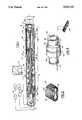
- FIG. 1is a schematic sectional view of an elongated flexible probe that incorporates a torsional fluid dynamic helical muscle or motor according to one embodiment of this invention.
- FIG. 2is an enlargement of a portion of FIG. 1.
- FIG. 3is an assembly view of a portion of the embodiment of FIG. 1.
- a flexible video probe 10has an elongated flexible insertion tube 11, of which only a distal portion is shown, an azimuthal steering section 12 situated at the distal end of the insertion tube, and a bending section 13 situated at the distal end of the azimuthal steering section 12.
- a video head 14At the distal end of the bending section 13 there is a video head 14.
- a conduit 15 that contains signal and control conductors and a fiber optic bundle for illuminationextends axially within the insertion tube 11 and through the sections 12 and 13 to connect the video head 14 with a video processor unit 16.
- the bending section 13is capable of two-way bending in a bending plane that is up to 60 to 90 degrees either side of a straight orientation.
- the bending neck 13is arranged as generally as described in the copending patent application Ser. No. 539,232 having a common assignee.
- a distal end piece 19 at the distal end of the bending section 13mounts the video viewing head 14.
- a passage 20extends axially through the proximal connector 17 and a passage 21 extends through the distal end piece 19; these passages 20, 21 carry the conduit 15.
- an elongated elastomeric bladder 22is coupled to the connector 17 and end piece 19, and a flexible but incompressible spine 23 is situated on one side of the bladder and extends between the connector 17 and the end piece 19.
- a braid 24 that is formed of right hand and left hand helically wound filamentsis disposed over the bladder 22 and spine 23 and is mechanically connected to the connector 17 and the end piece 19.
- the azimuthal steering section 12has a helical biased muscle or motor 25 that is driven to rotate in the azimuthal direction by controlled fluid pressure (either pneumatic or hydraulic).
- This muscle 25is formed of a helical elongated elastomeric bladder that is covered with a generally helical braid 20.
- the construction of the braid 27 and bladder 26can be generally as shown in FIG. 2.
- the helixshould have a suitable number of turns, and, although only about four turns are shown in FIG. 1, the helically biased muscle 25 could be configured of twelve or more turns.
- a proximal connector 29fits into the distal end of the insertion tube 11, while a distal end bushing 30 holds the swivel member 18 to permit rotation thereof.
- a sheath or skin 31 of a suitable materialcovers the azimuthal steering section 12 and extends between the connector 29 and the bushing 30.
- a tubular core 32extends proximally from a protuberance 33 on the swivel member 18 and passes within the helix of the muscle 25 and through a central passage 34 in the proximal connector 29 and then continues axially within the insertion tube 11.
- a controllable pressure source 35supplies pressurized fluid through the tubular core 32 to the interior of the bladder 22 of the bending section 13. The degree of arcuate bending of the section 13 depends on the pressure that is applied from this source 35.
- the proximal connector 29has a first annular region 36 in which there is cut a slot 37 to receive a proximal end of the helical muscle 25.
- the elongated braid 27 and bladder 26are folded over at the end and inserted into the slot 37. Then the slot is potted in epoxy or other potting compound.
- the region 36provides a surface from which the first turn of the helix starts.
- a second annular region 38receives the proximal end of the flexible sheath 31.
- a proximal-side protuberance 39fits into the distal end of the insertion tube 11.
- An axial fluid passage 40is bored through the connector 29 into the slot 37 in which the end of the helical muscle 25 is affixed. An opening is bored through this hole into the potting and the proximal end of the muscle 25 to provide fluid communication with the interior of the bladder 26.
- a fluid conduit 41extends proximally from the fluid passage 40 and extends within the insertion tube 11 to a controllable pressure source 42.
- the pressure source 42provides pneumatic or hydraulic pressure at a selected level to control a degree of rotation of the swivel 18 and thus the bending plane of the bending section 13. This degree of rotation should be arranged to be 180° or greater.
- the spine 28is on the inside of the spiral in the helical muscle 25.
- the bladderWhen pressure is applied from the source 42 to inflate the bladder 26, the bladder expands radially, i.e., laterally.
- the filaments of the braid 27constrain this expansion so that the braid 27 will tend to shorten i.e. in the direction of the helix.
- the spine 28prevents the inside of the muscle from contracting, so that the outside of the helix shortens differentially. Inflation tends to unwind the helical spine which, in this case, rotates the swivel 18 and the attached bending neck 13 in the direction of arrow A.
- the muscle 25relaxes and elongates helically on the outside, thereby allowing the spine to rewind, which rotates the swivel 18 and the bending neck 13 in the direction of arrow B.
- the bending neck 13should be capable of rotating 90° or more on either side of the zero position. This zero position occurs at a pressure approximately halfway between zero gauge pressure and the maximum allowable gauge pressure.
- a portable unitcan be constructed which is controlled by a small cylinder of compressed gas.
- the helical torsional motor 25is wound as a right-hand helix, but in other embodiments, the motor could be configured as a left-hand helix.
- the left hand configurationwould produce rotation in the direction of arrow B during inflation and rotation in the direction of arrow A when pressure is relieved.
- a pair of oppositely wound helicescould be employed, and differentially controlled for precise azimuthal steering.
- the spinecan be outside the braid, and bonded to it at the ends and one or more intermediate points.
- a rotational sealcan be employed between the swivel 18 and the bushing 30. This permits the insertion tube 11 to serve as a conduit for air between the controlled pressure source 42 and the azimuthal steering section 12. In that case, the fluid conduit 41 could be eliminated or could terminate a short distance proximally of the connector 29.
Landscapes
- Health & Medical Sciences (AREA)
- Engineering & Computer Science (AREA)
- Life Sciences & Earth Sciences (AREA)
- Surgery (AREA)
- Physics & Mathematics (AREA)
- Optics & Photonics (AREA)
- Biomedical Technology (AREA)
- Mechanical Engineering (AREA)
- Rehabilitation Therapy (AREA)
- Fluid Mechanics (AREA)
- Biophysics (AREA)
- Nuclear Medicine, Radiotherapy & Molecular Imaging (AREA)
- Chemical & Material Sciences (AREA)
- Pathology (AREA)
- Radiology & Medical Imaging (AREA)
- Analytical Chemistry (AREA)
- General Engineering & Computer Science (AREA)
- Heart & Thoracic Surgery (AREA)
- Medical Informatics (AREA)
- Molecular Biology (AREA)
- Animal Behavior & Ethology (AREA)
- General Health & Medical Sciences (AREA)
- Public Health (AREA)
- Veterinary Medicine (AREA)
- Instruments For Viewing The Inside Of Hollow Bodies (AREA)
- Endoscopes (AREA)
Abstract
Description
Claims (12)
Priority Applications (1)
| Application Number | Priority Date | Filing Date | Title |
|---|---|---|---|
| US07/528,432US5019121A (en) | 1990-05-25 | 1990-05-25 | Helical fluid-actuated torsional motor |
Applications Claiming Priority (1)
| Application Number | Priority Date | Filing Date | Title |
|---|---|---|---|
| US07/528,432US5019121A (en) | 1990-05-25 | 1990-05-25 | Helical fluid-actuated torsional motor |
Publications (1)
| Publication Number | Publication Date |
|---|---|
| US5019121Atrue US5019121A (en) | 1991-05-28 |
Family
ID=24105660
Family Applications (1)
| Application Number | Title | Priority Date | Filing Date |
|---|---|---|---|
| US07/528,432Expired - Fee RelatedUS5019121A (en) | 1990-05-25 | 1990-05-25 | Helical fluid-actuated torsional motor |
Country Status (1)
| Country | Link |
|---|---|
| US (1) | US5019121A (en) |
Cited By (67)
| Publication number | Priority date | Publication date | Assignee | Title |
|---|---|---|---|---|
| US5203319A (en)* | 1990-06-18 | 1993-04-20 | Welch Allyn, Inc. | Fluid controlled biased bending neck |
| US5350355A (en)* | 1992-02-14 | 1994-09-27 | Automated Medical Instruments, Inc. | Automated surgical instrument |
| US5626595A (en)* | 1992-02-14 | 1997-05-06 | Automated Medical Instruments, Inc. | Automated surgical instrument |
| WO1997022782A1 (en)* | 1995-12-21 | 1997-06-26 | Bruce Nappi | Actuators for simulating muscle activity in robotics |
| WO1999009879A1 (en)* | 1997-08-27 | 1999-03-04 | Pinotage, L.L.C. | Controllable multi-directional surgical positioning device |
| WO2001066959A1 (en)* | 2000-03-08 | 2001-09-13 | Festo Ag & Co. | Actuating device |
| US6375609B1 (en)* | 1992-11-25 | 2002-04-23 | Scimed Life Systems, Inc. | Micro-motor actuated therapeutic device |
| US20030194793A1 (en)* | 1997-03-31 | 2003-10-16 | Genentech, Inc. | Secreted and transmembrane polypeptides and nucleic acids encoding the same |
| US20040183900A1 (en)* | 2003-03-20 | 2004-09-23 | Everest Vit | Method and system for automatically detecting defects in remote video inspection applications |
| US20050129108A1 (en)* | 2003-01-29 | 2005-06-16 | Everest Vit, Inc. | Remote video inspection system |
| US20050168571A1 (en)* | 2004-01-29 | 2005-08-04 | Everest Vit, Inc. | Method and apparatus for improving the operation of a remote viewing device |
| US20060072903A1 (en)* | 2001-02-22 | 2006-04-06 | Everest Vit, Inc. | Method and system for storing calibration data within image files |
| EP1669018A1 (en)* | 2004-12-07 | 2006-06-14 | STM Medizintechnik Starnberg GmbH | Endoscope with rotatable distal endoscope head |
| US20060216173A1 (en)* | 2005-03-25 | 2006-09-28 | Arash Kheradvar | Helically actuated positive-displacement pump and method |
| US20070070340A1 (en)* | 2005-06-22 | 2007-03-29 | Karpen Thomas W | Remote video inspection system integrating audio communication functionality |
| US20070091183A1 (en)* | 2005-10-21 | 2007-04-26 | Ge Inspection Technologies, Lp | Method and apparatus for adapting the operation of a remote viewing device to correct optical misalignment |
| US20070156018A1 (en)* | 2005-06-24 | 2007-07-05 | Krauter Allan I | Insertion tube storage carousel |
| US20070156021A1 (en)* | 2005-09-14 | 2007-07-05 | Bradford Morse | Remote imaging apparatus having an adaptive lens |
| US20070167821A1 (en)* | 2005-11-30 | 2007-07-19 | Warren Lee | Rotatable transducer array for volumetric ultrasound |
| US20070165306A1 (en)* | 2002-01-25 | 2007-07-19 | Ge Inspection Technologies, Lp | Stereo-measurement borescope with 3-D viewing |
| US20070187574A1 (en)* | 2006-02-13 | 2007-08-16 | Ge Inspection Technologies, Lp | Electronic imaging device with photosensor arrays |
| US20070226258A1 (en)* | 2006-03-27 | 2007-09-27 | Thomas Eldred Lambdin | Article inspection apparatus |
| US20080021282A1 (en)* | 2004-02-09 | 2008-01-24 | Hoeg Hans D | Endoscope With Variable Direction of View Module |
| US20080151046A1 (en)* | 2006-12-22 | 2008-06-26 | Ge Inspection Technologies, Lp | Heat protection systems and methods for remote viewing devices |
| US20080158348A1 (en)* | 2006-12-29 | 2008-07-03 | General Electric Company | Inspection apparatus having illumination assembly |
| US20080157994A1 (en)* | 2006-12-29 | 2008-07-03 | General Electric Company | IP based voice communication enabled inspection system |
| US7422559B2 (en) | 2004-06-16 | 2008-09-09 | Ge Inspection Technologies, Lp | Borescope comprising fluid supply system |
| US20090005645A1 (en)* | 2005-05-04 | 2009-01-01 | Frassica James J | Rotate-to- advance catheterization system |
| US20090109045A1 (en)* | 2007-10-26 | 2009-04-30 | Delmonico James J | Battery and power management for industrial inspection handset |
| US20090109283A1 (en)* | 2007-10-26 | 2009-04-30 | Joshua Lynn Scott | Integrated storage for industrial inspection handset |
| US20090109429A1 (en)* | 2007-10-26 | 2009-04-30 | Joshua Lynn Scott | Inspection apparatus having heat sink assembly |
| US20090106948A1 (en)* | 2007-10-26 | 2009-04-30 | Lopez Joseph V | Method and apparatus for retaining elongated flexible articles including visual inspection apparatus inspection probes |
| US20100069718A1 (en)* | 2005-05-04 | 2010-03-18 | Frassica James J | Rotate-to-advance catheterization system |
| US20100076264A1 (en)* | 2005-05-04 | 2010-03-25 | Stephen Tallarida | Rotate-to-advance catheterization system |
| US20100081879A1 (en)* | 2005-05-04 | 2010-04-01 | Frassica James J | Rotate-to-advance catheterization system |
| US20100198876A1 (en)* | 2009-02-02 | 2010-08-05 | Honeywell International, Inc. | Apparatus and method of embedding meta-data in a captured image |
| US20100314443A1 (en)* | 2009-06-12 | 2010-12-16 | Hand Held Products, Inc. | Portable Data Terminal |
| US20110178370A1 (en)* | 1997-02-10 | 2011-07-21 | Frassica James J | Rotate to advance catheterization system |
| US8213676B2 (en) | 2006-12-20 | 2012-07-03 | Ge Inspection Technologies Lp | Inspection apparatus method and apparatus comprising motion responsive control |
| US8310604B2 (en) | 2007-10-26 | 2012-11-13 | GE Sensing & Inspection Technologies, LP | Visual inspection apparatus having light source bank |
| US8317678B2 (en) | 2005-05-04 | 2012-11-27 | Olympus Endo Technology America Inc. | Rotate-to-advance catheterization system |
| US8366674B2 (en) | 2005-05-04 | 2013-02-05 | Olympus Endo Technology America Inc. | Rotate-to-advance catheterization system |
| US8377041B2 (en) | 2005-02-28 | 2013-02-19 | Olympus Endo Technology America Inc. | Rotate-to-advance catheterization system |
| US8435229B2 (en) | 2006-02-28 | 2013-05-07 | Olympus Endo Technology America Inc. | Rotate-to-advance catheterization system |
| US8574220B2 (en) | 2006-02-28 | 2013-11-05 | Olympus Endo Technology America Inc. | Rotate-to-advance catheterization system |
| US20140066710A1 (en)* | 2012-06-19 | 2014-03-06 | University Of Iowa Research Foundation | Devices and methods for intraoperative control of endoscopic imaging |
| US8777841B2 (en) | 2007-05-18 | 2014-07-15 | Olympus Endo Technology America Inc. | Rotate-to-advance catheterization system |
| US8810636B2 (en) | 2006-12-20 | 2014-08-19 | Ge Inspection Technologies, Lp | Inspection apparatus method and apparatus comprising selective frame output |
| US9125655B2 (en) | 2010-07-16 | 2015-09-08 | California Institute Of Technology | Correction and optimization of wave reflection in blood vessels |
| US9220395B2 (en) | 1999-09-27 | 2015-12-29 | James J. Frassica | Rotate-to-advance catheterization system |
| US9656009B2 (en) | 2007-07-11 | 2017-05-23 | California Institute Of Technology | Cardiac assist system using helical arrangement of contractile bands and helically-twisting cardiac assist device |
| US10291850B2 (en) | 2006-12-20 | 2019-05-14 | General Electric Company | Inspection apparatus method and apparatus comprising selective frame output |
| CN111906811A (en)* | 2020-08-10 | 2020-11-10 | 安徽大学 | A fully flexible pneumatic actuator |
| US11122971B2 (en) | 2016-08-18 | 2021-09-21 | Neptune Medical Inc. | Device and method for enhanced visualization of the small intestine |
| US11135398B2 (en) | 2018-07-19 | 2021-10-05 | Neptune Medical Inc. | Dynamically rigidizing composite medical structures |
| US11219351B2 (en) | 2015-09-03 | 2022-01-11 | Neptune Medical Inc. | Device for endoscopic advancement through the small intestine |
| US11382491B2 (en)* | 2017-12-06 | 2022-07-12 | Olympus Corporation | Endoscope, distal end structure of endoscope and method for modifying distal end structure of endoscope |
| US11744443B2 (en) | 2020-03-30 | 2023-09-05 | Neptune Medical Inc. | Layered walls for rigidizing devices |
| US11793392B2 (en) | 2019-04-17 | 2023-10-24 | Neptune Medical Inc. | External working channels |
| US11937778B2 (en) | 2022-04-27 | 2024-03-26 | Neptune Medical Inc. | Apparatuses and methods for determining if an endoscope is contaminated |
| US12059128B2 (en) | 2018-05-31 | 2024-08-13 | Neptune Medical Inc. | Device and method for enhanced visualization of the small intestine |
| US12121677B2 (en) | 2021-01-29 | 2024-10-22 | Neptune Medical Inc. | Devices and methods to prevent inadvertent motion of dynamically rigidizing apparatuses |
| US20250052996A1 (en)* | 2023-08-08 | 2025-02-13 | Baker Hughes Holdings Llc | Automatic slap impact mitigation system |
| US12295550B2 (en) | 2017-07-20 | 2025-05-13 | Neptune Medical Inc. | Dynamically rigidizing overtube |
| WO2025115276A1 (en)* | 2023-12-01 | 2025-06-05 | 株式会社ブリヂストン | Hydraulic actuator |
| US12330292B2 (en) | 2023-09-28 | 2025-06-17 | Neptune Medical Inc. | Telescoping robot |
| US12329473B2 (en) | 2019-04-17 | 2025-06-17 | Neptune Medical Inc. | Dynamically rigidizing composite medical structures |
Citations (13)
| Publication number | Priority date | Publication date | Assignee | Title |
|---|---|---|---|---|
| US2386610A (en)* | 1943-10-30 | 1945-10-09 | Goodrich Co B F | Frictional mechanism |
| FR1022755A (en)* | 1950-08-02 | 1953-03-10 | Advanced pump connection | |
| SU144088A1 (en)* | 1960-07-06 | 1961-11-30 | С.Ф. Панько | Hydraulic Press |
| US3066853A (en)* | 1960-03-28 | 1962-12-04 | Walter Anderes | Bellows air pump |
| US3276477A (en)* | 1963-05-09 | 1966-10-04 | William J Bleasdale | Cushioning means for hydraulic system |
| US3315606A (en)* | 1964-12-24 | 1967-04-25 | Sinclair Research Inc | Pump apparatus |
| US3490733A (en)* | 1967-07-21 | 1970-01-20 | Commissariat Energie Atomique | Valve operating device |
| US3924519A (en)* | 1968-08-21 | 1975-12-09 | Goodrich Co B F | Actuator |
| US4108050A (en)* | 1974-08-14 | 1978-08-22 | Paynter Henry M | Fluid-driven torsional operators for turning rotary valves and the like |
| SU937801A1 (en)* | 1980-12-01 | 1982-06-23 | Предприятие П/Я Р-6543 | Positive displacement hydraulic machine |
| US4616556A (en)* | 1984-05-14 | 1986-10-14 | Anna Meilman | Flexible compressible piston |
| US4792173A (en)* | 1987-10-30 | 1988-12-20 | Duke University | Fluid actuated limb |
| US4794912A (en)* | 1987-08-17 | 1989-01-03 | Welch Allyn, Inc. | Borescope or endoscope with fluid dynamic muscle |
- 1990
- 1990-05-25USUS07/528,432patent/US5019121A/ennot_activeExpired - Fee Related
Patent Citations (13)
| Publication number | Priority date | Publication date | Assignee | Title |
|---|---|---|---|---|
| US2386610A (en)* | 1943-10-30 | 1945-10-09 | Goodrich Co B F | Frictional mechanism |
| FR1022755A (en)* | 1950-08-02 | 1953-03-10 | Advanced pump connection | |
| US3066853A (en)* | 1960-03-28 | 1962-12-04 | Walter Anderes | Bellows air pump |
| SU144088A1 (en)* | 1960-07-06 | 1961-11-30 | С.Ф. Панько | Hydraulic Press |
| US3276477A (en)* | 1963-05-09 | 1966-10-04 | William J Bleasdale | Cushioning means for hydraulic system |
| US3315606A (en)* | 1964-12-24 | 1967-04-25 | Sinclair Research Inc | Pump apparatus |
| US3490733A (en)* | 1967-07-21 | 1970-01-20 | Commissariat Energie Atomique | Valve operating device |
| US3924519A (en)* | 1968-08-21 | 1975-12-09 | Goodrich Co B F | Actuator |
| US4108050A (en)* | 1974-08-14 | 1978-08-22 | Paynter Henry M | Fluid-driven torsional operators for turning rotary valves and the like |
| SU937801A1 (en)* | 1980-12-01 | 1982-06-23 | Предприятие П/Я Р-6543 | Positive displacement hydraulic machine |
| US4616556A (en)* | 1984-05-14 | 1986-10-14 | Anna Meilman | Flexible compressible piston |
| US4794912A (en)* | 1987-08-17 | 1989-01-03 | Welch Allyn, Inc. | Borescope or endoscope with fluid dynamic muscle |
| US4792173A (en)* | 1987-10-30 | 1988-12-20 | Duke University | Fluid actuated limb |
Non-Patent Citations (1)
| Title |
|---|
| IBM Technical Disclosure Bulletin vol. 8, No. 6, 11/65, 1 Sheet.* |
Cited By (115)
| Publication number | Priority date | Publication date | Assignee | Title |
|---|---|---|---|---|
| US5203319A (en)* | 1990-06-18 | 1993-04-20 | Welch Allyn, Inc. | Fluid controlled biased bending neck |
| US5350355A (en)* | 1992-02-14 | 1994-09-27 | Automated Medical Instruments, Inc. | Automated surgical instrument |
| US5626595A (en)* | 1992-02-14 | 1997-05-06 | Automated Medical Instruments, Inc. | Automated surgical instrument |
| US5632758A (en)* | 1992-02-14 | 1997-05-27 | Automated Medical Instruments, Inc. | Automated surgical instrument |
| US6375609B1 (en)* | 1992-11-25 | 2002-04-23 | Scimed Life Systems, Inc. | Micro-motor actuated therapeutic device |
| WO1997022782A1 (en)* | 1995-12-21 | 1997-06-26 | Bruce Nappi | Actuators for simulating muscle activity in robotics |
| US5697285A (en)* | 1995-12-21 | 1997-12-16 | Nappi; Bruce | Actuators for simulating muscle activity in robotics |
| US20110178370A1 (en)* | 1997-02-10 | 2011-07-21 | Frassica James J | Rotate to advance catheterization system |
| US8764631B2 (en) | 1997-02-10 | 2014-07-01 | Olympus Endo Technology America Inc. | Rotate to advance catheterization system |
| US20030194793A1 (en)* | 1997-03-31 | 2003-10-16 | Genentech, Inc. | Secreted and transmembrane polypeptides and nucleic acids encoding the same |
| WO1999009879A1 (en)* | 1997-08-27 | 1999-03-04 | Pinotage, L.L.C. | Controllable multi-directional surgical positioning device |
| US6165123A (en)* | 1997-08-27 | 2000-12-26 | Pinotage Llc | Controllable multi-directional positioning system |
| US9220395B2 (en) | 1999-09-27 | 2015-12-29 | James J. Frassica | Rotate-to-advance catheterization system |
| US6840152B2 (en) | 2000-03-08 | 2005-01-11 | Festo Ag & Co. | Actuating means |
| US20030029312A1 (en)* | 2000-03-08 | 2003-02-13 | Ansgar Kriwet | Actuating device |
| WO2001066959A1 (en)* | 2000-03-08 | 2001-09-13 | Festo Ag & Co. | Actuating device |
| US20060072903A1 (en)* | 2001-02-22 | 2006-04-06 | Everest Vit, Inc. | Method and system for storing calibration data within image files |
| US20070165306A1 (en)* | 2002-01-25 | 2007-07-19 | Ge Inspection Technologies, Lp | Stereo-measurement borescope with 3-D viewing |
| US7564626B2 (en) | 2002-01-25 | 2009-07-21 | Ge Inspection Technologies Lp | Stereo-measurement borescope with 3-D viewing |
| US20080116093A1 (en)* | 2003-01-29 | 2008-05-22 | Ge Inspection Technologies Lp | Apparatus for storing an insertion tube |
| US20050129108A1 (en)* | 2003-01-29 | 2005-06-16 | Everest Vit, Inc. | Remote video inspection system |
| US20040183900A1 (en)* | 2003-03-20 | 2004-09-23 | Everest Vit | Method and system for automatically detecting defects in remote video inspection applications |
| US7134993B2 (en) | 2004-01-29 | 2006-11-14 | Ge Inspection Technologies, Lp | Method and apparatus for improving the operation of a remote viewing device by changing the calibration settings of its articulation servos |
| US20050168571A1 (en)* | 2004-01-29 | 2005-08-04 | Everest Vit, Inc. | Method and apparatus for improving the operation of a remote viewing device |
| US20080021282A1 (en)* | 2004-02-09 | 2008-01-24 | Hoeg Hans D | Endoscope With Variable Direction of View Module |
| US9591962B2 (en)* | 2004-02-09 | 2017-03-14 | Karl Storz Imaging, Inc. | Endoscope with variable direction of view module |
| US7422559B2 (en) | 2004-06-16 | 2008-09-09 | Ge Inspection Technologies, Lp | Borescope comprising fluid supply system |
| US7794390B2 (en) | 2004-12-07 | 2010-09-14 | Invendo Medical Gmbh | Endoscope having a rotatable distal endoscope head |
| EP1669018A1 (en)* | 2004-12-07 | 2006-06-14 | STM Medizintechnik Starnberg GmbH | Endoscope with rotatable distal endoscope head |
| US20060167342A1 (en)* | 2004-12-07 | 2006-07-27 | Konstantin Bob | Endoscope having a rotatable distal endoscope head |
| JP2006158971A (en)* | 2004-12-07 | 2006-06-22 | Stm Medizintechnik Starnberg Gmbh | Endoscope with rotatable terminal head |
| US8377041B2 (en) | 2005-02-28 | 2013-02-19 | Olympus Endo Technology America Inc. | Rotate-to-advance catheterization system |
| US7883325B2 (en)* | 2005-03-25 | 2011-02-08 | Arash Kheradvar | Helically actuated positive-displacement pump and method |
| US8794937B2 (en) | 2005-03-25 | 2014-08-05 | California Institute Of Technology | Helically actuated positive-displacement pump and method |
| US20060216173A1 (en)* | 2005-03-25 | 2006-09-28 | Arash Kheradvar | Helically actuated positive-displacement pump and method |
| US20100076264A1 (en)* | 2005-05-04 | 2010-03-25 | Stephen Tallarida | Rotate-to-advance catheterization system |
| US20100081879A1 (en)* | 2005-05-04 | 2010-04-01 | Frassica James J | Rotate-to-advance catheterization system |
| US20090005645A1 (en)* | 2005-05-04 | 2009-01-01 | Frassica James J | Rotate-to- advance catheterization system |
| US8317678B2 (en) | 2005-05-04 | 2012-11-27 | Olympus Endo Technology America Inc. | Rotate-to-advance catheterization system |
| US8747300B2 (en) | 2005-05-04 | 2014-06-10 | Olympus Endo Technology America Inc. | Rotate-to-advance catheterization system |
| US8343040B2 (en) | 2005-05-04 | 2013-01-01 | Olympus Endo Technology America Inc. | Rotate-to-advance catheterization system |
| US8235942B2 (en) | 2005-05-04 | 2012-08-07 | Olympus Endo Technology America Inc. | Rotate-to-advance catheterization system |
| US8366674B2 (en) | 2005-05-04 | 2013-02-05 | Olympus Endo Technology America Inc. | Rotate-to-advance catheterization system |
| US8414477B2 (en) | 2005-05-04 | 2013-04-09 | Olympus Endo Technology America Inc. | Rotate-to-advance catheterization system |
| US20100069718A1 (en)* | 2005-05-04 | 2010-03-18 | Frassica James J | Rotate-to-advance catheterization system |
| US20070070340A1 (en)* | 2005-06-22 | 2007-03-29 | Karpen Thomas W | Remote video inspection system integrating audio communication functionality |
| US7956888B2 (en) | 2005-06-22 | 2011-06-07 | Ge Inspection Technologies, Lp | Remote video inspection system integrating audio communication functionality |
| US20070156018A1 (en)* | 2005-06-24 | 2007-07-05 | Krauter Allan I | Insertion tube storage carousel |
| US7819798B2 (en) | 2005-06-24 | 2010-10-26 | Ge Inspection Technologies, Lp | Insertion tube storage carousel |
| US20070156021A1 (en)* | 2005-09-14 | 2007-07-05 | Bradford Morse | Remote imaging apparatus having an adaptive lens |
| US20070091183A1 (en)* | 2005-10-21 | 2007-04-26 | Ge Inspection Technologies, Lp | Method and apparatus for adapting the operation of a remote viewing device to correct optical misalignment |
| US20070167821A1 (en)* | 2005-11-30 | 2007-07-19 | Warren Lee | Rotatable transducer array for volumetric ultrasound |
| US7679041B2 (en) | 2006-02-13 | 2010-03-16 | Ge Inspection Technologies, Lp | Electronic imaging device with photosensor arrays |
| US20070187574A1 (en)* | 2006-02-13 | 2007-08-16 | Ge Inspection Technologies, Lp | Electronic imaging device with photosensor arrays |
| US8435229B2 (en) | 2006-02-28 | 2013-05-07 | Olympus Endo Technology America Inc. | Rotate-to-advance catheterization system |
| US8574220B2 (en) | 2006-02-28 | 2013-11-05 | Olympus Endo Technology America Inc. | Rotate-to-advance catheterization system |
| US20070225931A1 (en)* | 2006-03-27 | 2007-09-27 | Ge Inspection Technologies, Lp | Inspection apparatus for inspecting articles |
| US8310533B2 (en) | 2006-03-27 | 2012-11-13 | GE Sensing & Inspection Technologies, LP | Inspection apparatus for inspecting articles |
| US8368749B2 (en) | 2006-03-27 | 2013-02-05 | Ge Inspection Technologies Lp | Article inspection apparatus |
| US20070226258A1 (en)* | 2006-03-27 | 2007-09-27 | Thomas Eldred Lambdin | Article inspection apparatus |
| US8213676B2 (en) | 2006-12-20 | 2012-07-03 | Ge Inspection Technologies Lp | Inspection apparatus method and apparatus comprising motion responsive control |
| US10291850B2 (en) | 2006-12-20 | 2019-05-14 | General Electric Company | Inspection apparatus method and apparatus comprising selective frame output |
| US9621808B2 (en) | 2006-12-20 | 2017-04-11 | General Electric Company | Inspection apparatus method and apparatus comprising selective frame output |
| US8810636B2 (en) | 2006-12-20 | 2014-08-19 | Ge Inspection Technologies, Lp | Inspection apparatus method and apparatus comprising selective frame output |
| US8118733B2 (en) | 2006-12-22 | 2012-02-21 | Ge Inspection Technologies, Lp | Heat protection systems and methods for remote viewing devices |
| US20080151046A1 (en)* | 2006-12-22 | 2008-06-26 | Ge Inspection Technologies, Lp | Heat protection systems and methods for remote viewing devices |
| US20080157994A1 (en)* | 2006-12-29 | 2008-07-03 | General Electric Company | IP based voice communication enabled inspection system |
| US8514278B2 (en) | 2006-12-29 | 2013-08-20 | Ge Inspection Technologies Lp | Inspection apparatus having illumination assembly |
| US20080158348A1 (en)* | 2006-12-29 | 2008-07-03 | General Electric Company | Inspection apparatus having illumination assembly |
| US8625434B2 (en) | 2006-12-29 | 2014-01-07 | Ge Inspection Technologies Lp | IP based voice communication enabled inspection system |
| US8777841B2 (en) | 2007-05-18 | 2014-07-15 | Olympus Endo Technology America Inc. | Rotate-to-advance catheterization system |
| US8870755B2 (en) | 2007-05-18 | 2014-10-28 | Olympus Endo Technology America Inc. | Rotate-to-advance catheterization system |
| US9656009B2 (en) | 2007-07-11 | 2017-05-23 | California Institute Of Technology | Cardiac assist system using helical arrangement of contractile bands and helically-twisting cardiac assist device |
| US20090109045A1 (en)* | 2007-10-26 | 2009-04-30 | Delmonico James J | Battery and power management for industrial inspection handset |
| US8767060B2 (en) | 2007-10-26 | 2014-07-01 | Ge Inspection Technologies, Lp | Inspection apparatus having heat sink assembly |
| US20090106948A1 (en)* | 2007-10-26 | 2009-04-30 | Lopez Joseph V | Method and apparatus for retaining elongated flexible articles including visual inspection apparatus inspection probes |
| US8310604B2 (en) | 2007-10-26 | 2012-11-13 | GE Sensing & Inspection Technologies, LP | Visual inspection apparatus having light source bank |
| US7902990B2 (en) | 2007-10-26 | 2011-03-08 | Ge Inspection Technologies, Lp | Battery and power management for industrial inspection handset |
| US20090109283A1 (en)* | 2007-10-26 | 2009-04-30 | Joshua Lynn Scott | Integrated storage for industrial inspection handset |
| US8253782B2 (en) | 2007-10-26 | 2012-08-28 | Ge Inspection Technologies, Lp | Integrated storage for industrial inspection handset |
| US20090109429A1 (en)* | 2007-10-26 | 2009-04-30 | Joshua Lynn Scott | Inspection apparatus having heat sink assembly |
| US10942964B2 (en) | 2009-02-02 | 2021-03-09 | Hand Held Products, Inc. | Apparatus and method of embedding meta-data in a captured image |
| US20100198876A1 (en)* | 2009-02-02 | 2010-08-05 | Honeywell International, Inc. | Apparatus and method of embedding meta-data in a captured image |
| US9959495B2 (en) | 2009-06-12 | 2018-05-01 | Hand Held Products, Inc. | Portable data terminal |
| US20100314443A1 (en)* | 2009-06-12 | 2010-12-16 | Hand Held Products, Inc. | Portable Data Terminal |
| US11042793B2 (en) | 2009-06-12 | 2021-06-22 | Hand Held Products, Inc. | Portable data terminal |
| US9519814B2 (en) | 2009-06-12 | 2016-12-13 | Hand Held Products, Inc. | Portable data terminal |
| US9125655B2 (en) | 2010-07-16 | 2015-09-08 | California Institute Of Technology | Correction and optimization of wave reflection in blood vessels |
| US20140066710A1 (en)* | 2012-06-19 | 2014-03-06 | University Of Iowa Research Foundation | Devices and methods for intraoperative control of endoscopic imaging |
| US11219351B2 (en) | 2015-09-03 | 2022-01-11 | Neptune Medical Inc. | Device for endoscopic advancement through the small intestine |
| US12082776B2 (en) | 2015-09-03 | 2024-09-10 | Neptune Medical Inc. | Methods for advancing a device through a gastrointestinal tract |
| US12336695B2 (en) | 2016-08-18 | 2025-06-24 | Neptune Medical Inc. | Device and method for enhanced visualization of the small intestine |
| US11122971B2 (en) | 2016-08-18 | 2021-09-21 | Neptune Medical Inc. | Device and method for enhanced visualization of the small intestine |
| US11944277B2 (en) | 2016-08-18 | 2024-04-02 | Neptune Medical Inc. | Device and method for enhanced visualization of the small intestine |
| US12295550B2 (en) | 2017-07-20 | 2025-05-13 | Neptune Medical Inc. | Dynamically rigidizing overtube |
| US11382491B2 (en)* | 2017-12-06 | 2022-07-12 | Olympus Corporation | Endoscope, distal end structure of endoscope and method for modifying distal end structure of endoscope |
| US12059128B2 (en) | 2018-05-31 | 2024-08-13 | Neptune Medical Inc. | Device and method for enhanced visualization of the small intestine |
| US11135398B2 (en) | 2018-07-19 | 2021-10-05 | Neptune Medical Inc. | Dynamically rigidizing composite medical structures |
| US11478608B2 (en) | 2018-07-19 | 2022-10-25 | Neptune Medical Inc. | Dynamically rigidizing composite medical structures |
| US11554248B1 (en) | 2018-07-19 | 2023-01-17 | Neptune Medical Inc. | Rigidizing devices |
| US11724065B2 (en) | 2018-07-19 | 2023-08-15 | Neptune Medical Inc. | Nested rigidizing devices |
| US12311122B2 (en) | 2018-07-19 | 2025-05-27 | Neptune Medical Inc. | Rigidizing overtube with hemostasis valve |
| US12285571B2 (en) | 2018-07-19 | 2025-04-29 | Neptune Medical Inc. | Methods of performing vascular procedures using a rigidizing device |
| US11793392B2 (en) | 2019-04-17 | 2023-10-24 | Neptune Medical Inc. | External working channels |
| US12193637B2 (en) | 2019-04-17 | 2025-01-14 | Neptune Medical Inc. | External working channels |
| US12329473B2 (en) | 2019-04-17 | 2025-06-17 | Neptune Medical Inc. | Dynamically rigidizing composite medical structures |
| US11744443B2 (en) | 2020-03-30 | 2023-09-05 | Neptune Medical Inc. | Layered walls for rigidizing devices |
| CN111906811A (en)* | 2020-08-10 | 2020-11-10 | 安徽大学 | A fully flexible pneumatic actuator |
| US12121677B2 (en) | 2021-01-29 | 2024-10-22 | Neptune Medical Inc. | Devices and methods to prevent inadvertent motion of dynamically rigidizing apparatuses |
| US12102289B2 (en) | 2022-04-27 | 2024-10-01 | Neptune Medical Inc. | Methods of attaching a rigidizing sheath to an endoscope |
| US11937778B2 (en) | 2022-04-27 | 2024-03-26 | Neptune Medical Inc. | Apparatuses and methods for determining if an endoscope is contaminated |
| US12324565B2 (en) | 2022-04-27 | 2025-06-10 | Neptune Medical Inc. | Methods of attaching a rigidizing sheath to an endoscope |
| US20250052996A1 (en)* | 2023-08-08 | 2025-02-13 | Baker Hughes Holdings Llc | Automatic slap impact mitigation system |
| US12330292B2 (en) | 2023-09-28 | 2025-06-17 | Neptune Medical Inc. | Telescoping robot |
| WO2025115276A1 (en)* | 2023-12-01 | 2025-06-05 | 株式会社ブリヂストン | Hydraulic actuator |
Similar Documents
| Publication | Publication Date | Title |
|---|---|---|
| US5019121A (en) | Helical fluid-actuated torsional motor | |
| US5203319A (en) | Fluid controlled biased bending neck | |
| US5140975A (en) | Insertion tube assembly for probe with biased bending neck | |
| US4962751A (en) | Hydraulic muscle pump | |
| US5014515A (en) | Hydraulic muscle pump | |
| JP2709754B2 (en) | Fluid control type flexible neck and device using it | |
| EP0304380B1 (en) | Borescope or endoscope with fluid dynamic muscle | |
| US11523732B2 (en) | Surgical device actuated using asymmetric spring system | |
| US5299562A (en) | Endoscope having a controllable distal end piece | |
| US5842993A (en) | Navigable ultrasonic imaging probe assembly | |
| US5540706A (en) | Surgical instrument | |
| US5562275A (en) | Radially and longitudinally indeformable flexible spindle | |
| US4989581A (en) | Torsional strain relief for borescope | |
| EP0165718A2 (en) | Endoscopes | |
| US20080091066A1 (en) | Camera holder device and method thereof | |
| GB2284242A (en) | Remote movement of manipulator end effector | |
| JPH08164141A (en) | Treating tool | |
| CA2621738A1 (en) | Camera holder device and method thereof | |
| CN104955376A (en) | Integrated steering device | |
| WO1997018746A2 (en) | Articulation mechanism for an endoscope | |
| US10206560B2 (en) | Shank for a flexible endoscope or a flexible endoscopic instrument | |
| DE3275973D1 (en) | Ultrasonic diagnostic apparatus | |
| EP0729730A1 (en) | Surgical instrument | |
| CN107249831B (en) | Mechanical arm | |
| EP0547509B1 (en) | A tip articulation mechanism for endoscopes |
Legal Events
| Date | Code | Title | Description |
|---|---|---|---|
| AS | Assignment | Owner name:WELCH ALLYN, INC., NEW YORK Free format text:ASSIGNMENT OF ASSIGNORS INTEREST.;ASSIGNOR:KRAUTER, ALLAN I.;REEL/FRAME:005318/0487 Effective date:19900427 | |
| FPAY | Fee payment | Year of fee payment:4 | |
| SULP | Surcharge for late payment | ||
| REMI | Maintenance fee reminder mailed | ||
| FEPP | Fee payment procedure | Free format text:PAYOR NUMBER ASSIGNED (ORIGINAL EVENT CODE: ASPN); ENTITY STATUS OF PATENT OWNER: LARGE ENTITY | |
| FEPP | Fee payment procedure | Free format text:PAYOR NUMBER ASSIGNED (ORIGINAL EVENT CODE: ASPN); ENTITY STATUS OF PATENT OWNER: LARGE ENTITY Free format text:PAYER NUMBER DE-ASSIGNED (ORIGINAL EVENT CODE: RMPN); ENTITY STATUS OF PATENT OWNER: LARGE ENTITY | |
| FPAY | Fee payment | Year of fee payment:8 | |
| AS | Assignment | Owner name:EVEREST VISUAL INSPECTION TECHNOLOGIES, INC., NEW Free format text:ASSIGNMENT OF ASSIGNORS INTEREST;ASSIGNOR:WELCH ALLYN, INC.;REEL/FRAME:010247/0269 Effective date:19990908 | |
| LAPS | Lapse for failure to pay maintenance fees | ||
| STCH | Information on status: patent discontinuation | Free format text:PATENT EXPIRED DUE TO NONPAYMENT OF MAINTENANCE FEES UNDER 37 CFR 1.362 | |
| FP | Lapsed due to failure to pay maintenance fee | Effective date:20030528 |