US5019109A - Multi-axial rotation system for artificial ankle - Google Patents
Multi-axial rotation system for artificial ankleDownload PDFInfo
- Publication number
- US5019109A US5019109AUS07/492,885US49288590AUS5019109AUS 5019109 AUS5019109 AUS 5019109AUS 49288590 AUS49288590 AUS 49288590AUS 5019109 AUS5019109 AUS 5019109A
- Authority
- US
- United States
- Prior art keywords
- compression
- anterior
- posterior
- members
- foot
- Prior art date
- Legal status (The legal status is an assumption and is not a legal conclusion. Google has not performed a legal analysis and makes no representation as to the accuracy of the status listed.)
- Expired - Lifetime
Links
- 210000003423ankleAnatomy0.000titleclaimsabstractdescription33
- 210000002683footAnatomy0.000claimsabstractdescription67
- 229920001971elastomerPolymers0.000claimsabstractdescription26
- 239000005060rubberSubstances0.000claimsabstractdescription26
- 239000007787solidSubstances0.000claimsabstractdescription15
- 238000007906compressionMethods0.000claimsdescription69
- 230000006835compressionEffects0.000claimsdescription68
- 230000005021gaitEffects0.000claimsdescription10
- 239000004744fabricSubstances0.000claimsdescription3
- 230000002441reversible effectEffects0.000claimsdescription3
- 239000000463materialSubstances0.000claimsdescription2
- 238000004026adhesive bondingMethods0.000abstractdescription5
- 230000000284resting effectEffects0.000abstractdescription2
- 230000003068static effectEffects0.000abstractdescription2
- 230000033001locomotionEffects0.000description18
- 210000003414extremityAnatomy0.000description4
- 238000010276constructionMethods0.000description3
- 230000006870functionEffects0.000description3
- 244000043261Hevea brasiliensisSpecies0.000description2
- 239000002131composite materialSubstances0.000description2
- 230000009977dual effectEffects0.000description2
- 239000003292glueSubstances0.000description2
- 238000000034methodMethods0.000description2
- 229920003052natural elastomerPolymers0.000description2
- 229920001194natural rubberPolymers0.000description2
- 229920001468CorduraPolymers0.000description1
- 208000004067FlatfootDiseases0.000description1
- 239000004677NylonSubstances0.000description1
- 150000001875compoundsChemical class0.000description1
- 230000000694effectsEffects0.000description1
- 239000012530fluidSubstances0.000description1
- 230000006872improvementEffects0.000description1
- 238000009434installationMethods0.000description1
- 210000003141lower extremityAnatomy0.000description1
- 238000005461lubricationMethods0.000description1
- 230000007246mechanismEffects0.000description1
- 238000012986modificationMethods0.000description1
- 230000004048modificationEffects0.000description1
- 229920001778nylonPolymers0.000description1
- 230000010355oscillationEffects0.000description1
- 239000004033plasticSubstances0.000description1
- 230000004044responseEffects0.000description1
- 230000035939shockEffects0.000description1
- 229920003051synthetic elastomerPolymers0.000description1
- 239000005061synthetic rubberSubstances0.000description1
- 230000007704transitionEffects0.000description1
- 238000003466weldingMethods0.000description1
Images


Classifications
- A—HUMAN NECESSITIES
- A61—MEDICAL OR VETERINARY SCIENCE; HYGIENE
- A61F—FILTERS IMPLANTABLE INTO BLOOD VESSELS; PROSTHESES; DEVICES PROVIDING PATENCY TO, OR PREVENTING COLLAPSING OF, TUBULAR STRUCTURES OF THE BODY, e.g. STENTS; ORTHOPAEDIC, NURSING OR CONTRACEPTIVE DEVICES; FOMENTATION; TREATMENT OR PROTECTION OF EYES OR EARS; BANDAGES, DRESSINGS OR ABSORBENT PADS; FIRST-AID KITS
- A61F2/00—Filters implantable into blood vessels; Prostheses, i.e. artificial substitutes or replacements for parts of the body; Appliances for connecting them with the body; Devices providing patency to, or preventing collapsing of, tubular structures of the body, e.g. stents
- A61F2/50—Prostheses not implantable in the body
- A61F2/60—Artificial legs or feet or parts thereof
- A61F2/66—Feet; Ankle joints
- A61F2/6607—Ankle joints
- A—HUMAN NECESSITIES
- A61—MEDICAL OR VETERINARY SCIENCE; HYGIENE
- A61F—FILTERS IMPLANTABLE INTO BLOOD VESSELS; PROSTHESES; DEVICES PROVIDING PATENCY TO, OR PREVENTING COLLAPSING OF, TUBULAR STRUCTURES OF THE BODY, e.g. STENTS; ORTHOPAEDIC, NURSING OR CONTRACEPTIVE DEVICES; FOMENTATION; TREATMENT OR PROTECTION OF EYES OR EARS; BANDAGES, DRESSINGS OR ABSORBENT PADS; FIRST-AID KITS
- A61F2/00—Filters implantable into blood vessels; Prostheses, i.e. artificial substitutes or replacements for parts of the body; Appliances for connecting them with the body; Devices providing patency to, or preventing collapsing of, tubular structures of the body, e.g. stents
- A61F2/02—Prostheses implantable into the body
- A61F2/30—Joints
- A61F2002/30001—Additional features of subject-matter classified in A61F2/28, A61F2/30 and subgroups thereof
- A61F2002/30316—The prosthesis having different structural features at different locations within the same prosthesis; Connections between prosthetic parts; Special structural features of bone or joint prostheses not otherwise provided for
- A61F2002/30329—Connections or couplings between prosthetic parts, e.g. between modular parts; Connecting elements
- A61F2002/30462—Connections or couplings between prosthetic parts, e.g. between modular parts; Connecting elements retained or tied with a rope, string, thread, wire or cable
- A—HUMAN NECESSITIES
- A61—MEDICAL OR VETERINARY SCIENCE; HYGIENE
- A61F—FILTERS IMPLANTABLE INTO BLOOD VESSELS; PROSTHESES; DEVICES PROVIDING PATENCY TO, OR PREVENTING COLLAPSING OF, TUBULAR STRUCTURES OF THE BODY, e.g. STENTS; ORTHOPAEDIC, NURSING OR CONTRACEPTIVE DEVICES; FOMENTATION; TREATMENT OR PROTECTION OF EYES OR EARS; BANDAGES, DRESSINGS OR ABSORBENT PADS; FIRST-AID KITS
- A61F2/00—Filters implantable into blood vessels; Prostheses, i.e. artificial substitutes or replacements for parts of the body; Appliances for connecting them with the body; Devices providing patency to, or preventing collapsing of, tubular structures of the body, e.g. stents
- A61F2/50—Prostheses not implantable in the body
- A61F2002/5007—Prostheses not implantable in the body having elastic means different from springs, e.g. including an elastomeric insert
- A61F2002/5009—Prostheses not implantable in the body having elastic means different from springs, e.g. including an elastomeric insert having two or more elastomeric blocks
- A—HUMAN NECESSITIES
- A61—MEDICAL OR VETERINARY SCIENCE; HYGIENE
- A61F—FILTERS IMPLANTABLE INTO BLOOD VESSELS; PROSTHESES; DEVICES PROVIDING PATENCY TO, OR PREVENTING COLLAPSING OF, TUBULAR STRUCTURES OF THE BODY, e.g. STENTS; ORTHOPAEDIC, NURSING OR CONTRACEPTIVE DEVICES; FOMENTATION; TREATMENT OR PROTECTION OF EYES OR EARS; BANDAGES, DRESSINGS OR ABSORBENT PADS; FIRST-AID KITS
- A61F2/00—Filters implantable into blood vessels; Prostheses, i.e. artificial substitutes or replacements for parts of the body; Appliances for connecting them with the body; Devices providing patency to, or preventing collapsing of, tubular structures of the body, e.g. stents
- A61F2/50—Prostheses not implantable in the body
- A61F2/60—Artificial legs or feet or parts thereof
- A61F2/66—Feet; Ankle joints
- A61F2002/6614—Feet
- A61F2002/6657—Feet having a plate-like or strip-like spring element, e.g. an energy-storing cantilever spring keel
- A—HUMAN NECESSITIES
- A61—MEDICAL OR VETERINARY SCIENCE; HYGIENE
- A61F—FILTERS IMPLANTABLE INTO BLOOD VESSELS; PROSTHESES; DEVICES PROVIDING PATENCY TO, OR PREVENTING COLLAPSING OF, TUBULAR STRUCTURES OF THE BODY, e.g. STENTS; ORTHOPAEDIC, NURSING OR CONTRACEPTIVE DEVICES; FOMENTATION; TREATMENT OR PROTECTION OF EYES OR EARS; BANDAGES, DRESSINGS OR ABSORBENT PADS; FIRST-AID KITS
- A61F2220/00—Fixations or connections for prostheses classified in groups A61F2/00 - A61F2/26 or A61F2/82 or A61F9/00 or A61F11/00 or subgroups thereof
- A61F2220/0025—Connections or couplings between prosthetic parts, e.g. between modular parts; Connecting elements
- A61F2220/0075—Connections or couplings between prosthetic parts, e.g. between modular parts; Connecting elements sutured, ligatured or stitched, retained or tied with a rope, string, thread, wire or cable
Definitions
- the apparatus of the present inventionrelates to prosthetic feet and ankles. More particularly, the present invention relates to an artificial prosthetic device which provides multi-axial rotation for an artificial ankle mounted on an artificial foot.
- artificial feet and anklesIn area of prosthetic limbs, artificial feet and ankles normally been constructed as a solid ankle cushion heel foot known as a S.A.C.H. foot attached or mounted to a limb along an approximate hinge axis taken through the ankle. It is critical that the foot and the ankle in artificial limbs operate as a single unit, in order to result in the proper bio-mechanics of the entire lower limb in assisting the wearer in walking and of the movement.
- the conventional S.A.C.H. foothas been the most widely prescribed artificial foot over the past thirty (30) years.
- S.A.C.H. footprovides a stable base for a prosthesis, and addresses the concept of absorbing and storing energy as the heel of the foot strikes the surface and gradually releasing the energy through the remainder of the gate cycle.
- the newer S.A.C.H. foothas become known as a "energy storing foot”.
- energy storing feetbecome a practical alternative to the convention S.A.C.H. feet.
- Propulsionis provided by using a leaf spring mechanism inside a plastic shell of the artificial foot that stores and releases energy. This assists the amputee during the gait cycle by providing lift and thrust for the prosthesis.
- the anterior and posterior springsare attachably engaged to the plates through a helical nut for helically engaging the spring around its body portion and attaching the spring to the plates themselves.
- the helical attachmentloses no flexion as would occur with welding or the like. Further it provides the necessary propulsion and movement of the ankle in combination with artificial feet, such as the S.A.C.H. foot.
- the prosthetic ankle/foot combination of the present inventionrelates to an improvement in the patented system in the U.S. Pat. No. 4,718,913, in that it provides an artificial ankle system which is mounted within an artificial foot, such as a S.A.C.H. foot, with the ankle system comprising upper and lower base plates, having a pair of spaced apart solid compressible members known as bonded rubber springs, which are attached to the upper and lower plates via gluing (adhering) or the like, the rubber spring and plate system boltingly attached to the lower portion of the foot, and attached to a prosthesis to the upper prosthetic portion of the leg.
- an artificial ankle systemwhich is mounted within an artificial foot, such as a S.A.C.H. foot
- the ankle systemcomprising upper and lower base plates, having a pair of spaced apart solid compressible members known as bonded rubber springs, which are attached to the upper and lower plates via gluing (adhering) or the like, the rubber spring and plate system boltingly attached to the lower portion of
- This systemfurther provides at least a posterior strap member secured around the upper and lower plate, the strap member serving as a means for compressing the posterior rubber spring to a certain degree but also allows the rubber springs to act in tension or elongation to a predetermined point.
- a posterior strap membersecured around the upper and lower plate, the strap member serving as a means for compressing the posterior rubber spring to a certain degree but also allows the rubber springs to act in tension or elongation to a predetermined point.
- an anterior strapwhich likewise would compress the anterior spring as a strap that is fitted around those portions of the upper and lower plates resting above the anterior rubber spring.
- an artificial ankle systemhaving anterior and posterior rubber compression springs attached to upper and lower plates secured within an artificial foot;
- FIG. 1illustrates the preferred embodiment of the apparatus of the present invention
- FIG. 2illustrates the preferred embodiment of the apparatus of the present invention as mounted in a typical artificial foot such as a Symes foot;
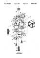
- FIG. 3illustrates an exploded view of the preferred embodiment of the apparatus of the present invention.
- FIGS. 4A-4Frepresent plan elevational views of the apparatus of the present invention mounted in an artificial foot as the foot is undergoing various movements during the walking motion.
- FIG. 1The preferred embodiment of the apparatus of the present invention is illustrated in FIG. 1 by the numeral 10.
- Apparatus 10, for purposes identificationis identified as a multi-axial rotation system for artificial feet or in shorthand a "M.A.R.S.” unit.
- M.A.R.S. unit 10as illustrated, comprises a first upper plate 12, a second lower plate 14, and a first anterior rubber compression spring 16 and a second posterior rubber compression member 18; members 16, 18 positioned intermediate plate or platform members 12 and 14, to form the principal components of the composite ankle system 10 as illustrated.
- upper and lower plate or platform members 12 and 14are reversible in their use.
- anterior compression member 16 and posterior member 18are substantially circular in cross-section, having an upper male threaded screw 32 bonded to compression members 16, 18 and having lower female threaded indented area, on each of the compression members 16, 18.
- the upper and lower of faces 19, 22 of members 16, 18are positioned against the lower surface 26 of lower plate member 14 and the lower surface 28 of upper plate 12 as illustrated in FIG. 1.
- rubber compression members 16, 18are fixedly engaged to the surfaces 26, 28 of plate members 12, 14 via upper bolt 32 onto threaded ports 21 of plate 12, or adhesive bonding, an adhesive bonding material connect the attachment plates 12, 14 to these rubber members 16, 18 to allow lateral flexing of members 16, 18 or via bolting and posterior adhesive bonding only.
- top and bottom plates 12, 14are a principal difference between all previously used memory block type ankle units.
- the rubberized compression spring members 16, 18are of the type manufactured by Lord Industrial Products and are bonded rubber springs constructed of bonded natural rubber compounds which may be natural rubber or a synthetic rubber which are able to transmit a dynamic load, absorb energy, or dissipate energy as the case may be and return these energies.
- the bonded rubber springspermit motion between supporting and supported members in all planes of motions.
- the springsprovide flexibility designed to allow motion without overstressing the components in which the springs are utilized. They also eliminate the need for lubrication by acting as joints or connections to accommodate functional oscillations or deflexions.
- the preferable type of spring mounts utilizedwould be the sandwitch type mount which isolate vibration, absorb shock and atenuating noise due to structure borne vibrations. This construction would assure the proper installation of the mount and improve fatigue life over unbonded designs.
- Pre-compression of the flexing elementtakes place when the anterior of posterior compression bands are applied over plates 12 and 14, or as with the present invention through the use of anterior or posterior compression bands as will be discussed further.
- the anterior member 16, or posterior member 18may be pre-compressed prior to being installed into an artificial foot 40 as illustrated in FIG. 2.
- This pre-compressionis provided by a means which s defined as a compression band 44, as illustrated in FIGS. 1 and 3.
- Band 44is constructed of a flat fabric which is sold under the trademark CORDURA nylon owned by Dupont, and is a flexible fabric. The compression member as illustrated in FIG.
- each of the plate members 12, 14include an anterior milled or slotted area 50 and posterior recess area 52 spanninq the width of the plates 12 and 14 as illustrated.
- the recessed areas 50, 52are substantially the width of the compression member 44, so that with each of the recess areas have upper extending end walls 54, 56 so that when the compression member 44 is wrapped around the heel component 10, as illustrated in FIG. 1, compression member 44 is held in position within recess area for example 52 as seen in FIG. 1, and a slippage of a member can be avoided.
- deflection plate 60which is positioned within foot 40 or is already a fixed part of foot 40, along the length of foot 40 (as illustrated in phantom view in FIG. 2), so as to serve as a long flexible lever arm that may provide appropriate leaf spring for a fluid transition through the gait cycle.
- the mounting of apparatus 10 onto plate 60is provided by several methods.
- the first methodis the use of allen or hex headed bolt nut 62 threaded into a centrally located port 64 in the base of lower plate 14, with the lower end 65 of bolt 62 extending flush or countersunk into the bottom 70 of foot 40, which would secure apparatus 10 in place as seen in FIG. 1. Due to the shortened length of bolt 62, bolt 62 would only extend up to a point substantially flush with the upper surface 26 of plate 14 when in place.
- the upper plate 12would be attached via a second bolt 80 secured into plate 12, and attached to the upper leg portion of the artificial limb, using nut 83, or the existing threaded section in the prosthesis.
- nut 83may be used to attach an artificial foot when the MARS unit is used in the upsidedown configuration.
- the upper plate 12 and lower plate 14would be secured onto both the foot and the upper leg portion respectfully.
- This means of attachmentwould include on the upper side of compression members 16 and 18, a disc member 19 bonded to the rubber compression members 16, 18, via glue or the like, each of the disc 19 having a bolt portion 32 extending upward therefrom, through ports 33 in upper plate 12, and threadably engaged into ports 33.
- each of the disc 19Ahaving an upper depending threaded mounts 21, each of which are insertable into a lower port (not illustrated) in each compression member 16, 18, so that the lower surface 22 of each of the compression members may bondingly adhere to the plates 19A via glue or the like, yet serve as a means for accommodating a pair of bolts 30 through ports 33 in lower plate 14, and to threadably engage within portions 21. Therefore, in full configuration, as illustrated in FIG. 1, the compression members 16, 18, while yet secured to upper plate 12 and lower plate 14, have no rigid bolt or the like through their body portions, and therefore are able to move in the manner as illustrated in FIGS. 4A through 4F, as will be illustrated. As was further discussed, when the component has been bolted together member 44 may be secured through the upper and lower plates, as was discussed more fully in FIG. 1.
- the apparatus 10has been positioned within a hollow 90 in the upper portion of a Symes foot 40 when the lower bolt or allen bolt threadably engaged into the lower portion of the Symes foot 40 for mounting thereinto.
- the upper bolt 80would be threadably engaged into the upper leg portion of the prosthetic combination of the amputee, it would be properly mounted onto the base plate 60 located in foot 40.
- FIGS. 4A-4Frepresent the various dynamic movements of the apparatus during the gait movement of a foot during walking.
- foot member 40having apparatus 10 mounted onto base plate 60.
- the apparatusis seen without the use of the anterior or posterior compression bands 44, so that a clear view of the movement of compression springs 16 and 18 may be viewed in full view.
- anterior or posterior compression bands 44 MARS unitmay function with anterior band missing but it cannot function with just an anterior band, for safety it is best to have both bands, or both in combination with the apparatus.
- the footis positioned in the heel off position i.e., with the heel 41 of foot 40, moved off of a surface 70 and the ball 43 of the foot 40, striking the surface 70.
- the anterior compression memberhas been compressed with the sidewall 17 bulging outward under the force of the compression, yet at the same time the posterior compression member 18 has be stretched so that the sidewall 17 forms a concave shape as the compression member 16 is being expanded through the movement of the ankle.
- FIG. 4Bwould illustrate the heel 41 striking the surface 70, with the ball 43 of the foot 40 raised off of the surface.
- the posterior compression spring 18is being compressed with the sidewall 17 expanding outward, and the anterior compression member 16 is non-compressed, and in the normal unstressed position.
- FIG. 4Cthe foot is in the position where the toe 45 is striking the surface 70, with the ball 43 and heel 41 of foot 40 moved off of the surface.
- the posterior compression member 18is stretched inwardly, with the anterior member 16 compressed but not as severely as seen in FIG. 4A when the ball of the foot is striking, because energy is being returned propulsion.
- the footis in the "flat foot” position with the heel 41 and ball 43 of foot 40 striking the floor, with the toe 45 raised off of the surface 70.
- the anterior member 16is stretched inwardly so that wall 17 forms a concave central portion with the posterior member 18 compressed so that the wall 17 is bulging outwardly as indicated.
- 4Fillustrates the anterior member 16 and posterior member 18 as each is undergoing inversion and eversion respectively during the wearing of the apparatus.
- This particular view of the springsindicates the movement of the compression members 16, 18 while this stress is being placed there upon.
- FIGS. 4A-4Edo not illustrate the use of the anterior or posterior compression bands 44.
- compression bands 44With the use of compression bands 44 in place, as seen in FIG. 1, the stretching of the anterior or posterior member 16, 18 is restricted, in that each of the members are pre-compressed when the band is in place, and therefore undergo minimum stretching as the case may be. This is done so that the wearer is given predetermined amount of movement of the compression members while going through the walking gait when being worn.
- top and bottom platesmay undergo a shear movement, in that the end of the plates are twisted yet due to the resilent factor of members 16, 18 allows the shear movement to return to its original alignment.
Landscapes
- Health & Medical Sciences (AREA)
- Transplantation (AREA)
- Biomedical Technology (AREA)
- Cardiology (AREA)
- Oral & Maxillofacial Surgery (AREA)
- Engineering & Computer Science (AREA)
- Orthopedic Medicine & Surgery (AREA)
- Heart & Thoracic Surgery (AREA)
- Vascular Medicine (AREA)
- Life Sciences & Earth Sciences (AREA)
- Animal Behavior & Ethology (AREA)
- General Health & Medical Sciences (AREA)
- Public Health (AREA)
- Veterinary Medicine (AREA)
- Prostheses (AREA)
Abstract
Description
Claims (15)
Priority Applications (2)
| Application Number | Priority Date | Filing Date | Title |
|---|---|---|---|
| US07/492,885US5019109A (en) | 1990-03-09 | 1990-03-09 | Multi-axial rotation system for artificial ankle |
| CA002034803ACA2034803C (en) | 1990-03-09 | 1991-01-23 | Multi-axial rotation system for artificial ankle |
Applications Claiming Priority (1)
| Application Number | Priority Date | Filing Date | Title |
|---|---|---|---|
| US07/492,885US5019109A (en) | 1990-03-09 | 1990-03-09 | Multi-axial rotation system for artificial ankle |
Publications (1)
| Publication Number | Publication Date |
|---|---|
| US5019109Atrue US5019109A (en) | 1991-05-28 |
Family
ID=23957996
Family Applications (1)
| Application Number | Title | Priority Date | Filing Date |
|---|---|---|---|
| US07/492,885Expired - LifetimeUS5019109A (en) | 1990-03-09 | 1990-03-09 | Multi-axial rotation system for artificial ankle |
Country Status (2)
| Country | Link |
|---|---|
| US (1) | US5019109A (en) |
| CA (1) | CA2034803C (en) |
Cited By (99)
| Publication number | Priority date | Publication date | Assignee | Title |
|---|---|---|---|---|
| US5290319A (en)* | 1991-02-28 | 1994-03-01 | Phillips L Van | Prosthetic foot incorporating adjustable bladders |
| US5295932A (en)* | 1990-02-05 | 1994-03-22 | Rowan Michael G | Stilts |
| US5314499A (en)* | 1991-04-04 | 1994-05-24 | Collier Jr Milo S | Artificial limb including a shin, ankle and foot |
| US5387246A (en)* | 1989-04-13 | 1995-02-07 | Phillips; Van L. | Prosthetic ski leg |
| US5425782A (en)* | 1992-03-11 | 1995-06-20 | Phillips; Van L. | Alignment fixture for prosthetic device |
| US5458656A (en)* | 1991-09-30 | 1995-10-17 | Flex-Foot | Energy-storing prosthesis leg pylon vertical shock leg |
| US5486209A (en)* | 1989-04-13 | 1996-01-23 | Phillips; Van L. | Foot prosthesis having auxiliary ankle construction |
| US5509936A (en)* | 1994-06-30 | 1996-04-23 | Rappoport; Albert F. | Dual leaf spring strut system |
| US5514186A (en)* | 1989-04-13 | 1996-05-07 | Phillips; Van L. | Attachment construction for prosthesis |
| US5514185A (en) | 1991-02-28 | 1996-05-07 | Phillips; Van L. | Split foot prosthesis |
| US5549714A (en)* | 1990-09-21 | 1996-08-27 | Phillips; Van L. | Symes foot prosthesis |
| US5571212A (en)* | 1995-01-10 | 1996-11-05 | M+Ind (Model & Instrument Development Corporation | Prosthetic ankle joint for pivotally connecting a residual limb to a prosthetic foot |
| US5571213A (en)* | 1992-11-17 | 1996-11-05 | Allen; Scott | Prosthetic foot |
| US5728177A (en)* | 1994-08-15 | 1998-03-17 | Flex-Foot, Inc. | Prosthesis with foam block ankle |
| US5766264A (en)* | 1996-08-30 | 1998-06-16 | United States Manufacturing Company | Multi-axis prosthetic ankle joint |
| US5944760A (en)* | 1997-08-04 | 1999-08-31 | Roland J. Christensen Family Limited Partnership | Prosthetic foot with reinforcing member |
| US5984972A (en)* | 1997-09-18 | 1999-11-16 | Amputee Solutions, Inc. | Pylon assembly for leg prosthesis |
| US6120547A (en)* | 1998-11-06 | 2000-09-19 | Roland J. Christensen | Enhanced prosthetic foot structure with ankle reinforcement |
| GB2348813A (en)* | 1999-04-16 | 2000-10-18 | Vessa Ltd | Prosthetic foot |
| US6206934B1 (en) | 1998-04-10 | 2001-03-27 | Flex-Foot, Inc. | Ankle block with spring inserts |
| US6241776B1 (en) | 1997-08-04 | 2001-06-05 | Roland Christensen | Prosthetic foot with reinforcing member |
| US6290730B1 (en)* | 1999-03-26 | 2001-09-18 | Ohio Willow Wood Company | Artificial foot and ankle |
| WO2002002034A1 (en)* | 2000-06-30 | 2002-01-10 | Roland J. Christensen, As Operating Manager Of Rjc Development, Lc, General Partner Of The Roland J. Christensen Family Limited Partnership | Prosthetic foot |
| WO2002022056A1 (en)* | 2000-09-15 | 2002-03-21 | Bjarni Ellert Isleifsson | Ankle joints |
| US6406500B1 (en) | 1989-04-13 | 2002-06-18 | Van L. Phillips | Foot prosthesis having curved forefoot |
| US6443995B1 (en) | 2000-12-22 | 2002-09-03 | Barry W. Townsend | Prosthetic foot |
| US20020128727A1 (en)* | 1999-07-02 | 2002-09-12 | Merlette John B. | Lower leg prosthesis |
| US6478826B1 (en) | 1998-04-10 | 2002-11-12 | Van L. Phillips | Shock module prosthesis |
| US6511512B2 (en) | 1998-04-10 | 2003-01-28 | Ossur Hf | Active shock module prosthesis |
| US20030028256A1 (en)* | 2001-03-30 | 2003-02-06 | Townsend Barry W. | Prosthetic foot with tunable performance |
| US20030093158A1 (en)* | 2000-10-26 | 2003-05-15 | Phillips Van L. | Foot prosthesis having cushioned ankle |
| US20030191541A1 (en)* | 2000-08-30 | 2003-10-09 | Phillips Van L. | Energy storing foot prosthesis with improved plantar flexion |
| US6699295B2 (en) | 2001-06-29 | 2004-03-02 | Ohio Willow Wood Company | Multi-axis prosthetic ankle joint |
| US20040068327A1 (en)* | 2002-10-08 | 2004-04-08 | Christensen Roland J. | Prosthetic foot with a resilient ankle |
| US20040117036A1 (en)* | 2001-03-30 | 2004-06-17 | Townsend Barry W | Prosthetic foot with tunable performance |
| US20040186592A1 (en)* | 2001-03-30 | 2004-09-23 | Townsend Barry W. | Prosthetic foot with tunable performance |
| US20040199265A1 (en)* | 2000-12-22 | 2004-10-07 | Townsend Barry W. | Prosthetic foot |
| US6805717B2 (en) | 2002-10-08 | 2004-10-19 | Roland J. Christensen, As Operating Manager Of Rjc Development, Lc, General Manager Of The Roland J. Christensen Family Limited Partnership | Energy-storing prosthetic foot with elongated forefoot |
| US20040225376A1 (en)* | 2000-12-22 | 2004-11-11 | Townsend Barry W. | Prosthetic foot |
| US20050015157A1 (en)* | 2001-06-29 | 2005-01-20 | The Ohio Willow Wood | Multi-axis prosthetic ankle joint |
| US20050033450A1 (en)* | 2002-10-08 | 2005-02-10 | Christensen Roland J. | Prosthetic foot with a resilient ankle |
| US20050038524A1 (en)* | 2003-08-15 | 2005-02-17 | Jonsson Orn Ingvi | Low profile prosthetic foot |
| US20050060045A1 (en)* | 2003-09-16 | 2005-03-17 | Smith Nolan L. | Multi-axial prosthetic foot |
| US20050071017A1 (en)* | 2003-09-30 | 2005-03-31 | Lecomte Christophe Guy | Low profile active shock module prosthesis |
| US6875241B2 (en) | 2000-06-30 | 2005-04-05 | Roland J. Christensen, As Operating Manager Of Rjc Development Lc, General Partner Of The Roland J. Christensen Family Limited Partnership | Variable resistance cell |
| US20050085926A1 (en)* | 2003-10-21 | 2005-04-21 | General Partner Of The Roland J. Christensen Family Limited Partnership | Prosthetic foot with an adjustable ankle and method |
| US6899737B1 (en) | 1998-04-10 | 2005-05-31 | Van L. Phillips | Foot prosthesis having cushioned ankle |
| US20050137717A1 (en)* | 2003-12-18 | 2005-06-23 | Finn Gramnas | Prosthetic foot with rocker member |
| US6911052B2 (en) | 2002-10-08 | 2005-06-28 | Roland J. Christensen, As Operating Manager Of Rjc Development, Lc, General Partner Of The Roland J. Christensen Family Limited Partnership | Prosthetic foot with oblique attachment |
| US20050171618A1 (en)* | 2000-06-30 | 2005-08-04 | Christensen Roland J. | Prosthetic foot with energy transfer including variable orifice |
| US20050187640A1 (en)* | 2004-02-20 | 2005-08-25 | Roland J. Christensen | Prosthetic foot with cam |
| US20050192673A1 (en)* | 2003-10-14 | 2005-09-01 | Saltzman Charles L. | Ankle prosthesis and method for implanting ankle prosthesis |
| US20050216098A1 (en)* | 2000-06-30 | 2005-09-29 | Roland J. Christensen | Variable resistance cell |
| US20050261783A1 (en)* | 2004-05-19 | 2005-11-24 | Otto Bock Healthcare Lp | Multi-axial fitting with shock absorption for prosthetic foot |
| US20050267603A1 (en)* | 2004-05-28 | 2005-12-01 | Lecomte Christophe G | Foot prosthesis with resilient multi-axial ankle |
| US20050284160A1 (en)* | 2004-06-25 | 2005-12-29 | Johnson Controls Technology Company | Method of and apparatus for evaluating the performance of a control system |
| US20050288792A1 (en)* | 2004-06-23 | 2005-12-29 | Landes Mark D | Modular ankle prosthesis and associated method |
| US20060041321A1 (en)* | 2003-10-21 | 2006-02-23 | Christensen Roland J | Prosthetic foot with an adjustable ankle and method |
| US20060058893A1 (en)* | 2004-05-28 | 2006-03-16 | Clausen Arinbjorn V | Method of measuring the performance of a prosthetic foot |
| US20060069450A1 (en)* | 2004-09-18 | 2006-03-30 | Otto Bock Healthcare Lp | Lower leg prosthesis with improved roll over |
| US20060178754A1 (en)* | 2001-03-30 | 2006-08-10 | Townsend Barry W | Prosthetic foot with tunable performance and improved vertical load/shock absorption |
| US20060229736A1 (en)* | 2000-06-30 | 2006-10-12 | Christensen Roland J | Prosthetic foot with energy transfer |
| US20060241783A1 (en)* | 2000-06-30 | 2006-10-26 | Christensen Roland J | Variable resistance cell |
| US20060247794A1 (en)* | 2001-06-29 | 2006-11-02 | The Ohio Willow Wood Company | Multi-axis prosthetic ankle |
| US20070106396A1 (en)* | 2001-06-29 | 2007-05-10 | The Ohio Willow Wood Company | Multi-axis prosthetic ankle |
| US20070213841A1 (en)* | 2001-03-30 | 2007-09-13 | Townsend Barry W | Prosthetic foot with tunable performance |
| US20070213840A1 (en)* | 2003-09-30 | 2007-09-13 | Townsend Barry W | Prosthetic Foot with Tunable Performance |
| US20070219643A1 (en)* | 2004-04-01 | 2007-09-20 | Townsend Barry W | Prosthetic Foot With Tunable Performance |
| US20070255427A1 (en)* | 2004-08-04 | 2007-11-01 | Ralf Kloos | Prosthesis, in Particular Prosthetic Foot |
| US20080033578A1 (en)* | 2006-08-03 | 2008-02-07 | Christensen Roland J | Prosthetic foot with variable medial/lateral stiffness |
| US7374578B2 (en) | 2001-03-30 | 2008-05-20 | Bioquest Prosthetics, Llc | Prosthetic foot with tunable performance |
| US20080167731A1 (en)* | 2006-12-06 | 2008-07-10 | Christensen Roland J | Prosthetic foot with longer upper forefoot and shorter lower forefoot |
| US20080183301A1 (en)* | 2000-06-30 | 2008-07-31 | Christensen Roland J | Prosthetic foot with energy transfer |
| US20080188951A1 (en)* | 2007-01-30 | 2008-08-07 | Christensen Roland J | Prosthetic foot with variable medial/lateral stiffness |
| US7429272B2 (en) | 2001-03-30 | 2008-09-30 | Bioquest Prosthetics Llc | Prosthetic foot with tunable performance |
| US7462201B2 (en) | 2003-10-21 | 2008-12-09 | Freedom Innovations, Llc | Prosthetic foot with an adjustable ankle and method |
| US20090082878A1 (en)* | 2007-09-18 | 2009-03-26 | Christensen Roland J | Multi-axial prosthetic ankle |
| US20090265019A1 (en)* | 2008-04-18 | 2009-10-22 | Chritstensen Roland J | Prosthetic foot with two leaf-springs joined at heel and toe |
| US7611543B2 (en) | 2001-03-30 | 2009-11-03 | Bioquest Prosthetics, Llc | Prosthetic foot with tunable performance |
| US20100004757A1 (en)* | 2008-07-01 | 2010-01-07 | Ossur Hf | Smooth rollover insole for prosthetic foot |
| US20110071650A1 (en)* | 2003-09-30 | 2011-03-24 | Townsend Barry W | Resilient prosthetic and orthotic components which incorporate a plurality of sagittally oriented struts |
| US20110213471A1 (en)* | 2010-02-26 | 2011-09-01 | össur hf | Prosthetic foot with a curved split |
| US8236062B2 (en) | 2001-03-30 | 2012-08-07 | Bioquest Prosthetics Llc | Prosthetic foot with tunable performance |
| US8500825B2 (en) | 2010-06-29 | 2013-08-06 | Freedom Innovations, Llc | Prosthetic foot with floating forefoot keel |
| US8961618B2 (en) | 2011-12-29 | 2015-02-24 | össur hf | Prosthetic foot with resilient heel |
| US9351853B2 (en) | 2008-08-18 | 2016-05-31 | The Ohio Willow Wood Company | Prosthetic foot |
| USD795433S1 (en) | 2015-06-30 | 2017-08-22 | Össur Iceland Ehf | Prosthetic foot cover |
| USD797292S1 (en) | 2014-06-30 | 2017-09-12 | össur hf | Prosthetic foot plate |
| FR3071717A1 (en)* | 2017-10-03 | 2019-04-05 | Aster 3D | FLEXIBLE ANCHOR DEVICE FOR LOWER LIMBS PROSTHESIS |
| US10251762B2 (en) | 2011-05-03 | 2019-04-09 | Victhom Laboratory Inc. | Impedance simulating motion controller for orthotic and prosthetic applications |
| WO2020180378A1 (en)* | 2019-03-06 | 2020-09-10 | Impulse Technology LLC | Self-alignment device for passive prosthetics |
| US10821007B2 (en) | 2016-12-01 | 2020-11-03 | Össur Iceland Ehf | Prosthetic feet having heel height adjustability |
| USD915596S1 (en) | 2018-04-10 | 2021-04-06 | Össur Iceland Ehf | Prosthetic foot with tapered fasteners |
| US10980648B1 (en) | 2017-09-15 | 2021-04-20 | Össur Iceland Ehf | Variable stiffness mechanism and limb support device incorporating the same |
| US20220087834A1 (en)* | 2019-01-25 | 2022-03-24 | Ottobock Se & Co. Kgaa | Prosthetic foot component |
| US11446164B1 (en) | 2017-09-15 | 2022-09-20 | Össur Iceland Ehf | Variable stiffness mechanisms |
| IT202200023433A1 (en)* | 2022-11-14 | 2024-05-14 | Isinnova S R L | PROSTHETIC FOOT, PROSTHETIC LEG, AS WELL AS KIT FOR OBTAINING A UNIVERSAL PROSTHESIS FOR A LOWER LIMB AND METHOD OF ASSEMBLING THE LATTER |
| US12201537B2 (en) | 2020-11-30 | 2025-01-21 | Össur Iceland Ehf | Prosthetic foot with layers of fibrous material |
| US12414867B1 (en) | 2018-06-01 | 2025-09-16 | Össur Iceland Ehf | Prosthetic feet with increased flexibility to accommodate different heel heights |
Citations (3)
| Publication number | Priority date | Publication date | Assignee | Title |
|---|---|---|---|---|
| US2357893A (en)* | 1943-06-14 | 1944-09-12 | Noel F Harrington | Ankle joint for artificial limbs |
| US4364128A (en)* | 1981-08-31 | 1982-12-21 | Jobst Institute, Inc. | Artificial foot |
| US4605417A (en)* | 1984-10-03 | 1986-08-12 | Fleischauer K E | Prosthetic joint |
- 1990
- 1990-03-09USUS07/492,885patent/US5019109A/ennot_activeExpired - Lifetime
- 1991
- 1991-01-23CACA002034803Apatent/CA2034803C/ennot_activeExpired - Fee Related
Patent Citations (3)
| Publication number | Priority date | Publication date | Assignee | Title |
|---|---|---|---|---|
| US2357893A (en)* | 1943-06-14 | 1944-09-12 | Noel F Harrington | Ankle joint for artificial limbs |
| US4364128A (en)* | 1981-08-31 | 1982-12-21 | Jobst Institute, Inc. | Artificial foot |
| US4605417A (en)* | 1984-10-03 | 1986-08-12 | Fleischauer K E | Prosthetic joint |
Cited By (194)
| Publication number | Priority date | Publication date | Assignee | Title |
|---|---|---|---|---|
| US6527811B1 (en) | 1989-04-13 | 2003-03-04 | Van L. Phillips | Foot prosthesis with modular foot plate |
| US5387246A (en)* | 1989-04-13 | 1995-02-07 | Phillips; Van L. | Prosthetic ski leg |
| US5976191A (en)* | 1989-04-13 | 1999-11-02 | Phillips; Van L. | Foot prosthesis having curved forefoot |
| US5728176A (en)* | 1989-04-13 | 1998-03-17 | Flex-Foot, Inc. | Attachment construction for prosthesis |
| US5486209A (en)* | 1989-04-13 | 1996-01-23 | Phillips; Van L. | Foot prosthesis having auxiliary ankle construction |
| US6406500B1 (en) | 1989-04-13 | 2002-06-18 | Van L. Phillips | Foot prosthesis having curved forefoot |
| US5593457A (en)* | 1989-04-13 | 1997-01-14 | Phillips; Van L. | Foot prosthesis having auxiliary ankle construction |
| US5514186A (en)* | 1989-04-13 | 1996-05-07 | Phillips; Van L. | Attachment construction for prosthesis |
| US5295932A (en)* | 1990-02-05 | 1994-03-22 | Rowan Michael G | Stilts |
| US5549714A (en)* | 1990-09-21 | 1996-08-27 | Phillips; Van L. | Symes foot prosthesis |
| US5509938A (en) | 1991-02-28 | 1996-04-23 | Phillips; Van L. | Prosthetic foot incorporating adjustable bladder |
| US5514185A (en) | 1991-02-28 | 1996-05-07 | Phillips; Van L. | Split foot prosthesis |
| US5290319A (en)* | 1991-02-28 | 1994-03-01 | Phillips L Van | Prosthetic foot incorporating adjustable bladders |
| US5314499A (en)* | 1991-04-04 | 1994-05-24 | Collier Jr Milo S | Artificial limb including a shin, ankle and foot |
| US5458656A (en)* | 1991-09-30 | 1995-10-17 | Flex-Foot | Energy-storing prosthesis leg pylon vertical shock leg |
| US5425782A (en)* | 1992-03-11 | 1995-06-20 | Phillips; Van L. | Alignment fixture for prosthetic device |
| US5571213A (en)* | 1992-11-17 | 1996-11-05 | Allen; Scott | Prosthetic foot |
| US5509936A (en)* | 1994-06-30 | 1996-04-23 | Rappoport; Albert F. | Dual leaf spring strut system |
| US7354456B2 (en) | 1994-08-15 | 2008-04-08 | Phillips Van L | Foot prosthesis having cushioned ankle |
| US5800569A (en)* | 1994-08-15 | 1998-09-01 | Phillips; Van L. | Prosthesis with resilient ankle block |
| US5993488A (en)* | 1994-08-15 | 1999-11-30 | Phillips; Van L. | Prosthesis with resilient ankle block |
| US5728177A (en)* | 1994-08-15 | 1998-03-17 | Flex-Foot, Inc. | Prosthesis with foam block ankle |
| US20050234563A1 (en)* | 1994-08-15 | 2005-10-20 | Phillips Van L | Foot prosthesis having cushioned ankle |
| US5571212A (en)* | 1995-01-10 | 1996-11-05 | M+Ind (Model & Instrument Development Corporation | Prosthetic ankle joint for pivotally connecting a residual limb to a prosthetic foot |
| US5766264A (en)* | 1996-08-30 | 1998-06-16 | United States Manufacturing Company | Multi-axis prosthetic ankle joint |
| US5944760A (en)* | 1997-08-04 | 1999-08-31 | Roland J. Christensen Family Limited Partnership | Prosthetic foot with reinforcing member |
| US6241776B1 (en) | 1997-08-04 | 2001-06-05 | Roland Christensen | Prosthetic foot with reinforcing member |
| US5984972A (en)* | 1997-09-18 | 1999-11-16 | Amputee Solutions, Inc. | Pylon assembly for leg prosthesis |
| US7879110B2 (en) | 1998-04-10 | 2011-02-01 | Ossur Hf | Foot prosthesis having cushioned ankle |
| US7279011B2 (en) | 1998-04-10 | 2007-10-09 | Phillips Van L | Foot prosthesis having cushioned ankle |
| US20100106260A1 (en)* | 1998-04-10 | 2010-04-29 | Phillips Van L | Foot prosthesis having cushioned ankle |
| US20040068325A1 (en)* | 1998-04-10 | 2004-04-08 | Phillips Van L. | Shock module prosthesis |
| US6887279B2 (en) | 1998-04-10 | 2005-05-03 | össur hf | Active shock module prosthesis |
| US7169190B2 (en) | 1998-04-10 | 2007-01-30 | Van L. Phillips | Active shock module prosthesis |
| US6899737B1 (en) | 1998-04-10 | 2005-05-31 | Van L. Phillips | Foot prosthesis having cushioned ankle |
| US6478826B1 (en) | 1998-04-10 | 2002-11-12 | Van L. Phillips | Shock module prosthesis |
| US6511512B2 (en) | 1998-04-10 | 2003-01-28 | Ossur Hf | Active shock module prosthesis |
| US20040162623A1 (en)* | 1998-04-10 | 2004-08-19 | Phillips Van L. | Foot prosthesis having cushioned ankle |
| US6280479B1 (en) | 1998-04-10 | 2001-08-28 | Flex-Foot, Inc. | Foot prosthesis having cushioned ankle |
| US20050209707A1 (en)* | 1998-04-10 | 2005-09-22 | Phillips Van L | Active shock module prosthesis |
| US6206934B1 (en) | 1998-04-10 | 2001-03-27 | Flex-Foot, Inc. | Ankle block with spring inserts |
| US6120547A (en)* | 1998-11-06 | 2000-09-19 | Roland J. Christensen | Enhanced prosthetic foot structure with ankle reinforcement |
| US6290730B1 (en)* | 1999-03-26 | 2001-09-18 | Ohio Willow Wood Company | Artificial foot and ankle |
| GB2348813A (en)* | 1999-04-16 | 2000-10-18 | Vessa Ltd | Prosthetic foot |
| US6387134B1 (en) | 1999-04-16 | 2002-05-14 | Vessa Limited | Prosthetic foot |
| US20020128727A1 (en)* | 1999-07-02 | 2002-09-12 | Merlette John B. | Lower leg prosthesis |
| US20050216098A1 (en)* | 2000-06-30 | 2005-09-29 | Roland J. Christensen | Variable resistance cell |
| US7686848B2 (en) | 2000-06-30 | 2010-03-30 | Freedom Innovations, Llc | Prosthetic foot with energy transfer |
| US20040133284A1 (en)* | 2000-06-30 | 2004-07-08 | Christensen Roland J. | Prosthetic foot with energy transfer medium including variable viscosity fluid |
| WO2002002034A1 (en)* | 2000-06-30 | 2002-01-10 | Roland J. Christensen, As Operating Manager Of Rjc Development, Lc, General Partner Of The Roland J. Christensen Family Limited Partnership | Prosthetic foot |
| US6663673B2 (en) | 2000-06-30 | 2003-12-16 | Roland J. Christensen | Prosthetic foot with energy transfer medium including variable viscosity fluid |
| US20080183301A1 (en)* | 2000-06-30 | 2008-07-31 | Christensen Roland J | Prosthetic foot with energy transfer |
| US6875241B2 (en) | 2000-06-30 | 2005-04-05 | Roland J. Christensen, As Operating Manager Of Rjc Development Lc, General Partner Of The Roland J. Christensen Family Limited Partnership | Variable resistance cell |
| US20050171618A1 (en)* | 2000-06-30 | 2005-08-04 | Christensen Roland J. | Prosthetic foot with energy transfer including variable orifice |
| US6875242B2 (en) | 2000-06-30 | 2005-04-05 | Roland J. Christensen, As Operating Manager Of Rjc Development, Lc, General Partner Of The Roland J. Christensen Family Limited Partnership | Prosthetic foot with energy transfer medium including variable viscosity fluid |
| US7341603B2 (en) | 2000-06-30 | 2008-03-11 | Applied Composite Technology, Inc. | Prosthetic foot with energy transfer including variable orifice |
| US20060229736A1 (en)* | 2000-06-30 | 2006-10-12 | Christensen Roland J | Prosthetic foot with energy transfer |
| US20060241783A1 (en)* | 2000-06-30 | 2006-10-26 | Christensen Roland J | Variable resistance cell |
| US7572299B2 (en) | 2000-06-30 | 2009-08-11 | Freedom Innovations, Llc | Prosthetic foot with energy transfer |
| US20030191541A1 (en)* | 2000-08-30 | 2003-10-09 | Phillips Van L. | Energy storing foot prosthesis with improved plantar flexion |
| US7060104B2 (en) | 2000-08-30 | 2006-06-13 | Phillips Van L | Energy storing foot prosthesis with improved plantar flexion |
| WO2002022056A1 (en)* | 2000-09-15 | 2002-03-21 | Bjarni Ellert Isleifsson | Ankle joints |
| US7063727B2 (en) | 2000-10-26 | 2006-06-20 | Van L. Phillips | Foot prosthesis having cushioned ankle |
| US20030093158A1 (en)* | 2000-10-26 | 2003-05-15 | Phillips Van L. | Foot prosthesis having cushioned ankle |
| US7108723B2 (en) | 2000-12-22 | 2006-09-19 | Townsend Barry W | Prosthetic foot |
| US6443995B1 (en) | 2000-12-22 | 2002-09-03 | Barry W. Townsend | Prosthetic foot |
| US20040225376A1 (en)* | 2000-12-22 | 2004-11-11 | Townsend Barry W. | Prosthetic foot |
| US20040199265A1 (en)* | 2000-12-22 | 2004-10-07 | Townsend Barry W. | Prosthetic foot |
| US6743260B2 (en) | 2000-12-22 | 2004-06-01 | Barry W. Townsend | Prosthetic foot |
| US6936074B2 (en) | 2000-12-22 | 2005-08-30 | Barry W. Townsend | Prosthetic foot |
| US7578852B2 (en) | 2001-03-30 | 2009-08-25 | Bioquest Prosthetics, Llc | Prosthetic foot with tunable performance and improved vertical load/shock absorption |
| US7374578B2 (en) | 2001-03-30 | 2008-05-20 | Bioquest Prosthetics, Llc | Prosthetic foot with tunable performance |
| US20080183302A1 (en)* | 2001-03-30 | 2008-07-31 | Townsend Barry W | Prosthetic foot with tunable performance |
| US20030191540A1 (en)* | 2001-03-30 | 2003-10-09 | Townsend Barry W. | Prosthetic foot with tunable performance |
| US7364593B2 (en) | 2001-03-30 | 2008-04-29 | Bioquest Prosthetics Llc | Prosthetic foot with tunable performance |
| US7410503B2 (en) | 2001-03-30 | 2008-08-12 | Bioquest Prosthetics Llc | Prosthetic foot with tunable performance |
| US7429272B2 (en) | 2001-03-30 | 2008-09-30 | Bioquest Prosthetics Llc | Prosthetic foot with tunable performance |
| US20030028256A1 (en)* | 2001-03-30 | 2003-02-06 | Townsend Barry W. | Prosthetic foot with tunable performance |
| US20070213841A1 (en)* | 2001-03-30 | 2007-09-13 | Townsend Barry W | Prosthetic foot with tunable performance |
| US7226485B2 (en) | 2001-03-30 | 2007-06-05 | Bioquest Prosthetics, Llc | Prosthetic foot with tunable performance |
| US7211115B2 (en) | 2001-03-30 | 2007-05-01 | Townsend Barry W | Prosthetic foot with tunable performance |
| US8236062B2 (en) | 2001-03-30 | 2012-08-07 | Bioquest Prosthetics Llc | Prosthetic foot with tunable performance |
| US7507259B2 (en) | 2001-03-30 | 2009-03-24 | Bioquest Prosthetics, Llc | Prosthetic foot with tunable performance |
| US20040117036A1 (en)* | 2001-03-30 | 2004-06-17 | Townsend Barry W | Prosthetic foot with tunable performance |
| US7611543B2 (en) | 2001-03-30 | 2009-11-03 | Bioquest Prosthetics, Llc | Prosthetic foot with tunable performance |
| US7708784B2 (en) | 2001-03-30 | 2010-05-04 | Bioquest Prosthetics, Llc | Prosthetic foot with tunable performance |
| US20060178754A1 (en)* | 2001-03-30 | 2006-08-10 | Townsend Barry W | Prosthetic foot with tunable performance and improved vertical load/shock absorption |
| US20040186592A1 (en)* | 2001-03-30 | 2004-09-23 | Townsend Barry W. | Prosthetic foot with tunable performance |
| US20060247794A1 (en)* | 2001-06-29 | 2006-11-02 | The Ohio Willow Wood Company | Multi-axis prosthetic ankle |
| US6699295B2 (en) | 2001-06-29 | 2004-03-02 | Ohio Willow Wood Company | Multi-axis prosthetic ankle joint |
| US7563288B2 (en) | 2001-06-29 | 2009-07-21 | The Ohio Willow Wood Company | Multi-axis prosthetic ankle |
| US7112227B2 (en) | 2001-06-29 | 2006-09-26 | The Ohio Willow Wood Company | Multi-axis prosthetic ankle joint |
| US20050015157A1 (en)* | 2001-06-29 | 2005-01-20 | The Ohio Willow Wood | Multi-axis prosthetic ankle joint |
| US7833287B2 (en) | 2001-06-29 | 2010-11-16 | The Ohio Willow Wood Company | Adjustable multi-axis prosthetic ankle and method of use thereof |
| US20070106396A1 (en)* | 2001-06-29 | 2007-05-10 | The Ohio Willow Wood Company | Multi-axis prosthetic ankle |
| US7419509B2 (en) | 2002-10-08 | 2008-09-02 | Freedom Innovations, Llc | Prosthetic foot with a resilient ankle |
| US6911052B2 (en) | 2002-10-08 | 2005-06-28 | Roland J. Christensen, As Operating Manager Of Rjc Development, Lc, General Partner Of The Roland J. Christensen Family Limited Partnership | Prosthetic foot with oblique attachment |
| US20050033450A1 (en)* | 2002-10-08 | 2005-02-10 | Christensen Roland J. | Prosthetic foot with a resilient ankle |
| US6929665B2 (en) | 2002-10-08 | 2005-08-16 | Roland J. Christensen | Prosthetic foot with a resilient ankle |
| US6805717B2 (en) | 2002-10-08 | 2004-10-19 | Roland J. Christensen, As Operating Manager Of Rjc Development, Lc, General Manager Of The Roland J. Christensen Family Limited Partnership | Energy-storing prosthetic foot with elongated forefoot |
| US20040068327A1 (en)* | 2002-10-08 | 2004-04-08 | Christensen Roland J. | Prosthetic foot with a resilient ankle |
| US8377144B2 (en) | 2003-08-15 | 2013-02-19 | Ossur Hf | Low profile prosthetic foot |
| US8377146B2 (en) | 2003-08-15 | 2013-02-19 | Ossur Hf | Low profile prosthetic foot |
| US9579220B2 (en) | 2003-08-15 | 2017-02-28 | össur hf | Low profile prosthetic foot |
| US20050038524A1 (en)* | 2003-08-15 | 2005-02-17 | Jonsson Orn Ingvi | Low profile prosthetic foot |
| US8007544B2 (en) | 2003-08-15 | 2011-08-30 | Ossur Hf | Low profile prosthetic foot |
| US8858649B2 (en) | 2003-08-15 | 2014-10-14 | össur hf | Low profile prosthetic foot |
| US20070027557A1 (en)* | 2003-08-15 | 2007-02-01 | Jonsson Orn I | Low profile prosthetic foot |
| US20050060045A1 (en)* | 2003-09-16 | 2005-03-17 | Smith Nolan L. | Multi-axial prosthetic foot |
| US8808395B2 (en) | 2003-09-30 | 2014-08-19 | Bioquest Prosthetics, LLC. | Resilient prosthetic and orthotic components which incorporate a plurality of sagittally oriented struts |
| US20050071017A1 (en)* | 2003-09-30 | 2005-03-31 | Lecomte Christophe Guy | Low profile active shock module prosthesis |
| US8574314B2 (en) | 2003-09-30 | 2013-11-05 | Bioquest Prosthetics Llc | Resilient prosthetic and orthotic components which incorporate a plurality of sagittally oriented struts |
| US8070829B2 (en) | 2003-09-30 | 2011-12-06 | Bioquest Prosthetics Llc | Prosthetic foot with tunable performance |
| US7371262B2 (en) | 2003-09-30 | 2008-05-13 | össur hf | Low profile active shock module prosthesis |
| US6969408B2 (en) | 2003-09-30 | 2005-11-29 | Ossur Engineering, Inc. | Low profile active shock module prosthesis |
| US20110071650A1 (en)* | 2003-09-30 | 2011-03-24 | Townsend Barry W | Resilient prosthetic and orthotic components which incorporate a plurality of sagittally oriented struts |
| US20060004467A1 (en)* | 2003-09-30 | 2006-01-05 | Lecomte Christophe G | Low profile active shock module prosthesis |
| US20070213840A1 (en)* | 2003-09-30 | 2007-09-13 | Townsend Barry W | Prosthetic Foot with Tunable Performance |
| US20050192673A1 (en)* | 2003-10-14 | 2005-09-01 | Saltzman Charles L. | Ankle prosthesis and method for implanting ankle prosthesis |
| US8636744B2 (en) | 2003-10-14 | 2014-01-28 | University Of Iowa Research Foundation | Positioning device for ankle joint replacement surgery |
| US7963996B2 (en) | 2003-10-14 | 2011-06-21 | University Of Iowa Research Foundation | Ankle prosthesis methods |
| US7625409B2 (en) | 2003-10-14 | 2009-12-01 | University Of Iowa Research Foundation | Ankle prosthesis |
| US20100305572A1 (en)* | 2003-10-14 | 2010-12-02 | Saltzman Charles L | Ankle prosthesis methods |
| US7462201B2 (en) | 2003-10-21 | 2008-12-09 | Freedom Innovations, Llc | Prosthetic foot with an adjustable ankle and method |
| US20050085926A1 (en)* | 2003-10-21 | 2005-04-21 | General Partner Of The Roland J. Christensen Family Limited Partnership | Prosthetic foot with an adjustable ankle and method |
| US20060041321A1 (en)* | 2003-10-21 | 2006-02-23 | Christensen Roland J | Prosthetic foot with an adjustable ankle and method |
| US7520904B2 (en) | 2003-10-21 | 2009-04-21 | Freedom Innovations, Llc | Prosthetic foot with an adjustable ankle and method |
| US6966933B2 (en) | 2003-10-21 | 2005-11-22 | Roland J. Christensen, As Operating Manager Of Rjc Development, Lc, General Partner Of The Roland J. Christensen Family Limited Partnership | Prosthetic foot with an adjustable ankle and method |
| US20050137717A1 (en)* | 2003-12-18 | 2005-06-23 | Finn Gramnas | Prosthetic foot with rocker member |
| US20050187640A1 (en)* | 2004-02-20 | 2005-08-25 | Roland J. Christensen | Prosthetic foot with cam |
| US7172630B2 (en) | 2004-02-20 | 2007-02-06 | Roland J. Christensen, As Operating Manager Of Rjc Development, Lc, General Partner Of The Roland J. Christensen Family Limited Partnership | Prosthetic foot with cam |
| US7955399B2 (en) | 2004-04-01 | 2011-06-07 | Bioquest Prosthetics, Llc | Prosthetic foot with tunable performance |
| US20070219643A1 (en)* | 2004-04-01 | 2007-09-20 | Townsend Barry W | Prosthetic Foot With Tunable Performance |
| WO2005112838A3 (en)* | 2004-05-19 | 2006-06-01 | Bock Healthcare Lp | Multi-axial fitting with shock absorption for prosthetic foot |
| US20050261783A1 (en)* | 2004-05-19 | 2005-11-24 | Otto Bock Healthcare Lp | Multi-axial fitting with shock absorption for prosthetic foot |
| US20090287315A1 (en)* | 2004-05-28 | 2009-11-19 | össur hf. | Foot prosthesis with resilient multi-axial ankle |
| US7891258B2 (en) | 2004-05-28 | 2011-02-22 | össur hf | Method of measuring the performance of a prosthetic foot |
| US20060058893A1 (en)* | 2004-05-28 | 2006-03-16 | Clausen Arinbjorn V | Method of measuring the performance of a prosthetic foot |
| US7581454B2 (en) | 2004-05-28 | 2009-09-01 | össur hf | Method of measuring the performance of a prosthetic foot |
| US20070106395A9 (en)* | 2004-05-28 | 2007-05-10 | Clausen Arinbjorn V | Foot prosthesis with resilient multi-axial ankle |
| US20050267602A1 (en)* | 2004-05-28 | 2005-12-01 | Clausen Arinbjorn V | Foot prosthesis with resilient multi-axial ankle |
| US8025699B2 (en) | 2004-05-28 | 2011-09-27 | össur hf | Foot prosthesis with resilient multi-axial ankle |
| US20090293641A1 (en)* | 2004-05-28 | 2009-12-03 | Clausen Arinbjoern V | Method of measuring the performance of a prosthetic foot |
| US7998221B2 (en) | 2004-05-28 | 2011-08-16 | össur hf | Foot prosthesis with resilient multi-axial ankle |
| US9132022B2 (en) | 2004-05-28 | 2015-09-15 | össur hf | Foot prosthesis with resilient multi-axial ankle |
| US7347877B2 (en) | 2004-05-28 | 2008-03-25 | össur hf | Foot prosthesis with resilient multi-axial ankle |
| US7846213B2 (en)* | 2004-05-28 | 2010-12-07 | össur hf. | Foot prosthesis with resilient multi-axial ankle |
| US20050267603A1 (en)* | 2004-05-28 | 2005-12-01 | Lecomte Christophe G | Foot prosthesis with resilient multi-axial ankle |
| US9668887B2 (en) | 2004-05-28 | 2017-06-06 | össur hf | Foot prosthesis with resilient multi-axial ankle |
| US20050288792A1 (en)* | 2004-06-23 | 2005-12-29 | Landes Mark D | Modular ankle prosthesis and associated method |
| US20090054992A1 (en)* | 2004-06-23 | 2009-02-26 | Landes Mark D | Modular Ankle Prosthesis and Associated Method |
| US20050284160A1 (en)* | 2004-06-25 | 2005-12-29 | Johnson Controls Technology Company | Method of and apparatus for evaluating the performance of a control system |
| US7862621B2 (en)* | 2004-08-04 | 2011-01-04 | Fraunhofer-Gesellschaft Zur Forderung Der Angewandten Forschung E.V. | Prosthesis, in particular prosthetic foot |
| US20070255427A1 (en)* | 2004-08-04 | 2007-11-01 | Ralf Kloos | Prosthesis, in Particular Prosthetic Foot |
| US20060069450A1 (en)* | 2004-09-18 | 2006-03-30 | Otto Bock Healthcare Lp | Lower leg prosthesis with improved roll over |
| WO2006034285A2 (en) | 2004-09-18 | 2006-03-30 | Otto Bock Healthcare Lp | Lower leg prosthesis with improved rollover |
| US8092550B2 (en) | 2004-09-18 | 2012-01-10 | Otto Bock Healthcare Lp | Lower leg prosthesis with improved roll over |
| WO2006034285A3 (en)* | 2004-09-18 | 2006-08-10 | Bock Healthcare Lp | Lower leg prosthesis with improved rollover |
| US20080033578A1 (en)* | 2006-08-03 | 2008-02-07 | Christensen Roland J | Prosthetic foot with variable medial/lateral stiffness |
| US7618464B2 (en) | 2006-08-03 | 2009-11-17 | Freedom Innovations, Llc | Prosthetic foot with variable medial/lateral stiffness |
| US7824446B2 (en) | 2006-12-06 | 2010-11-02 | Freedom Innovations, Llc | Prosthetic foot with longer upper forefoot and shorter lower forefoot |
| US20080167731A1 (en)* | 2006-12-06 | 2008-07-10 | Christensen Roland J | Prosthetic foot with longer upper forefoot and shorter lower forefoot |
| US20080188951A1 (en)* | 2007-01-30 | 2008-08-07 | Christensen Roland J | Prosthetic foot with variable medial/lateral stiffness |
| US7727285B2 (en) | 2007-01-30 | 2010-06-01 | Freedom Innovations, Llc | Prosthetic foot with variable medial/lateral stiffness |
| US20090082878A1 (en)* | 2007-09-18 | 2009-03-26 | Christensen Roland J | Multi-axial prosthetic ankle |
| US7794506B2 (en) | 2007-09-18 | 2010-09-14 | Freedom Innovations, Llc | Multi-axial prosthetic ankle |
| US8034121B2 (en) | 2008-04-18 | 2011-10-11 | Freedom Innovations, Llc | Prosthetic foot with two leaf-springs joined at heel and toe |
| US20090265019A1 (en)* | 2008-04-18 | 2009-10-22 | Chritstensen Roland J | Prosthetic foot with two leaf-springs joined at heel and toe |
| US9168158B2 (en) | 2008-07-01 | 2015-10-27 | össur hf | Smooth rollover insole for prosthetic foot |
| US8685109B2 (en) | 2008-07-01 | 2014-04-01 | össur hf | Smooth rollover insole for prosthetic foot |
| US20100004757A1 (en)* | 2008-07-01 | 2010-01-07 | Ossur Hf | Smooth rollover insole for prosthetic foot |
| US9351853B2 (en) | 2008-08-18 | 2016-05-31 | The Ohio Willow Wood Company | Prosthetic foot |
| US20110213471A1 (en)* | 2010-02-26 | 2011-09-01 | össur hf | Prosthetic foot with a curved split |
| US8486156B2 (en) | 2010-02-26 | 2013-07-16 | össur hf | Prosthetic foot with a curved split |
| US8500825B2 (en) | 2010-06-29 | 2013-08-06 | Freedom Innovations, Llc | Prosthetic foot with floating forefoot keel |
| US11185429B2 (en) | 2011-05-03 | 2021-11-30 | Victhom Laboratory Inc. | Impedance simulating motion controller for orthotic and prosthetic applications |
| US10251762B2 (en) | 2011-05-03 | 2019-04-09 | Victhom Laboratory Inc. | Impedance simulating motion controller for orthotic and prosthetic applications |
| US8961618B2 (en) | 2011-12-29 | 2015-02-24 | össur hf | Prosthetic foot with resilient heel |
| USD797292S1 (en) | 2014-06-30 | 2017-09-12 | össur hf | Prosthetic foot plate |
| US9999524B2 (en) | 2014-06-30 | 2018-06-19 | össur hf | Prosthetic feet and foot covers |
| US11147692B2 (en) | 2014-06-30 | 2021-10-19 | Össur Iceland Ehf | Prosthetic feet and foot covers |
| USD795433S1 (en) | 2015-06-30 | 2017-08-22 | Össur Iceland Ehf | Prosthetic foot cover |
| US11771572B2 (en) | 2016-12-01 | 2023-10-03 | Össur Iceland Ehf | Prosthetic feet having heel height adjustability |
| US10821007B2 (en) | 2016-12-01 | 2020-11-03 | Össur Iceland Ehf | Prosthetic feet having heel height adjustability |
| US11446164B1 (en) | 2017-09-15 | 2022-09-20 | Össur Iceland Ehf | Variable stiffness mechanisms |
| US10980648B1 (en) | 2017-09-15 | 2021-04-20 | Össur Iceland Ehf | Variable stiffness mechanism and limb support device incorporating the same |
| FR3071717A1 (en)* | 2017-10-03 | 2019-04-05 | Aster 3D | FLEXIBLE ANCHOR DEVICE FOR LOWER LIMBS PROSTHESIS |
| USD915596S1 (en) | 2018-04-10 | 2021-04-06 | Össur Iceland Ehf | Prosthetic foot with tapered fasteners |
| US12414867B1 (en) | 2018-06-01 | 2025-09-16 | Össur Iceland Ehf | Prosthetic feet with increased flexibility to accommodate different heel heights |
| US20220087834A1 (en)* | 2019-01-25 | 2022-03-24 | Ottobock Se & Co. Kgaa | Prosthetic foot component |
| US10857008B2 (en) | 2019-03-06 | 2020-12-08 | Impulse Technology LLC | Adapter for self-alignment in 3 dimensional planes for passive prosthetics |
| WO2020180378A1 (en)* | 2019-03-06 | 2020-09-10 | Impulse Technology LLC | Self-alignment device for passive prosthetics |
| US12201537B2 (en) | 2020-11-30 | 2025-01-21 | Össur Iceland Ehf | Prosthetic foot with layers of fibrous material |
| IT202200023433A1 (en)* | 2022-11-14 | 2024-05-14 | Isinnova S R L | PROSTHETIC FOOT, PROSTHETIC LEG, AS WELL AS KIT FOR OBTAINING A UNIVERSAL PROSTHESIS FOR A LOWER LIMB AND METHOD OF ASSEMBLING THE LATTER |
Also Published As
| Publication number | Publication date |
|---|---|
| CA2034803C (en) | 2003-03-18 |
| CA2034803A1 (en) | 1991-09-10 |
Similar Documents
| Publication | Publication Date | Title |
|---|---|---|
| US5019109A (en) | Multi-axial rotation system for artificial ankle | |
| US5116383A (en) | Lowelimb prothesis | |
| US9907677B2 (en) | Prosthetic foot | |
| US20050038525A1 (en) | Shock absorbing prosthetic foot for use with prosthetic ankle | |
| US5112356A (en) | Lower limb prosthesis with means for restricting dorsi-flexion | |
| US5217500A (en) | Prosthetic leg | |
| US5116384A (en) | Prosthetic foot | |
| US5314499A (en) | Artificial limb including a shin, ankle and foot | |
| US4938776A (en) | Integrated ankle and foot prosthetic system | |
| JP4307572B2 (en) | Prosthetic leg with cushioned ankle | |
| US4911724A (en) | Energy responsive prosthetic leg | |
| US6811571B1 (en) | Universal prosthesis with cushioned ankle | |
| US5509938A (en) | Prosthetic foot incorporating adjustable bladder | |
| KR0155591B1 (en) | Energy-storing prosthetic leg pylon | |
| US5766265A (en) | Prosthetic foot having curved integral support | |
| US5571213A (en) | Prosthetic foot | |
| US20020040249A1 (en) | Prosthesis with resilient ankle block | |
| US20050033451A1 (en) | Prosthetic foot | |
| US20030004582A1 (en) | Multi-axis prosthetic ankle joint | |
| JPH0133174B2 (en) | ||
| US20070213840A1 (en) | Prosthetic Foot with Tunable Performance | |
| CA2561320A1 (en) | Prosthetic foot with tunable performance | |
| US6706075B1 (en) | Dynamic prosthetic foot with multiple load points having sole only | |
| US20090088868A1 (en) | Low-profile lower leg prosthetic devices | |
| US12011373B2 (en) | Mounting bracket for connecting a prosthetic limb to a prosthetic foot |
Legal Events
| Date | Code | Title | Description |
|---|---|---|---|
| STCF | Information on status: patent grant | Free format text:PATENTED CASE | |
| FEPP | Fee payment procedure | Free format text:PAYOR NUMBER ASSIGNED (ORIGINAL EVENT CODE: ASPN); ENTITY STATUS OF PATENT OWNER: SMALL ENTITY | |
| FPAY | Fee payment | Year of fee payment:4 | |
| REMI | Maintenance fee reminder mailed | ||
| FPAY | Fee payment | Year of fee payment:8 | |
| SULP | Surcharge for late payment | ||
| AS | Assignment | Owner name:ACADIAN PROSTHETICS AND ORTHOPEDIC AIDS, INC., LOU Free format text:ASSIGNMENT OF ASSIGNORS INTEREST;ASSIGNORS:VOISIN, JEROME P.;FREE, BRICKEY R.;REEL/FRAME:010425/0924 Effective date:19991115 Owner name:CRP, INC. DBA SPRINGLITE, INC., UTAH Free format text:ASSIGNMENT OF ASSIGNORS INTEREST;ASSIGNOR:ACADIAN PROSTHETICS AND ORTHOPEDIC AIDS, INC.;REEL/FRAME:010425/0927 Effective date:19991115 | |
| AS | Assignment | Owner name:FREE, BRICKEY RAE, LOUISIANA Free format text:ASSIGNMENT OF ASSIGNORS INTEREST;ASSIGNORS:FREE, BRICKEY RAE;VOISIN, JEROME PAUL;REEL/FRAME:010437/0515 Effective date:19950413 Owner name:VOISIN, JEROME PAUL, LOUISIANA Free format text:ASSIGNMENT OF ASSIGNORS INTEREST;ASSIGNORS:FREE, BRICKEY RAE;VOISIN, JEROME PAUL;REEL/FRAME:010437/0515 Effective date:19950413 | |
| FPAY | Fee payment | Year of fee payment:12 |