US5016801A - Multiple-ply web registration apparatus - Google Patents
Multiple-ply web registration apparatusDownload PDFInfo
- Publication number
- US5016801A US5016801AUS07/574,270US57427090AUS5016801AUS 5016801 AUS5016801 AUS 5016801AUS 57427090 AUS57427090 AUS 57427090AUS 5016801 AUS5016801 AUS 5016801A
- Authority
- US
- United States
- Prior art keywords
- web
- frame
- turning bar
- side panels
- webs
- Prior art date
- Legal status (The legal status is an assumption and is not a legal conclusion. Google has not performed a legal analysis and makes no representation as to the accuracy of the status listed.)
- Expired - Fee Related
Links
- 239000003292glueSubstances0.000description5
- 238000000034methodMethods0.000description5
- 239000002966varnishSubstances0.000description3
- 238000007792additionMethods0.000description1
- 239000007795chemical reaction productSubstances0.000description1
- 239000003086colorantSubstances0.000description1
- 238000010586diagramMethods0.000description1
- 239000007788liquidSubstances0.000description1
- 238000012986modificationMethods0.000description1
- 230000004048modificationEffects0.000description1
- 239000000047productSubstances0.000description1
- 230000001681protective effectEffects0.000description1
- 238000000926separation methodMethods0.000description1
- 238000006467substitution reactionMethods0.000description1
Images


Classifications
- B—PERFORMING OPERATIONS; TRANSPORTING
- B65—CONVEYING; PACKING; STORING; HANDLING THIN OR FILAMENTARY MATERIAL
- B65H—HANDLING THIN OR FILAMENTARY MATERIAL, e.g. SHEETS, WEBS, CABLES
- B65H39/00—Associating, collating, or gathering articles or webs
- B65H39/16—Associating two or more webs
- B—PERFORMING OPERATIONS; TRANSPORTING
- B65—CONVEYING; PACKING; STORING; HANDLING THIN OR FILAMENTARY MATERIAL
- B65H—HANDLING THIN OR FILAMENTARY MATERIAL, e.g. SHEETS, WEBS, CABLES
- B65H23/00—Registering, tensioning, smoothing or guiding webs
- B65H23/02—Registering, tensioning, smoothing or guiding webs transversely
- B65H23/032—Controlling transverse register of web
- B65H23/035—Controlling transverse register of web by guide bars
- B—PERFORMING OPERATIONS; TRANSPORTING
- B65—CONVEYING; PACKING; STORING; HANDLING THIN OR FILAMENTARY MATERIAL
- B65H—HANDLING THIN OR FILAMENTARY MATERIAL, e.g. SHEETS, WEBS, CABLES
- B65H23/00—Registering, tensioning, smoothing or guiding webs
- B65H23/04—Registering, tensioning, smoothing or guiding webs longitudinally
- B65H23/048—Registering, tensioning, smoothing or guiding webs longitudinally by positively actuated movable bars or rollers
- B—PERFORMING OPERATIONS; TRANSPORTING
- B65—CONVEYING; PACKING; STORING; HANDLING THIN OR FILAMENTARY MATERIAL
- B65H—HANDLING THIN OR FILAMENTARY MATERIAL, e.g. SHEETS, WEBS, CABLES
- B65H23/00—Registering, tensioning, smoothing or guiding webs
- B65H23/04—Registering, tensioning, smoothing or guiding webs longitudinally
- B65H23/32—Arrangements for turning or reversing webs
- B—PERFORMING OPERATIONS; TRANSPORTING
- B65—CONVEYING; PACKING; STORING; HANDLING THIN OR FILAMENTARY MATERIAL
- B65H—HANDLING THIN OR FILAMENTARY MATERIAL, e.g. SHEETS, WEBS, CABLES
- B65H2301/00—Handling processes for sheets or webs
- B65H2301/30—Orientation, displacement, position of the handled material
- B65H2301/33—Modifying, selecting, changing orientation
- B65H2301/332—Turning, overturning
- B65H2301/3321—Turning, overturning kinetic therefor
- B65H2301/33212—Turning, overturning kinetic therefor about an axis parallel to the direction of displacement of material
Definitions
- the present inventionrelates generally to web-handling apparatus, and more particularly to an apparatus for continuously combining more than one web to produce an accurately-registered multiple-ply web, in a single operation.
- Multiple-ply web structuresserve many purposes, such as for redeemable coupons with an upper layer peelable from a lower layer mounted directly on a product.
- the industryutilizes multiple webs introduced through a printing press having printing stations for each color on every ply of the finished multiple-ply label or coupon.
- the current processalso requires the application of a glue which is applied in liquid form and then permitted to cure or dry. Once the glue has cured, the upper ply of the multiple-ply structure can be removed from the lower ply and the glue surface should be dry to the touch.
- the multiple-ply processcalls for printing of the upper ply separately from the lower ply and then subsequent steps of registering the upper ply with the lower ply and applying glue and varnish.
- the conventional processwould require a printing press with thirteen individual printing stations to produce the multiple-ply structure.
- the sequencewould be as follows: (1) print the five color bottom label (five stations), print the five color top label (five stations), (2) print the single color on the back of the top label, (3) apply glue between the two plies, and (4) apply varnish to the surface of the top label.
- this sequencerequires thirteen individual printing stations.
- Another object of the present inventionis to provide an apparatus for producing a multiple-ply web which eliminates separate printing of similar upper and lower plies.
- a further object of the present inventionis to provide an apparatus for producing a multiple-ply web which is adjustable to various width webs, and various label dimensions.
- the multiple-ply web registration apparatus of the present inventionis designed to juxtapose a first web having a series of labels printed thereon onto a second web having a series of labels printed thereon, with the respective printed labels in registration.
- the registration apparatusincludes a frame through which the webs enter in side-by-side relation and exit in juxtaposed registered relation.
- a pair of turning barsare oriented within the frame obliquely with respect to the direction of travel of the webs.
- the first webis wrapped around the turning bars to laterally shift the web over the top of the second web.
- At least one of the turning barsis adjustable towards and away from the other turning bar so as to permit adjustment of the lateral shifting of the first web with respect to the second web.
- the second webextends around an idler roller within the frame which is adjustable so that the distance traveled by the second web is identical to the distance traveled by the first web.
- FIG. 1is a pictorial view of the sequence of events in producing a multiple-ply web
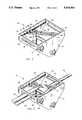
- FIG. 2is a perspective view of the multiple-ply registration apparatus of the present invention
- FIG. 3is a perspective view similar to FIG. 2, with a pair of plies of a web threaded through the invention ;
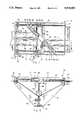
- FIG. 4is a top view of the apparatus of FIG. 3;
- FIG. 5is a sectional view taken at lines 5-5 in FIG. 4;
- FIG. 6is a view similar to FIG. 4, with a broken line drawing of an adjustment to the apparatus.
- FIG. 7is a view similar to FIG. 5, showing adjustment of the idler roller.
- FIG. 1a pictorial diagram of the sequence of events in producing a multiple-ply web is depicted. Beginning at the left hand portion of the Figure, a continuous web 10 with a lower liner 12 is provided, the liner 12 being pulled away from the web 10 as web 10 enters a back printing station identified generally at 14. Back printing station 14 will print on the lower surface of web 10 as desired. After exiting back printing station 14, liner 12 is reapplied to web 10 and the combined web enters a face printing station 16.
- Face printing station 16will print at least two longitudinal rows of labels, one row of labels identified generally at 18 and a second row of labels identified generally at 20.
- Web 10is then split into two separate webs by a cutter 22.
- a circular blade(not shown) splits web 10 into a first web 24 which has the first row of labels 18 thereon, and a second web 26 which has the second row of labels 20 thereon.
- the liner 12is removed from first web 24 and rolled on a reel 28 prior to the introduction of first and second webs 24 and 26 into the multiple-ply web registration apparatus 30 of the present invention.
- the apparatus 30 of the present inventionwill register labels 18 on first web 24 directly on top of labels 20 on second web 26 to produce a multiple-ply web identified generally as 32.
- the excess portion of first web 24 surrounding labels 18is then removed and stored on a reel 34.
- the web 32 with multiple-ply labels thereonis then stored on a reel 36 or individually sheeted and collected.
- the multiple-ply web registration apparatus 30 of the present inventionincludes a forward panel 38 and opposing rearward panel 40 separated by a pair of generally triangular shaped side panels 42 and 44.
- the lower ends of side panels 42 and 44are connected by a bottom plate 46 to form a rigid three dimensional structure.
- a slot 48 in forward panel 38will receive first and second webs 24 and 26 as they enter the apparatus 30.
- a slot 50 in rearward panel 40will receive multiple-ply web 32 as it exists the apparatus 30.
- a threaded shaft 52is rotatably mounted between forward and rearward panels 38 and 40 adjacent and parallel to side panel 42.
- a similar threaded shaft 54is mounted parallel to shaft 52 and adjacent side panel 44.
- a drive shaft 56is mounted transversely between side panels 42 and 44 parallel and adjacent to forward panel 38, immediately under threaded shafts 52 and 54.
- a pair of gear sets 58are mounted at each end of drive shaft 56 to directly interconnect drive shaft 56 with threaded shafts 52 and 54, so as to directly transmit the rotational movement of the drive shaft to the threaded shafts.
- Drive shaft 56protrudes through side panel 44, and a handle 60 is connected thereto to permit manual rotation of the drive shaft.
- An idler roller 62is freely rotatable on drive shaft 56, and supports first and second webs 24 and 26 as they enter the apparatus 30.
- a first cylindrical turning bar 64is mounted between a pair of support blocks 66 which are affixed to side panels 42 and 44 respectively, such that first turning bar 64 is oriented at a 45° angle
- An aperture 68 in each support blockreceives threaded rods 52 and 54 and permits free rotation thereof through the support block 66.
- a second cylindrical turning bar 70is mounted between a support block 72 and a support block 74.
- Support block 72has an aperture 76 which is interiorly threaded to correspond with threaded shaft 52
- support block 74has an aperture 78 which is interiorly threaded to correspond with the threads on threaded shaft 54.
- Second turning bar 70is mounted parallel to first turning bar 64, with support blocks 72 and 74 engaging threaded shafts 52 and 54 to move forwardly and rearwardly upon rotation of the threaded shafts 52 and 54.
- An adjustable idler roller 80is rotatably mounted at each end to a pair of vertical threaded rods 82 and 84.
- Idler rolleris oriented transversely between side panels 42 and 44, perpendicular to the direction of travel of webs 24 and 26.
- Vertical threaded rods 82 and 84are mounted between pairs of upper and lower bearings 86 to permit rotation of threaded rods 82 and 84.
- Idler roller 80is rotatably supported on blocks 88, which are threaded to engage threaded rods 82 and 84. Thus, rotation of threaded rods 82 and 84 will cause idler roller 80 to move upwardly or downwardly within apparatus 30.
- a drive shaft 90extends between side panels 42 and 44 adjacent the lower ends of vertical threaded rods 82 and 84, and has gear sets 92 mounted at each end to engage vertical threaded rods 82 and 84. Thus, rotation of drive shaft 90 will simultaneously rotate threaded rods 82 and 84 to raise and lower idler roller 80.
- Drive shaft 90extends through side panel 44, and has a handle 94 connected thereto to permit manual rotation of the drive shaft.
- FIGS. 5 and 6depict the adjustability of the present invention to provide accurate registration of the first web 24 on top of second web 26.
- FIG. 6shows that movement of second turning bar 70 forward and away from first turning bar 64 will shift first web 24 transversely with respect to second web 26, as shown by arrow 96.
- the broken line position of first turning baris indicated at 70', and is positioned forwardly, farther away from second turning bar 64 than the solid line first turning bar 70. It can be seen that this movement will shift web 24 laterally with respect to web 26 as shown by the broken line indication of first web designated at 24'. Movement of turning bar 70 towards second turning bar 64 would shift first web 24' in the opposite lateral direction.
- various widths of webs as well as various separations between the websmay be easily and accurately registered in the lateral direction by movement of first turning bar 70.
- first web 24will have a longer distance to travel between front panel 38 and rear panel 40 then will second web 26.
- idler roller 80This downward movement of idler roller 80 lengthens the distance which web 26' will travel, and thereby adjust the longitudinal location of labels 20 with respect to labels 18 on first web 24. Adjustment of idler roller 80 coincides with adjustment of first turning bar 70 to accurately register webs 24 and 26 to perfectly align labels 18 on top of labels 20 to create multiple-ply web 32.
Landscapes
- Folding Of Thin Sheet-Like Materials, Special Discharging Devices, And Others (AREA)
Abstract
Description
Claims (3)
Priority Applications (1)
| Application Number | Priority Date | Filing Date | Title |
|---|---|---|---|
| US07/574,270US5016801A (en) | 1990-08-28 | 1990-08-28 | Multiple-ply web registration apparatus |
Applications Claiming Priority (1)
| Application Number | Priority Date | Filing Date | Title |
|---|---|---|---|
| US07/574,270US5016801A (en) | 1990-08-28 | 1990-08-28 | Multiple-ply web registration apparatus |
Publications (1)
| Publication Number | Publication Date |
|---|---|
| US5016801Atrue US5016801A (en) | 1991-05-21 |
Family
ID=24295396
Family Applications (1)
| Application Number | Title | Priority Date | Filing Date |
|---|---|---|---|
| US07/574,270Expired - Fee RelatedUS5016801A (en) | 1990-08-28 | 1990-08-28 | Multiple-ply web registration apparatus |
Country Status (1)
| Country | Link |
|---|---|
| US (1) | US5016801A (en) |
Cited By (40)
| Publication number | Priority date | Publication date | Assignee | Title |
|---|---|---|---|---|
| US5100117A (en)* | 1990-04-26 | 1992-03-31 | Man Roland Druckmaschinen Ag | Web guiding system, particularly turning bar system for superposing slit paper webs received from a web-fed rotary printing machine |
| US5348278A (en)* | 1993-02-16 | 1994-09-20 | Moore Business Forms, Inc. | Paper web separator and guiding apparatus |
| US5413039A (en)* | 1992-07-22 | 1995-05-09 | Tokyo Kikai Seisakusho, Ltd. | Rotary press and feeder unit for the same |
| US5464143A (en)* | 1993-04-08 | 1995-11-07 | Hansen; Robert E. | Width adjustable angle bar assembly for a printing press |
| US5520317A (en)* | 1993-04-07 | 1996-05-28 | Koenig & Bauer Aktiengesellschaft | Turning bar with selectively openable air discharge openings |
| EP0808789A1 (en)* | 1996-05-23 | 1997-11-26 | BIELOMATIK LEUZE GmbH + Co. | Device for guiding multi-ply webs of paper or the like |
| US5806746A (en)* | 1996-10-18 | 1998-09-15 | Pitney Bowes Inc. | Method and apparatus for guiding webs in a web handling system |
| US5860616A (en)* | 1997-03-07 | 1999-01-19 | Energy Saving Products And Sales Corporation | Alternative feeding from roll or box into laser printer |
| WO1999015450A1 (en)* | 1997-09-23 | 1999-04-01 | Moore U.S.A., Inc. | Dual web singulating cutter |
| EP0909834A3 (en)* | 1997-09-11 | 1999-05-19 | Leybold Systems GmbH | Foil transporting device |
| WO2000006478A1 (en)* | 1998-07-29 | 2000-02-10 | Clopay Plastic Products Company, Inc. | In-line web separator |
| WO2000018674A1 (en)* | 1998-09-29 | 2000-04-06 | Schober Gmbh Werkzeug- Und Maschinenbau | Device for producing storage cases, e.g. for diskettes, cds or similar |
| US20030075640A1 (en)* | 2000-03-22 | 2003-04-24 | Anton Weis | Angle bar assembly method for deviating a material web |
| US6571673B2 (en)* | 2000-08-10 | 2003-06-03 | Sig Alfa S.P.A | Method and apparatus for adjusting the inclination of the label in a labeling machine for conical or non-cylindrical containers |
| US6575399B1 (en)* | 2000-01-19 | 2003-06-10 | Energy Savings Products And Sales Corp. | Web control matrix |
| US20030164103A1 (en)* | 2002-03-01 | 2003-09-04 | Lamothe Richard P. | Apparatus for slitting, merging, and cutting a continuous paperweb |
| US6736350B2 (en) | 2001-10-25 | 2004-05-18 | Energy Saving Products And Sales Corp. | Web control matrix with selectable web orientation |
| US20040164477A1 (en)* | 2003-02-25 | 2004-08-26 | Daniel Buri | Device for deflecting a web |
| WO2005028187A1 (en)* | 2003-09-12 | 2005-03-31 | Windmöller & Hölscher Kg | Film turning station |
| US20050194088A1 (en)* | 2004-03-02 | 2005-09-08 | Kohler Herbert B. | Method and apparatus for making corrugated cardboard |
| US20050194103A1 (en)* | 2004-03-02 | 2005-09-08 | Kohler Herbert B. | Corrugator glue machine having web tension nulling mechanism |
| EP1588969A1 (en)* | 2004-04-23 | 2005-10-26 | Bobst Sa | Apparatus for transfer of strip-like material between an external and an internal medium of a machine |
| US20050236513A1 (en)* | 2004-04-23 | 2005-10-27 | Michel Piguet | Device for transferring a foil matter from outside to inside of a machine |
| WO2006103487A1 (en)* | 2005-03-29 | 2006-10-05 | Concepts For Succes | Web handling process and equipment |
| US20060225830A1 (en)* | 2005-04-12 | 2006-10-12 | Kohler Herbert B | Method and apparatus for producing a corrugated product |
| FR2887864A1 (en)* | 2005-07-01 | 2007-01-05 | Sarl Additif Sarl | DEVICE FOR SUPPLYING A MACHINE FROM A COIL, COIL AND METHOD OF REWINDING SUCH A COIL |
| US20070098887A1 (en)* | 2005-10-27 | 2007-05-03 | Kohler Herbert B | Method for producing corrugated cardboard |
| US20080029640A1 (en)* | 2006-07-31 | 2008-02-07 | Industrial Technology Research Institute | Apparatus and system for roll-to-roll processing |
| US20080317940A1 (en)* | 2007-06-20 | 2008-12-25 | Kohler Herbert B | Method for Producing Corrugated Cardboard |
| DE102008002054A1 (en)* | 2008-05-28 | 2009-12-03 | Koenig & Bauer Aktiengesellschaft | Turning bar module for e.g. web-fed rotary printing machine, has carriage driven by threaded spindle, bar fastened to carriage, and guide provided for carriage, where module with all components is removed from printing machine as unit |
| US20100059567A1 (en)* | 2008-09-09 | 2010-03-11 | Hewlett-Packard Development Company, L.P. | Turn-bar |
| RU2394746C2 (en)* | 2005-03-29 | 2010-07-20 | Консептс Фо Саксес | Method for web treatment and treatment machine for web treatment |
| US20100181015A1 (en)* | 2009-01-22 | 2010-07-22 | Kohler Herbert B | Method for moisture and temperature control in corrugating operation |
| US20100331160A1 (en)* | 2008-03-21 | 2010-12-30 | Kohler Herbert B | Apparatus for producing corrugated board |
| US20110064507A1 (en)* | 2009-09-16 | 2011-03-17 | Xerox Corporation | Media Inversion System for A Continuous Web Printer |
| US20120035039A1 (en)* | 2010-08-04 | 2012-02-09 | Goss International Americas, Inc. | Web guiding apparatus |
| US8771579B2 (en) | 2012-11-01 | 2014-07-08 | Hbk Family, Llc | Method and apparatus for fluting a web in the machine direction |
| CN112009782A (en)* | 2020-09-30 | 2020-12-01 | 东莞成丰包装机械有限公司 | Spacing adjustment structure for conveying of multi-row bag packaging equipment |
| CN112009807A (en)* | 2020-09-30 | 2020-12-01 | 东莞成丰包装机械有限公司 | Multi-column strip-shaped bag-in-bag packaging machine with automatic alignment of inner bag and outer bag |
| US11118314B2 (en) | 2019-08-05 | 2021-09-14 | Intpro, Llc | Paper-specific moisture control in a traveling paper web |
Citations (4)
| Publication number | Priority date | Publication date | Assignee | Title |
|---|---|---|---|---|
| US2284318A (en)* | 1939-11-15 | 1942-05-26 | Cleveland Shopping News Compan | Universal web guide |
| US3103843A (en)* | 1958-07-02 | 1963-09-17 | Donnelley & Sons Co | Web feed apparatus for a case forming machine for books |
| US3399884A (en)* | 1966-03-15 | 1968-09-03 | Procter & Gamble | Method and apparatus for combining webs |
| US3809303A (en)* | 1969-05-02 | 1974-05-07 | Wifag Maschf | Device for guiding printed paper webs from a printing machine |
- 1990
- 1990-08-28USUS07/574,270patent/US5016801A/ennot_activeExpired - Fee Related
Patent Citations (4)
| Publication number | Priority date | Publication date | Assignee | Title |
|---|---|---|---|---|
| US2284318A (en)* | 1939-11-15 | 1942-05-26 | Cleveland Shopping News Compan | Universal web guide |
| US3103843A (en)* | 1958-07-02 | 1963-09-17 | Donnelley & Sons Co | Web feed apparatus for a case forming machine for books |
| US3399884A (en)* | 1966-03-15 | 1968-09-03 | Procter & Gamble | Method and apparatus for combining webs |
| US3809303A (en)* | 1969-05-02 | 1974-05-07 | Wifag Maschf | Device for guiding printed paper webs from a printing machine |
Cited By (76)
| Publication number | Priority date | Publication date | Assignee | Title |
|---|---|---|---|---|
| US5100117A (en)* | 1990-04-26 | 1992-03-31 | Man Roland Druckmaschinen Ag | Web guiding system, particularly turning bar system for superposing slit paper webs received from a web-fed rotary printing machine |
| US5413039A (en)* | 1992-07-22 | 1995-05-09 | Tokyo Kikai Seisakusho, Ltd. | Rotary press and feeder unit for the same |
| US5348278A (en)* | 1993-02-16 | 1994-09-20 | Moore Business Forms, Inc. | Paper web separator and guiding apparatus |
| US5374042A (en)* | 1993-02-16 | 1994-12-20 | Moore Business Forms, Inc. | Paper web separator and deflector |
| US5520317A (en)* | 1993-04-07 | 1996-05-28 | Koenig & Bauer Aktiengesellschaft | Turning bar with selectively openable air discharge openings |
| US5464143A (en)* | 1993-04-08 | 1995-11-07 | Hansen; Robert E. | Width adjustable angle bar assembly for a printing press |
| US5823464A (en)* | 1996-05-23 | 1998-10-20 | Bielomatik Leuze Gmbh & Co. | Device for guiding ply webs of paper or the like |
| EP0808789A1 (en)* | 1996-05-23 | 1997-11-26 | BIELOMATIK LEUZE GmbH + Co. | Device for guiding multi-ply webs of paper or the like |
| US5806746A (en)* | 1996-10-18 | 1998-09-15 | Pitney Bowes Inc. | Method and apparatus for guiding webs in a web handling system |
| US5860616A (en)* | 1997-03-07 | 1999-01-19 | Energy Saving Products And Sales Corporation | Alternative feeding from roll or box into laser printer |
| EP0909834A3 (en)* | 1997-09-11 | 1999-05-19 | Leybold Systems GmbH | Foil transporting device |
| WO1999015450A1 (en)* | 1997-09-23 | 1999-04-01 | Moore U.S.A., Inc. | Dual web singulating cutter |
| US5953971A (en)* | 1997-09-23 | 1999-09-21 | Moore U.S.A., Inc. | Dual web singulating cutter |
| US6125730A (en)* | 1997-09-23 | 2000-10-03 | Moore U.S.A. Inc. | Dual web singulating cutter |
| WO2000006478A1 (en)* | 1998-07-29 | 2000-02-10 | Clopay Plastic Products Company, Inc. | In-line web separator |
| WO2000018674A1 (en)* | 1998-09-29 | 2000-04-06 | Schober Gmbh Werkzeug- Und Maschinenbau | Device for producing storage cases, e.g. for diskettes, cds or similar |
| US6575399B1 (en)* | 2000-01-19 | 2003-06-10 | Energy Savings Products And Sales Corp. | Web control matrix |
| US20030075640A1 (en)* | 2000-03-22 | 2003-04-24 | Anton Weis | Angle bar assembly method for deviating a material web |
| US6820839B2 (en)* | 2000-03-22 | 2004-11-23 | Koenig & Bauer Aktiengesellschaft | Angle bar assembly method for deviating a material web |
| US6571673B2 (en)* | 2000-08-10 | 2003-06-03 | Sig Alfa S.P.A | Method and apparatus for adjusting the inclination of the label in a labeling machine for conical or non-cylindrical containers |
| US6736350B2 (en) | 2001-10-25 | 2004-05-18 | Energy Saving Products And Sales Corp. | Web control matrix with selectable web orientation |
| US20030164103A1 (en)* | 2002-03-01 | 2003-09-04 | Lamothe Richard P. | Apparatus for slitting, merging, and cutting a continuous paperweb |
| US6994005B2 (en)* | 2002-03-01 | 2006-02-07 | Energy Saving Products And Sales Corp. | Apparatus for slitting, merging, and cutting a continuous paperweb |
| US20040164477A1 (en)* | 2003-02-25 | 2004-08-26 | Daniel Buri | Device for deflecting a web |
| US7201300B2 (en)* | 2003-02-25 | 2007-04-10 | Wifag Machinenfabrik | Device for deflecting a web |
| US20070065529A1 (en)* | 2003-09-12 | 2007-03-22 | Gerd Kasselmann | Film turning station |
| WO2005028187A1 (en)* | 2003-09-12 | 2005-03-31 | Windmöller & Hölscher Kg | Film turning station |
| US7717148B2 (en) | 2004-03-02 | 2010-05-18 | Kohler Herbert B | Machine having web tension nulling mechanism |
| US20050194103A1 (en)* | 2004-03-02 | 2005-09-08 | Kohler Herbert B. | Corrugator glue machine having web tension nulling mechanism |
| US20050194088A1 (en)* | 2004-03-02 | 2005-09-08 | Kohler Herbert B. | Method and apparatus for making corrugated cardboard |
| US20070261793A1 (en)* | 2004-03-02 | 2007-11-15 | Kohler Herbert B | Machine having web tension nulling mechanism |
| US7267153B2 (en) | 2004-03-02 | 2007-09-11 | Herbert B Kohler | Corrugator glue machine having web tension nulling mechanism |
| US7347398B2 (en) | 2004-04-23 | 2008-03-25 | Bobst S.A. | Device for transferring a foil matter from outside to inside of a machine |
| EP1588969A1 (en)* | 2004-04-23 | 2005-10-26 | Bobst Sa | Apparatus for transfer of strip-like material between an external and an internal medium of a machine |
| US20050236513A1 (en)* | 2004-04-23 | 2005-10-27 | Michel Piguet | Device for transferring a foil matter from outside to inside of a machine |
| WO2006103487A1 (en)* | 2005-03-29 | 2006-10-05 | Concepts For Succes | Web handling process and equipment |
| US7780156B2 (en) | 2005-03-29 | 2010-08-24 | Christoph Schmitz | Web handling process and equipment |
| US20080197164A1 (en)* | 2005-03-29 | 2008-08-21 | Christoph Schmitz | Web Hadling Process and Equipment |
| RU2394746C2 (en)* | 2005-03-29 | 2010-07-20 | Консептс Фо Саксес | Method for web treatment and treatment machine for web treatment |
| US8057621B2 (en) | 2005-04-12 | 2011-11-15 | Kohler Herbert B | Apparatus and method for producing a corrugated product under ambient temperature conditions |
| US20110011522A1 (en)* | 2005-04-12 | 2011-01-20 | Kohler Herbert B | Method and apparatus for producing a corrugated product |
| US20060225830A1 (en)* | 2005-04-12 | 2006-10-12 | Kohler Herbert B | Method and apparatus for producing a corrugated product |
| FR2887864A1 (en)* | 2005-07-01 | 2007-01-05 | Sarl Additif Sarl | DEVICE FOR SUPPLYING A MACHINE FROM A COIL, COIL AND METHOD OF REWINDING SUCH A COIL |
| WO2007003844A3 (en)* | 2005-07-01 | 2007-06-07 | Sarl Additif Sarl | Device for feeding a web of a machine off of a spool |
| US7595086B2 (en) | 2005-10-27 | 2009-09-29 | Kohler Herbert B | Method for producing corrugated cardboard |
| US20070098887A1 (en)* | 2005-10-27 | 2007-05-03 | Kohler Herbert B | Method for producing corrugated cardboard |
| US20080029640A1 (en)* | 2006-07-31 | 2008-02-07 | Industrial Technology Research Institute | Apparatus and system for roll-to-roll processing |
| US7926758B2 (en)* | 2006-07-31 | 2011-04-19 | Industrial Technology Research Institute | Apparatus and system for roll-to-roll processing |
| US20080317940A1 (en)* | 2007-06-20 | 2008-12-25 | Kohler Herbert B | Method for Producing Corrugated Cardboard |
| US8672825B2 (en) | 2008-03-21 | 2014-03-18 | Hbk Family, Llc | Apparatus for producing corrugated board |
| US11260616B2 (en) | 2008-03-21 | 2022-03-01 | Hbk Family, Llc | Method for producing corrugated board |
| US10543654B2 (en) | 2008-03-21 | 2020-01-28 | Hbk Family, Llc | Method for producing corrugated board |
| US20100331160A1 (en)* | 2008-03-21 | 2010-12-30 | Kohler Herbert B | Apparatus for producing corrugated board |
| US9649821B2 (en) | 2008-03-21 | 2017-05-16 | Hbk Family, Llc | Apparatus for producing corrugated board |
| DE102008002054A1 (en)* | 2008-05-28 | 2009-12-03 | Koenig & Bauer Aktiengesellschaft | Turning bar module for e.g. web-fed rotary printing machine, has carriage driven by threaded spindle, bar fastened to carriage, and guide provided for carriage, where module with all components is removed from printing machine as unit |
| DE102008002054B4 (en)* | 2008-05-28 | 2014-08-14 | Koenig & Bauer Aktiengesellschaft | Turning bar module |
| US8684298B2 (en)* | 2008-09-09 | 2014-04-01 | Hewlett-Packard Development Company, L.P. | Turn-bar |
| US20100059567A1 (en)* | 2008-09-09 | 2010-03-11 | Hewlett-Packard Development Company, L.P. | Turn-bar |
| US8398802B2 (en) | 2009-01-22 | 2013-03-19 | Coater Services, Inc. | Method for moisture and temperature control in corrugating operation |
| US20100181015A1 (en)* | 2009-01-22 | 2010-07-22 | Kohler Herbert B | Method for moisture and temperature control in corrugating operation |
| US8316766B2 (en)* | 2009-09-16 | 2012-11-27 | Xerox Corporation | Media inversion system for a continuous web printer |
| US8646385B2 (en) | 2009-09-16 | 2014-02-11 | Xerox Corporation | Media inversion system for a continuous web printer |
| US20110064507A1 (en)* | 2009-09-16 | 2011-03-17 | Xerox Corporation | Media Inversion System for A Continuous Web Printer |
| US8235372B2 (en)* | 2010-08-04 | 2012-08-07 | Goss International Americas, Inc. | Web guiding apparatus |
| US20120035039A1 (en)* | 2010-08-04 | 2012-02-09 | Goss International Americas, Inc. | Web guiding apparatus |
| US9981441B2 (en) | 2012-11-01 | 2018-05-29 | Hbk Family, Llc | Method and apparatus for fluting a web in the machine direction |
| US10479043B2 (en) | 2012-11-01 | 2019-11-19 | Hbk Family, Llc | Method and apparatus for fluting a web in the machine direction |
| US9346236B2 (en) | 2012-11-01 | 2016-05-24 | Hbk Family Llc | Method and apparatus for fluting a web in the machine direction |
| US10882270B2 (en) | 2012-11-01 | 2021-01-05 | Hbk Family, Llc | Apparatus for fluting a web in the machine direction |
| US8771579B2 (en) | 2012-11-01 | 2014-07-08 | Hbk Family, Llc | Method and apparatus for fluting a web in the machine direction |
| US11318701B2 (en) | 2012-11-01 | 2022-05-03 | International Paper Company | Method and apparatus for fluting a web in the machine direction |
| US11118314B2 (en) | 2019-08-05 | 2021-09-14 | Intpro, Llc | Paper-specific moisture control in a traveling paper web |
| US11162226B2 (en) | 2019-08-05 | 2021-11-02 | Intpro, Llc | Paper-specific moisture control in a traveling paper web |
| US11459704B2 (en) | 2019-08-05 | 2022-10-04 | Intpro, Llc | Paper-specific moisture control in a traveling paper web |
| CN112009782A (en)* | 2020-09-30 | 2020-12-01 | 东莞成丰包装机械有限公司 | Spacing adjustment structure for conveying of multi-row bag packaging equipment |
| CN112009807A (en)* | 2020-09-30 | 2020-12-01 | 东莞成丰包装机械有限公司 | Multi-column strip-shaped bag-in-bag packaging machine with automatic alignment of inner bag and outer bag |
Similar Documents
| Publication | Publication Date | Title |
|---|---|---|
| US5016801A (en) | Multiple-ply web registration apparatus | |
| DE69417877T2 (en) | METHOD FOR REMOVING LABELS WITHOUT COVER TAPE | |
| EP0710558B1 (en) | Rotary web printing press | |
| DE2533566C3 (en) | Web-shaped intermediate image carrier and method and device for its production | |
| DE69929568T2 (en) | Method and device for controlling a web transport at the print start time | |
| SE438986B (en) | PLANT FOR MANUFACTURE OF PRESSURE WELL PAPER COAT | |
| EP0060450B1 (en) | Device for splicing the trailing end of a web drawn off a consumed roll to the leading end of a web drawn off a new roll | |
| DE3022525C2 (en) | Method and device for applying a sticker to an endless web | |
| DE3713666C2 (en) | Embossing method and embossing rotary machine | |
| DE3442627C2 (en) | ||
| US2809582A (en) | Machine and method for processing webs of paper base and similar materials | |
| EP0533042A1 (en) | Device for threading webs in rotary web printing machines | |
| DE2909348C2 (en) | ||
| DE2843361C2 (en) | ||
| DE3519595A1 (en) | CONNECTING DEVICE FOR CARRIER STRIPS FITTED WITH ADHESIVE LABELS | |
| US4438696A (en) | Multi-purpose flexographic press module | |
| DE69228328T2 (en) | Cutting-punching device for a printing device | |
| DE719833C (en) | Paper web conveyor device, especially for cutting and folding units of printing machines | |
| EP0908310B1 (en) | Web drive on top of a folding apparatus | |
| DE2509276A1 (en) | Sheet positioner for rotary printing machine - has shaft with guide rollers for transport belts moving perpendicular to sheets | |
| DE3152781A1 (en) | HIGH-SPEED PRINTER WITH SEVERAL PAPER PATHS | |
| DE2508041A1 (en) | UNCOOLING DRUM WITH VARIABLE SPEED | |
| US2800325A (en) | Apparatus for the assembly and finishing of sets of duplicating forms | |
| US4491309A (en) | Conveyor for directing ribbons away from a printing press operating at walk speed | |
| DE2605773A1 (en) | Multi web rotary print machine with single track dryer - dispenses powder between webs entering dryer to avoid smudging |
Legal Events
| Date | Code | Title | Description |
|---|---|---|---|
| AS | Assignment | Owner name:INDUSTRIAL LABEL CORPORATION, A CORP OF NE, NEBRAS Free format text:ASSIGNMENT OF ASSIGNORS INTEREST.;ASSIGNORS:GILAT, RONEN;BOYD, DAVID B.;REEL/FRAME:005483/0472 Effective date:19900822 | |
| FPAY | Fee payment | Year of fee payment:4 | |
| REMI | Maintenance fee reminder mailed | ||
| FPAY | Fee payment | Year of fee payment:8 | |
| SULP | Surcharge for late payment | ||
| LAPS | Lapse for failure to pay maintenance fees | ||
| STCH | Information on status: patent discontinuation | Free format text:PATENT EXPIRED DUE TO NONPAYMENT OF MAINTENANCE FEES UNDER 37 CFR 1.362 | |
| FP | Lapsed due to failure to pay maintenance fee | Effective date:20030521 | |
| AS | Assignment | Owner name:HARRIS N.A., AS AGENT, ILLINOIS Free format text:SECURITY AGREEMENT;ASSIGNOR:LABEL ACQUISITION CORPORATION;REEL/FRAME:017314/0850 Effective date:20060317 | |
| AS | Assignment | Owner name:LABEL ACQUISITION CORPORATION, IDAHO Free format text:RELEASE BY SECURED PARTY;ASSIGNOR:HARRIS N.A., AS AGENT;REEL/FRAME:021291/0528 Effective date:20070404 | |
| AS | Assignment | Owner name:BANK OF AMERICA, N.A., AS ADMINISTRATIVE AGENT, IL Free format text:NOTICE OF SECURITY INTEREST IN PATENTS;ASSIGNOR:INDUSTRIAL LABEL CORPORATION;REEL/FRAME:027092/0434 Effective date:20111003 |