US5016489A - Multiarticulation robot - Google Patents
Multiarticulation robotDownload PDFInfo
- Publication number
- US5016489A US5016489AUS07/425,576US42557689AUS5016489AUS 5016489 AUS5016489 AUS 5016489AUS 42557689 AUS42557689 AUS 42557689AUS 5016489 AUS5016489 AUS 5016489A
- Authority
- US
- United States
- Prior art keywords
- arm
- rocking
- shaft
- rotary
- articulation mechanism
- Prior art date
- Legal status (The legal status is an assumption and is not a legal conclusion. Google has not performed a legal analysis and makes no representation as to the accuracy of the status listed.)
- Expired - Fee Related
Links
- 230000007246mechanismEffects0.000claimsabstractdescription38
- 239000011435rockSubstances0.000claims2
- NJPPVKZQTLUDBO-UHFFFAOYSA-NnovaluronChemical compoundC1=C(Cl)C(OC(F)(F)C(OC(F)(F)F)F)=CC=C1NC(=O)NC(=O)C1=C(F)C=CC=C1FNJPPVKZQTLUDBO-UHFFFAOYSA-N0.000description2
- 238000010276constructionMethods0.000description1
- 238000003466weldingMethods0.000description1
Images

Classifications
- B—PERFORMING OPERATIONS; TRANSPORTING
- B25—HAND TOOLS; PORTABLE POWER-DRIVEN TOOLS; MANIPULATORS
- B25J—MANIPULATORS; CHAMBERS PROVIDED WITH MANIPULATION DEVICES
- B25J9/00—Programme-controlled manipulators
- B25J9/10—Programme-controlled manipulators characterised by positioning means for manipulator elements
- B25J9/1005—Programme-controlled manipulators characterised by positioning means for manipulator elements comprising adjusting means
- B25J9/1015—Programme-controlled manipulators characterised by positioning means for manipulator elements comprising adjusting means using additional, e.g. microadjustment of the end effector
- B—PERFORMING OPERATIONS; TRANSPORTING
- B25—HAND TOOLS; PORTABLE POWER-DRIVEN TOOLS; MANIPULATORS
- B25J—MANIPULATORS; CHAMBERS PROVIDED WITH MANIPULATION DEVICES
- B25J9/00—Programme-controlled manipulators
- B25J9/02—Programme-controlled manipulators characterised by movement of the arms, e.g. cartesian coordinate type
- B25J9/04—Programme-controlled manipulators characterised by movement of the arms, e.g. cartesian coordinate type by rotating at least one arm, excluding the head movement itself, e.g. cylindrical coordinate type or polar coordinate type
- B25J9/046—Revolute coordinate type
- Y—GENERAL TAGGING OF NEW TECHNOLOGICAL DEVELOPMENTS; GENERAL TAGGING OF CROSS-SECTIONAL TECHNOLOGIES SPANNING OVER SEVERAL SECTIONS OF THE IPC; TECHNICAL SUBJECTS COVERED BY FORMER USPC CROSS-REFERENCE ART COLLECTIONS [XRACs] AND DIGESTS
- Y10—TECHNICAL SUBJECTS COVERED BY FORMER USPC
- Y10T—TECHNICAL SUBJECTS COVERED BY FORMER US CLASSIFICATION
- Y10T74/00—Machine element or mechanism
- Y10T74/20—Control lever and linkage systems
- Y10T74/20207—Multiple controlling elements for single controlled element
- Y10T74/20305—Robotic arm
- Y10T74/20317—Robotic arm including electric motor
Definitions
- This inventionrelates to a multiarticulation robot which can enter and repair an existing structure or building and which can be extended to reach a high place.
- the arms forming the respective structural partshave been large and heavy. As it is necessary to simultaneously drive the respective arms, a plurality of large servomotors or the like as well as a large controlling electric power source are required. Therefore, the price of the robot itself is very high.
- a multiarticulation robothaving a wide vertical and horizontal operating range, is simplified by making the respective parts separately driven. Consequently, the controlling electric power source to drive each part is small, avoiding the need for large, expensive servomotors, and enables the construction and operation of the robot to be inexpensive and economical.
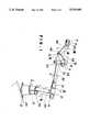
- FIG. 1is a general perspective view of one embodiment.
- FIG. 2is a general perspective view of another embodiment.
- the multiarticulation robotcomprises a pedestal 2, providing a base fixed on the floor 1 in an existing structure or building.
- a stand 3which is rotatable in the directions indicated by the double arrow II by a first rotary articulation mechanism 20.
- a first vertical arm 30is pivoted at one end at the top of the stand 3 and is inclinable in the directions indicated by the double arrow III by a first rocking articulation mechanism 40.
- a second rocking articulation mechanism 41provided at the tip of the first vertical arms 30, pivotally supports a second rotary articulation mechanism from which extends a second vertical arm 31.
- the second rocking articulation mechanism 21 and the second vertical arm 31are movable jointly in the directions indicated by the double arrow IV.
- a third vertical arm 32having a first rotary shaft 10 mounted at its outer end, is provided to extend the second vertical arm 31 and is rotatable in the directions indicated by the double arrow V by the second rotary articulation mechanism 21.
- the third vertical arm 32is provided at its tip with a first rotary shaft 10 driven by a third rotary articulation mechanism 22 to rotate the first rotary shaft 10 in the directions indicated by the double arrow VI .
- a sleeve 11, mounted at the tip of the first rotary shaft 10journals a second rotary shaft 12 movable by a third rotary articulation mechanism 23.
- Fixed at the end of the second rotary shaft 12is a fourth vertical arm 33 which is thus pivotal in the directions indicated by the double arrow VII.
- the fourth vertical arm 33is provided at its tip 13 with a fifth vertical arm 34 pivotal in the directions indicated by the double arrow VIII by a third rocking articulation mechanism 42.
- a fifth rotary articulation mechanism 24is journalled at the tip of the arm 34.
- Extending from the arm 34is a third rotary shaft 14 rotatable in the directions indicated by the double arrow VIII.
- Fixed to the third rotary shaft 14is a fixture 4, comprising itself a work tool or an attachment to which the work tool may be secured and which can be operated to move vertically and horizontally to cooperative functioning of the arms and mechanisms described.
- FIG. 2shows another embodiment of a multiarticulation robot of the present invention.
- the same reference numerals as in FIG. 1represent the same members.
- a sixth rotary articulation mechanism 25is fixed at right angles to the third rotary shaft 14 and is rotatable in the directions indicated by the double arrow V.
- the working attachment 4is fixed to the mechanism 26 to effect the selected work.
- the attachment 4 for performing such work as welding or grindingis fitted to the third rotary shaft 14 or to the sixth rotary articulation mechanism 25 (FIG. 2).
- the attachment 4can be placed in space at any cubic angle to the ground. Thereafter, the working attachment 4 is rotated and controlled at the tip of the fifth vertical arm 34 through the fOurth vertical arm 33 fixed to the second rotary shaft 12 and third rocking articulation mechanism 42.
- the present inventionis formed of a plurality of separately actuated rotary articulation mechanisms, rocking articulation mechanisms, rotary shafts, and vertical rods so that the working attachment 4 may be freely moved by selective synchronism of these mechanisms tO any predetermined position as described. That is to say, even within a wide and complicated space in which pillars, girders, and beams are interposed, the rotary articulation mechanisms, rocking articulation mechanisms, and rotary shafts are not simultaneously operated but are sequentially operated to be able to move the robot to any necessary position.
Landscapes
- Engineering & Computer Science (AREA)
- Robotics (AREA)
- Mechanical Engineering (AREA)
- Manipulator (AREA)
Abstract
Description
This invention relates to a multiarticulation robot which can enter and repair an existing structure or building and which can be extended to reach a high place.
Existing structures are usually encumbered by wide and complicated spaces in which pillars, girders, and beams are interposed from below ground up to the ceiling.
It has been conventional to employ robots, which are large and heavy in their respective structural parts but which have few extending arms, to work within such wide spaces. Such conventional robots have been so limited in the vertical and horizontal operating ranges that they require frequent relocation as a whole within the space of the structure or building. This is disadvantageous as such movement requires delicate handling least the robot be harmed.
Also, in the conventional working robot, the arms forming the respective structural parts have been large and heavy. As it is necessary to simultaneously drive the respective arms, a plurality of large servomotors or the like as well as a large controlling electric power source are required. Therefore, the price of the robot itself is very high.
Further, in operation not only must the operator must be very experienced, but excessive electric power must be used for the operation to control such large structures, which results in a very high operating cost.
According to the present invention, a multiarticulation robot, having a wide vertical and horizontal operating range, is simplified by making the respective parts separately driven. Consequently, the controlling electric power source to drive each part is small, avoiding the need for large, expensive servomotors, and enables the construction and operation of the robot to be inexpensive and economical.
The drawings show embodiments of the present invention.
FIG. 1 is a general perspective view of one embodiment.
FIG. 2 is a general perspective view of another embodiment.
The embodiments of the present invention shall be explained in detail, in the following, with reference to the drawings.
In FIG. 1, the multiarticulation robot comprises apedestal 2, providing a base fixed on the floor 1 in an existing structure or building. Mounted on thepedestal 2 is astand 3 which is rotatable in the directions indicated by the double arrow II by a firstrotary articulation mechanism 20. A firstvertical arm 30 is pivoted at one end at the top of thestand 3 and is inclinable in the directions indicated by the double arrow III by a firstrocking articulation mechanism 40. A secondrocking articulation mechanism 41, provided at the tip of the firstvertical arms 30, pivotally supports a second rotary articulation mechanism from which extends a secondvertical arm 31. The secondrocking articulation mechanism 21 and the secondvertical arm 31 are movable jointly in the directions indicated by the double arrow IV.
A thirdvertical arm 32, having a firstrotary shaft 10 mounted at its outer end, is provided to extend the secondvertical arm 31 and is rotatable in the directions indicated by the double arrow V by the secondrotary articulation mechanism 21. The thirdvertical arm 32 is provided at its tip with a firstrotary shaft 10 driven by a thirdrotary articulation mechanism 22 to rotate the firstrotary shaft 10 in the directions indicated by the double arrow VI . Further, a sleeve 11, mounted at the tip of the firstrotary shaft 10, journals a secondrotary shaft 12 movable by a thirdrotary articulation mechanism 23. Fixed at the end of the secondrotary shaft 12 is a fourthvertical arm 33 which is thus pivotal in the directions indicated by the double arrow VII. The fourthvertical arm 33 is provided at itstip 13 with a fifthvertical arm 34 pivotal in the directions indicated by the double arrow VIII by a thirdrocking articulation mechanism 42. A fifthrotary articulation mechanism 24 is journalled at the tip of thearm 34. Extending from thearm 34 is a thirdrotary shaft 14 rotatable in the directions indicated by the double arrow VIII. Fixed to the thirdrotary shaft 14 is afixture 4, comprising itself a work tool or an attachment to which the work tool may be secured and which can be operated to move vertically and horizontally to cooperative functioning of the arms and mechanisms described.
FIG. 2 shows another embodiment of a multiarticulation robot of the present invention. In this figure, the same reference numerals as in FIG. 1 represent the same members. However, here a sixthrotary articulation mechanism 25 is fixed at right angles to the thirdrotary shaft 14 and is rotatable in the directions indicated by the double arrow V. Theworking attachment 4 is fixed to the mechanism 26 to effect the selected work.
As mentioned above, in the present invention theattachment 4 for performing such work as welding or grinding is fitted to the thirdrotary shaft 14 or to the sixth rotary articulation mechanism 25 (FIG. 2).
By selectively operating each of the firstrotary articulation mechanism 20, firstrocking articulation mechanism 40, secondrotary articulation mechanism 21, the secondrocking articulation mechanism 41, secondvertical arm 31, thirdvertical arm 32, thirdrotary articulation mechanism 22, and fourthrotary articulation mechanism 23, theattachment 4 can be placed in space at any cubic angle to the ground. Thereafter, the workingattachment 4 is rotated and controlled at the tip of the fifthvertical arm 34 through the fOurthvertical arm 33 fixed to the secondrotary shaft 12 and thirdrocking articulation mechanism 42.
The present invention is formed of a plurality of separately actuated rotary articulation mechanisms, rocking articulation mechanisms, rotary shafts, and vertical rods so that the workingattachment 4 may be freely moved by selective synchronism of these mechanisms tO any predetermined position as described. That is to say, even within a wide and complicated space in which pillars, girders, and beams are interposed, the rotary articulation mechanisms, rocking articulation mechanisms, and rotary shafts are not simultaneously operated but are sequentially operated to be able to move the robot to any necessary position.
Claims (3)
1. A multiarticulation robot comprising a rotatable stand; a first rotary articulation mechanism for rotating said stand; a first arm pivotally journalled on said stand; a first rocking articulation mechanism for rocking said first arm; a second arm pivotally mounted at the opposite end of said first arm; a second rocking articulation mechanism for rocking said second arm; a third arm slideably extending from said second arm; a second rotary articulation mechanism for rotting said third arm; a first shaft rotatably mounted at the end of said third arm at an axis intersecting the axis of said third arm; a third rotary articulation mechanism for rotating said first shaft; a second shaft rotatably mounted at the end of said first shaft at an axis intersecting, at right angles, said first shaft; a third rocking articulation mechanism for rocking said second shaft about an axis; a fourth arm mounted on said second shaft and conjointly rocking therewith; a third shaft mounted at the end of said fourth arm, having an axis extending transversely to the plane in which said fourth arm rocks; a fourth rocking articulation mechanism for rocking said third shaft; a fifth arm mounted at one end to said third rotary shaft and conjointly rocking therewith; a fourth rotary shaft mounted at the end of said fifth rm, having an axis extending transversely to the plane in which said fifth arm rocks; a fourth rotary articulation mechanism for rotating said fourth shaft.
2. The robot according to claim 1 including a fixed base, said rotary stand being mounted on said fixed base.
3. The robot according to claim 1, including work performing means mounted at the end of said fourth rotatable shaft.
Applications Claiming Priority (2)
| Application Number | Priority Date | Filing Date | Title |
|---|---|---|---|
| JP1988138384UJPH0261588U (en) | 1988-10-24 | 1988-10-24 | |
| JP63-138384[U] | 1988-10-24 |
Publications (1)
| Publication Number | Publication Date |
|---|---|
| US5016489Atrue US5016489A (en) | 1991-05-21 |
Family
ID=15220682
Family Applications (1)
| Application Number | Title | Priority Date | Filing Date |
|---|---|---|---|
| US07/425,576Expired - Fee RelatedUS5016489A (en) | 1988-10-24 | 1989-10-23 | Multiarticulation robot |
Country Status (3)
| Country | Link |
|---|---|
| US (1) | US5016489A (en) |
| EP (1) | EP0366430A1 (en) |
| JP (1) | JPH0261588U (en) |
Cited By (31)
| Publication number | Priority date | Publication date | Assignee | Title |
|---|---|---|---|---|
| US5098024A (en)* | 1990-07-27 | 1992-03-24 | Northrop Corporation | Spray end effector |
| US5231889A (en)* | 1991-01-31 | 1993-08-03 | Samsung Electronics Co., Ltd. | Wrist unit for industrial robot |
| US5243872A (en)* | 1990-04-30 | 1993-09-14 | Kumho & Co., Inc. | Robotic hand for controlling movement in multiple axes |
| US5265486A (en)* | 1990-09-26 | 1993-11-30 | Ammco Tools Technology Corporation | Portable external drive assembly |
| US5410944A (en)* | 1993-06-03 | 1995-05-02 | Cushman; William B. | Telescoping robot arm with spherical joints |
| EP0658405A1 (en)* | 1993-12-17 | 1995-06-21 | COMAU S.p.A. | Industrial robot with integrated reduction gear units |
| US5661387A (en)* | 1992-02-29 | 1997-08-26 | Stadele, Deceased; Erhard | Device for manipulating objects in a gripper or the like |
| US6230721B1 (en)* | 1996-10-30 | 2001-05-15 | Shibaura Mechatronics Corporation | Processing apparatus and method, robot apparatus |
| US20030045888A1 (en)* | 1998-02-24 | 2003-03-06 | Endo Via Medical, Inc. | Articulated apparatus for telemanipulator system |
| US20030167061A1 (en)* | 2000-07-01 | 2003-09-04 | Wolfgang Schlegel | Medical device for stereotaxis and patient positioning |
| US20040055456A1 (en)* | 2002-08-08 | 2004-03-25 | Hajime Kurita | Variable displacement compressor |
| US20060036264A1 (en)* | 2004-08-06 | 2006-02-16 | Sean Selover | Rigidly guided implant placement |
| USD545334S1 (en)* | 2006-05-31 | 2007-06-26 | Kraft Telebobotics, Inc. | Robotic master controller |
| US20080071291A1 (en)* | 2006-06-13 | 2008-03-20 | Intuitive Surgical, Inc. | Minimally invasive surgical system |
| FR2930472A1 (en)* | 2008-04-24 | 2009-10-30 | Univ Havre Etablissement Publi | MANIPULATOR ROBOT AND ASSOCIATED CONTROL FOR FINAL POSITIONING OF TERMINAL END |
| US20100089216A1 (en)* | 2005-08-04 | 2010-04-15 | Lintec Corporation | Sheet cutting device and cutting method |
| CN102039240A (en)* | 2010-12-31 | 2011-05-04 | 广西大学 | Spraying robot mechanism |
| US20110107866A1 (en)* | 2009-11-10 | 2011-05-12 | Kabushiki Kaisha Yaskawa Denki | Robot |
| USD638044S1 (en)* | 2010-05-24 | 2011-05-17 | Denso Corporation | Industrial robot |
| USD638043S1 (en)* | 2010-05-24 | 2011-05-17 | Denso Corporation | Industrial robot |
| USD638455S1 (en)* | 2010-11-23 | 2011-05-24 | Hon Hai Precision Industry Co., Ltd. | Robot |
| US20120142255A1 (en)* | 2010-12-07 | 2012-06-07 | The Boeing Company | Robotic surface preparation by a random orbital device |
| CN102513434A (en)* | 2011-11-29 | 2012-06-27 | 中国科学院深圳先进技术研究院 | Spray head tilting mechanism |
| CN103266751A (en)* | 2013-05-30 | 2013-08-28 | 昆山华恒工程技术中心有限公司 | Robot |
| US20160075012A1 (en)* | 2014-09-17 | 2016-03-17 | Fabworx Solutions, Inc. | Multi-component robotic hub mounting plate to facilitate hub removal |
| US20160256999A1 (en)* | 2015-03-02 | 2016-09-08 | Kabushiki Kaisha Yaskawa Denki | Robot |
| US20160331481A1 (en)* | 2002-03-20 | 2016-11-17 | P Tech, Llc | Methods of using a robotic spine system |
| WO2017029170A1 (en)* | 2015-08-14 | 2017-02-23 | Sami Haddadin | Robot arm and robot wrist |
| CN110545965A (en)* | 2017-04-26 | 2019-12-06 | 日本电产株式会社 | Articulated robot and articulated robot system |
| CN111015626A (en)* | 2018-10-10 | 2020-04-17 | 上银科技股份有限公司 | Mechanical arm |
| US10939962B1 (en)* | 2015-04-02 | 2021-03-09 | Mazor Robotics Ltd. | Cranial insertion placement verification |
Families Citing this family (8)
| Publication number | Priority date | Publication date | Assignee | Title |
|---|---|---|---|---|
| JP2538288Y2 (en)* | 1990-04-12 | 1997-06-11 | 東急車輌製造株式会社 | Articulated robot |
| IT1243912B (en)* | 1990-11-20 | 1994-06-28 | Mapos Italiana Srl | COMBINED EQUIPMENT, FOR CLEANING AND POLISHING OF METAL PIECES IN GENERAL. |
| JPH11300663A (en)* | 1998-04-24 | 1999-11-02 | Mecs Corp | Thin substrate conveying device |
| US6570356B2 (en) | 2000-04-07 | 2003-05-27 | Kawasaki Jukogyo Kabushiki Kaisha | Robot system |
| JP2007130729A (en)* | 2005-11-11 | 2007-05-31 | Nachi Fujikoshi Corp | Industrial robot |
| CN103538052B (en)* | 2013-09-29 | 2016-08-17 | 昆山中士设备工业有限公司 | Fine setting mechanical hand |
| CN111923011B (en)* | 2020-09-18 | 2020-12-22 | 国网瑞嘉(天津)智能机器人有限公司 | Execution method and device for live work and live work system |
| JP2025060204A (en)* | 2023-09-29 | 2025-04-10 | オムロン株式会社 | Articulated robots and mobile robots |
Citations (4)
| Publication number | Priority date | Publication date | Assignee | Title |
|---|---|---|---|---|
| US4626165A (en)* | 1982-10-20 | 1986-12-02 | Fanuc Ltd | Industrial robot wrist mechanism |
| US4738576A (en)* | 1983-04-06 | 1988-04-19 | Mantec Gesellschaft fur Automatisierungs-und Handhabungssysteme mbH | Robot joint |
| US4797061A (en)* | 1986-03-03 | 1989-01-10 | Kabushiki Kaisha Toshiba | Multi-jointed robot |
| US4921393A (en)* | 1988-03-09 | 1990-05-01 | Sri International | Articulatable structure with adjustable end-point compliance |
Family Cites Families (8)
| Publication number | Priority date | Publication date | Assignee | Title |
|---|---|---|---|---|
| US3262593A (en)* | 1963-07-10 | 1966-07-26 | Gen Mills Inc | Wall-mounted support structure |
| US3268092A (en)* | 1963-10-18 | 1966-08-23 | Gen Mills Inc | Floor mounted manipulator support structure |
| CH642296A5 (en)* | 1980-01-24 | 1984-04-13 | Rueti Te Strake Bv | Manipulator |
| JPS58132493A (en)* | 1982-02-02 | 1983-08-06 | 株式会社豊田中央研究所 | Method and device for measuring origin of movable section of robot |
| JPS6150783A (en)* | 1984-08-21 | 1986-03-13 | 三菱電機株式会社 | Manipulator for space |
| JPS61100806A (en)* | 1984-09-28 | 1986-05-19 | Kikai Syst Shinko Kyokai | Maintenance robot |
| US4694139A (en)* | 1984-12-03 | 1987-09-15 | Messer Griesheim Gmbh | Guidance device for a laser beam for three-dimensional machining of workpieces |
| JPS62203787A (en)* | 1986-03-04 | 1987-09-08 | 株式会社クボタ | Multi-jointed manipulator |
- 1988
- 1988-10-24JPJP1988138384Upatent/JPH0261588U/jaactivePending
- 1989
- 1989-10-23USUS07/425,576patent/US5016489A/ennot_activeExpired - Fee Related
- 1989-10-24EPEP89310976Apatent/EP0366430A1/ennot_activeWithdrawn
Patent Citations (4)
| Publication number | Priority date | Publication date | Assignee | Title |
|---|---|---|---|---|
| US4626165A (en)* | 1982-10-20 | 1986-12-02 | Fanuc Ltd | Industrial robot wrist mechanism |
| US4738576A (en)* | 1983-04-06 | 1988-04-19 | Mantec Gesellschaft fur Automatisierungs-und Handhabungssysteme mbH | Robot joint |
| US4797061A (en)* | 1986-03-03 | 1989-01-10 | Kabushiki Kaisha Toshiba | Multi-jointed robot |
| US4921393A (en)* | 1988-03-09 | 1990-05-01 | Sri International | Articulatable structure with adjustable end-point compliance |
Cited By (59)
| Publication number | Priority date | Publication date | Assignee | Title |
|---|---|---|---|---|
| US5243872A (en)* | 1990-04-30 | 1993-09-14 | Kumho & Co., Inc. | Robotic hand for controlling movement in multiple axes |
| US5098024A (en)* | 1990-07-27 | 1992-03-24 | Northrop Corporation | Spray end effector |
| US5265486A (en)* | 1990-09-26 | 1993-11-30 | Ammco Tools Technology Corporation | Portable external drive assembly |
| US5231889A (en)* | 1991-01-31 | 1993-08-03 | Samsung Electronics Co., Ltd. | Wrist unit for industrial robot |
| US5661387A (en)* | 1992-02-29 | 1997-08-26 | Stadele, Deceased; Erhard | Device for manipulating objects in a gripper or the like |
| US5410944A (en)* | 1993-06-03 | 1995-05-02 | Cushman; William B. | Telescoping robot arm with spherical joints |
| EP0658405A1 (en)* | 1993-12-17 | 1995-06-21 | COMAU S.p.A. | Industrial robot with integrated reduction gear units |
| US5606235A (en)* | 1993-12-17 | 1997-02-25 | Comau S.P.A. | Industrial robot with integrated reduction gear units |
| US6230721B1 (en)* | 1996-10-30 | 2001-05-15 | Shibaura Mechatronics Corporation | Processing apparatus and method, robot apparatus |
| US20030045888A1 (en)* | 1998-02-24 | 2003-03-06 | Endo Via Medical, Inc. | Articulated apparatus for telemanipulator system |
| US20030167061A1 (en)* | 2000-07-01 | 2003-09-04 | Wolfgang Schlegel | Medical device for stereotaxis and patient positioning |
| US10265128B2 (en)* | 2002-03-20 | 2019-04-23 | P Tech, Llc | Methods of using a robotic spine system |
| US10201391B2 (en)* | 2002-03-20 | 2019-02-12 | P Tech, Llc | Methods of using a robotic spine system |
| US20160331481A1 (en)* | 2002-03-20 | 2016-11-17 | P Tech, Llc | Methods of using a robotic spine system |
| US10368953B2 (en) | 2002-03-20 | 2019-08-06 | P Tech, Llc | Robotic system for fastening layers of body tissue together and method thereof |
| US10869728B2 (en)* | 2002-03-20 | 2020-12-22 | P Tech, Llc | Robotic surgery |
| US10932869B2 (en) | 2002-03-20 | 2021-03-02 | P Tech, Llc | Robotic surgery |
| US10959791B2 (en) | 2002-03-20 | 2021-03-30 | P Tech, Llc | Robotic surgery |
| US20040055456A1 (en)* | 2002-08-08 | 2004-03-25 | Hajime Kurita | Variable displacement compressor |
| US8852210B2 (en) | 2004-08-06 | 2014-10-07 | DePuy Synthes Products, LLC | Rigidly guided implant placement |
| US8182491B2 (en)* | 2004-08-06 | 2012-05-22 | Depuy Spine, Inc. | Rigidly guided implant placement |
| US20060036264A1 (en)* | 2004-08-06 | 2006-02-16 | Sean Selover | Rigidly guided implant placement |
| US20100089216A1 (en)* | 2005-08-04 | 2010-04-15 | Lintec Corporation | Sheet cutting device and cutting method |
| US8186254B2 (en)* | 2005-08-04 | 2012-05-29 | Lintec Corporation | Sheet cutting device and cutting method |
| USD545334S1 (en)* | 2006-05-31 | 2007-06-26 | Kraft Telebobotics, Inc. | Robotic master controller |
| USD548759S1 (en)* | 2006-05-31 | 2007-08-14 | Kraft Telerobotics, Inc. | Master controller for robotic arm |
| US9949620B2 (en)* | 2006-06-13 | 2018-04-24 | Intuitive Surgical Operations, Inc. | Minimally invasive surgical system |
| US20080071291A1 (en)* | 2006-06-13 | 2008-03-20 | Intuitive Surgical, Inc. | Minimally invasive surgical system |
| FR2930472A1 (en)* | 2008-04-24 | 2009-10-30 | Univ Havre Etablissement Publi | MANIPULATOR ROBOT AND ASSOCIATED CONTROL FOR FINAL POSITIONING OF TERMINAL END |
| US8812155B2 (en) | 2008-04-24 | 2014-08-19 | Universite Du Havre | Manipulator robot and associated control for fine positioning of the terminal end |
| US20110106305A1 (en)* | 2008-04-24 | 2011-05-05 | Universite Du Havre | Manipulator robot and associated control for fine positioning of the terminal end |
| WO2009136017A1 (en)* | 2008-04-24 | 2009-11-12 | Université Du Havre | Manipulator robot and associated control for fine positioning of the terminal end |
| US9764480B2 (en)* | 2009-11-10 | 2017-09-19 | Kabushiki Kaisha Yaskawa Denki | Robot |
| US20110107866A1 (en)* | 2009-11-10 | 2011-05-12 | Kabushiki Kaisha Yaskawa Denki | Robot |
| US20150013492A1 (en)* | 2009-11-10 | 2015-01-15 | Kabushiki Kaisha Yaskawa Denki | Robot |
| USD638043S1 (en)* | 2010-05-24 | 2011-05-17 | Denso Corporation | Industrial robot |
| USD638044S1 (en)* | 2010-05-24 | 2011-05-17 | Denso Corporation | Industrial robot |
| USD638455S1 (en)* | 2010-11-23 | 2011-05-24 | Hon Hai Precision Industry Co., Ltd. | Robot |
| US8517799B2 (en)* | 2010-12-07 | 2013-08-27 | The Boeing Company | Robotic surface preparation by a random orbital device |
| US20120142255A1 (en)* | 2010-12-07 | 2012-06-07 | The Boeing Company | Robotic surface preparation by a random orbital device |
| CN102039240A (en)* | 2010-12-31 | 2011-05-04 | 广西大学 | Spraying robot mechanism |
| CN102039240B (en)* | 2010-12-31 | 2012-09-26 | 广西大学 | Spraying robot mechanism |
| CN102513434A (en)* | 2011-11-29 | 2012-06-27 | 中国科学院深圳先进技术研究院 | Spray head tilting mechanism |
| CN102513434B (en)* | 2011-11-29 | 2014-05-21 | 中国科学院深圳先进技术研究院 | Nozzle Tilt Mechanism |
| CN103266751B (en)* | 2013-05-30 | 2016-02-03 | 昆山华恒工程技术中心有限公司 | Robot |
| CN103266751A (en)* | 2013-05-30 | 2013-08-28 | 昆山华恒工程技术中心有限公司 | Robot |
| US20160075012A1 (en)* | 2014-09-17 | 2016-03-17 | Fabworx Solutions, Inc. | Multi-component robotic hub mounting plate to facilitate hub removal |
| US9975239B2 (en)* | 2015-03-02 | 2018-05-22 | Kabushiki Kaisha Yaskawa Denki | Robot |
| US10857671B2 (en) | 2015-03-02 | 2020-12-08 | Kabushiki Kaisha Yaskawa Denki | Robot |
| US20160256999A1 (en)* | 2015-03-02 | 2016-09-08 | Kabushiki Kaisha Yaskawa Denki | Robot |
| US11642781B2 (en) | 2015-03-02 | 2023-05-09 | Kabushiki Kaisha Yaskawa Denki | Robot |
| US10939962B1 (en)* | 2015-04-02 | 2021-03-09 | Mazor Robotics Ltd. | Cranial insertion placement verification |
| US11638614B2 (en) | 2015-04-02 | 2023-05-02 | Mazor Robotics Ltd. | Cranial insertion placement verification |
| US10836051B2 (en) | 2015-08-14 | 2020-11-17 | Franka Emika Gmbh | Robot arm and robot wrist |
| WO2017029170A1 (en)* | 2015-08-14 | 2017-02-23 | Sami Haddadin | Robot arm and robot wrist |
| CN110545965A (en)* | 2017-04-26 | 2019-12-06 | 日本电产株式会社 | Articulated robot and articulated robot system |
| CN110545965B (en)* | 2017-04-26 | 2023-02-17 | 日本电产株式会社 | Articulated robot and articulated robot system |
| CN111015626A (en)* | 2018-10-10 | 2020-04-17 | 上银科技股份有限公司 | Mechanical arm |
| CN111015626B (en)* | 2018-10-10 | 2021-02-19 | 上银科技股份有限公司 | Mechanical arm |
Also Published As
| Publication number | Publication date |
|---|---|
| EP0366430A1 (en) | 1990-05-02 |
| JPH0261588U (en) | 1990-05-08 |
Similar Documents
| Publication | Publication Date | Title |
|---|---|---|
| US5016489A (en) | Multiarticulation robot | |
| EP0066393B1 (en) | Multiarm robot | |
| EP1365893B1 (en) | Industrial robot | |
| US5388935A (en) | Six axis machine tool | |
| US5028180A (en) | Six-axis machine tool | |
| US4629860A (en) | Robotic apparatus and method for automatically moving a tool through three dimensions and manually to an extended position | |
| US7685902B2 (en) | Industrial robot | |
| US4543033A (en) | Industrial robot | |
| US5901613A (en) | Industrial robot | |
| US4248103A (en) | Straight line mechanism | |
| JPH0832402B2 (en) | Industrial robots | |
| CA1060390A (en) | Industrial robot | |
| US4762459A (en) | Industrial robot | |
| US6048143A (en) | Composite mechanism multi-axis machine tool | |
| JPH01301082A (en) | Welding robot | |
| GB2308323A (en) | Relative positioning machine | |
| GB2105234A (en) | Work support including positionable work-tables | |
| US11420341B2 (en) | Five-degree-of-freedom parallel mechanism and its extended equipment | |
| JP2019063967A (en) | Link type articulated robot and robot system | |
| JP2000218451A (en) | Mixed mechanism type multi-axis machine tool | |
| JPH0283191A (en) | industrial robot | |
| JP2617775B2 (en) | Industrial robot with horizontal arm | |
| JPH08323661A (en) | Automatic assembly machine | |
| JPH09295295A (en) | Polar coordinate type robot | |
| JP2537832Y2 (en) | Steel joint welding equipment |
Legal Events
| Date | Code | Title | Description |
|---|---|---|---|
| AS | Assignment | Owner name:TOKYO SHARYO SEIZO KABUSHIKI KAISHA, 1, KAMARIYA-C Free format text:ASSIGNMENT OF ASSIGNORS INTEREST.;ASSIGNOR:YODA, AKIRA;REEL/FRAME:005163/0422 Effective date:19891017 | |
| REMI | Maintenance fee reminder mailed | ||
| LAPS | Lapse for failure to pay maintenance fees | ||
| FP | Lapsed due to failure to pay maintenance fee | Effective date:19950524 | |
| STCH | Information on status: patent discontinuation | Free format text:PATENT EXPIRED DUE TO NONPAYMENT OF MAINTENANCE FEES UNDER 37 CFR 1.362 |