US5016273A - Dual communication mode video tape recorder - Google Patents
Dual communication mode video tape recorderDownload PDFInfo
- Publication number
- US5016273A US5016273AUS07/295,172US29517289AUS5016273AUS 5016273 AUS5016273 AUS 5016273AUS 29517289 AUS29517289 AUS 29517289AUS 5016273 AUS5016273 AUS 5016273A
- Authority
- US
- United States
- Prior art keywords
- vcr
- signals
- video tape
- tape recorder
- point
- Prior art date
- Legal status (The legal status is an assumption and is not a legal conclusion. Google has not performed a legal analysis and makes no representation as to the accuracy of the status listed.)
- Expired - Lifetime
Links
Images


Classifications
- H—ELECTRICITY
- H04—ELECTRIC COMMUNICATION TECHNIQUE
- H04N—PICTORIAL COMMUNICATION, e.g. TELEVISION
- H04N5/00—Details of television systems
- H04N5/76—Television signal recording
- H04N5/765—Interface circuits between an apparatus for recording and another apparatus
- Y—GENERAL TAGGING OF NEW TECHNOLOGICAL DEVELOPMENTS; GENERAL TAGGING OF CROSS-SECTIONAL TECHNOLOGIES SPANNING OVER SEVERAL SECTIONS OF THE IPC; TECHNICAL SUBJECTS COVERED BY FORMER USPC CROSS-REFERENCE ART COLLECTIONS [XRACs] AND DIGESTS
- Y10—TECHNICAL SUBJECTS COVERED BY FORMER USPC
- Y10S—TECHNICAL SUBJECTS COVERED BY FORMER USPC CROSS-REFERENCE ART COLLECTIONS [XRACs] AND DIGESTS
- Y10S379/00—Telephonic communications
- Y10S379/908—Multimedia
Definitions
- the present inventionrelates to television receivers and video recorders and, more particularly, to apparatus and methods for controlling television receivers and video recorders.
- VCRsvideo cassette recorders
- broadcastrefers not only to transmission by airwaves, but also to other forms of transmission, such as by cable.
- VCRsare programmable. That is, such VCRs can be programmed to begin to record TV broadcast material or cable material at a particular time on a particular day by means of a control panel or a remote control device. Moreover, built-in VCR programming functions often allow two or more programs, broadcast on different channels and at different times of the day or week, to be entered into the system. Termination times for respective recording operations are similarly programmable.
- VCR programming functionssuch as those described above are time-dependent. In order to specify the initiation or termination of programming functions, the time of day as well as the day in the week must be specified. Unfortunately, the time clocks in present VCRs can be interrupted and set to the incorrect time by a variety of random factors such as by a short power interruption. Furthermore, the random access memories used to store other information in such systems are generally volatile memories, requiring periodic refreshing to maintain data. Thus, if power levels are degraded or interrupted for even a short period of time, the data that drives the timing circuitry is either corrupted or lost, resulting in inaccurate or indeterminable time values displayed on the VCR clock. These situations can result in recording unintended rather than desired broadcast material.
- a related problemconcerns setting and resetting the VCR clock. Resetting operations can be mandated by certain predictable events such as the onset of daylight savings time and time zone changes.
- the present inventionalso addresses the need to descramble programs transmitted via cable or satellite. Encoding, scrambling or encrypting of specific material, generally transmitted by means of cable, is becoming increasingly more common. Decoding or descrambling operations are generally not automatic. They normally require human intervention at the cable distributor to receive information from one or more subscribers and to take appropriate action to decode the signal.
- U.S. Pat. No. 4,771,456 issued to Martin et aldiscloses one of many descrambling techniques that can be used. In order to make such descrambling operations highly effective, it would be desirable periodically to change code words used to descramble the programs. Furthermore, it would be highly desirable to be able to program specific video tape recorders remotely by using a code word to enable the specific receiver to receive particular, preselected program material. The aforementioned facility would greatly enhance the billing options which could be utilized by cable operators.
- a dual communication mode systemthat combines a point to point communications device with a television receiver and a video tape recorder.
- the resultis a highly versatile and easily operated personal entertainment and communication center.
- the point to point communication device included in the personal communication and entertainment centercan provide information to: (a) reset the center time clock automatically if power to the center is interrupted or if the center's clock must be synchronized to an accurate time; (b) program the personal entertainment and communication center from a remote location; (c) provide authorization signals to allow the personal entertainment and communication center to descramble coded signals received by the television receiver from a source such as a satellite or cable hookup; and (d) provide personal messages which can be recorded on the video tape recorder and displayed on the television screen.
- FIG. 1is a symbolic block diagram of the overall system of the present invention
- FIG. 2is a block diagram of the dual communication mode video tape recorder of the present invention.
- FIG. 3is a block diagram of the dual communication mode video tape recorder of the present invention having signal descrambling capability
- FIG. 4is a block diagram of a channel selector/descrambler for use with one embodiment of the present invention
- FIG. 5is a flow diagram of system clock setting/resetting operations
- FIG. 6is a flow diagram of remote programming operations of the system
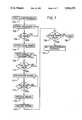
- FIG. 7is a flow diagram of descrambling operations.
- FIG. 8is a flow diagram of transmission, recording and TV screen displaying operations of point to point personal communication messages in accordance with the present invention.
- FIG. 1there is shown a representational block diagram of a transmission and receiving system that forms the environment of the present invention.
- a more detailed description of this environment, including a description of signal protocolcan be found in U.S. Pat. No. 4,713,808 issued to Gaskill et al, and copending patent application Ser. No. 07/121,139, filed Nov. 16, 1987, both of which are hereby incorporated by reference.
- a telephone 10such as a conventional dual-tone multifrequency (DTMF) keypad instrument commercially available from retail suppliers, can communicate to a clearinghouse 12 over conventional voice phone lines 14.
- Clearinghouse 12has an automatic voice response unit for communicating with a calling user.
- the main components of clearinghouse 12are a central computer 18 and processor 20, to which is attached an interface 22 that is adapted to communicate both with voice response unit 16 and with modems 24, 26, which facilitate communications, respectively, with clearinghouses, not shown, at remote locations and ultimately with broadcast radio transmission towers.
- Modem 26is adapted to communicate over data lines 28a, 28b to each transmitter and transfers digital information at the rate of 19.2 kilobaud.
- data lines 28a, 28bFour-wire private line telephone circuits are used as data lines 28a, 28b in the preferred embodiment, but high frequency radio links and microwave links can also be used.
- Input datais applied to a distribution system 30 by means of a General Data Comm (GDC) modem 32.
- GDCGeneral Data Comm
- a subcarrier generator 34is connected to modem 32 and receives a data stream from clearinghouse 12 therefrom.
- Subcarrier generator 34modulates data onto a 66.5 kHz amplitude modulation-phase shift keyed (AM-PSK) subcarrier.
- the subcarrier signalis applied to a radio station transmitter 36 where it is added to the broadcast audio signal.
- the combined signalis then FM modulated onto the station's main carrier and broadcast by means of an antenna 38.
- a modulation monitor 40is connected to FM transmitter 36 for sampling the FM signal.
- Modulation monitor 40provides the combined audio and data signals, which is called base band, to subcarrier generator 34.
- the data streamis recovered from the FM output signal and is sent to clearinghouse 12 for verification. If a difference exists between the data signal sent by clearinghouse 12 and that sampled by modulation monitor 40, the messages in error are resent by the clearinghouse 12.
- a receiver 42suitably adapted to fit into a VCR housing, not shown, is connected to an antenna 44 for receiving signals that are transmitted by FM transmitter 36 at predetermined times.
- An FM receiver 46comprises a bipolar integrated circuit capable of operating over the 88-108 MHz range, usually allocated for commercial FM broadcasting.
- FM receiver 46produces a composite signal that is a range of information from 0 to 100 kHz, which includes audio, a 19 kHz stereo pilot signal, and the subcarrier band above 53 kHz.
- FM receiver 46Connected to FM receiver 46 is a base band decoder and scanner 48 that extracts data and clock from the audio signal produced by FM receiver 46.
- the clockis derived from the 19 kHz pilot carrier, which pilot is extracted by means of a phase-locked-loop.
- a protocol decoder and error correction unit 50Connected to base band decoder and scanner 48 is a protocol decoder and error correction unit 50, which receives packets transmitted to VCR receiver 42, recognizes flags, stores appropriate information from the data stream, and detects and corrects errors contained in the stored data.
- the output of unit 50includes the actual message data transmitted to receiver 42 and time information broadcast periodically by transmitter 38.
- Unit 50also contains a packet timer, which measures time between packet receptions, in order to synchronize signal reception with signal transmission in accordance with a predefined protocol, which need not be described in greater detail herein.
- microprocessor 52Connected to unit 50 is a microprocessor 52 which controls the entire receiver, including controlling power to, and programming of, the other units 46-50.
- Microprocessor 52is responsible for interpreting data and displaying it, as required.
- Microprocessor 52enables VCR receiver 42 to store and display multiple messages. Microprocessor 52 also controls the on/off times for the receiver/decoder 46, 48 and controls standard timekeeping and display functions.
- VCR 53Connected to microprocessor 52 is a VCR 53 and a TV broadcast TV use, can also display alphanumeric information such as time and date.
- alphanumeric informationalso includes, but is not limited to, personal paging messages.
- One or more messages that have been received over a period of timecan be visually displayed and reviewed at the convenience of a paging system subscriber who prefers to view them in this manner.
- the systemcan be used to turn on VCR power and start and stop recording of broadcast material on video tape remotely. The user is therefore not required to leave the VCR powered on for unattended recording. In this manner, VCR 53 is adapted for unattended recording of broadcast material.
- the time of signal transmission and receptionis synchronized as described more fully in hereinabove cited U.S. Pat. No. 4,713,808 and patent application Ser. No. 07/121,139, filed Nov. 16, 1987. Accordingly, point to point communication device, which is part of VCR receiver 42 need not be powered for more than a small fraction of time per day, thus conserving electrical power and extending the life of the components.
- the center 242includes a standard TV receiver 202, a point to point communications receiver 203, a video tape recorder 210, a TV display monitor 213 and a system control unit 207.
- Communication and entertainment center 242receives three different types of electronic input signals via antennas 202C, 203C and coaxial cable 202D, respectively.
- Signals received via antenna 202C and coaxial cable 202Dare substantially conventional TV (video) broadcast and cable signals.
- Point to point signals received via antenna 203Care similar to RF signals received by a conventional paging receiver.
- Video and audio signals generated over line 202A by TV receiver 202are gated either to VCR 210 or to TV display monitor 213 by gate 209 or gate 216 in a conventional manner. Gating video and audio signals of TV receiver 202 to VCR 210 permits recording of such signals onto video tape, not shown, loaded in VCR 210. Gating the signals over line 202A to TV display monitor 213, however, results in the broadcast material being exhibited thereon. Gates 209 and 216 are controlled by system control unit 207, which can be a conventional microprocessor controller that is programmed according to flow diagrams hereinafter described.
- Point to point receiver 203can be a time slot paging receiver of the type shown and described in the aforementioned U.S. Pat. No. 4,713,808 or in copending U.S. patent application Ser. No. 07/121,139, filed Nov. 16, 1987.
- Point to point receiver 203receives packets of information that are directed to it specifically. Such messages are received in the form of an FM subcarrier over antenna 203C. The messages are interrogated and decoded by logical circuitry, not shown, or by a microprocessor 204 in a conventional manner. In the above referenced patent and patent application, the system microcontroller performs operations such as activating an audible signal generator or providing signals to drive an LCD display.
- microprocessor 204decodes messages received and either activates a character generator and video display generator 205 or generates control signals over line 210D. Control signals are sent to system control unit 207 or to the controls of VCR 210. Microprocessor 204 can send a series of commands to controls of VCR 210. This series of commands can correspond to messages received by point to point receiver 203 and can be any series of commands which can be entered manually via the control panel 215 of a VCR. It should be understood that manual control in this context also includes setting by remote control unit, if VCR 210 is so adapted.
- Microprocessor 204can also send a series of signals over line 204A to character generator and video display generator 205.
- the signals over line 205A from character generator and video display generator 205can be gated (a) to TV display monitor 213 where they are superimposed on the TV signals, if any, being received by TV receiver 202 or by VCR 210, or (b) to VCR 210 where they are recorded on video tape for future display.
- the TV signalsare superimposed and/or recorded in a conventional composite signal processing manner and need not be shown explicitly herein.
- Signals from TV receiver 202, from character generator and video display receiver 205 and from VCR 210are gated through gates 208, 209, 214, 215 and 216 under control of signals from system control unit 207.
- the gates and corresponding control signals therefromare conventional and are shown only symbolically in FIG. 2.
- Flow diagrams of microcomputer programs in system control unit 207 which generate appropriate control signalsare described below with reference to FIGS. 5, 6, 7 and 8.
- the systemcan operate in a number of different modes.
- the systemcan operate as a conventional TV.
- Video and audio signals received on antenna 202C or coaxial cable 202Dare simply displayed and audibly performed on TV display monitor 213.
- the broadcast channel being displayedis selected manually by means of TV control circuitry 213A.
- messages received on point to point receiver 203can be displayed alphanumerically on the TV display monitor 213 either alone or superimposed on other TV pictures.
- the messages that appear on the display shown in the above referenced patent and patent applicationappear on TV display monitor 213 rather than, or in addition to, on the display shown in the referenced patent and patent application.
- video and audio signals received on TV receiver 202can be recorded on a video tape loaded in VCR 210 either under the control of commands manually entered into VCR 210 or under the control of commands entered into VCR 210 via microprocessor 204 in response to messages received by point to point receiver 203.
- messages received by point to point receiver 203can be gated to and stored on a video tape loaded in VCR 210 for later playback.
- FIG. 3there is shown an alternate embodiment of the invention, which includes a decrypting, decoding or descrambler circuit 301 connected to TV receiver 302 by means of line 302A.
- the other components of communication and entertainment center 342are the same as shown in FIG. 2 with the exception that a line 304C connects microprocessor 304 to descrambler circuit 301.
- Descrambler circuit 301processes scrambled signals received by TV receiver via coaxial cable 302D or via antenna 302C and decodes them into standard TV signals. Such descramblers are well known and are in general use. Certain TV signals are scrambled prior to broadcast so that only authorized subscribers can receive and decode them. Normally decoding circuitry is factory set and the decoder is provided to viewers who subscribe to a particular service.
- the present inventionallows descrambler 301 to be enabled via a message having a code word and received through point to point receiver 303.
- FIG. 4there is shown a block diagram of channel descrambler 301 in greater detail.
- This descrambler 301represents one embodiment of the inventive system especially adapted for cable use.
- Descrambler 301can be disposed in the VCR housing or in the TV receiver housing, not shown.
- a signal from a television receiver 302(FIG. 3) is input over line 302A to descrambler 301.
- the cablecarries a broad band RF signal which typically includes a number of non-scrambled (non-premium) channels and a smaller number of scrambled (premium) channels which the customer pays an additional fee to receive. At least one of the channels on the cable drop is left free and carries no signal.
- This channelis referred to herein as channel "X".
- channel "X"may be television channel 17.
- the signal input from the cable dropis split by a splitter 411 into two paths, one of which is routed through a channel "X" reject filter 412 to a combiner 430.
- Reject filter 412 and combiner 430are conventional circuits formed from passive components, although active filter means can be used for reject filter 412 as will be appreciated by those skilled in the art.
- the other path from splitter 411inputs the cable drop signal into a tuner 416 which can be tuned under remote control to a desired premium channel for descrambling and viewing.
- tuner 416is input to an intermediate frequency (IF) and demodulator stage 418 for standard processing of a tuned signal.
- the tuned processed signalis then input to decoder 420 for descrambling. Any known method of descrambling the premium channels can be used in connection with the present invention.
- the descrambled signalis re-modulated at channel "X" modulator 422 to the frequency of channel "X" (e.g., channel 17).
- the descrambled premium signal then present on channel "X”is combined by combiner 430 with the rest of the broad band cable signal output from channel "X" reject filter 412.
- Combiner 430produces a composite cable signal that includes all of the original channels from the cable drop together with the descrambler premium channel on channel "X”.
- the output of combiner 430is applied over line 301A ultimately to video tape recorder 310 or TV display monitor 313 (FIG. 3).
- Channel "X" reject filter 412is designed to prevent the output of channel “X” modulator 422 from leaking back onto the cable system. It also serves to clean off any residual noise on the cable drop at channel "X", thereby providing a clean channel for insertion of the premium program re-modulated by channel "X" modulator 422.
- the tuner and descrambler section of the channel descrambler 301(i.e., tuner 416, IF and demodulator stage 418, decoder 420) is controlled by control circuitry 424 to step through the channels tunable by tuner 416 one at a time.
- a cable system customermay be authorized for one premium channel or more than one.
- the authorizationcan be bestowed, withdrawn or changed by a cable system operator by means of an appropriately encoded signal transmission received by point to point receiver 303, compared by microprocessor 304 and entered in control unit 424.
- Program controlwill increment the channel tuned by tuner 416 until the desired premium channel is selected.
- An indication of the premium channel tunedcan be displayed on the user's television screen 313. Once the system has selected a premium channel for viewing, the video tape recorder 310 is tuned to channel "X" (e.g., channel 17).
- the user interface with channel descrambler 301can be controlled by programming control section 424 by means of microprocessor 304 to respond to signals received on the user's unique receiving frequency. For example, if channel 17 is used for channel "X", control section 424 would be programmed to "learn” the signal received on the user's receiving frequency when channel 17 is selected. This would be accomplished by placing the control circuitry 424 into a learn mode and transmitting channel 17 on the user's frequency. Control section 424 will then recognize the channel 17 signal from transmitter 38 (FIG. 1) as the "switch” which increments tuner 416 to the next channel. Data indicative of the channel 17 signal emitted from transmitter 38 is stored in memory within control section 424 so the signal can be detected each time it occurs. The user can then step through the premium channels tunable by tuner 41 by repeatedly transmitting channel 17.
- a code wordis required to enable a user to descramble a specified broadcast channel.
- the code wordmust be received by point to point receiver 303 (FIG. 3), transmitted to microprocessor 304 and thence to control unit 424 of descrambler 301.
- FIGS. 5-8are representative of computer programs or microprograms that may be executed by microprocessor 204 (FIG. 2) in cooperation with system control logic 207 or other logic, not shown.
- a timing information signalis continuously broadcast from clearinghouse 12 (FIG. 1) through FM radio transmitter 38, step 500.
- Point to point receiver 46is automatically activated periodically at predetermined times in accordance with predefined protocol.
- the signalis received, step 504.
- step 508the timing signal sets the clock with the accurate time, step 510.
- step 508the timing signal resets the clock, step 512. In this way, the VCR clock is set or updated with a new timing signal automatically and periodically at each time slot during which point to point receiver 46 is activated.
- a flow chart of system programming from a remote locationis shown.
- a usercalls clearinghouse 12 (FIG. 1) by using telephone 10, step 600.
- a synthesized voiceinterrogates the user in accordance with a menu script, so that the user is directed to enter certain keys from a telephone keypad at certain times.
- step 602the user enters the identification number of the point to point receiver 46 that is to receive the programming information.
- Clearinghouse 12determines whether the identification number is valid, step 604, and requests another number if the first one does not identify a valid point to point receiver 46.
- step 606the user enters program information, such as channel to be recorded, starting date and time, and ending time.
- An appropriately encoded signalis sent from clearinghouse 12 to transmission distribution system 30, step 608, and thence to FM radio transmitter 38.
- clearinghouse 12determines when a reserved time slot has been reached. If the time slot has not been reached, step 610, broadcast of the appropriate programming signal is delayed. When the time slot has been reached, the programming signal is broadcast, step 612, by radio transmitter 38. If point to point receiver 46 is not activated, step 614, the signal is retransmitted. When receiver 46 is activated, step 614, it receives the signal, step 616, and VCR control and microprocessor 52 decode the signal, step 618.
- VCR 53The information extracted from the signal is sent to VCR 53, step 620, for programming.
- VCR 53Once VCR 53 is suitably programmed, a period of time elapses during which VCR 53 is in a wait state, step 622.
- VCR 53begins the recording operation, step 624.
- a usercalls clearinghouse 12 (FIG. 1) by using telephone 10, step 700.
- a synthesized voiceinterrogates the user in accordance with a menu script, so that the user is directed to enter certain keys from a telephone keypad at certain times.
- step 702the user enters the identification number of the point to point receiver 4 that is to receive the programming information.
- Clearinghouse 12determines whether the identification number is valid, step 704, and requests another number if the first one does not identify a valid point to point receiver 46.
- step 706the user enters descrambling information, including the channel to be descrambled and a unique code word authorized for such purposes.
- An appropriately encoded signalis sent from clearinghouse 12 to transmission distribution system 30, step 708, and thence to FM radio transmitter 38.
- clearinghouse 12determines when a reserved time slot has been reached. If the time slot has not been reached, step 710, broadcast of the appropriate programming signal is delayed. When the time slot has been reached, the programming signal is broadcast, step 712, by radio transmitter 38. If point to point receiver 46 is not activated, step 714, the signal is retransmitted. When receiver 46 is activated, step 714, it receives the signal, step 716, and VCR control and microprocessor 52 decode the signal, step 718, extracting the descrambling information as well as the code word.
- step 720The information extracted from the signal is compared by microprocessor 52 to determine whether it is valid for the operation requested, step 720. If the code word is not valid, no further action is taken, step 722. If the code word is found to be valid, however, step 720, a signal is sent from microprocessor 304 (FIG. 4) to control unit 424 of descrambler 301 so as to allow the specified channel to be descrambled.
- microprocessor 304FIG. 424 of descrambler 301
- a flow chartis shown describing the storing and displaying of personal message from remote locations.
- a usercalls clearinghouse 12 (FIG. 1) by using telephone 10, step 800.
- a synthesized voiceinterrogates the user in accordance with a menu script, so that the user is directed to enter certain keys from a telephone keypad at certain times.
- step 802the user enters the identification number of the point to point receiver 46 that is to receive the programming information.
- Clearinghouse 12determines whether the identification number is valid, step 804, and requests another number if the first one does not identify a valid point to point receiver 46.
- step 806the user enters a message, such as a personal paging message intended for a specified individual.
- An appropriately encoded signalis sent from clearinghouse 12 to transmission distribution system 30, step 808, and thence to FM radio transmitter 38.
- clearinghouse 12determines when a reserved time slot has been reached. If the time slot has not been reached, step 810, broadcast of the appropriate programming signal is delayed. When the time slot has been reached, the programming signal is broadcast, step 812, by radio transmitter 38. If point to point receiver 46 is not activated, step 814, the signal is retransmitted. When receiver 46 is activated, step 814, it receives the signal, step 816, and VCR control and microprocessor 52 decode the signal, step 818, extracting the personal message.
- microprocessor 204sends an appropriate signal to system control 207, which determines whether TV display monitor 213 is operating, step 820. At the same time, microprocessor 204 sends the message signal to character generator and video display generator 205 for suitable visual formatting of the message. If monitor 213 is not ON, the control signal from system control 207 is routed through gate 208 and the personal message from character generator and video display generator 205 is recorded on video tape, not shown, loaded in VCR 210, step 822. The system then waits for the next personal message to arrive by means of point to point receiver 46, step 824.
- step 820the control signal from system control 207 is routed through gate 216 and the personal message from character generator and video display generator 205 is superimposed by means of a composite video signal onto the existing image displayed on TV display monitor 213, step 826.
- step 828When the VCR user accesses the entertainment and communication center 242, step 828, he may turn his TV display monitor 213 ON. If monitor 213 is turned ON, step 830, and one or more messages have been recorded on video tape, the control signal from system control 207 is routed over line 210C to direct VCR 210 to send the recorded message(s) by means of gate 214 to control circuitry 213A of TV display monitor 213.
- the personal message(s) from character generator and video display generator 205is superimposed by means of a composite video signal onto the existing image displayed on TV display monitor 213, step 826.
- control signal from system control 207is routed over line 207A to gate 216 to control circuitry 213A of TV display monitor 213.
- the personal message from character generator and video display generator 205is superimposed by means of a composite video signal onto the existing image displayed on TV display monitor 213, step 826.
- control signal from system control 207is again routed over line 210C to direct VCR 210 to send the recorded message(s) by means of gate 214 to control circuitry 213A of TV display monitor 213.
- the personal message(s) from character generator and video display generator 205is simply displayed on TV display monitor 213, step 832.
- one or more messagescan be sent by means of a telephone 10 to instruct VCR point to point receiver 46 to record the personal messages onto video tape for later playback and review.
Landscapes
- Engineering & Computer Science (AREA)
- Multimedia (AREA)
- Signal Processing (AREA)
- Television Signal Processing For Recording (AREA)
- Indexing, Searching, Synchronizing, And The Amount Of Synchronization Travel Of Record Carriers (AREA)
- Circuits Of Receivers In General (AREA)
- Audible And Visible Signals (AREA)
- Two-Way Televisions, Distribution Of Moving Picture Or The Like (AREA)
Abstract
Description
Claims (13)
Priority Applications (5)
| Application Number | Priority Date | Filing Date | Title |
|---|---|---|---|
| US07/295,172US5016273A (en) | 1989-01-09 | 1989-01-09 | Dual communication mode video tape recorder |
| JP90502827AJPH04504189A (en) | 1989-01-09 | 1990-01-05 | Duplex mode video tape recorder |
| AU49669/90AAU4966990A (en) | 1989-01-09 | 1990-01-05 | Dual communication mode video tape recorder |
| PCT/US1990/000145WO1990008442A1 (en) | 1989-01-09 | 1990-01-05 | Dual communication mode video tape recorder |
| US08/170,644US5467197A (en) | 1989-01-09 | 1993-12-16 | Dual communication mode video tape recorder |
Applications Claiming Priority (1)
| Application Number | Priority Date | Filing Date | Title |
|---|---|---|---|
| US07/295,172US5016273A (en) | 1989-01-09 | 1989-01-09 | Dual communication mode video tape recorder |
Related Child Applications (1)
| Application Number | Title | Priority Date | Filing Date |
|---|---|---|---|
| US58305390AContinuation | 1989-01-09 | 1990-09-14 |
Publications (1)
| Publication Number | Publication Date |
|---|---|
| US5016273Atrue US5016273A (en) | 1991-05-14 |
Family
ID=23136543
Family Applications (2)
| Application Number | Title | Priority Date | Filing Date |
|---|---|---|---|
| US07/295,172Expired - LifetimeUS5016273A (en) | 1989-01-09 | 1989-01-09 | Dual communication mode video tape recorder |
| US08/170,644Expired - LifetimeUS5467197A (en) | 1989-01-09 | 1993-12-16 | Dual communication mode video tape recorder |
Family Applications After (1)
| Application Number | Title | Priority Date | Filing Date |
|---|---|---|---|
| US08/170,644Expired - LifetimeUS5467197A (en) | 1989-01-09 | 1993-12-16 | Dual communication mode video tape recorder |
Country Status (4)
| Country | Link |
|---|---|
| US (2) | US5016273A (en) |
| JP (1) | JPH04504189A (en) |
| AU (1) | AU4966990A (en) |
| WO (1) | WO1990008442A1 (en) |
Cited By (79)
| Publication number | Priority date | Publication date | Assignee | Title |
|---|---|---|---|---|
| US5195134A (en)* | 1990-03-27 | 1993-03-16 | Sony Corporation | Transmitting, receiving, and automatic recording system for programs with time and channel information |
| US5260916A (en)* | 1989-03-22 | 1993-11-09 | Diehl Gmbh & Co. | Timer |
| US5260778A (en)* | 1990-06-26 | 1993-11-09 | General Instrument Corporation | Apparatus for selective distribution of messages over a communications network |
| WO1994021081A3 (en)* | 1993-03-05 | 1994-11-10 | Roy J Mankovitz | Apparatus and method using compressed codes for television program record scheduling |
| US5414756A (en)* | 1992-06-26 | 1995-05-09 | Smart Vcr Limited Partnership | Telephonically programmable apparatus |
| US5432558A (en)* | 1992-10-31 | 1995-07-11 | Samsung Electronics Co., Ltd. | Circuit and method for transmitting/receiving a code-inserted video signal |
| US5467197A (en)* | 1989-01-09 | 1995-11-14 | Seiko Corporation | Dual communication mode video tape recorder |
| US5475375A (en)* | 1985-10-16 | 1995-12-12 | Supra Products, Inc. | Electronic access control systems |
| US5489894A (en)* | 1991-07-08 | 1996-02-06 | Motorola, Inc. | Television paging system |
| US5537473A (en)* | 1991-07-08 | 1996-07-16 | Amstrad Public Limited Company | Video recorder system |
| US5550535A (en)* | 1992-08-14 | 1996-08-27 | Seiko Communications Holding N.V. | Bank balance notification by wristwatch pager |
| US5553123A (en)* | 1994-06-09 | 1996-09-03 | Gemstar Development Corporation | Method for downloading setup data via telephone to an appliance controller |
| US5602536A (en)* | 1985-10-16 | 1997-02-11 | Supra Products, Inc. | Data synchronization method for use with portable, microprocessor-based device |
| US5625464A (en)* | 1990-03-16 | 1997-04-29 | Thomson Consumer Electronics | Continuous television transmission reproduction and playback |
| US5654696A (en)* | 1985-10-16 | 1997-08-05 | Supra Products, Inc. | Method for transferring auxillary data using components of a secure entry system |
| US5677895A (en)* | 1994-08-18 | 1997-10-14 | Mankovitz; Roy J. | Apparatus and methods for setting timepieces |
| US5877699A (en)* | 1992-06-05 | 1999-03-02 | U.S. Philips Corporation | Displaying data transmitted by radio |
| US5887243A (en) | 1981-11-03 | 1999-03-23 | Personalized Media Communications, L.L.C. | Signal processing apparatus and methods |
| US5991374A (en)* | 1996-08-08 | 1999-11-23 | Hazenfield; Joey C. | Programmable messaging system for controlling playback of messages on remote music on-hold- compatible telephone systems and other message output devices |
| US5991498A (en)* | 1991-05-24 | 1999-11-23 | Starsight Telecast, Inc. | VCR programming system |
| US6052145A (en)* | 1995-01-05 | 2000-04-18 | Gemstar Development Corporation | System and method for controlling the broadcast and recording of television programs and for distributing information to be displayed on a television screen |
| US6058238A (en)* | 1994-10-27 | 2000-05-02 | Index Systems, Inc. | Identifier generation and remote programming for individually addressable video cassette recorders |
| US6072402A (en)* | 1992-01-09 | 2000-06-06 | Slc Technologies, Inc. | Secure entry system with radio communications |
| US6195530B1 (en) | 1988-12-23 | 2001-02-27 | Scientific-Atlanta, Inc. | Selective messaging via on-screen display |
| US6204796B1 (en) | 1994-07-01 | 2001-03-20 | Gemstar Development Corporation | Apparatus and methods for generating codes for controlling appliances from a remote controller |
| US6233734B1 (en) | 1995-01-05 | 2001-05-15 | Videoguide, Inc. | System and method for controlling the broadcast and recording of television programs and for distributing information to be displayed on a television screen |
| WO2001061997A1 (en)* | 2000-02-18 | 2001-08-23 | Alexander Franco | Use of web pages to remotely program a broadcast content recording system |
| EP0886967A4 (en)* | 1996-02-23 | 2002-01-23 | Guide E Inc | Two-way interactive television system |
| US20020029384A1 (en)* | 2000-07-20 | 2002-03-07 | Griggs Theodore L. | Mechanism for distributing content data |
| US20020046407A1 (en)* | 2000-02-18 | 2002-04-18 | Alexander Franco | Use of web pages to remotely program a broadcast content recording system |
| US20020053081A1 (en)* | 2000-10-31 | 2002-05-02 | Digitaldeck, Inc. | Adaptable programming guide for networked devices |
| KR100374381B1 (en)* | 1995-11-23 | 2003-05-09 | 엘지전자 주식회사 | Video display device with wireless call reception function and control method |
| US6587634B2 (en)* | 2001-02-15 | 2003-07-01 | Avica Technology Corporation | Paging during media loading |
| US6618680B2 (en)* | 2001-05-09 | 2003-09-09 | The United States Of America As Represented By The Secretary Of The Interior | Signal processor apparatus for rotating water current meter |
| US20040001720A1 (en)* | 2002-06-27 | 2004-01-01 | Krill Jerry A. | Satellite-based mobile communication system |
| US20040021770A1 (en)* | 2002-07-01 | 2004-02-05 | Krill Jerry A. | System and method for real-time image control and processing for use in wide area space based surveillance |
| US20040210935A1 (en)* | 1995-10-02 | 2004-10-21 | Starsight Telecast, Inc. | Interactive computer system for providing television schedule information |
| US20040255327A1 (en)* | 2003-06-12 | 2004-12-16 | Digital Deck, Inc. | Media content distribution system and method |
| US6859614B1 (en)* | 1996-06-24 | 2005-02-22 | Samsung Electronics Co., Ltd. | Apparatus and method for controlling priority order of access to memory |
| US20050278768A1 (en)* | 1996-12-10 | 2005-12-15 | United Video Properties, Inc. | Internet television program guide system |
| US20070052549A1 (en)* | 2005-08-22 | 2007-03-08 | Contec Corporation | Apparatus and method for updating encoded signal information stored in a remote control unit through direct key entry |
| US20080134239A1 (en)* | 1998-07-29 | 2008-06-05 | Starsight Telecast Inc. | Multiple interactive electronic program guide system and methods |
| US20080189737A1 (en)* | 1998-07-17 | 2008-08-07 | Ellis Michael D | Interactive television program guide system having multiple devices within a household |
| US20100192177A1 (en)* | 2000-03-31 | 2010-07-29 | United Video Properties, Inc. | Interactive media system and method for presenting pause-time content |
| US7769344B1 (en) | 1981-11-03 | 2010-08-03 | Personalized Media Communications, Llc | Signal processing apparatus and methods |
| US7913278B2 (en) | 1998-07-17 | 2011-03-22 | United Video Properties, Inc. | Interactive television program guide with remote access |
| US20110113448A1 (en)* | 2000-07-20 | 2011-05-12 | Resource Consortium Limited | Adaptable Programming Guide for Networked Devices |
| US8087047B2 (en) | 2007-04-20 | 2011-12-27 | United Video Properties, Inc. | Systems and methods for providing remote access to interactive media guidance applications |
| US8327403B1 (en) | 2007-09-07 | 2012-12-04 | United Video Properties, Inc. | Systems and methods for providing remote program ordering on a user device via a web server |
| US8453174B2 (en) | 1995-10-02 | 2013-05-28 | Starsight Telecast, Inc. | Method and system for displaying advertising, video, and program schedule listing |
| US8528032B2 (en) | 1998-07-14 | 2013-09-03 | United Video Properties, Inc. | Client-server based interactive television program guide system with remote server recording |
| US20130243395A1 (en)* | 2012-03-15 | 2013-09-19 | Echostar Technologies, Llc | Managing remote distribution of content recorded at a television receiver |
| US8601526B2 (en) | 2008-06-13 | 2013-12-03 | United Video Properties, Inc. | Systems and methods for displaying media content and media guidance information |
| US8762492B2 (en) | 1997-09-18 | 2014-06-24 | United Video Properties, Inc. | Electronic mail reminder for an internet television program guide |
| US8776125B2 (en) | 1996-05-03 | 2014-07-08 | Starsight Telecast Inc. | Method and system for displaying advertisements in an electronic program guide |
| US8806533B1 (en) | 2004-10-08 | 2014-08-12 | United Video Properties, Inc. | System and method for using television information codes |
| US8832742B2 (en) | 2006-10-06 | 2014-09-09 | United Video Properties, Inc. | Systems and methods for acquiring, categorizing and delivering media in interactive media guidance applications |
| US8850476B2 (en) | 2011-08-23 | 2014-09-30 | Echostar Technologies L.L.C. | Backwards guide |
| US8892495B2 (en) | 1991-12-23 | 2014-11-18 | Blanding Hovenweep, Llc | Adaptive pattern recognition based controller apparatus and method and human-interface therefore |
| US8904441B2 (en) | 2003-11-06 | 2014-12-02 | United Video Properties, Inc. | Systems and methods for providing program suggestions in an interactive television program guide |
| US20150156553A1 (en)* | 1996-09-03 | 2015-06-04 | Rovi Guides, Inc. | Schedule system with enhanced recording capability |
| US9071872B2 (en) | 2003-01-30 | 2015-06-30 | Rovi Guides, Inc. | Interactive television systems with digital video recording and adjustable reminders |
| US9113207B2 (en) | 1995-10-02 | 2015-08-18 | Rovi Guides, Inc. | Systems and methods for contextually linking television program information |
| US9118958B2 (en) | 1999-12-10 | 2015-08-25 | Rovi Guides, Inc. | Systems and methods for coordinating interactive and passive advertisement and merchandising opportunities |
| US9125169B2 (en) | 2011-12-23 | 2015-09-01 | Rovi Guides, Inc. | Methods and systems for performing actions based on location-based rules |
| US9166714B2 (en) | 2009-09-11 | 2015-10-20 | Veveo, Inc. | Method of and system for presenting enriched video viewing analytics |
| US9191722B2 (en) | 1997-07-21 | 2015-11-17 | Rovi Guides, Inc. | System and method for modifying advertisement responsive to EPG information |
| US9197943B2 (en) | 1998-12-03 | 2015-11-24 | Rovi Guides, Inc. | Electronic program guide with related-program search feature |
| US9204193B2 (en) | 2010-05-14 | 2015-12-01 | Rovi Guides, Inc. | Systems and methods for media detection and filtering using a parental control logging application |
| US9253262B2 (en) | 2013-01-24 | 2016-02-02 | Rovi Guides, Inc. | Systems and methods for connecting media devices through web sockets |
| US9288521B2 (en) | 2014-05-28 | 2016-03-15 | Rovi Guides, Inc. | Systems and methods for updating media asset data based on pause point in the media asset |
| US9294799B2 (en) | 2000-10-11 | 2016-03-22 | Rovi Guides, Inc. | Systems and methods for providing storage of data on servers in an on-demand media delivery system |
| US9307281B2 (en) | 2007-03-22 | 2016-04-05 | Rovi Guides, Inc. | User defined rules for assigning destinations of content |
| US9319735B2 (en) | 1995-06-07 | 2016-04-19 | Rovi Guides, Inc. | Electronic television program guide schedule system and method with data feed access |
| US9326025B2 (en) | 2007-03-09 | 2016-04-26 | Rovi Technologies Corporation | Media content search results ranked by popularity |
| US9426509B2 (en) | 1998-08-21 | 2016-08-23 | Rovi Guides, Inc. | Client-server electronic program guide |
| US9535563B2 (en) | 1999-02-01 | 2017-01-03 | Blanding Hovenweep, Llc | Internet appliance system and method |
| US10063934B2 (en) | 2008-11-25 | 2018-08-28 | Rovi Technologies Corporation | Reducing unicast session duration with restart TV |
| USRE47642E1 (en) | 1981-11-03 | 2019-10-08 | Personalized Media Communications LLC | Signal processing apparatus and methods |
Families Citing this family (31)
| Publication number | Priority date | Publication date | Assignee | Title |
|---|---|---|---|---|
| GB2257557B (en)* | 1991-07-08 | 1994-11-16 | Amstrad Plc | Video recorder system |
| JPH06284216A (en)* | 1993-03-25 | 1994-10-07 | Sony Corp | Check and adjustment system for electronic device using telephone line |
| EP2385527A3 (en)* | 1993-06-07 | 2012-12-19 | Samsung Electronics Co., Ltd. | Digital information recording-reproducing apparatus |
| US6081693A (en)* | 1997-02-07 | 2000-06-27 | Sony Corporation | Television and radio information pager |
| US7062150B1 (en)* | 1998-01-05 | 2006-06-13 | Gateway Inc. | System and method for reminding users of upcoming scheduled recordings |
| US7502430B2 (en) | 2001-04-27 | 2009-03-10 | The Directv Group, Inc. | Coherent averaging for measuring traveling wave tube amplifier nonlinearity |
| US7151807B2 (en) | 2001-04-27 | 2006-12-19 | The Directv Group, Inc. | Fast acquisition of timing and carrier frequency from received signal |
| US7639759B2 (en) | 2001-04-27 | 2009-12-29 | The Directv Group, Inc. | Carrier to noise ratio estimations from a received signal |
| US7423987B2 (en) | 2001-04-27 | 2008-09-09 | The Directv Group, Inc. | Feeder link configurations to support layered modulation for digital signals |
| US7173981B1 (en) | 2001-04-27 | 2007-02-06 | The Directv Group, Inc. | Dual layer signal processing in a layered modulation digital signal system |
| US7245671B1 (en) | 2001-04-27 | 2007-07-17 | The Directv Group, Inc. | Preprocessing signal layers in a layered modulation digital signal system to use legacy receivers |
| US7184489B2 (en) | 2001-04-27 | 2007-02-27 | The Directv Group, Inc. | Optimization technique for layered modulation |
| US7471735B2 (en)* | 2001-04-27 | 2008-12-30 | The Directv Group, Inc. | Maximizing power and spectral efficiencies for layered and conventional modulations |
| US7209524B2 (en)* | 2001-04-27 | 2007-04-24 | The Directv Group, Inc. | Layered modulation for digital signals |
| US7184473B2 (en) | 2001-04-27 | 2007-02-27 | The Directv Group, Inc. | Equalizers for layered modulated and other signals |
| US7483505B2 (en) | 2001-04-27 | 2009-01-27 | The Directv Group, Inc. | Unblind equalizer architecture for digital communication systems |
| US7822154B2 (en) | 2001-04-27 | 2010-10-26 | The Directv Group, Inc. | Signal, interference and noise power measurement |
| US7583728B2 (en) | 2002-10-25 | 2009-09-01 | The Directv Group, Inc. | Equalizers for layered modulated and other signals |
| US8005035B2 (en) | 2001-04-27 | 2011-08-23 | The Directv Group, Inc. | Online output multiplexer filter measurement |
| AU2003280499A1 (en) | 2002-07-01 | 2004-01-19 | The Directv Group, Inc. | Improving hierarchical 8psk performance |
| ES2604453T3 (en) | 2002-07-03 | 2017-03-07 | The Directv Group, Inc. | Method and apparatus for layered modulation |
| ES2398213T3 (en) | 2002-10-25 | 2013-03-14 | The Directv Group, Inc. | Low complexity layer modulation signal processor |
| ATE461553T1 (en) | 2002-10-25 | 2010-04-15 | Directv Group Inc | ESTIMATING THE WORKING POINT OF A NONLINEAR PROPAGATED WAVE STIR AMPLIFIER |
| US7463676B2 (en) | 2002-10-25 | 2008-12-09 | The Directv Group, Inc. | On-line phase noise measurement for layered modulation |
| ATE491296T1 (en) | 2002-10-25 | 2010-12-15 | Directv Group Inc | METHOD AND APPARATUS FOR ADJUSTING CARRIER POWER REQUIREMENTS ACCORDING TO AVAILABILITY IN LAYERED MODULATION SYSTEMS |
| US7529312B2 (en) | 2002-10-25 | 2009-05-05 | The Directv Group, Inc. | Layered modulation for terrestrial ATSC applications |
| ES2321184T3 (en)* | 2002-10-25 | 2009-06-03 | The Directv Group, Inc. | CONCORDANCE OF AMPLITUDE AND PHASE FOR RECEPTION OF MODULATION IN LAYERS. |
| US7474710B2 (en) | 2002-10-25 | 2009-01-06 | The Directv Group, Inc. | Amplitude and phase matching for layered modulation reception |
| EP1511306A1 (en)* | 2003-09-01 | 2005-03-02 | Thomson Licensing S.A. | Method for detecting source status changes during time-shift recording |
| US7502429B2 (en) | 2003-10-10 | 2009-03-10 | The Directv Group, Inc. | Equalization for traveling wave tube amplifier nonlinearity measurements |
| US9025939B2 (en) | 2012-03-15 | 2015-05-05 | Echostar Technologies L.L.C. | Timer distribution across multiple client devices |
Citations (5)
| Publication number | Priority date | Publication date | Assignee | Title |
|---|---|---|---|---|
| US4337480A (en)* | 1979-02-15 | 1982-06-29 | Syndicat Des Constructeurs D'appareils Radio Recepteurs Et Televiseurs (Scart) | Dynamic audio-video interconnection system |
| US4418364A (en)* | 1981-09-28 | 1983-11-29 | Rca Corporation | Video player apparatus having caption generator |
| US4525820A (en)* | 1980-03-19 | 1985-06-25 | Hitachi, Ltd. | Function selecting method and system for an audio/video recording and reproducing system |
| US4746919A (en)* | 1986-03-28 | 1988-05-24 | Rca Licensing Corporation | Remote control system with key function display provisions |
| US4879611A (en)* | 1986-08-01 | 1989-11-07 | Sanyo Electric Co., Ltd. | Record mode setting apparatus responsive to transmitted code containing time-start information |
Family Cites Families (10)
| Publication number | Priority date | Publication date | Assignee | Title |
|---|---|---|---|---|
| US4605973A (en)* | 1982-08-23 | 1986-08-12 | Kohorn H Von | System, apparatus and method for recording and editing broadcast transmissions |
| US4625080A (en)* | 1983-05-03 | 1986-11-25 | Scott Michael M | Remote video recorder programming apparatus operating over telephone lines |
| US4787063A (en)* | 1984-10-19 | 1988-11-22 | Francis Muguet | Acquisition and transmission system for a recorder and a computer center |
| US4706121B1 (en)* | 1985-07-12 | 1993-12-14 | Insight Telecast, Inc. | Tv schedule system and process |
| DE3819863A1 (en)* | 1987-06-12 | 1989-01-05 | Matsushita Electric Industrial Co Ltd | REMOTE CONTROL DEVICE FOR ELECTRONIC DEVICES |
| DE3856057T2 (en)* | 1987-07-20 | 1998-10-29 | Philips Electronics Nv | Television transmission system |
| US4841562A (en)* | 1987-07-24 | 1989-06-20 | Steven Lem | Telephone VCR control |
| US4907079A (en)* | 1987-09-28 | 1990-03-06 | Teleview Rating Corporation, Inc. | System for monitoring and control of home entertainment electronic devices |
| US4977455B1 (en)* | 1988-07-15 | 1993-04-13 | System and process for vcr scheduling | |
| US5016273A (en)* | 1989-01-09 | 1991-05-14 | At&E Corporation | Dual communication mode video tape recorder |
- 1989
- 1989-01-09USUS07/295,172patent/US5016273A/ennot_activeExpired - Lifetime
- 1990
- 1990-01-05AUAU49669/90Apatent/AU4966990A/ennot_activeAbandoned
- 1990-01-05WOPCT/US1990/000145patent/WO1990008442A1/enunknown
- 1990-01-05JPJP90502827Apatent/JPH04504189A/enactivePending
- 1993
- 1993-12-16USUS08/170,644patent/US5467197A/ennot_activeExpired - Lifetime
Patent Citations (5)
| Publication number | Priority date | Publication date | Assignee | Title |
|---|---|---|---|---|
| US4337480A (en)* | 1979-02-15 | 1982-06-29 | Syndicat Des Constructeurs D'appareils Radio Recepteurs Et Televiseurs (Scart) | Dynamic audio-video interconnection system |
| US4525820A (en)* | 1980-03-19 | 1985-06-25 | Hitachi, Ltd. | Function selecting method and system for an audio/video recording and reproducing system |
| US4418364A (en)* | 1981-09-28 | 1983-11-29 | Rca Corporation | Video player apparatus having caption generator |
| US4746919A (en)* | 1986-03-28 | 1988-05-24 | Rca Licensing Corporation | Remote control system with key function display provisions |
| US4879611A (en)* | 1986-08-01 | 1989-11-07 | Sanyo Electric Co., Ltd. | Record mode setting apparatus responsive to transmitted code containing time-start information |
Cited By (236)
| Publication number | Priority date | Publication date | Assignee | Title |
|---|---|---|---|---|
| US9043859B1 (en) | 1981-11-02 | 2015-05-26 | Personalized Media Communications, Llc | Signal processing apparatus and methods |
| US8191091B1 (en) | 1981-11-03 | 2012-05-29 | Personalized Media Communications, Llc | Signal processing apparatus and methods |
| US7865920B1 (en) | 1981-11-03 | 2011-01-04 | Personalized Media Communications LLC | Signal processing apparatus and methods |
| USRE48682E1 (en) | 1981-11-03 | 2021-08-10 | Personalized Media Communications LLC | Providing subscriber specific content in a network |
| USRE48633E1 (en) | 1981-11-03 | 2021-07-06 | Personalized Media Communications LLC | Reprogramming of a programmable device of a specific version |
| USRE48565E1 (en) | 1981-11-03 | 2021-05-18 | Personalized Media Communications LLC | Providing a subscriber specific solution in a computer network |
| USRE48484E1 (en) | 1981-11-03 | 2021-03-23 | Personalized Media Communications, Llc | Signal processing apparatus and methods |
| US10715835B1 (en) | 1981-11-03 | 2020-07-14 | John Christopher Harvey | Signal processing apparatus and methods |
| US10616638B1 (en) | 1981-11-03 | 2020-04-07 | Personalized Media Communications LLC | Signal processing apparatus and methods |
| US10609425B1 (en) | 1981-11-03 | 2020-03-31 | Personalized Media Communications, L.L.C. | Signal processing apparatus and methods |
| USRE47867E1 (en) | 1981-11-03 | 2020-02-18 | Personalized Media Communications LLC | Signal processing apparatus and methods |
| US10523350B1 (en) | 1981-11-03 | 2019-12-31 | Personalized Media Communications LLC | Signal processing apparatus and methods |
| USRE47642E1 (en) | 1981-11-03 | 2019-10-08 | Personalized Media Communications LLC | Signal processing apparatus and methods |
| US10334292B1 (en) | 1981-11-03 | 2019-06-25 | Personalized Media Communications LLC | Signal processing apparatus and methods |
| US9674560B1 (en) | 1981-11-03 | 2017-06-06 | Personalized Media Communications LLC | Signal processing apparatus and methods |
| US9294205B1 (en) | 1981-11-03 | 2016-03-22 | Personalized Media Communications LLC | Signal processing apparatus and methods |
| US9210370B1 (en) | 1981-11-03 | 2015-12-08 | Personalized Media Communications LLC | Signal processing apparatus and methods |
| US9038124B1 (en) | 1981-11-03 | 2015-05-19 | Personalized Media Communications, Llc | Signal processing apparatus and methods |
| US8973034B1 (en) | 1981-11-03 | 2015-03-03 | Personalized Media Communications LLC | Signal processing apparatus and methods |
| US8914825B1 (en) | 1981-11-03 | 2014-12-16 | Personalized Media Communications LLC | Signal processing apparatus and methods |
| US5887243A (en) | 1981-11-03 | 1999-03-23 | Personalized Media Communications, L.L.C. | Signal processing apparatus and methods |
| US8893177B1 (en) | 1981-11-03 | 2014-11-18 | {Personalized Media Communications, LLC | Signal processing apparatus and methods |
| US8869228B1 (en) | 1981-11-03 | 2014-10-21 | Personalized Media Communications, Llc | Signal processing apparatus and methods |
| US8869229B1 (en) | 1981-11-03 | 2014-10-21 | Personalized Media Communications, Llc | Signal processing apparatus and methods |
| US8839293B1 (en) | 1981-11-03 | 2014-09-16 | Personalized Media Communications, Llc | Signal processing apparatus and methods |
| US8804727B1 (en) | 1981-11-03 | 2014-08-12 | Personalized Media Communications, Llc | Signal processing apparatus and methods |
| US8752088B1 (en) | 1981-11-03 | 2014-06-10 | Personalized Media Communications LLC | Signal processing apparatus and methods |
| US8739241B1 (en) | 1981-11-03 | 2014-05-27 | Personalized Media Communications LLC | Signal processing apparatus and methods |
| US8713624B1 (en) | 1981-11-03 | 2014-04-29 | Personalized Media Communications LLC | Signal processing apparatus and methods |
| US8711885B1 (en) | 1981-11-03 | 2014-04-29 | Personalized Media Communications LLC | Signal processing apparatus and methods |
| US8683539B1 (en) | 1981-11-03 | 2014-03-25 | Personalized Media Communications, Llc | Signal processing apparatus and methods |
| US8675775B1 (en) | 1981-11-03 | 2014-03-18 | Personalized Media Communications, Llc | Signal processing apparatus and methods |
| US8646001B1 (en) | 1981-11-03 | 2014-02-04 | Personalized Media Communications, Llc | Signal processing apparatus and methods |
| US8640184B1 (en) | 1981-11-03 | 2014-01-28 | Personalized Media Communications, Llc | Signal processing apparatus and methods |
| US8635644B1 (en) | 1981-11-03 | 2014-01-21 | Personalized Media Communications LLC | Signal processing apparatus and methods |
| US8621547B1 (en) | 1981-11-03 | 2013-12-31 | Personalized Media Communications, Llc | Signal processing apparatus and methods |
| US8613034B1 (en) | 1981-11-03 | 2013-12-17 | Personalized Media Communications, Llc | Signal processing apparatus and methods |
| US8607296B1 (en) | 1981-11-03 | 2013-12-10 | Personalized Media Communications LLC | Signal processing apparatus and methods |
| US8601528B1 (en) | 1981-11-03 | 2013-12-03 | Personalized Media Communications, L.L.C. | Signal processing apparatus and methods |
| US8587720B1 (en) | 1981-11-03 | 2013-11-19 | Personalized Media Communications LLC | Signal processing apparatus and methods |
| US8584162B1 (en) | 1981-11-03 | 2013-11-12 | Personalized Media Communications LLC | Signal processing apparatus and methods |
| US8572671B1 (en) | 1981-11-03 | 2013-10-29 | Personalized Media Communications LLC | Signal processing apparatus and methods |
| US8566868B1 (en) | 1981-11-03 | 2013-10-22 | Personalized Media Communications, L.L.C. | Signal processing apparatus and methods |
| US8559635B1 (en) | 1981-11-03 | 2013-10-15 | Personalized Media Communications, L.L.C. | Signal processing apparatus and methods |
| US8558950B1 (en) | 1981-11-03 | 2013-10-15 | Personalized Media Communications LLC | Signal processing apparatus and methods |
| US8555310B1 (en) | 1981-11-03 | 2013-10-08 | Personalized Media Communications, Llc | Signal processing apparatus and methods |
| US7992169B1 (en) | 1981-11-03 | 2011-08-02 | Personalized Media Communications LLC | Signal processing apparatus and methods |
| US8060903B1 (en) | 1981-11-03 | 2011-11-15 | Personalized Media PMC Communications, L.L.C. | Signal processing apparatus and methods |
| US8046791B1 (en) | 1981-11-03 | 2011-10-25 | Personalized Media Communications, Llc | Signal processing apparatus and methods |
| US8112782B1 (en) | 1981-11-03 | 2012-02-07 | Personalized Media Communications, Llc | Signal processing apparatus and methods |
| US7953223B1 (en) | 1981-11-03 | 2011-05-31 | Personalized Media Communications, L.L.C. | Signal processing apparatus and methods |
| US7940931B1 (en) | 1981-11-03 | 2011-05-10 | Personalized Media Communications LLC | Signal processing apparatus and methods |
| US7926084B1 (en) | 1981-11-03 | 2011-04-12 | Personalized Media Communications LLC | Signal processing apparatus and methods |
| US7908638B1 (en) | 1981-11-03 | 2011-03-15 | Personalized Media Communications LLC | Signal processing apparatus and methods |
| US7889865B1 (en) | 1981-11-03 | 2011-02-15 | Personalized Media Communications, L.L.C. | Signal processing apparatus and methods |
| US7870581B1 (en) | 1981-11-03 | 2011-01-11 | Personalized Media Communications, Llc | Signal processing apparatus and methods |
| US7864248B1 (en) | 1981-11-03 | 2011-01-04 | Personalized Media Communications, Llc | Signal processing apparatus and methods |
| US7734251B1 (en) | 1981-11-03 | 2010-06-08 | Personalized Media Communications, Llc | Signal processing apparatus and methods |
| US7747217B1 (en) | 1981-11-03 | 2010-06-29 | Personalized Media Communications, Llc | Signal processing apparatus and methods |
| US7752649B1 (en) | 1981-11-03 | 2010-07-06 | Personalized Media Communications, Llc | Signal processing apparatus and methods |
| US7752650B1 (en) | 1981-11-03 | 2010-07-06 | Personalized Media Communications, Llc | Signal processing apparatus and methods |
| US7761890B1 (en) | 1981-11-03 | 2010-07-20 | Personalized Media Communications, Llc | Signal processing apparatus and methods |
| US7764685B1 (en) | 1981-11-03 | 2010-07-27 | Personalized Media Communications, L.L.C. | Signal processing apparatus and methods |
| US7864956B1 (en) | 1981-11-03 | 2011-01-04 | Personalized Media Communications, Llc | Signal processing apparatus and methods |
| US7769170B1 (en) | 1981-11-03 | 2010-08-03 | Personalized Media Communications, Llc | Signal processing apparatus and methods |
| US7769344B1 (en) | 1981-11-03 | 2010-08-03 | Personalized Media Communications, Llc | Signal processing apparatus and methods |
| US7774809B1 (en) | 1981-11-03 | 2010-08-10 | Personalized Media Communications, Llc | Signal processing apparatus and method |
| US7861263B1 (en) | 1981-11-03 | 2010-12-28 | Personalized Media Communications, Llc | Signal processing apparatus and methods |
| US7784082B1 (en) | 1981-11-03 | 2010-08-24 | Personalized Media Communications, Llc | Signal processing apparatus and methods |
| US7783252B1 (en) | 1981-11-03 | 2010-08-24 | Personalized Media Communications, Llc | Signal processing apparatus and methods |
| US7793332B1 (en) | 1981-11-03 | 2010-09-07 | Personalized Media Communications, Llc | Signal processing apparatus and methods |
| US7797717B1 (en) | 1981-11-03 | 2010-09-14 | Personalized Media Communications, Llc | Signal processing apparatus and methods |
| US7801304B1 (en) | 1981-11-03 | 2010-09-21 | Personalized Media Communications, Llc | Signal processing apparatus and methods |
| US7805748B1 (en) | 1981-11-03 | 2010-09-28 | Personalized Media Communications, Llc | Signal processing apparatus and methods |
| US7805738B1 (en) | 1981-11-03 | 2010-09-28 | Personalized Media Communications, Llc | Signal processing apparatus and methods |
| US7810115B1 (en) | 1981-11-03 | 2010-10-05 | Personalized Media Communications, Llc | Signal processing apparatus and methods |
| US7814526B1 (en) | 1981-11-03 | 2010-10-12 | Personalized Media Communications, Llc | Signal processing apparatus and methods |
| US7818778B1 (en) | 1981-11-03 | 2010-10-19 | Personalized Media Communications, Llc | Signal processing apparatus and methods |
| US7818777B1 (en) | 1981-11-03 | 2010-10-19 | Personalized Media Communications, Llc | Signal processing apparatus and methods |
| US7818776B1 (en) | 1981-11-03 | 2010-10-19 | Personalized Media Communications, Llc | Signal processing apparatus and methods |
| US7817208B1 (en) | 1981-11-03 | 2010-10-19 | Personalized Media Communications, Llc | Signal processing apparatus and methods |
| US7823175B1 (en) | 1981-11-03 | 2010-10-26 | Personalized Media Communications LLC | Signal processing apparatus and methods |
| US7827587B1 (en) | 1981-11-03 | 2010-11-02 | Personalized Media Communications, Llc | Signal processing apparatus and methods |
| US7827586B1 (en) | 1981-11-03 | 2010-11-02 | Personalized Media Communications, Llc | Signal processing apparatus and methods |
| US7831204B1 (en) | 1981-11-03 | 2010-11-09 | Personalized Media Communications, Llc | Signal processing apparatus and methods |
| US7836480B1 (en) | 1981-11-03 | 2010-11-16 | Personalized Media Communications, Llc | Signal processing apparatus and methods |
| US7840976B1 (en) | 1981-11-03 | 2010-11-23 | Personalized Media Communications, Llc | Signal processing apparatus and methods |
| US7844995B1 (en) | 1981-11-03 | 2010-11-30 | Personalized Media Communications, Llc | Signal processing apparatus and methods |
| US7849480B1 (en) | 1981-11-03 | 2010-12-07 | Personalized Media Communications LLC | Signal processing apparatus and methods |
| US7849493B1 (en) | 1981-11-03 | 2010-12-07 | Personalized Media Communications, Llc | Signal processing apparatus and methods |
| US7849479B1 (en) | 1981-11-03 | 2010-12-07 | Personalized Media Communications, Llc | Signal processing apparatus and methods |
| US7856649B1 (en) | 1981-11-03 | 2010-12-21 | Personalized Media Communications, Llc | Signal processing apparatus and methods |
| US7860249B1 (en) | 1981-11-03 | 2010-12-28 | Personalized Media Communications LLC | Signal processing apparatus and methods |
| US7860131B1 (en) | 1981-11-03 | 2010-12-28 | Personalized Media Communications, Llc | Signal processing apparatus and methods |
| US7861278B1 (en) | 1981-11-03 | 2010-12-28 | Personalized Media Communications, Llc | Signal processing apparatus and methods |
| US5602536A (en)* | 1985-10-16 | 1997-02-11 | Supra Products, Inc. | Data synchronization method for use with portable, microprocessor-based device |
| US6822553B1 (en) | 1985-10-16 | 2004-11-23 | Ge Interlogix, Inc. | Secure entry system with radio reprogramming |
| US6842105B1 (en) | 1985-10-16 | 2005-01-11 | Ge Interlogix, Inc. | Dual mode data logging |
| US5654696A (en)* | 1985-10-16 | 1997-08-05 | Supra Products, Inc. | Method for transferring auxillary data using components of a secure entry system |
| US5475375A (en)* | 1985-10-16 | 1995-12-12 | Supra Products, Inc. | Electronic access control systems |
| US7958527B1 (en) | 1987-09-11 | 2011-06-07 | Personalized Media Communications, Llc | Signal processing apparatus and methods |
| US7966640B1 (en) | 1987-09-11 | 2011-06-21 | Personalized Media Communications, Llc | Signal processing apparatus and methods |
| US6195530B1 (en) | 1988-12-23 | 2001-02-27 | Scientific-Atlanta, Inc. | Selective messaging via on-screen display |
| US5467197A (en)* | 1989-01-09 | 1995-11-14 | Seiko Corporation | Dual communication mode video tape recorder |
| US5260916A (en)* | 1989-03-22 | 1993-11-09 | Diehl Gmbh & Co. | Timer |
| US5625464A (en)* | 1990-03-16 | 1997-04-29 | Thomson Consumer Electronics | Continuous television transmission reproduction and playback |
| US5195134A (en)* | 1990-03-27 | 1993-03-16 | Sony Corporation | Transmitting, receiving, and automatic recording system for programs with time and channel information |
| US5260778A (en)* | 1990-06-26 | 1993-11-09 | General Instrument Corporation | Apparatus for selective distribution of messages over a communications network |
| US5991498A (en)* | 1991-05-24 | 1999-11-23 | Starsight Telecast, Inc. | VCR programming system |
| US5537473A (en)* | 1991-07-08 | 1996-07-16 | Amstrad Public Limited Company | Video recorder system |
| US5489894A (en)* | 1991-07-08 | 1996-02-06 | Motorola, Inc. | Television paging system |
| US8892495B2 (en) | 1991-12-23 | 2014-11-18 | Blanding Hovenweep, Llc | Adaptive pattern recognition based controller apparatus and method and human-interface therefore |
| US6072402A (en)* | 1992-01-09 | 2000-06-06 | Slc Technologies, Inc. | Secure entry system with radio communications |
| US5705991A (en)* | 1992-01-09 | 1998-01-06 | Supra Products, Inc. | Access control device featuring key ordering or key simultaneity |
| US5815557A (en)* | 1992-01-09 | 1998-09-29 | Slc Technologies, Inc. | Homeowner key for an electronic real estate lockbox system |
| US5877699A (en)* | 1992-06-05 | 1999-03-02 | U.S. Philips Corporation | Displaying data transmitted by radio |
| US5748716A (en)* | 1992-06-26 | 1998-05-05 | Smart Vcr Limited Partnership | Telephonically programmable apparatus |
| US5414756A (en)* | 1992-06-26 | 1995-05-09 | Smart Vcr Limited Partnership | Telephonically programmable apparatus |
| US5550535A (en)* | 1992-08-14 | 1996-08-27 | Seiko Communications Holding N.V. | Bank balance notification by wristwatch pager |
| US5432558A (en)* | 1992-10-31 | 1995-07-11 | Samsung Electronics Co., Ltd. | Circuit and method for transmitting/receiving a code-inserted video signal |
| US8761584B2 (en) | 1993-03-05 | 2014-06-24 | Gemstar Development Corporation | System and method for searching a database of television schedule information |
| US20050105881A1 (en)* | 1993-03-05 | 2005-05-19 | Gemstar Development Corporation. | System and method for searching a database of television schedule information |
| US20080188213A1 (en)* | 1993-03-05 | 2008-08-07 | Mankovitz Roy J | System and method for searching a database of television schedule information |
| WO1994021081A3 (en)* | 1993-03-05 | 1994-11-10 | Roy J Mankovitz | Apparatus and method using compressed codes for television program record scheduling |
| US5553123A (en)* | 1994-06-09 | 1996-09-03 | Gemstar Development Corporation | Method for downloading setup data via telephone to an appliance controller |
| US6204796B1 (en) | 1994-07-01 | 2001-03-20 | Gemstar Development Corporation | Apparatus and methods for generating codes for controlling appliances from a remote controller |
| US5677895A (en)* | 1994-08-18 | 1997-10-14 | Mankovitz; Roy J. | Apparatus and methods for setting timepieces |
| US7636511B2 (en) | 1994-10-27 | 2009-12-22 | Index Systems, Inc. | Apparatus and methods for downloading recorder programming data in a video signal |
| US6058238A (en)* | 1994-10-27 | 2000-05-02 | Index Systems, Inc. | Identifier generation and remote programming for individually addressable video cassette recorders |
| US20050175316A1 (en)* | 1994-10-27 | 2005-08-11 | Index Systems, Inc. | Apparatus and methods for downloading recorder programming data in a video signal |
| US20090297124A1 (en)* | 1994-10-27 | 2009-12-03 | Index Systems, Inc. | Apparatus and methods for downloading recorder programming data in a video signal |
| US6233734B1 (en) | 1995-01-05 | 2001-05-15 | Videoguide, Inc. | System and method for controlling the broadcast and recording of television programs and for distributing information to be displayed on a television screen |
| US6052145A (en)* | 1995-01-05 | 2000-04-18 | Gemstar Development Corporation | System and method for controlling the broadcast and recording of television programs and for distributing information to be displayed on a television screen |
| US9319735B2 (en) | 1995-06-07 | 2016-04-19 | Rovi Guides, Inc. | Electronic television program guide schedule system and method with data feed access |
| US9667903B2 (en)* | 1995-10-02 | 2017-05-30 | Rovi Guides, Inc. | Interactive computer system for providing television schedule information |
| US20100211969A1 (en)* | 1995-10-02 | 2010-08-19 | Schein Steven M | Interactive computer system for providing television schedule information |
| US20110249951A1 (en)* | 1995-10-02 | 2011-10-13 | Starsight Telecast Incoporated | Interactive computer system for providing television schedule information |
| US9918035B2 (en) | 1995-10-02 | 2018-03-13 | Rovi Guides, Inc. | Interactive computer system for providing television schedule information |
| US9113207B2 (en) | 1995-10-02 | 2015-08-18 | Rovi Guides, Inc. | Systems and methods for contextually linking television program information |
| US9402102B2 (en) | 1995-10-02 | 2016-07-26 | Rovi Guides, Inc. | System and method for using television schedule information |
| US9124932B2 (en) | 1995-10-02 | 2015-09-01 | Rovi Guides, Inc. | Systems and methods for contextually linking television program information |
| US8453174B2 (en) | 1995-10-02 | 2013-05-28 | Starsight Telecast, Inc. | Method and system for displaying advertising, video, and program schedule listing |
| US8205232B2 (en) | 1995-10-02 | 2012-06-19 | Starsight Telecast, Inc. | Interactive computer system for providing television schedule information |
| US20040210935A1 (en)* | 1995-10-02 | 2004-10-21 | Starsight Telecast, Inc. | Interactive computer system for providing television schedule information |
| KR100374381B1 (en)* | 1995-11-23 | 2003-05-09 | 엘지전자 주식회사 | Video display device with wireless call reception function and control method |
| EP0886967A4 (en)* | 1996-02-23 | 2002-01-23 | Guide E Inc | Two-way interactive television system |
| US8776125B2 (en) | 1996-05-03 | 2014-07-08 | Starsight Telecast Inc. | Method and system for displaying advertisements in an electronic program guide |
| US6859614B1 (en)* | 1996-06-24 | 2005-02-22 | Samsung Electronics Co., Ltd. | Apparatus and method for controlling priority order of access to memory |
| US5991374A (en)* | 1996-08-08 | 1999-11-23 | Hazenfield; Joey C. | Programmable messaging system for controlling playback of messages on remote music on-hold- compatible telephone systems and other message output devices |
| US20150156553A1 (en)* | 1996-09-03 | 2015-06-04 | Rovi Guides, Inc. | Schedule system with enhanced recording capability |
| US20110191808A1 (en)* | 1996-12-10 | 2011-08-04 | United Video Properties, Inc. | Internet television program guide system |
| US20050278768A1 (en)* | 1996-12-10 | 2005-12-15 | United Video Properties, Inc. | Internet television program guide system |
| US9003451B2 (en) | 1996-12-10 | 2015-04-07 | Rovi Guides, Inc. | Internet television program guide system |
| US20080276283A1 (en)* | 1996-12-10 | 2008-11-06 | Boyer Franklin E | Internet television program guide system |
| US9191722B2 (en) | 1997-07-21 | 2015-11-17 | Rovi Guides, Inc. | System and method for modifying advertisement responsive to EPG information |
| US8762492B2 (en) | 1997-09-18 | 2014-06-24 | United Video Properties, Inc. | Electronic mail reminder for an internet television program guide |
| US9226006B2 (en) | 1998-07-14 | 2015-12-29 | Rovi Guides, Inc. | Client-server based interactive guide with server recording |
| US8776126B2 (en) | 1998-07-14 | 2014-07-08 | United Video Properties, Inc. | Client-server based interactive television guide with server recording |
| US10075746B2 (en) | 1998-07-14 | 2018-09-11 | Rovi Guides, Inc. | Client-server based interactive television guide with server recording |
| US9021538B2 (en) | 1998-07-14 | 2015-04-28 | Rovi Guides, Inc. | Client-server based interactive guide with server recording |
| US9055319B2 (en) | 1998-07-14 | 2015-06-09 | Rovi Guides, Inc. | Interactive guide with recording |
| US10027998B2 (en) | 1998-07-14 | 2018-07-17 | Rovi Guides, Inc. | Systems and methods for multi-tuner recording |
| US9055318B2 (en) | 1998-07-14 | 2015-06-09 | Rovi Guides, Inc. | Client-server based interactive guide with server storage |
| US9118948B2 (en) | 1998-07-14 | 2015-08-25 | Rovi Guides, Inc. | Client-server based interactive guide with server recording |
| US9154843B2 (en) | 1998-07-14 | 2015-10-06 | Rovi Guides, Inc. | Client-server based interactive guide with server recording |
| US9232254B2 (en) | 1998-07-14 | 2016-01-05 | Rovi Guides, Inc. | Client-server based interactive television guide with server recording |
| US8528032B2 (en) | 1998-07-14 | 2013-09-03 | United Video Properties, Inc. | Client-server based interactive television program guide system with remote server recording |
| US8578423B2 (en) | 1998-07-17 | 2013-11-05 | United Video Properties, Inc. | Interactive television program guide with remote access |
| US9204184B2 (en) | 1998-07-17 | 2015-12-01 | Rovi Guides, Inc. | Interactive television program guide with remote access |
| US8578413B2 (en) | 1998-07-17 | 2013-11-05 | United Video Properties, Inc. | Interactive television program guide with remote access |
| US9185449B2 (en) | 1998-07-17 | 2015-11-10 | Rovi Guides, Inc. | Interactive television program guide system having multiple devices within a household |
| US7913278B2 (en) | 1998-07-17 | 2011-03-22 | United Video Properties, Inc. | Interactive television program guide with remote access |
| US20080189737A1 (en)* | 1998-07-17 | 2008-08-07 | Ellis Michael D | Interactive television program guide system having multiple devices within a household |
| US8046801B2 (en) | 1998-07-17 | 2011-10-25 | United Video Properties, Inc. | Interactive television program guide with remote access |
| US8768148B2 (en) | 1998-07-17 | 2014-07-01 | United Video Properties, Inc. | Interactive television program guide with remote access |
| US8755666B2 (en) | 1998-07-17 | 2014-06-17 | United Video Properties, Inc. | Interactive television program guide with remote access |
| US8006263B2 (en) | 1998-07-17 | 2011-08-23 | United Video Properties, Inc. | Interactive television program guide with remote access |
| US8584172B2 (en) | 1998-07-17 | 2013-11-12 | United Video Properties, Inc. | Interactive television program guide with remote access |
| US9084006B2 (en) | 1998-07-17 | 2015-07-14 | Rovi Guides, Inc. | Interactive television program guide system having multiple devices within a household |
| US10271088B2 (en) | 1998-07-17 | 2019-04-23 | Rovi Guides, Inc. | Interactive television program guide with remote access |
| US9706245B2 (en) | 1998-07-17 | 2017-07-11 | Rovi Guides, Inc. | Interactive television program guide system having multiple devices within a household |
| US9237369B2 (en) | 1998-07-17 | 2016-01-12 | Rovi Guides, Inc. | Interactive television program guide system having multiple devices within a household |
| US20080134239A1 (en)* | 1998-07-29 | 2008-06-05 | Starsight Telecast Inc. | Multiple interactive electronic program guide system and methods |
| US8566871B2 (en) | 1998-07-29 | 2013-10-22 | Starsight Telecast, Inc. | Multiple interactive electronic program guide system and methods |
| US9426509B2 (en) | 1998-08-21 | 2016-08-23 | Rovi Guides, Inc. | Client-server electronic program guide |
| US9197943B2 (en) | 1998-12-03 | 2015-11-24 | Rovi Guides, Inc. | Electronic program guide with related-program search feature |
| US9535563B2 (en) | 1999-02-01 | 2017-01-03 | Blanding Hovenweep, Llc | Internet appliance system and method |
| US9118958B2 (en) | 1999-12-10 | 2015-08-25 | Rovi Guides, Inc. | Systems and methods for coordinating interactive and passive advertisement and merchandising opportunities |
| WO2001061997A1 (en)* | 2000-02-18 | 2001-08-23 | Alexander Franco | Use of web pages to remotely program a broadcast content recording system |
| US20020046407A1 (en)* | 2000-02-18 | 2002-04-18 | Alexander Franco | Use of web pages to remotely program a broadcast content recording system |
| US20100192177A1 (en)* | 2000-03-31 | 2010-07-29 | United Video Properties, Inc. | Interactive media system and method for presenting pause-time content |
| US20110113448A1 (en)* | 2000-07-20 | 2011-05-12 | Resource Consortium Limited | Adaptable Programming Guide for Networked Devices |
| US10116978B2 (en) | 2000-07-20 | 2018-10-30 | Resource Consortium Limited | Mechanism for distributing content data |
| US9762942B2 (en) | 2000-07-20 | 2017-09-12 | Resource Consortium Limited | Adaptable programming guide for networked devices |
| US20070174873A1 (en)* | 2000-07-20 | 2007-07-26 | Digital Deck, Inc. | Mechanism for distributing content data |
| US20020029384A1 (en)* | 2000-07-20 | 2002-03-07 | Griggs Theodore L. | Mechanism for distributing content data |
| US9398244B2 (en) | 2000-07-20 | 2016-07-19 | Resource Consortium Limited | Adaptable programming guide for networked devices |
| US8166511B2 (en) | 2000-07-20 | 2012-04-24 | Resource Consortium Limited | Mechanism for distributing content data |
| US10244280B2 (en) | 2000-07-20 | 2019-03-26 | Resource Consortium Limited | Adaptable programming guide for networked devices |
| US9294799B2 (en) | 2000-10-11 | 2016-03-22 | Rovi Guides, Inc. | Systems and methods for providing storage of data on servers in an on-demand media delivery system |
| US20020053081A1 (en)* | 2000-10-31 | 2002-05-02 | Digitaldeck, Inc. | Adaptable programming guide for networked devices |
| US6587634B2 (en)* | 2001-02-15 | 2003-07-01 | Avica Technology Corporation | Paging during media loading |
| WO2003085973A1 (en)* | 2001-02-15 | 2003-10-16 | Avica Technology | Paging during media loading |
| US6618680B2 (en)* | 2001-05-09 | 2003-09-09 | The United States Of America As Represented By The Secretary Of The Interior | Signal processor apparatus for rotating water current meter |
| US20040001720A1 (en)* | 2002-06-27 | 2004-01-01 | Krill Jerry A. | Satellite-based mobile communication system |
| US20040021770A1 (en)* | 2002-07-01 | 2004-02-05 | Krill Jerry A. | System and method for real-time image control and processing for use in wide area space based surveillance |
| US7379088B2 (en) | 2002-07-01 | 2008-05-27 | The Johns Hopkins University | System and method for real-time image control and processing for use in wide area space based surveillance |
| US9071872B2 (en) | 2003-01-30 | 2015-06-30 | Rovi Guides, Inc. | Interactive television systems with digital video recording and adjustable reminders |
| US9369741B2 (en) | 2003-01-30 | 2016-06-14 | Rovi Guides, Inc. | Interactive television systems with digital video recording and adjustable reminders |
| US20040255327A1 (en)* | 2003-06-12 | 2004-12-16 | Digital Deck, Inc. | Media content distribution system and method |
| US9191719B2 (en) | 2003-11-06 | 2015-11-17 | Rovi Guides, Inc. | Systems and methods for providing program suggestions in an interactive television program guide |
| US10986407B2 (en) | 2003-11-06 | 2021-04-20 | Rovi Guides, Inc. | Systems and methods for providing program suggestions in an interactive television program guide |
| US8904441B2 (en) | 2003-11-06 | 2014-12-02 | United Video Properties, Inc. | Systems and methods for providing program suggestions in an interactive television program guide |
| US10880607B2 (en) | 2003-11-06 | 2020-12-29 | Rovi Guides, Inc. | Systems and methods for providing program suggestions in an interactive television program guide |
| US8806533B1 (en) | 2004-10-08 | 2014-08-12 | United Video Properties, Inc. | System and method for using television information codes |
| US20070052549A1 (en)* | 2005-08-22 | 2007-03-08 | Contec Corporation | Apparatus and method for updating encoded signal information stored in a remote control unit through direct key entry |
| US8832742B2 (en) | 2006-10-06 | 2014-09-09 | United Video Properties, Inc. | Systems and methods for acquiring, categorizing and delivering media in interactive media guidance applications |
| US10694256B2 (en) | 2007-03-09 | 2020-06-23 | Rovi Technologies Corporation | Media content search results ranked by popularity |
| US9326025B2 (en) | 2007-03-09 | 2016-04-26 | Rovi Technologies Corporation | Media content search results ranked by popularity |
| US9307281B2 (en) | 2007-03-22 | 2016-04-05 | Rovi Guides, Inc. | User defined rules for assigning destinations of content |
| US8087047B2 (en) | 2007-04-20 | 2011-12-27 | United Video Properties, Inc. | Systems and methods for providing remote access to interactive media guidance applications |
| US8959547B2 (en) | 2007-04-20 | 2015-02-17 | Rovi Guides, Inc. | Systems and methods for providing remote access to interactive media guidance applications |
| US10034054B2 (en) | 2007-04-20 | 2018-07-24 | Rovi Guides, Inc. | Systems and methods for providing remote access to interactive media guidance applications |
| US8327403B1 (en) | 2007-09-07 | 2012-12-04 | United Video Properties, Inc. | Systems and methods for providing remote program ordering on a user device via a web server |
| US8601526B2 (en) | 2008-06-13 | 2013-12-03 | United Video Properties, Inc. | Systems and methods for displaying media content and media guidance information |
| USRE50355E1 (en) | 2008-11-25 | 2025-03-25 | Adeia Technologies Inc. | Reducing unicast session duration with restart TV |
| US10063934B2 (en) | 2008-11-25 | 2018-08-28 | Rovi Technologies Corporation | Reducing unicast session duration with restart TV |
| US9166714B2 (en) | 2009-09-11 | 2015-10-20 | Veveo, Inc. | Method of and system for presenting enriched video viewing analytics |
| US9204193B2 (en) | 2010-05-14 | 2015-12-01 | Rovi Guides, Inc. | Systems and methods for media detection and filtering using a parental control logging application |
| US8850476B2 (en) | 2011-08-23 | 2014-09-30 | Echostar Technologies L.L.C. | Backwards guide |
| US9125169B2 (en) | 2011-12-23 | 2015-09-01 | Rovi Guides, Inc. | Methods and systems for performing actions based on location-based rules |
| US20130243395A1 (en)* | 2012-03-15 | 2013-09-19 | Echostar Technologies, Llc | Managing remote distribution of content recorded at a television receiver |
| US8832743B2 (en)* | 2012-03-15 | 2014-09-09 | Echostar Technologies, Llc | Managing remote distribution of content recorded at a television receiver |
| US9307274B2 (en) | 2012-03-15 | 2016-04-05 | Echostar Technologies L.L.C. | Managing remote distribution of content recorded at a television receiver |
| US9253262B2 (en) | 2013-01-24 | 2016-02-02 | Rovi Guides, Inc. | Systems and methods for connecting media devices through web sockets |
| US9288521B2 (en) | 2014-05-28 | 2016-03-15 | Rovi Guides, Inc. | Systems and methods for updating media asset data based on pause point in the media asset |
Also Published As
| Publication number | Publication date |
|---|---|
| WO1990008442A1 (en) | 1990-07-26 |
| JPH04504189A (en) | 1992-07-23 |
| AU4966990A (en) | 1990-08-13 |
| US5467197A (en) | 1995-11-14 |
Similar Documents
| Publication | Publication Date | Title |
|---|---|---|
| US5016273A (en) | Dual communication mode video tape recorder | |
| US5334975A (en) | Residential time reference system | |
| JP4139295B2 (en) | Notification system and notification method for television receiver | |
| US4991011A (en) | Interactive television terminal with programmable background audio or video | |
| JP2829159B2 (en) | Notification information communication method in CATV system | |
| US4700387A (en) | Broadcast system for scrambled programming signals | |
| US4631601A (en) | Time programmable control system for a converter/VCR system | |
| US5031045A (en) | CATV terminal device having a program booking timer function | |
| JPH05122692A (en) | Catv terminal equipment and catv system | |
| CN1092585A (en) | The servicing unit control of user terminal | |
| JPH07212732A (en) | Receiver for two-way broadcast and reception system | |
| US6674958B2 (en) | Television apparatus control system | |
| JPH07212331A (en) | Receiver for two-way broadcasting | |
| US5579391A (en) | TV scramble system for preventing illegal reception | |
| US5319709A (en) | System for broadband descrambling of sync suppressed television signals | |
| US5296932A (en) | Non-program signal acquisition system for a television signal receiver | |
| JPH0965267A (en) | Television system and magnetic recording / reproducing apparatus | |
| EP0589111B1 (en) | Method and decoder for evaluating access control related data | |
| JPH05115063A (en) | Catv terminal equipment catv system | |
| JPH05122674A (en) | Catv system | |
| JP3328507B2 (en) | Transmission device, reception device, and communication system | |
| US5343528A (en) | Procedure and decoder for decrypting a coded video signal | |
| JP3305091B2 (en) | Broadcast receiving apparatus and response information receiving method | |
| WO1991015083A1 (en) | Apparatus and method for controlling a recording machine | |
| KR100237305B1 (en) | Program time data processor |
Legal Events
| Date | Code | Title | Description |
|---|---|---|---|
| AS | Assignment | Owner name:A T & E CORPORATION, A CORP. OF DE., CALIFORNIA Free format text:ASSIGNMENT OF ASSIGNORS INTEREST.;ASSIGNOR:HOFF, DON G.;REEL/FRAME:005017/0602 Effective date:19890105 | |
| STCF | Information on status: patent grant | Free format text:PATENTED CASE | |
| AS | Assignment | Owner name:SEIKO EPSON CORPORATION Free format text:SECURITY INTEREST;ASSIGNOR:AT&E CORPORATION, A CORPORATION OF DELAWARE;REEL/FRAME:005711/0138 Effective date:19910405 | |
| AS | Assignment | Owner name:SEIKO CORPORATION, JAPAN Free format text:ASSIGNMENT OF ASSIGNORS INTEREST.;ASSIGNOR:AT&E CORPORATION;REEL/FRAME:005996/0617 Effective date:19911231 Owner name:SEIKO EPSON CORPORATION, JAPAN Free format text:ASSIGNMENT OF ASSIGNORS INTEREST.;ASSIGNOR:AT&E CORPORATION;REEL/FRAME:005996/0617 Effective date:19911231 | |
| FEPP | Fee payment procedure | Free format text:PAT HLDR NO LONGER CLAIMS SMALL ENT STAT AS INDIV INVENTOR (ORIGINAL EVENT CODE: LSM1); ENTITY STATUS OF PATENT OWNER: LARGE ENTITY | |
| FPAY | Fee payment | Year of fee payment:4 | |
| FPAY | Fee payment | Year of fee payment:8 | |
| FPAY | Fee payment | Year of fee payment:12 | |
| AS | Assignment | Owner name:SEIKO INSTRUMENTS INC., JAPAN Free format text:ASSIGNMENT OF ASSIGNORS INTEREST;ASSIGNORS:SEIKO CORPORATION;SEIKO EPSON CORPORATION;REEL/FRAME:018398/0844;SIGNING DATES FROM 20060621 TO 20060920 | |
| AS | Assignment | Owner name:SEIKO INSTRUMENTS INC., JAPAN Free format text:ASSIGNMENT OF ASSIGNORS INTEREST;ASSIGNORS:SEIKO HOLDINGS CORPORATION;SEIKO EPSON CORPORATION;REEL/FRAME:021029/0649;SIGNING DATES FROM 20080423 TO 20080505 Owner name:SEIKO HOLDINGS CORPORATION, JAPAN Free format text:CHANGE OF NAME;ASSIGNOR:SEIKO CORPORATION;REEL/FRAME:021029/0634 Effective date:20070701 | |
| FEPP | Fee payment procedure | Free format text:PAYER NUMBER DE-ASSIGNED (ORIGINAL EVENT CODE: RMPN); ENTITY STATUS OF PATENT OWNER: LARGE ENTITY Free format text:PAYOR NUMBER ASSIGNED (ORIGINAL EVENT CODE: ASPN); ENTITY STATUS OF PATENT OWNER: LARGE ENTITY | |
| AS | Assignment | Owner name:PROTOCOL-IP.COM, L.L.C., DELAWARE Free format text:ASSIGNMENT OF ASSIGNORS INTEREST;ASSIGNOR:SEIKO INSTRUMENTS INC.;REEL/FRAME:022024/0063 Effective date:20080201 |