US5016109A - Apparatus and method for segmenting a field of view into contiguous, non-overlapping, vertical and horizontal sub-fields - Google Patents
Apparatus and method for segmenting a field of view into contiguous, non-overlapping, vertical and horizontal sub-fieldsDownload PDFInfo
- Publication number
- US5016109A US5016109AUS07/547,825US54782590AUS5016109AUS 5016109 AUS5016109 AUS 5016109AUS 54782590 AUS54782590 AUS 54782590AUS 5016109 AUS5016109 AUS 5016109A
- Authority
- US
- United States
- Prior art keywords
- sub
- field
- fields
- accordance
- shaped element
- Prior art date
- Legal status (The legal status is an assumption and is not a legal conclusion. Google has not performed a legal analysis and makes no representation as to the accuracy of the status listed.)
- Expired - Lifetime
Links
Images


Classifications
- G—PHYSICS
- G02—OPTICS
- G02B—OPTICAL ELEMENTS, SYSTEMS OR APPARATUS
- G02B27/00—Optical systems or apparatus not provided for by any of the groups G02B1/00 - G02B26/00, G02B30/00
- G02B27/10—Beam splitting or combining systems
- G02B27/14—Beam splitting or combining systems operating by reflection only
- G02B27/143—Beam splitting or combining systems operating by reflection only using macroscopically faceted or segmented reflective surfaces
- G—PHYSICS
- G02—OPTICS
- G02B—OPTICAL ELEMENTS, SYSTEMS OR APPARATUS
- G02B27/00—Optical systems or apparatus not provided for by any of the groups G02B1/00 - G02B26/00, G02B30/00
- G02B27/10—Beam splitting or combining systems
- G02B27/1066—Beam splitting or combining systems for enhancing image performance, like resolution, pixel numbers, dual magnifications or dynamic range, by tiling, slicing or overlapping fields of view
- H—ELECTRICITY
- H04—ELECTRIC COMMUNICATION TECHNIQUE
- H04N—PICTORIAL COMMUNICATION, e.g. TELEVISION
- H04N23/00—Cameras or camera modules comprising electronic image sensors; Control thereof
- H04N23/50—Constructional details
- H04N23/55—Optical parts specially adapted for electronic image sensors; Mounting thereof
- H—ELECTRICITY
- H04—ELECTRIC COMMUNICATION TECHNIQUE
- H04N—PICTORIAL COMMUNICATION, e.g. TELEVISION
- H04N25/00—Circuitry of solid-state image sensors [SSIS]; Control thereof
- H04N25/40—Extracting pixel data from image sensors by controlling scanning circuits, e.g. by modifying the number of pixels sampled or to be sampled
- H04N25/41—Extracting pixel data from a plurality of image sensors simultaneously picking up an image, e.g. for increasing the field of view by combining the outputs of a plurality of sensors
- H—ELECTRICITY
- H04—ELECTRIC COMMUNICATION TECHNIQUE
- H04N—PICTORIAL COMMUNICATION, e.g. TELEVISION
- H04N7/00—Television systems
- H04N7/015—High-definition television systems
Definitions
- This inventionrelates to a method and apparatus for segmenting a field of view and, in particular, to a method and apparatus for developing sub-fields of the field of view.
- composite camera systemshave been proposed in which the field of view is divided or segmented into sub-fields each of which is received by one of multiple camera targets and recorded.
- the sub-field imagesare projected simultaneously in their appropriate relationship. Since the target used to record each sub-field has the same resolution as the target normally used for the entire camera field of view, the resolution of the displayed image of the sub-fields will be increased in dependence on the number of sub-fields used. As a result, a desired increase in resolution of the reproduced image can be achieved.
- the developed sub-fieldsmust be contiguous and non-overlapping. This can be achieved by designing the system so that the sub-fields have a common focal point.
- a system designed in this manner which develops sub-fields both horizontally and verticallyis disclosed in Goldsmith U.S. Pat. No. 2,219,149.
- the field of viewis conveyed by the system lens to a first mirror arrangement which segments the field of view horizontally into two contiguous, non-overlapping sub-fields.
- Each sub-fieldis then directed to its own lens/mirror arrangement which segments the respective sub-field vertically to develop two smaller, contiguous, non-overlapping sub-fields.
- the overall result of the arrangementis thus the production of four sub-fields which are contiguous and non-overlapping in both the horizontal and vertical direction.
- the Judd et al. U.S. Pat. No. 4,890,314also discloses a system in which contiguous, non-overlapping sub-fields are developed. In the disclosed embodiments in Judd, the sub-fields are produced only in the horizontal direction.
- the Goldsmith and Judd systemsare disadvantageous in a number of respects.
- the Goldsmith systemis not compact because the system requires multiple mirror arrangements to segment the field of view horizontally and then vertically.
- the Judd embodimentson the other hand, only provide horizontal sub-fields and not both horizontal and vertical sub-fields.
- HDTVhigh definition television
- a field of viewis divided into contiguous, non-overlapping horizontal and vertical sub-fields using a pyramid shaped element, having reflective side facets or faces and arranged and configured such that the facets form or develop the sub-fields.
- the pyramid shaped elementis incorporated into a camera system by situating the pyramid shaped element with its apex and axis along the optical axis of the lens of the camera system.
- Camera targetsare then situated to receive the sub-fields developed by the facets of the pyramid shaped element.
- Each sub-fieldmay be directed to its target by a corresponding mirror arranged in facing, parallel relationship to a respective facet.
- HDTV systemincorporating the camera system.
- FIG. 1included for explanation purposes, shows noncontiguous, overlapping sub-fields of view which are developed with multiple cameras having different focal points;
- FIG. 2also included for explanation purposes, shows contiguous, non-overlapping vertical and horizontal sub-fields having a common focal point
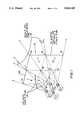
- FIG. 3shows a camera system which includes an apparatus in accordance with the principles of the present invention for developing the sub-fields shown in FIG. 2;
- FIG. 4illustrates the camera system of FIG. 3 as viewed from a position along the optical axis of the field of view
- FIG. 5illustrates a view of the camera system of FIG. 3 taken along the line AA' of FIG. 4;
- FIG. 6shows a system for simultaneously combining and displaying the sub-fields developed by the camera system of FIGS. 3-5 to reconstruct the field of view and image;
- FIG. 7shows a schematic representation of a system for forming an HDTV signal based upon the signals developed by the camera system of FIGS. 3-5.
- FIG. 1four separate cameras or camera targets 1, 2, 3 and 4 having separate focal points view four sub-fields 5, 6, 7 and 8 of a field of view 101 which is bounded by points 10, 12, 14 and 16.
- the field of view 101is in a plane 19 which is perpendicular to the optical axes or lines-of-sight of the camera targets.
- sub-field 5is bounded by points 15, 16 17, and 18, sub-field 6 by points 18, 17, 10 and 11, sub-field 7 by points 13, 18 11, and 12 and sub-field 8 by points 14, 15, 18 and 13.
- the sub-fields 5-8are contiguous only in the plane 19. In planes forward of plane 19, the sub-fields 5-8 overlap as is shown at locations 21. In planes in back of plane 19, gaps appear between the sub-fields 5-8 as is shown at locations 20. Therefore, the practical use of the camera system of FIG. 1 for developing sub-fields of a field of view for use in high resolution image reproduction is extremely limited, since only sub-fields located within the single plane 19 can be merged to reconstruct the field of view without degradation.
- FIG. 2illustrates four sub-fields 5', 6', 7' and 8' of a field of view 101 developed by four camera targets having a common focal point 22.
- the sub-fields 5' to 8'are contiguous and non-overlapping, with the sub-field 5' bounded by points 15', 16', 17', and 18', the sub-field 6' by points 18', 17', 10' and 11', the sub-field 7' by points 13', 18', 11' and 12' and the sub-field 8' by points 14', 15', 18' and 13'.
- the sub-fields 5'-8'have a common focal point, however, the sub-fields are not only contiguous, and non-overlapping in plane 19', but in all other parallel planes in front of and in back of the plane 19. As a result, regardless of the plane in which the field of view 101' lies, the developed sub-fields 5'-8' can be recombined to reproduce the field of view 101' without degradation.
- a camera system capable of developing the sub-fields of FIG. 2offers a much more attractive mechanism for high resolution reproduction than the camera system of FIG. 1.
- FIGS. 3-5illustrate a compact camera system in accordance with the principles of the present invention for realizing the sub-fields of FIG. 2. More particularly, as shown, the camera system comprises a lens 39 which captures a field of view 41 and conveys it to a reflective or mirror element 40. The mirror element 40 then segments the field of view into four contiguous, non-overlapping vertical and horizontal sub-fields 23-26.
- element 40is a pyramid shaped element having mirrored or reflective facets 35-38 which, in the case shown, are four in number.
- the element 40is situated with its apex 42 and its axis 42a along the line-of-sight or optical axis 39a of the lens 39.
- the element 40is further characterized, in the illustrative case, by having a square base 45 and each facet 35-38 set at a forty-five degree angle with respect to the base.
- the reflective facets 35-38have the focal point of the lens as a common focal point and each is able to develop one of the contiguous, non-overlapping sub-fields 23-26.
- the developed sub-fields 23-26are then reflected by their respective facets and directed to respective flat reflective elements or mirrors 27-30.
- Each mirror 27-30is aligned parallel to its respective facet 35-38 and directs the received sub-field to one of four camera targets 31-34 of the camera system. These targets are positioned parallel to the base 45 of the reflective element 40.
- the camera system targetsreceive contiguous, non-overlapping sub-fields of the field of view.
- FIG. 4the camera system of FIG. 3 is shown as viewed from a position along the lens optical axis 39.
- the optical axisis projected perpendicular to the paper and each of the sub-fields 23-26 are shown as they reach the central mirror element 40.
- the diagonal axes of the base 45 of the element 40align with the horizontal and vertical innermost edges of the sub-fields.
- FIG. 5which is a cross sectional view along the line AA' in FIG. 4, more clearly shows this.
- the optical ray 43 at the innermost corner of the sub-field 23, which ray is along the optical axis 39,is displaced by reflective facet 35 to the flat mirror 27.
- the mirror 27then reflects the ray so that it clears the base 45 of the element 40 and is, therefore, able to reach the camera target 31.
- a second optical ray 44, representing the outermost corner of the sub-field 23,is also shown. This ray is displaced by reflective facet 35 and mirror 27 so that it also reaches the camera target 31.
- a continuum of all other rays (not shown) from the sub-field 23are likewise reflected by the facet 35 and mirror 27 onto the camera target 31.
- each camera target 31-34 along the optical axisis determined by the size of the camera target. A smaller camera target will be place further away from the base 45 and a larger camera target placed closer to the base 45 (as measured along the optical axis.)
- each sub-fieldis reflected by two surfaces, i.e., a facet and a corresponding flat mirror, in the path of the sub-field.
- Each sub-fieldis, therefore, reversed twice resulting in the preservation of the sub-field's orientation.
- the camera system of FIGS. 3-5is advantageous in enabling the recording of contiguous, non-overlapping vertical and horizontal sub-fields with a high degree of precision and in a physically compact assembly, limited only by the aforementioned distance requirement between the facets and the flat surface mirrors. Additionally, the use of mirrors for reflecting the sub-fields avoids both refraction and attenuation as can occur with prisms and lenses. Also, the relative alignment between the lens 39, the facets 35-38 and the mirrors 27-30 remains fixed, thereby avoiding the need to adjust these components relative to each other. The only adjustment necessary might be adjusting the positioning of the edges of the camera targets which can be readily achieved either electrically or electromechanically. Finally, once the camera targets have been aligned, any lens of sufficient size and focal length can be used for the lens 39 to focus the field onto the targets without necessitating realignment.
- each camera targetupon receiving its sub-field converts the image received into an electrical signal which can be read by scanning the target.
- Conventional scanning equipmentis included in the camera systems of FIGS. 3-5 for this purpose, as schematically illustrated by the scanning mechanism 105 in FIG. 5.
- a typical type of target used for the camera targets 31-34might be a video camera target whose surface material develops an electrical charge pattern based on the received image.
- CRT video type camera targetselectron beam scanning equipment would be used to scan the charge pattern and develop a corresponding electrical signal.
- FIG. 6a system for simultaneously displaying the images of the sub-fields captured by the four camera targets 31-34 of the camera system of the invention is shown.
- the electrical signals obtained from scanning the camera targets 31-34are provided to respective projectors 49-52.
- the projectors 49-52are positioned so that the projected sub-field images 54-57 are closely adjacent to each other in both the horizontal and vertical direction.
- the composite image 53 formed by the four sub-fields 54-57is thus a reproduction of the image of the field of view 41 viewed by the camera system.
- the resolution of the projected imagewill be greater than the resolution obtained if a single camera target and a single projector were used to reproduce the same field of view, since each sub-field has the resolution of a single camera/single projector combination.
- each sub-field projection 54-57indicate the directions in which the corresponding camera targets should be scanned to prevent degradation of the image at the inner boundaries of the sub-fields due to movement across the boundaries.
- This order of scanning in recording imagesis required because the scanning of a frame of the image on a target takes a finite amount of time. If adjacent elements on opposite sides of a sub-field boundary are not scanned and displayed at close to the same instant, then motion of an object across the boundary will not be smooth.
- the scanning order in recording images illustratedassures that elements near the boundaries are displayed at the same time or very close to the same time, thus preventing moving objects from rendering the boundary visible.
- FIG. 7illustrates an HDTV system which has been adapted for use with the camera system of the present invention so as to enable the HDTV system to provide 1050 progressively scanned lines at a frame rate of 60 frames a second. While HDTV systems providing 525 progressively scanned lines at 60 frames a second have been achieved to date, systems having 1050 lines have not been achieved due to the limitations on the ability to scan available targets.
- the contiguous, non-overlapping sub-field images (not shown) captured by camera targets 31-34 of the camera system of the inventionare progressively scanned at a 525 line sixty frame per second rate by corresponding conventional analog scanning circuits 60-63. This scanning is done in the directions of arrows 75 in order to preserve image integrity at the inner boundaries as above-described.
- the analog outputs 72-75 from the circuits 60-63are then converted by corresponding analog to digital (A/D) converters 64-67 to digital representations and stored in corresponding locations 68-71 in a line frame buffer 72.
- the contents of the line frame buffer 72are then read out sequentially by a conventional read out device to produce a 1050 line, sixty frames per second progressively scanned HDTV signal.
- the system of FIG. 7is able circumvent the limitations of present camera target technology in order to construct a sixty frame per second, 1050 line, HDTV system not otherwise attainable.
Landscapes
- Physics & Mathematics (AREA)
- Engineering & Computer Science (AREA)
- Multimedia (AREA)
- Signal Processing (AREA)
- General Physics & Mathematics (AREA)
- Optics & Photonics (AREA)
- Stereoscopic And Panoramic Photography (AREA)
- Transforming Light Signals Into Electric Signals (AREA)
Abstract
Description
Claims (33)
Priority Applications (1)
| Application Number | Priority Date | Filing Date | Title |
|---|---|---|---|
| US07/547,825US5016109A (en) | 1990-07-02 | 1990-07-02 | Apparatus and method for segmenting a field of view into contiguous, non-overlapping, vertical and horizontal sub-fields |
Applications Claiming Priority (1)
| Application Number | Priority Date | Filing Date | Title |
|---|---|---|---|
| US07/547,825US5016109A (en) | 1990-07-02 | 1990-07-02 | Apparatus and method for segmenting a field of view into contiguous, non-overlapping, vertical and horizontal sub-fields |
Publications (1)
| Publication Number | Publication Date |
|---|---|
| US5016109Atrue US5016109A (en) | 1991-05-14 |
Family
ID=24186295
Family Applications (1)
| Application Number | Title | Priority Date | Filing Date |
|---|---|---|---|
| US07/547,825Expired - LifetimeUS5016109A (en) | 1990-07-02 | 1990-07-02 | Apparatus and method for segmenting a field of view into contiguous, non-overlapping, vertical and horizontal sub-fields |
Country Status (1)
| Country | Link |
|---|---|
| US (1) | US5016109A (en) |
Cited By (60)
| Publication number | Priority date | Publication date | Assignee | Title |
|---|---|---|---|---|
| US5157499A (en)* | 1990-06-29 | 1992-10-20 | Kabushiki Kaisha N A C | High-speed video camera using solid-state image sensor |
| US5194959A (en)* | 1989-12-21 | 1993-03-16 | Ricoh Company, Ltd. and Nippon Telegraph and Telephone Corporation | Image forming apparatus for forming image corresponding to subject, by dividing optical image corresponding to the subject into plural adjacent optical image parts |
| FR2694428A1 (en)* | 1992-08-03 | 1994-02-04 | Asahi Optical Co Ltd | Image signal processing device. |
| WO1994014275A1 (en)* | 1992-12-10 | 1994-06-23 | British Broadcasting Corporation | Higher definition video signals from lower definition sources |
| EP0618719A1 (en)* | 1993-03-30 | 1994-10-05 | Koninklijke Philips Electronics N.V. | X-ray examination apparatus with an imaging arrangement having a plurality of image sensors |
| US5532737A (en)* | 1993-05-03 | 1996-07-02 | Bell Communications Research, Inc. | Camera arrangement with wide field of view |
| US5539483A (en)* | 1995-06-30 | 1996-07-23 | At&T Corp. | Panoramic projection apparatus |
| US5591955A (en)* | 1993-05-11 | 1997-01-07 | Laser; Vadim | Portable data file readers |
| US5689302A (en)* | 1992-12-10 | 1997-11-18 | British Broadcasting Corp. | Higher definition video signals from lower definition sources |
| US5745305A (en)* | 1995-04-28 | 1998-04-28 | Lucent Technologies Inc. | Panoramic viewing apparatus |
| US5757424A (en)* | 1995-12-19 | 1998-05-26 | Xerox Corporation | High-resolution video conferencing system |
| US5793527A (en)* | 1995-06-30 | 1998-08-11 | Lucent Technologies Inc. | High resolution viewing system |
| US5835278A (en)* | 1990-11-06 | 1998-11-10 | Rubin; Leoind Borisovich | Optical system for partitioning a real image |
| US5870135A (en)* | 1995-07-27 | 1999-02-09 | Sensormatic Electronics Corporation | Image splitting forming and processing device and method for use with no moving parts camera |
| US5990934A (en)* | 1995-04-28 | 1999-11-23 | Lucent Technologies, Inc. | Method and system for panoramic viewing |
| US6005721A (en)* | 1997-09-26 | 1999-12-21 | Bodenseewerk Geratetechnik Gmbh | Device for observing a plurality of fields of view by means of an image resolving detector |
| ES2138562A1 (en)* | 1997-03-21 | 2000-01-01 | Manzanares Jesus Mari Gonzalez | Electronic projection cinema via satellite |
| US6043837A (en)* | 1997-05-08 | 2000-03-28 | Be Here Corporation | Method and apparatus for electronically distributing images from a panoptic camera system |
| US6111702A (en)* | 1995-11-30 | 2000-08-29 | Lucent Technologies Inc. | Panoramic viewing system with offset virtual optical centers |
| US6115176A (en)* | 1995-11-30 | 2000-09-05 | Lucent Technologies Inc. | Spherical viewing/projection apparatus |
| US6128143A (en)* | 1998-08-28 | 2000-10-03 | Lucent Technologies Inc. | Panoramic viewing system with support stand |
| US6141145A (en)* | 1998-08-28 | 2000-10-31 | Lucent Technologies | Stereo panoramic viewing system |
| US6144501A (en)* | 1998-08-28 | 2000-11-07 | Lucent Technologies Inc. | Split mirrored panoramic image display |
| US6195204B1 (en) | 1998-08-28 | 2001-02-27 | Lucent Technologies Inc. | Compact high resolution panoramic viewing system |
| US6205406B1 (en)* | 1998-05-01 | 2001-03-20 | Auto Image Id, Inc. | Optical scanner alignment indicator method and apparatus |
| US6285365B1 (en) | 1998-08-28 | 2001-09-04 | Fullview, Inc. | Icon referenced panoramic image display |
| US6313865B1 (en) | 1997-05-08 | 2001-11-06 | Be Here Corporation | Method and apparatus for implementing a panoptic camera system |
| US20020054217A1 (en)* | 2000-11-07 | 2002-05-09 | Minolta Co., Ltd. | Method for connecting split images and image shooting apparatus |
| US6459451B2 (en) | 1996-06-24 | 2002-10-01 | Be Here Corporation | Method and apparatus for a panoramic camera to capture a 360 degree image |
| WO2002085000A1 (en)* | 2001-04-13 | 2002-10-24 | The Trustees Of Columbia University In The City Of New York | Method and apparatus for recording a sequence of images using a moving optical element |
| US20030138247A1 (en)* | 2000-07-14 | 2003-07-24 | Michael Trunz | Camera system having at least two first cameras and two second cameras |
| US20040004614A1 (en)* | 2002-02-22 | 2004-01-08 | Bacus Laboratories, Inc. | Focusable virtual microscopy apparatus and method |
| US20040012689A1 (en)* | 2002-07-16 | 2004-01-22 | Fairchild Imaging | Charge coupled devices in tiled arrays |
| US20040012688A1 (en)* | 2002-07-16 | 2004-01-22 | Fairchild Imaging | Large area charge coupled device camera |
| US20040012684A1 (en)* | 2002-07-16 | 2004-01-22 | Fairchild Imaging | Image reconstruction techniques for charge coupled devices |
| WO2005038503A1 (en) | 2003-10-21 | 2005-04-28 | Atmel Grenoble | Compact photographing device |
| US20060066730A1 (en)* | 2004-03-18 | 2006-03-30 | Evans Daniel B Jr | Multi-camera image stitching for a distributed aperture system |
| EP0862748B2 (en)† | 1995-11-24 | 2006-05-24 | Swissray Medical AG | Optical arrangement and method for electronically detecting an x-ray image |
| US20060215038A1 (en)* | 2001-05-04 | 2006-09-28 | Gruber Michael A | Large format camera systems |
| WO2006095344A3 (en)* | 2005-03-08 | 2007-11-01 | Rafael Armament Dev Authority | System and method for wide angle optical surveillance |
| US20080137074A1 (en)* | 2006-11-28 | 2008-06-12 | Negevtech, Ltd. | Image Splitting in Optical Inspection Systems |
| US20080137073A1 (en)* | 2006-11-28 | 2008-06-12 | Negevtech, Ltd. | Image Splitting in Optical Inspection Systems |
| US7463280B2 (en) | 2003-06-03 | 2008-12-09 | Steuart Iii Leonard P | Digital 3D/360 degree camera system |
| US20090196400A1 (en)* | 2008-02-06 | 2009-08-06 | Fraunhofer-Gesellschaft Zur Foerderung Der Angewandten Forschung E.V. | Apparatus and method for detecting an image |
| WO2009098014A3 (en)* | 2008-02-06 | 2010-02-25 | Fraunhofer-Gesellschaft zur Förderung der angewandten Forschung e.V. | Device and method for recording an image |
| US20120105593A1 (en)* | 2010-10-29 | 2012-05-03 | Sony Corporation | Multi-view video and still 3d capture system |
| WO2014062481A1 (en)* | 2012-10-19 | 2014-04-24 | Qualcomm Incorporated | Multi-camera system using folded optics |
| US9294672B2 (en) | 2014-06-20 | 2016-03-22 | Qualcomm Incorporated | Multi-camera system using folded optics free from parallax and tilt artifacts |
| US9374516B2 (en) | 2014-04-04 | 2016-06-21 | Qualcomm Incorporated | Auto-focus in low-profile folded optics multi-camera system |
| US9383550B2 (en) | 2014-04-04 | 2016-07-05 | Qualcomm Incorporated | Auto-focus in low-profile folded optics multi-camera system |
| US9386222B2 (en) | 2014-06-20 | 2016-07-05 | Qualcomm Incorporated | Multi-camera system using folded optics free from parallax artifacts |
| US9438889B2 (en) | 2011-09-21 | 2016-09-06 | Qualcomm Incorporated | System and method for improving methods of manufacturing stereoscopic image sensors |
| US9485495B2 (en) | 2010-08-09 | 2016-11-01 | Qualcomm Incorporated | Autofocus for stereo images |
| US9541740B2 (en) | 2014-06-20 | 2017-01-10 | Qualcomm Incorporated | Folded optic array camera using refractive prisms |
| US9549107B2 (en) | 2014-06-20 | 2017-01-17 | Qualcomm Incorporated | Autofocus for folded optic array cameras |
| US9819863B2 (en) | 2014-06-20 | 2017-11-14 | Qualcomm Incorporated | Wide field of view array camera for hemispheric and spherical imaging |
| US9832381B2 (en) | 2014-10-31 | 2017-11-28 | Qualcomm Incorporated | Optical image stabilization for thin cameras |
| US10013764B2 (en) | 2014-06-19 | 2018-07-03 | Qualcomm Incorporated | Local adaptive histogram equalization |
| US20180356216A1 (en)* | 2016-02-23 | 2018-12-13 | Boe Technology Group Co., Ltd. | Distance measuring module, three-dimensional (3d) scanning system and distance measuring method |
| US10178373B2 (en) | 2013-08-16 | 2019-01-08 | Qualcomm Incorporated | Stereo yaw correction using autofocus feedback |
Citations (13)
| Publication number | Priority date | Publication date | Assignee | Title |
|---|---|---|---|---|
| US1887650A (en)* | 1926-05-27 | 1932-11-15 | Chester W Larner | Light controlling apparatus |
| US2219149A (en)* | 1937-02-06 | 1940-10-22 | Alfred N Goldsmith | Television system |
| US2267813A (en)* | 1938-11-05 | 1941-12-30 | Gen Electric | Multicathode ray electrode assembly |
| US3118340A (en)* | 1964-01-21 | Panoramic motion picture camera arrangement | ||
| US3602571A (en)* | 1968-12-03 | 1971-08-31 | Westinghouse Electric Corp | Optical beam scanner providing angular displacements of large beam diameters over wide fields of view |
| US3602572A (en)* | 1968-12-03 | 1971-08-31 | Westinghouse Electric Corp | Two-dimensional optical beam scanner |
| US3983328A (en)* | 1975-03-07 | 1976-09-28 | Westinghouse Electric Corporation | Television system for the display of visuals with high resolution |
| US4056827A (en)* | 1974-10-30 | 1977-11-01 | Redifon Limited | Optical systems for the display of visual images |
| US4078860A (en)* | 1976-10-27 | 1978-03-14 | Globus Ronald P | Cycloramic image projection system |
| US4323925A (en)* | 1980-07-07 | 1982-04-06 | Avco Everett Research Laboratory, Inc. | Method and apparatus for arraying image sensor modules |
| US4373169A (en)* | 1979-10-30 | 1983-02-08 | The Boeing Company | Multi-window visual display system for flight simulators |
| US4660096A (en)* | 1984-12-11 | 1987-04-21 | Rca Corporation | Dividing high-resolution-camera video signal response into sub-image blocks individually raster scanned |
| US4890314A (en)* | 1988-08-26 | 1989-12-26 | Bell Communications Research, Inc. | Teleconference facility with high resolution video display |
- 1990
- 1990-07-02USUS07/547,825patent/US5016109A/ennot_activeExpired - Lifetime
Patent Citations (13)
| Publication number | Priority date | Publication date | Assignee | Title |
|---|---|---|---|---|
| US3118340A (en)* | 1964-01-21 | Panoramic motion picture camera arrangement | ||
| US1887650A (en)* | 1926-05-27 | 1932-11-15 | Chester W Larner | Light controlling apparatus |
| US2219149A (en)* | 1937-02-06 | 1940-10-22 | Alfred N Goldsmith | Television system |
| US2267813A (en)* | 1938-11-05 | 1941-12-30 | Gen Electric | Multicathode ray electrode assembly |
| US3602571A (en)* | 1968-12-03 | 1971-08-31 | Westinghouse Electric Corp | Optical beam scanner providing angular displacements of large beam diameters over wide fields of view |
| US3602572A (en)* | 1968-12-03 | 1971-08-31 | Westinghouse Electric Corp | Two-dimensional optical beam scanner |
| US4056827A (en)* | 1974-10-30 | 1977-11-01 | Redifon Limited | Optical systems for the display of visual images |
| US3983328A (en)* | 1975-03-07 | 1976-09-28 | Westinghouse Electric Corporation | Television system for the display of visuals with high resolution |
| US4078860A (en)* | 1976-10-27 | 1978-03-14 | Globus Ronald P | Cycloramic image projection system |
| US4373169A (en)* | 1979-10-30 | 1983-02-08 | The Boeing Company | Multi-window visual display system for flight simulators |
| US4323925A (en)* | 1980-07-07 | 1982-04-06 | Avco Everett Research Laboratory, Inc. | Method and apparatus for arraying image sensor modules |
| US4660096A (en)* | 1984-12-11 | 1987-04-21 | Rca Corporation | Dividing high-resolution-camera video signal response into sub-image blocks individually raster scanned |
| US4890314A (en)* | 1988-08-26 | 1989-12-26 | Bell Communications Research, Inc. | Teleconference facility with high resolution video display |
Cited By (109)
| Publication number | Priority date | Publication date | Assignee | Title |
|---|---|---|---|---|
| US5194959A (en)* | 1989-12-21 | 1993-03-16 | Ricoh Company, Ltd. and Nippon Telegraph and Telephone Corporation | Image forming apparatus for forming image corresponding to subject, by dividing optical image corresponding to the subject into plural adjacent optical image parts |
| US5157499A (en)* | 1990-06-29 | 1992-10-20 | Kabushiki Kaisha N A C | High-speed video camera using solid-state image sensor |
| US5835278A (en)* | 1990-11-06 | 1998-11-10 | Rubin; Leoind Borisovich | Optical system for partitioning a real image |
| FR2694428A1 (en)* | 1992-08-03 | 1994-02-04 | Asahi Optical Co Ltd | Image signal processing device. |
| WO1994014275A1 (en)* | 1992-12-10 | 1994-06-23 | British Broadcasting Corporation | Higher definition video signals from lower definition sources |
| US5689302A (en)* | 1992-12-10 | 1997-11-18 | British Broadcasting Corp. | Higher definition video signals from lower definition sources |
| EP0618719A1 (en)* | 1993-03-30 | 1994-10-05 | Koninklijke Philips Electronics N.V. | X-ray examination apparatus with an imaging arrangement having a plurality of image sensors |
| US5532737A (en)* | 1993-05-03 | 1996-07-02 | Bell Communications Research, Inc. | Camera arrangement with wide field of view |
| US5591955A (en)* | 1993-05-11 | 1997-01-07 | Laser; Vadim | Portable data file readers |
| US5745305A (en)* | 1995-04-28 | 1998-04-28 | Lucent Technologies Inc. | Panoramic viewing apparatus |
| US5990934A (en)* | 1995-04-28 | 1999-11-23 | Lucent Technologies, Inc. | Method and system for panoramic viewing |
| US5539483A (en)* | 1995-06-30 | 1996-07-23 | At&T Corp. | Panoramic projection apparatus |
| US5793527A (en)* | 1995-06-30 | 1998-08-11 | Lucent Technologies Inc. | High resolution viewing system |
| US5870135A (en)* | 1995-07-27 | 1999-02-09 | Sensormatic Electronics Corporation | Image splitting forming and processing device and method for use with no moving parts camera |
| EP0862748B2 (en)† | 1995-11-24 | 2006-05-24 | Swissray Medical AG | Optical arrangement and method for electronically detecting an x-ray image |
| US6219090B1 (en) | 1995-11-30 | 2001-04-17 | Lucent Technologies Inc. | Panoramic viewing system with offset virtual optical centers |
| US6356397B1 (en) | 1995-11-30 | 2002-03-12 | Fullview, Inc. | Panoramic viewing system with shades |
| US6111702A (en)* | 1995-11-30 | 2000-08-29 | Lucent Technologies Inc. | Panoramic viewing system with offset virtual optical centers |
| US6115176A (en)* | 1995-11-30 | 2000-09-05 | Lucent Technologies Inc. | Spherical viewing/projection apparatus |
| US5757424A (en)* | 1995-12-19 | 1998-05-26 | Xerox Corporation | High-resolution video conferencing system |
| US6459451B2 (en) | 1996-06-24 | 2002-10-01 | Be Here Corporation | Method and apparatus for a panoramic camera to capture a 360 degree image |
| ES2138562A1 (en)* | 1997-03-21 | 2000-01-01 | Manzanares Jesus Mari Gonzalez | Electronic projection cinema via satellite |
| US6043837A (en)* | 1997-05-08 | 2000-03-28 | Be Here Corporation | Method and apparatus for electronically distributing images from a panoptic camera system |
| US6356296B1 (en) | 1997-05-08 | 2002-03-12 | Behere Corporation | Method and apparatus for implementing a panoptic camera system |
| US6313865B1 (en) | 1997-05-08 | 2001-11-06 | Be Here Corporation | Method and apparatus for implementing a panoptic camera system |
| US6219089B1 (en) | 1997-05-08 | 2001-04-17 | Be Here Corporation | Method and apparatus for electronically distributing images from a panoptic camera system |
| US6005721A (en)* | 1997-09-26 | 1999-12-21 | Bodenseewerk Geratetechnik Gmbh | Device for observing a plurality of fields of view by means of an image resolving detector |
| US6205406B1 (en)* | 1998-05-01 | 2001-03-20 | Auto Image Id, Inc. | Optical scanner alignment indicator method and apparatus |
| US6195204B1 (en) | 1998-08-28 | 2001-02-27 | Lucent Technologies Inc. | Compact high resolution panoramic viewing system |
| US6144501A (en)* | 1998-08-28 | 2000-11-07 | Lucent Technologies Inc. | Split mirrored panoramic image display |
| US6141145A (en)* | 1998-08-28 | 2000-10-31 | Lucent Technologies | Stereo panoramic viewing system |
| US6285365B1 (en) | 1998-08-28 | 2001-09-04 | Fullview, Inc. | Icon referenced panoramic image display |
| US6128143A (en)* | 1998-08-28 | 2000-10-03 | Lucent Technologies Inc. | Panoramic viewing system with support stand |
| US6834163B2 (en)* | 2000-07-14 | 2004-12-21 | Z/I Imaging Gmbh | Camera system having at least two first cameras and two second cameras |
| US20030138247A1 (en)* | 2000-07-14 | 2003-07-24 | Michael Trunz | Camera system having at least two first cameras and two second cameras |
| US20020054217A1 (en)* | 2000-11-07 | 2002-05-09 | Minolta Co., Ltd. | Method for connecting split images and image shooting apparatus |
| US7184091B2 (en)* | 2000-11-07 | 2007-02-27 | Minolta Co., Ltd. | Method for connecting split images and image shooting apparatus |
| WO2002085000A1 (en)* | 2001-04-13 | 2002-10-24 | The Trustees Of Columbia University In The City Of New York | Method and apparatus for recording a sequence of images using a moving optical element |
| US7554596B2 (en) | 2001-04-13 | 2009-06-30 | The Trustees Of Columbia University In The City Of New York | Method and apparatus for recording a sequence of images using a moving optical element |
| US20050041113A1 (en)* | 2001-04-13 | 2005-02-24 | Nayar Shree K. | Method and apparatus for recording a sequence of images using a moving optical element |
| US20060215038A1 (en)* | 2001-05-04 | 2006-09-28 | Gruber Michael A | Large format camera systems |
| US7339614B2 (en)* | 2001-05-04 | 2008-03-04 | Microsoft Corporation | Large format camera system with multiple coplanar focusing systems |
| US7925067B2 (en) | 2002-02-22 | 2011-04-12 | Olympus America Inc. | Focusable virtual microscopy apparatus and method |
| US20110181622A1 (en)* | 2002-02-22 | 2011-07-28 | Olympus America Inc. | Focusable virtual microscopy apparatus and method |
| US20040004614A1 (en)* | 2002-02-22 | 2004-01-08 | Bacus Laboratories, Inc. | Focusable virtual microscopy apparatus and method |
| US20100074489A1 (en)* | 2002-02-22 | 2010-03-25 | Olympus America Inc. | Focusable virtual microscopy apparatus and method |
| US7596249B2 (en)* | 2002-02-22 | 2009-09-29 | Olympus America Inc. | Focusable virtual microscopy apparatus and method |
| US8306300B2 (en) | 2002-02-22 | 2012-11-06 | Olympus America Inc. | Focusable virtual microscopy apparatus and method |
| US20040012689A1 (en)* | 2002-07-16 | 2004-01-22 | Fairchild Imaging | Charge coupled devices in tiled arrays |
| US20040012684A1 (en)* | 2002-07-16 | 2004-01-22 | Fairchild Imaging | Image reconstruction techniques for charge coupled devices |
| US20040012688A1 (en)* | 2002-07-16 | 2004-01-22 | Fairchild Imaging | Large area charge coupled device camera |
| US7463280B2 (en) | 2003-06-03 | 2008-12-09 | Steuart Iii Leonard P | Digital 3D/360 degree camera system |
| US8659640B2 (en) | 2003-06-03 | 2014-02-25 | Leonard P. Steuart, III | Digital 3D/360 ° camera system |
| US8937640B2 (en) | 2003-06-03 | 2015-01-20 | Leonard P. Steuart, III | Digital 3D/360 degree camera system |
| US8274550B2 (en) | 2003-06-03 | 2012-09-25 | Steuart Iii Leonard P Skip | Digital 3D/360 degree camera system |
| US9124802B2 (en) | 2003-06-03 | 2015-09-01 | Leonard P. Steuart, III | Digital 3D/360 degree camera system |
| US11012622B2 (en) | 2003-06-03 | 2021-05-18 | Leonard P. Steuart, III | Digital 3D/360 degree camera system |
| US10574888B2 (en) | 2003-06-03 | 2020-02-25 | Leonard P. Steuart, III | Digital 3D/360 degree camera system |
| US9706119B2 (en) | 2003-06-03 | 2017-07-11 | Leonard P. Steuart, III | Digital 3D/360 degree camera system |
| US10218903B2 (en) | 2003-06-03 | 2019-02-26 | Leonard P. Steuart, III | Digital 3D/360 degree camera system |
| WO2005038503A1 (en) | 2003-10-21 | 2005-04-28 | Atmel Grenoble | Compact photographing device |
| EP1676164A1 (en)* | 2003-10-21 | 2006-07-05 | Atmel Grenoble | Compact photographing device |
| WO2006022855A3 (en)* | 2004-03-18 | 2007-07-05 | Northrop Grumman Corp | Multi-camera image stitching for a distributed aperture system |
| US20060066730A1 (en)* | 2004-03-18 | 2006-03-30 | Evans Daniel B Jr | Multi-camera image stitching for a distributed aperture system |
| US7499079B2 (en)* | 2004-03-18 | 2009-03-03 | Northrop Grumman Corporation | Multi-camera image stitching for a distributed aperture system |
| US20080191127A1 (en)* | 2005-03-08 | 2008-08-14 | Rafael-Armament Development Authority Ltd. | System and Method for Wide Angle Optical Surveillance |
| GB2439230B (en)* | 2005-03-08 | 2010-09-29 | Rafael Armament Dev Authority | System and method for field-of-view switching for optical surveillance |
| WO2006095344A3 (en)* | 2005-03-08 | 2007-11-01 | Rafael Armament Dev Authority | System and method for wide angle optical surveillance |
| US7888644B2 (en)* | 2005-03-08 | 2011-02-15 | Rafael Advanced Defense Systems Ltd. | System and method for wide angle optical surveillance |
| US7564031B2 (en)* | 2005-03-08 | 2009-07-21 | Rafael Advanced Defence Systems Ltd. | System and method for wide angle optical surveillance |
| US20090179144A1 (en)* | 2005-03-08 | 2009-07-16 | Rafael Advanced Defense Systems Ltd. | System and method for wide angle optical surveillance |
| US7714998B2 (en)* | 2006-11-28 | 2010-05-11 | Applied Materials South East Asia Pte. Ltd. | Image splitting in optical inspection systems |
| US7719674B2 (en)* | 2006-11-28 | 2010-05-18 | Applied Materials South East Asia Pte. Ltd. | Image splitting in optical inspection systems |
| US20080137074A1 (en)* | 2006-11-28 | 2008-06-12 | Negevtech, Ltd. | Image Splitting in Optical Inspection Systems |
| US20080137073A1 (en)* | 2006-11-28 | 2008-06-12 | Negevtech, Ltd. | Image Splitting in Optical Inspection Systems |
| US7772561B2 (en) | 2008-02-06 | 2010-08-10 | Fraunhofer-Gesellschaft Zur Foerderung Der Angewandten Forschung E.V. | Apparatus and method for detecting an image |
| US20090196399A1 (en)* | 2008-02-06 | 2009-08-06 | Fraunhofer-Gesellschaft Zur Foerderung Der Angewandten Forschung E.V. | Apparatus and method for detecting an image |
| EP2293113A3 (en)* | 2008-02-06 | 2013-08-07 | Fraunhofer-Gesellschaft zur Förderung der Angewandten Forschung e.V. | Device and method for recording an image |
| US7807975B2 (en) | 2008-02-06 | 2010-10-05 | Fraunhofer-Gesellschaft Zur Foerderung Der Angewandten Forschung E.V. | Apparatus and method for detecting an image |
| CN101939667B (en)* | 2008-02-06 | 2013-03-20 | 弗劳恩霍夫应用研究促进协会 | Device and method for checking an image |
| WO2009098014A3 (en)* | 2008-02-06 | 2010-02-25 | Fraunhofer-Gesellschaft zur Förderung der angewandten Forschung e.V. | Device and method for recording an image |
| US20090196400A1 (en)* | 2008-02-06 | 2009-08-06 | Fraunhofer-Gesellschaft Zur Foerderung Der Angewandten Forschung E.V. | Apparatus and method for detecting an image |
| US9485495B2 (en) | 2010-08-09 | 2016-11-01 | Qualcomm Incorporated | Autofocus for stereo images |
| US20120105593A1 (en)* | 2010-10-29 | 2012-05-03 | Sony Corporation | Multi-view video and still 3d capture system |
| US8842168B2 (en)* | 2010-10-29 | 2014-09-23 | Sony Corporation | Multi-view video and still 3D capture system |
| US9438889B2 (en) | 2011-09-21 | 2016-09-06 | Qualcomm Incorporated | System and method for improving methods of manufacturing stereoscopic image sensors |
| CN104704809A (en)* | 2012-10-19 | 2015-06-10 | 高通股份有限公司 | Multi-camera system using folded optics |
| US9398264B2 (en) | 2012-10-19 | 2016-07-19 | Qualcomm Incorporated | Multi-camera system using folded optics |
| CN104704809B (en)* | 2012-10-19 | 2019-03-01 | 高通股份有限公司 | Multi-Camera System Using Folded Optics |
| US10165183B2 (en) | 2012-10-19 | 2018-12-25 | Qualcomm Incorporated | Multi-camera system using folded optics |
| WO2014062481A1 (en)* | 2012-10-19 | 2014-04-24 | Qualcomm Incorporated | Multi-camera system using folded optics |
| US9838601B2 (en) | 2012-10-19 | 2017-12-05 | Qualcomm Incorporated | Multi-camera system using folded optics |
| US10178373B2 (en) | 2013-08-16 | 2019-01-08 | Qualcomm Incorporated | Stereo yaw correction using autofocus feedback |
| US9860434B2 (en) | 2014-04-04 | 2018-01-02 | Qualcomm Incorporated | Auto-focus in low-profile folded optics multi-camera system |
| US9383550B2 (en) | 2014-04-04 | 2016-07-05 | Qualcomm Incorporated | Auto-focus in low-profile folded optics multi-camera system |
| US9374516B2 (en) | 2014-04-04 | 2016-06-21 | Qualcomm Incorporated | Auto-focus in low-profile folded optics multi-camera system |
| US9973680B2 (en) | 2014-04-04 | 2018-05-15 | Qualcomm Incorporated | Auto-focus in low-profile folded optics multi-camera system |
| US10013764B2 (en) | 2014-06-19 | 2018-07-03 | Qualcomm Incorporated | Local adaptive histogram equalization |
| US9854182B2 (en) | 2014-06-20 | 2017-12-26 | Qualcomm Incorporated | Folded optic array camera using refractive prisms |
| US9843723B2 (en) | 2014-06-20 | 2017-12-12 | Qualcomm Incorporated | Parallax free multi-camera system capable of capturing full spherical images |
| US10084958B2 (en) | 2014-06-20 | 2018-09-25 | Qualcomm Incorporated | Multi-camera system using folded optics free from parallax and tilt artifacts |
| US9819863B2 (en) | 2014-06-20 | 2017-11-14 | Qualcomm Incorporated | Wide field of view array camera for hemispheric and spherical imaging |
| US9733458B2 (en) | 2014-06-20 | 2017-08-15 | Qualcomm Incorporated | Multi-camera system using folded optics free from parallax artifacts |
| US9549107B2 (en) | 2014-06-20 | 2017-01-17 | Qualcomm Incorporated | Autofocus for folded optic array cameras |
| US9541740B2 (en) | 2014-06-20 | 2017-01-10 | Qualcomm Incorporated | Folded optic array camera using refractive prisms |
| US9386222B2 (en) | 2014-06-20 | 2016-07-05 | Qualcomm Incorporated | Multi-camera system using folded optics free from parallax artifacts |
| US9294672B2 (en) | 2014-06-20 | 2016-03-22 | Qualcomm Incorporated | Multi-camera system using folded optics free from parallax and tilt artifacts |
| US9832381B2 (en) | 2014-10-31 | 2017-11-28 | Qualcomm Incorporated | Optical image stabilization for thin cameras |
| US20180356216A1 (en)* | 2016-02-23 | 2018-12-13 | Boe Technology Group Co., Ltd. | Distance measuring module, three-dimensional (3d) scanning system and distance measuring method |
Similar Documents
| Publication | Publication Date | Title |
|---|---|---|
| US5016109A (en) | Apparatus and method for segmenting a field of view into contiguous, non-overlapping, vertical and horizontal sub-fields | |
| US4940309A (en) | Tessellator | |
| US4485406A (en) | Film video player with zoom and scan | |
| US9503638B1 (en) | High-resolution single-viewpoint panoramic camera and method of obtaining high-resolution panoramic images with a single viewpoint | |
| US4290083A (en) | Stereoscopic television (unaided) on standard bandwidth-method and apparatus | |
| US5180912A (en) | Display system with means for variably deflecting an array of optical emitters | |
| KR101168776B1 (en) | Image pickup device | |
| US3113180A (en) | Composite image reproducing means | |
| US4231642A (en) | Stereoscopic motion picture-circular to linear scan translator-method and apparatus | |
| EP0397647A1 (en) | Film to video transfer method. | |
| US6072627A (en) | Stereoscopic image capture device | |
| US20210286157A1 (en) | A Detachable Optical Structure for Displacing the Optical Axis of a Camera Device | |
| JP2007102201A (en) | 3D beam input device | |
| US4349252A (en) | Stereoscopic motion picture-circular to linear scan translator (alternate screen)-method and apparatus | |
| JPS61121668A (en) | Video camera | |
| CA1146260A (en) | Stereoscopic television(unaided) on standard bandwidth method and apparatus | |
| US3564128A (en) | Multiple scan optical recording apparatus | |
| US20100289881A1 (en) | Camera for multiple perspective image capturing | |
| US4306252A (en) | Optical scanning method and apparatus | |
| US5291018A (en) | Robigon and sinugon; detector geometries | |
| EP0757273A1 (en) | Combination of several viewing devices with common point of vision | |
| JPS59126378A (en) | Imaging device | |
| US4676613A (en) | Stereoscopic pictures using astigmatic low f-number projection lenses-method and apparatus | |
| JPH027681A (en) | television imaging device | |
| JPH11127375A (en) | Panoramic imaging device |
Legal Events
| Date | Code | Title | Description |
|---|---|---|---|
| AS | Assignment | Owner name:BELL SOUTH CORPORATION, A CORP. OF DE, GEORGIA Free format text:ASSIGNMENT OF ASSIGNORS INTEREST.;ASSIGNOR:GAYLORD, WILLIAM J.;REEL/FRAME:005376/0027 Effective date:19900626 | |
| STCF | Information on status: patent grant | Free format text:PATENTED CASE | |
| FEPP | Fee payment procedure | Free format text:PAYOR NUMBER ASSIGNED (ORIGINAL EVENT CODE: ASPN); ENTITY STATUS OF PATENT OWNER: LARGE ENTITY | |
| FPAY | Fee payment | Year of fee payment:4 | |
| FPAY | Fee payment | Year of fee payment:8 | |
| AS | Assignment | Owner name:BELLSOUTH INTELLECTUAL PROPERTY GROUP, INC., GEORG Free format text:ASSIGNMENT OF ASSIGNORS INTEREST;ASSIGNOR:BELLSOUTH CORPORATION;REEL/FRAME:009670/0482 Effective date:19980901 Owner name:BELLSOUTH INTELLECTUAL PROPERTY CORPORATION, DELAW Free format text:ASSIGNMENT OF ASSIGNORS INTEREST;ASSIGNOR:BELLSOUTH INTELLECTUAL PROPERTY GROUP, INC.;REEL/FRAME:009678/0367 Effective date:19980901 | |
| FPAY | Fee payment | Year of fee payment:12 |