US5014126A - Method and apparatus for recording images with a single image receiver for autostereoscopic display - Google Patents
Method and apparatus for recording images with a single image receiver for autostereoscopic displayDownload PDFInfo
- Publication number
- US5014126A US5014126AUS07/425,232US42523289AUS5014126AUS 5014126 AUS5014126 AUS 5014126AUS 42523289 AUS42523289 AUS 42523289AUS 5014126 AUS5014126 AUS 5014126A
- Authority
- US
- United States
- Prior art keywords
- scanning
- images
- recording
- convergence point
- along
- Prior art date
- Legal status (The legal status is an assumption and is not a legal conclusion. Google has not performed a legal analysis and makes no representation as to the accuracy of the status listed.)
- Expired - Lifetime
Links
Images


Classifications
- H—ELECTRICITY
- H04—ELECTRIC COMMUNICATION TECHNIQUE
- H04N—PICTORIAL COMMUNICATION, e.g. TELEVISION
- H04N13/00—Stereoscopic video systems; Multi-view video systems; Details thereof
- H—ELECTRICITY
- H04—ELECTRIC COMMUNICATION TECHNIQUE
- H04N—PICTORIAL COMMUNICATION, e.g. TELEVISION
- H04N13/00—Stereoscopic video systems; Multi-view video systems; Details thereof
- H04N13/30—Image reproducers
- H04N13/302—Image reproducers for viewing without the aid of special glasses, i.e. using autostereoscopic displays
- H04N13/31—Image reproducers for viewing without the aid of special glasses, i.e. using autostereoscopic displays using parallax barriers
- H04N13/315—Image reproducers for viewing without the aid of special glasses, i.e. using autostereoscopic displays using parallax barriers the parallax barriers being time-variant
- H—ELECTRICITY
- H04—ELECTRIC COMMUNICATION TECHNIQUE
- H04N—PICTORIAL COMMUNICATION, e.g. TELEVISION
- H04N13/00—Stereoscopic video systems; Multi-view video systems; Details thereof
- H04N13/10—Processing, recording or transmission of stereoscopic or multi-view image signals
- H04N13/189—Recording image signals; Reproducing recorded image signals
- H—ELECTRICITY
- H04—ELECTRIC COMMUNICATION TECHNIQUE
- H04N—PICTORIAL COMMUNICATION, e.g. TELEVISION
- H04N13/00—Stereoscopic video systems; Multi-view video systems; Details thereof
- H04N13/20—Image signal generators
- H04N13/204—Image signal generators using stereoscopic image cameras
- H04N13/207—Image signal generators using stereoscopic image cameras using a single 2D image sensor
- H—ELECTRICITY
- H04—ELECTRIC COMMUNICATION TECHNIQUE
- H04N—PICTORIAL COMMUNICATION, e.g. TELEVISION
- H04N13/00—Stereoscopic video systems; Multi-view video systems; Details thereof
- H04N13/30—Image reproducers
- H04N13/302—Image reproducers for viewing without the aid of special glasses, i.e. using autostereoscopic displays
- H—ELECTRICITY
- H04—ELECTRIC COMMUNICATION TECHNIQUE
- H04N—PICTORIAL COMMUNICATION, e.g. TELEVISION
- H04N13/00—Stereoscopic video systems; Multi-view video systems; Details thereof
- H04N13/20—Image signal generators
- H04N13/204—Image signal generators using stereoscopic image cameras
- H04N13/207—Image signal generators using stereoscopic image cameras using a single 2D image sensor
- H04N13/236—Image signal generators using stereoscopic image cameras using a single 2D image sensor using varifocal lenses or mirrors
- H—ELECTRICITY
- H04—ELECTRIC COMMUNICATION TECHNIQUE
- H04N—PICTORIAL COMMUNICATION, e.g. TELEVISION
- H04N13/00—Stereoscopic video systems; Multi-view video systems; Details thereof
- H04N13/20—Image signal generators
- H04N13/204—Image signal generators using stereoscopic image cameras
- H04N13/243—Image signal generators using stereoscopic image cameras using three or more 2D image sensors
- H—ELECTRICITY
- H04—ELECTRIC COMMUNICATION TECHNIQUE
- H04N—PICTORIAL COMMUNICATION, e.g. TELEVISION
- H04N13/00—Stereoscopic video systems; Multi-view video systems; Details thereof
- H04N13/20—Image signal generators
- H04N13/296—Synchronisation thereof; Control thereof
- H—ELECTRICITY
- H04—ELECTRIC COMMUNICATION TECHNIQUE
- H04N—PICTORIAL COMMUNICATION, e.g. TELEVISION
- H04N13/00—Stereoscopic video systems; Multi-view video systems; Details thereof
- H04N13/30—Image reproducers
- H04N13/332—Displays for viewing with the aid of special glasses or head-mounted displays [HMD]
- H04N13/334—Displays for viewing with the aid of special glasses or head-mounted displays [HMD] using spectral multiplexing
Definitions
- the present inventionrelates to apparatus and methods for recording a three-dimensional illusion and more specifically for recording images for truly autostereoscopic display.
- left and right eye informationcan be presented alternately to the left and right eyes, resulting in depth perception as long as the time interval does not exceed 100 ms. More recently, it has been demonstrated that stereoscopic information can be perceived by one eye if presented in the proper manner and it is possible for the brain to process and accept alternating parallax information, without regard to the direction of the parallax, from both eyes using a standard television screen.
- the two main categories for display hardwareare, stereoscopic and autostereoscopic.
- Stereoscopic techniquesrequire the viewer to wear some sort of apparatus to force each of the viewer's eyes to see a different perspective of the image.
- This groupincludes stereoscopes, polarization, anaglyphic, chromo-sterescopic, Pulfrich, and shuttering technologies.
- Autostereoscopic displaysdo not require viewing devices.
- Autostereoscopic displayincluding, among others, holography, lenticular screens, parallax barriers, and alternating pairs do not require the viewer to wear devices, but do require optical modifying display devices.
- True autostereoscopic displayrequire no special display device.
- the development of autostereoscopic methods and techniqueshas to some extent paralleled development in the field of physiology of depth perception.
- a principle drawback of alternating images from two viewing points, whether using horizontal, diagonal or vertical displacement approaches,is that slow moving or stationary objects in the scene being viewed tend to move or rock as the point of origin alternates. This image instability (rocking) phenomenon is attributable to the different viewing angles corresponding to the respective points of origin.
- the use of a single image receiverremoves all of the matching problems associated with a two camera method and practically allows the use of varifocal length (zoom) lens.
- a further object of this inventionis a method of blurring the background to enhance image stability without blurring the foreground.
- Another object to this inventionis a method of changing the view of the image receiver at a rate which is not closely related to the image recording rate.
- Still another object of this inventionis to provide apparatus for moving the image receiver or for manipulating the optical axis to simulate a moving image receiver.
- a further object of this inventionis to provide an additional depth cue by blurring the background.
- Still another object of the inventionis to provide a method of recording images for true autostereoscopic display with stable images.
- the method and apparatusincludes substantially continuously changing the view of a single image receiver substantially aligned to a convergent point in a scene along a scanning path and recording a plurality of scanning images for each cycle of traversing the scanning path.
- the optical length of views along the scanning path to the convergence pointis substantially constant to maintain an object at the convergence point substantially motionless during recording of the plural scanning images.
- the scanning pathis sufficiently short and the scanning rate is sufficient to produce motion, when displayed, which is within visio-psychological memory rate range.
- the scanning pathmay be an arc equidistant and centered on the convergence point and the image receiver is moved along rails tangent to the arc.
- the scanning pathcan also be an line segment sufficiently short such that all points along the line segment are substantially equidistant from the convergence point. For the line segment path, the image receiver is rotated simultaneous with moving along the scanning path for maintaining the objects at the convergence point substantially motionless.
- the single image receiver and the scenemay be moved relative to each other along the scanning path by: (A) moving the image receiver along the scanning path; (B) moving objects in the scene relative to the image receiver or (C) optically manipulating the optical path between the image receiver and the scene.
- the frequency of recording the scanning imageis independent of the rate of movement along the scanning path.
- the exposure time of the image receiveris set sufficiently along to produce the blurring of the objects in the scene not at the convergence point to enhance the effect.
- the scanning path and convergence pointare variable.
- the same effectmay be achieved by producing a plurality of images in a fixed medium from different views along the scanning path and optically recording the fixed mediums.
- a computeris used to generate a plurality of images at the various points of view along the scanning path and storing them for ultimate display.
- the apparatus for performing the methodincludes a single image receiver and a scanning apparatus for moving the optical axis of the image receiver and a scene relative to each other along a scanning path while maintaining the image receiver's optical axis substantially on a convergence point in the scene.
- a controlis provided for actuating the image receiver to record a plurality of scanning images, greater than 2, for each cycle of traversing of the scanning path so as to have a scanning motion.
- the scanning apparatusdefines the scanning path as an arc or a short line segment. If a short line segment defines the scanning path, the recorder is rotated simultaneously with movement along the scanning path.
- the scanning apparatusmay include a carriage mounted to a pair of rails which moves the image receiver along the scanning path or moves objects in the scene relative to a fix image receiver.
- the scanning apparatusmay optically manipulate the optical path to produce the scanning motion.
- the actuating deviceactuates the image receiver for exposure time sufficiently long to produce a blurring of the objects in the scene not at the convergence point.
- the actuating deviceactivates the image receiver at a frequency independent of the rate of the scanning.
- the rate of movementis adjustable.
- the actuation frequency and the rate of movement of the scanning apparatusproduce a motion of objects in the scene, when viewed, within the visio-psychological memory rate range.
- the scanning apparatushas the ability of changing the convergence point as well as the scanning path.
- FIG. 1is a view of the image scanning according to the principles of the present invention.
- FIG. 2is a graph of the scanning path with respect to a viewers axis verses time showing exposure regions.
- FIG. 3is a schematic view of a preferred scanning structure.
- FIG. 4is a schematic view of scanning apparatus for scanning by optical path manipulation with a fixed image receiver.
- FIG. 5is a schematically view of the scanning apparatus for scanning by motion control techniques.
- FIGS. 6a and 6bare schematic side and front views respectfully for an alternative embodiment of an image receiver moving along an arcuate scanning path.
- FIG. 7is a block diagram of a controller according to the present invention.
- FIG. 8is a block diagram of a system for computer generated images.
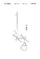
- FIG. 1illustrates the scanning geometry which produces the three-dimensional illusion.
- This figureshows a single image receiver 10 at three instantaneous views in the scanning path. Views 1 and 2 are at the ends of the scanning path while view 3 is at some intermediate position in the scanning path. These views lie along an arc 5 centered on a convergence point 6 and viewer axis 14 which represents the closest subject to the image receiver 10 per U.S. Pat. No. 4,815,819.
- the views 1, 2, and 3have optical paths 11, 12, and 13 which all pass through the convergence point 6 and extend to the background 15.
- the object at the convergence pointwill be substantially motionless and have only a slight rotational motion while the background will be having a scanning motion.
- the focal point of the image receiver 10is preferably in the background plane 15.
- FIG. 1exaggerates the angle between the extreme views 1 and 2. In practice this angle will be approximately one milliradian. Further, the arc segment 5 is then vary close to a straight line and may be approximated as a straight line if suitable means are employed keeping the image receiver 10 directed at the convergence point. The image receiver 10 should be rotated simultaneously with its movement along the path 5 for the reasons explained in U.S. Pat. No. 4,815,819.
- the extent of the scanning along the arc segment 5is a function of the distance from the image receiver to the convergence point as well as other motions in the scene and other image receiver or camera motions.
- FIG. 2is a graph of the scanning path about the viewer's axis 14 verses time showing the active image reception or open shutter in the clear areas and the closed shutter in the shaded areas.
- a viewwill be considered the length of time the shutter is open or the resulting recorder scanning image.
- the image receiver 10continuous moves along the scanning path 5 in an approximate sinusoidal motion as shown by curve 20 with zero velocity of the ends of the scanning path 5.
- the image receiver 10moves different amounts 21 and 22 for different views in the scanning path.
- These motionsblur the background and provide an additional depth cue while obscuring the scanning motion to enhance the apparent stability of the resulting recorded image.
- the prior artuses two cameras in fixed positions and alternates between the resulting sharp images at these two extreme positions. If the enhance effect of blurring is not desired and the equipment is available, the views along the scanning path can be substantially instantaneously recorded as if in stop motion.
- FIG. 2also shows that the exposure cycle is not necessarily related to the scanning cycle. Notice, the exposure 24 at the beginning of the first scanning cycle is not quite at the same position as the exposure 25 near the beginning of the second scan cycle. This asynchronous relationship further stabilizes the resulting recorded image. It may, however for special effects, be necessary to synchronize the scan rate with the exposure rate. Furthermore, the rate of the scan may be altered continuously or randomly to further stabilize the recorded image so long as the motion of objects in the scene when displayed remain in the visio-psychological memory rate.
- the scanning ratesare similar to the image changing cycle rates established for stereoscopic viewing in prior art, i.e. approximately 2 to 15 cycles per second.
- the image change ratesare equal to the image change rate of the medium; 24 for standard motion picture film, so for PAL video and 60 for NTSC video such that the recorded scanning images can be true autostereoscoptically displayed using standard display equipment.
- to produce a viewed image change rate of 8 cycles per second to be displayed by a standard motion picture camera at 24 cycles per secondrequires three images to be recorded per scanning cycles.
- the scanning path 5is substantially vertical since vertical parallax produces the appearance of depth while being more ameanable are comfortable to the viewer.
- the present methodis not restricted to only vertical paths.
- Path 5preferrably includes a vertical component and may include vertical as well as horizontal components. Although it is not necessarily preferred, it is within the scope of the present invention that scanning path 5 maybe totally horizontal.
- FIG. 1is a schematical representation of the method of the present invention and that the various scanning views of the scene along the path 5 may be produced by many different methods.
- the relative motion between the scene and the image receiver 10may be produced by moving the image receiver 10 along the path 5 as will be explained with respect to FIGS. 3, 6a and 6b.
- the optical path between the image receiver and the scenemay be optically manipulated to provide the different views along the scanning path as illustrated in FIG. 4.
- the image receivermay be fixed and the objects in the scene may be moved to produce the appropriate views along the scanning path.
- Another further alternative,is to use computer generated scenes at the various view along the scanning path and storing these electronically, as illustrated in FIG. 8.
- individual views of the scenes along the scanning pathmay be created and produced in a fixed medium and the fixed medium views recorded in a scanning sequence.
- FIG. 3shows the preferred scanning apparatus for moving an image receiver 34 relative to a scene.
- Dashed curve 30is the scanning arc about convergence point 31.
- Heavy line 32represents a mounting plate which moves along arc 30 via bearings 33 and supports image receiver 34.
- This assemblyis driven by a motor (not shown) to provide the approximate sinusoidal motion as depicted in FIG. 2. Travelling along a single arc reduces the usefulness to a single convergence distance.
- the rails 35 and 36are designed tangent to the desired arc at bearings 33.
- these railscan be pivoted about shafts 37 and 38 to approximate a wide range of arcs which center on convergence points at varying distances from the image receiver.
- the image receiver 34will travel in an approximate arc about convergence point 31. This approximation is quite good since the angles are small, about one milliradian.
- shafts 37 and 38must be connected to a frame or carrier which then supports the entire assembly on some camera system mount.
- This framethen also supports image receiver counterweights, scan motion motors, control electronics, and other fixed components.
- the counterweightis needed to keep the scanning motion from being transmitted to the camera system mount and producing unwanted motions or vibrations.
- FIG. 3shows the image receiver 34 or camera as a single unit. This is advantageous if the scanning apparatus must be adapted to a wide variety of cameras. However, there is a weight penalty to counterbalance the entire camera. To minimize the weight, the camera may be split in a variety of fashions into a fixed portion and a moving portion. A film camera may be split into the magazine and film drive means in the fixed portion and the lens, the film gate, and the pull down mechanism in the moving portion. Similarly, a video camera may be split into the electronics package in the fixed portion and the lens, the prism optics, and the image chips in the moving portion.
- Another splitting techniqueuses a flexible image conduit to join a fixed camera with a moving lens. This technique is quite adaptable to film or video cameras and provides a minimum moving weight without any camera modifications.
- FIGS. 6a and 6bAn alternative to the rail system of FIG. 3 is illustrated in FIGS. 6a and 6b.
- An image receiver or camera 60includes a lens 61 and an optical path 62 which passes through the convergence point 63.
- the image receiver 60moves on fixed rail 64 with bearing 65 and moves on the rotatable rail 66 with bearing 67 and connecting linkage 68.
- the support structure for the rails 64 and 66, the rotating apparatus for rail 66, and the driver for moving the image receiver along the railsare not showing for clarity.
- the image receiver 60is moved along the rails and to producing scanning motion as illustrated in FIG. 2 about the convergence point 63 as approximated by rail 64.
- the angle of the image receiver 60is changed by the camera pivoting about the bearing 65 as forced by the rail 66, bearing 67, linkage 68 and the scanning motion. As in the U.S. Pat. No. 4,815,819, the image receiver 60 pivots about point 65 which is a focul point of the lens system.
- the optical axis 62which is preferrable one milliradian.
- the distant between the image receiver 60 and the ideal convergent point 63changes 0.5 parts per million (ppm) and the ideal convergent point moves 0.5 ppm.
- the angle of rail 66may be adjusted to change the position of the convergent point 63 and define a new scanning path having views equally distant from the convergent point. This is illustrated in FIG. 6a with rails 66' producing a convergent point of 63'.
- FIG. 4shows scanning apparatus which performs optical path manipulation for a fixed image receiver 40.
- Optical path manipulationmay be accomplished by reflection or refraction.
- Image receiver 40is aimed at convergence point 41 via nominal optical path 42 obtained with the mirrors 43 and 44 in positions B and B'.
- the scanningis accomplished by rotating the mirrors cyclically between extreme positions A, A', C and C'. The mirrors are rotated so that the resulting optical paths always go through the convergence point 41.
- mirror 43produces the required scan while mirror 44 corrects for the resulting optical path angle to maintain the length of the optical path between the image receiver 40 and the convergence point 41 substantially fix and aim the optical path at the convergence point 41.
- Still another embodimentincorporates a rotating optical cube (not shown) to produce the scan and a mirror or pair of mirrors to aim the optical path at the convergence point.
- the rotating optical cuberefracts the optical path twice to produce an offset as a function of the rotation angle.
- the optical paths on each side of the cubeare parallel.
- a mirroris then required to aim the optical path at the convergence point.
- a second mirrormay be required.
- the observer angleis always such that the observer is looking through the convergence point in the scene.
- Image blurring as a result of the scanning and other motionsis a desirable feature in the computer rendering programs.
- the image receiveris then the memory allocated for storing the created image as a function of the scene and the position and angle of the observer.
- FIG. 5schematically shows scanning synthesized by object motion control techniques.
- Image receiver 51records the image about the nominal optical path as presented by artwork 53, 54 and 55. Nominally, the artwork is cel art located perpendicular to the optical axis 52. Artwork on cel 54 appears through clear areas in cel 53 and, similarly artwork on background 55 appears through clear areas in both cels 53 and 54. Cel 54 is representative of possible multiple middle cels.
- Cel 53has the foreground art.
- the convergence point in this techniqueis located at cel 53 or somewhat between cel 53 and the image receiver 51.
- the scanningis then created by motion of the cels and the background as if the camera where doing the scanning with the approximation that the artwork need not be tilted since the angle is so small that it may be neglected. Since the artwork design has an inherent concept of distance between the layers as indicated by perspective and the relative sizes of features, then the synthetic scanning motion is a function of the apparent distance from the image receiver to the convergence point and the apparent distance from the convergence point to the position of the artwork as well as the synthesized scan position.
- the artwork on cel 53is apparently 10 feet from the viewer and that the convergence point is in the plane of that artwork.
- the artwork on cel 54represents that which is 20 feet from the viewer.
- the scanning motiondoes not produce any motion of cel 53.
- the scanning motionrequires an additional motion in cel 54 equal to the scanning motion to be synthesized because the apparent distance between the viewer and the first artwork is 10 feet and the apparent distance from the first artwork to the second artwork, cel 54, is another 10 feet.
- the scanning motionrequires an additional motion in background 55 larger than the scanning motion to be synthesized.
- the relative extent of motion of the cels 54 and 55are schematically shown by dotted lines.
- a controller as illustrated in FIG. 7includes a scan rate controller, a scan path controller, and an image receiver controller.
- a scan rate controllercontrols the rate at which the image receiver and scene move relative to each other.
- the scan path controllercontrols the scanning path and is used to adjust the path to define different convergent points.
- the image receiver controllercontrols the image receiver and defines the exposure rate as well as the frequency of actuation to determine the various views along the scanning path.
- the disparity between a pair of camerasrequire an adjustment for each scene.
- the disparityis adjusted in the present single image receiver technique by adjusting the extent of motion along the arc. Thus, it is independent of the specific image receiver and be readily adjusted.
Landscapes
- Engineering & Computer Science (AREA)
- Multimedia (AREA)
- Signal Processing (AREA)
- Testing, Inspecting, Measuring Of Stereoscopic Televisions And Televisions (AREA)
- Measurement Of Velocity Or Position Using Acoustic Or Ultrasonic Waves (AREA)
- Data Exchanges In Wide-Area Networks (AREA)
Abstract
Description
Claims (42)
Priority Applications (9)
| Application Number | Priority Date | Filing Date | Title |
|---|---|---|---|
| US07/425,232US5014126A (en) | 1989-10-23 | 1989-10-23 | Method and apparatus for recording images with a single image receiver for autostereoscopic display |
| PCT/US1990/006036WO1991006185A1 (en) | 1989-10-23 | 1990-10-22 | Method and apparatus for recording images with a single image receiver for autostereoscopic display |
| EP19910900579EP0497918A4 (en) | 1989-10-23 | 1990-10-22 | Method and apparatus for recording images with a single image receiver for autostereoscopic display |
| CA002071482ACA2071482C (en) | 1989-10-23 | 1990-10-22 | Method and apparatus for recording images with a single image receiver for autostereoscopic display |
| KR1019920700933AKR0181269B1 (en) | 1989-10-23 | 1990-10-22 | Image Recording Method and Apparatus Using Single Image Receiver for Automatic Stereoscopic Display |
| AU75889/91AAU647110B2 (en) | 1989-10-23 | 1990-10-22 | Method and apparatus for recording images with a single image receiver for autostereoscopic display |
| JP3500762AJPH05504449A (en) | 1989-10-23 | 1990-10-22 | Method and apparatus for recording images with a single image receiver for automatic stereoscopic display |
| US07/619,512US5157484A (en) | 1989-10-23 | 1990-11-29 | Single camera autosteroscopic imaging system |
| US07/963,680US5325193A (en) | 1989-10-23 | 1992-10-20 | Single camera autostereoscopic imaging system |
Applications Claiming Priority (1)
| Application Number | Priority Date | Filing Date | Title |
|---|---|---|---|
| US07/425,232US5014126A (en) | 1989-10-23 | 1989-10-23 | Method and apparatus for recording images with a single image receiver for autostereoscopic display |
Related Child Applications (1)
| Application Number | Title | Priority Date | Filing Date |
|---|---|---|---|
| US07/619,512Continuation-In-PartUS5157484A (en) | 1989-10-23 | 1990-11-29 | Single camera autosteroscopic imaging system |
Publications (1)
| Publication Number | Publication Date |
|---|---|
| US5014126Atrue US5014126A (en) | 1991-05-07 |
Family
ID=23685713
Family Applications (1)
| Application Number | Title | Priority Date | Filing Date |
|---|---|---|---|
| US07/425,232Expired - LifetimeUS5014126A (en) | 1989-10-23 | 1989-10-23 | Method and apparatus for recording images with a single image receiver for autostereoscopic display |
Country Status (7)
| Country | Link |
|---|---|
| US (1) | US5014126A (en) |
| EP (1) | EP0497918A4 (en) |
| JP (1) | JPH05504449A (en) |
| KR (1) | KR0181269B1 (en) |
| AU (1) | AU647110B2 (en) |
| CA (1) | CA2071482C (en) |
| WO (1) | WO1991006185A1 (en) |
Cited By (30)
| Publication number | Priority date | Publication date | Assignee | Title |
|---|---|---|---|---|
| US5282029A (en)* | 1991-02-19 | 1994-01-25 | John Lawrence | Optimization of simulated 3-D effect through camera technique |
| US5325193A (en)* | 1989-10-23 | 1994-06-28 | Vision Iii Imaging, Inc. | Single camera autostereoscopic imaging system |
| WO1995006897A1 (en)* | 1991-02-19 | 1995-03-09 | John Lawrence | Simulated 3-d cinematographic technique, apparatus and glasses |
| WO1995012954A1 (en) | 1993-11-05 | 1995-05-11 | Vision Iii Imaging, Inc. | Autostereoscopic imaging apparatus and method using a parallax scanning lens aperture |
| US5444479A (en)* | 1993-09-02 | 1995-08-22 | Vision Iii Imaging, Inc. | Single camera autostereoscopic imaging apparatus |
| US5497188A (en)* | 1993-07-06 | 1996-03-05 | Kaye; Perry | Method for virtualizing an environment |
| US5510831A (en)* | 1994-02-10 | 1996-04-23 | Vision Iii Imaging, Inc. | Autostereoscopic imaging apparatus and method using suit scanning of parallax images |
| US5543964A (en)* | 1993-12-28 | 1996-08-06 | Eastman Kodak Company | Depth image apparatus and method with angularly changing display information |
| US5715383A (en)* | 1992-09-28 | 1998-02-03 | Eastman Kodak Company | Compound depth image display system |
| US5764231A (en)* | 1992-05-15 | 1998-06-09 | Eastman Kodak Company | Method and apparatus for creating geometric depth images using computer graphics |
| US5790086A (en)* | 1995-01-04 | 1998-08-04 | Visualabs Inc. | 3-D imaging system |
| US5878283A (en)* | 1996-09-05 | 1999-03-02 | Eastman Kodak Company | Single-use camera with motion sensor |
| US5973700A (en)* | 1992-09-16 | 1999-10-26 | Eastman Kodak Company | Method and apparatus for optimizing the resolution of images which have an apparent depth |
| FR2779602A1 (en)* | 1998-06-08 | 1999-12-10 | Mohamed Ouari Hammad | Three dimensional image transmission process |
| US6081273A (en)* | 1996-01-31 | 2000-06-27 | Michigan State University | Method and system for building three-dimensional object models |
| US6201517B1 (en)* | 1997-02-27 | 2001-03-13 | Minolta Co., Ltd. | Stereoscopic image display apparatus |
| US6215494B1 (en)* | 1997-12-18 | 2001-04-10 | Mgi Software Corporation | Method and system for centering image objects |
| US20030007560A1 (en)* | 2001-07-06 | 2003-01-09 | Vision Iii Imaging, Inc. | Image segmentation by means of temporal parallax difference induction |
| US20040160640A1 (en)* | 2001-08-16 | 2004-08-19 | Corrales Richard C. | Systems and methods for creating three-dimensional and animated images |
| US6839081B1 (en)* | 1994-09-09 | 2005-01-04 | Canon Kabushiki Kaisha | Virtual image sensing and generating method and apparatus |
| US20050176812A1 (en)* | 2003-11-06 | 2005-08-11 | Pamela Cohen | Method of treating cancer |
| US20050259159A1 (en)* | 1999-01-06 | 2005-11-24 | Hideyoshi Horimai | Apparatus and method for photographing three-dimensional image, apparatus and method for displaying three-dimensional image, and apparatus and method for converting three-dimensional image display position |
| US20050270284A1 (en)* | 2002-11-27 | 2005-12-08 | Martin Michael B | Parallax scanning through scene object position manipulation |
| US20060038879A1 (en)* | 2003-12-21 | 2006-02-23 | Kremen Stanley H | System and apparatus for recording, transmitting, and projecting digital three-dimensional images |
| US20070086675A1 (en)* | 2005-10-13 | 2007-04-19 | Fujifilm Software(California), Inc. | Segmenting images and simulating motion blur using an image sequence |
| EP1759241A4 (en)* | 2004-04-09 | 2008-04-09 | Vision Iii Imaging Inc | Optical element parallax scanning device |
| US20090129747A1 (en)* | 2007-11-20 | 2009-05-21 | Echostar Technologies Corporation | Methods and Apparatus for Displaying Information Regarding Interstitials of a Video Stream |
| WO2010085549A1 (en) | 2009-01-21 | 2010-07-29 | Vision Iii Imaging, Inc. | System and method for three-dimensional visualization of geographical data |
| WO2011127273A1 (en) | 2010-04-07 | 2011-10-13 | Vision Iii Imaging, Inc. | Parallax scanning methods for stereoscopic three-dimensional imaging |
| US20150049011A1 (en)* | 2013-08-15 | 2015-02-19 | Blackberry Limited | Method and apparatus for enhancing three-dimensional image processing |
Families Citing this family (2)
| Publication number | Priority date | Publication date | Assignee | Title |
|---|---|---|---|---|
| FR2735936B1 (en) | 1995-06-22 | 1997-08-29 | Allio Pierre | METHOD FOR ACQUIRING SIMULATED AUTOSTEREOSCOPIC IMAGES |
| JP5821150B2 (en)* | 2010-12-29 | 2015-11-24 | オリンパスメモリーワークス株式会社 | Three-dimensional image capturing method |
Citations (22)
| Publication number | Priority date | Publication date | Assignee | Title |
|---|---|---|---|---|
| US904212A (en)* | 1906-12-06 | 1908-11-17 | Charles A Moran | Moving-picture machine. |
| US1259365A (en)* | 1914-03-16 | 1918-03-12 | George William Cooper | Cinematograph apparatus. |
| US1477541A (en)* | 1921-12-24 | 1923-12-18 | Clement | Motion-picture machine |
| US2002090A (en)* | 1930-12-20 | 1935-05-21 | Perser Corp | Making parallax panoramagrams |
| US2158660A (en)* | 1936-06-15 | 1939-05-16 | Clarence W Kanolt | Stereoscopic photography |
| US2460864A (en)* | 1945-09-17 | 1949-02-08 | Whiteley Fred Howard | Motion-picture projecting system |
| US2508487A (en)* | 1941-08-08 | 1950-05-23 | Reliephographie Soc Pour L Exp | Peristereoscopic photographic apparatus |
| US2933008A (en)* | 1955-01-24 | 1960-04-19 | Photographic Analysis Inc | Apparatus for contour plotting |
| US3019698A (en)* | 1953-04-20 | 1962-02-06 | Stewart L Sheldon | Photographic methods and apparatus for use in cameras and projectors |
| US3418044A (en)* | 1965-12-09 | 1968-12-24 | Stewart L. Sheldon | Photographic system for three-dimensional projection |
| US3598032A (en)* | 1969-11-14 | 1971-08-10 | Stanley W Bohn | Producing stereophotographs with a closed circuit television system |
| US3608457A (en)* | 1969-07-10 | 1971-09-28 | Commercial Decal Inc | Photographic apparatus |
| US4006291A (en)* | 1974-02-22 | 1977-02-01 | Imsand Donald J | Three dimensional television system |
| US4062045A (en)* | 1975-06-02 | 1977-12-06 | The President Of Hokkaido University | Three-dimensional television system |
| US4303316A (en)* | 1978-10-19 | 1981-12-01 | Mcelveen Robert H | Process for recording visual scenes for reproduction in stereopsis |
| JPS5737993A (en)* | 1980-08-14 | 1982-03-02 | Toshiba Corp | Stereoscopic television system |
| US4420230A (en)* | 1979-08-27 | 1983-12-13 | Mcelveen Robert H | Production of three dimensional motion pictures |
| US4429328A (en)* | 1981-07-16 | 1984-01-31 | Cjm Associates | Three-dimensional display methods using vertically aligned points of origin |
| US4528587A (en)* | 1982-10-28 | 1985-07-09 | Cjm Associates | Three-dimensional video apparatus and methods using composite and mixed images |
| US4567513A (en)* | 1983-11-02 | 1986-01-28 | Imsand Donald J | Three dimensional television system |
| US4714319A (en)* | 1983-09-30 | 1987-12-22 | Zeevi Yehoshua Y | Apparatus for relief illusion |
| US4815819A (en)* | 1987-04-30 | 1989-03-28 | Christopher A. Mayhew | Method for obtaining images for use in displaying a three-dimensional illusion and related image recording medium |
Family Cites Families (5)
| Publication number | Priority date | Publication date | Assignee | Title |
|---|---|---|---|---|
| US1950473A (en)* | 1931-10-30 | 1934-03-13 | Brand Hans Bartolo | Apparatus for producing films which, on being exhibited, show stereoscopic cinematographic pictures |
| US4723159A (en)* | 1983-11-02 | 1988-02-02 | Imsand Donald J | Three dimensional television and video systems |
| US4724449A (en)* | 1986-03-25 | 1988-02-09 | Douglas Wright | Method and apparatus for stereoscopic photography |
| US4836647A (en)* | 1988-02-09 | 1989-06-06 | Beard Terry D | Low differential 3-D viewer glasses and method with spectral transmission characteristics to control relative intensities |
| DE3833584A1 (en)* | 1988-10-03 | 1990-04-05 | Alf Neustadt | Stereoscopic rail |
- 1989
- 1989-10-23USUS07/425,232patent/US5014126A/ennot_activeExpired - Lifetime
- 1990
- 1990-10-22CACA002071482Apatent/CA2071482C/ennot_activeExpired - Lifetime
- 1990-10-22AUAU75889/91Apatent/AU647110B2/ennot_activeExpired
- 1990-10-22JPJP3500762Apatent/JPH05504449A/enactivePending
- 1990-10-22KRKR1019920700933Apatent/KR0181269B1/ennot_activeExpired - Fee Related
- 1990-10-22WOPCT/US1990/006036patent/WO1991006185A1/ennot_activeApplication Discontinuation
- 1990-10-22EPEP19910900579patent/EP0497918A4/ennot_activeCeased
Patent Citations (22)
| Publication number | Priority date | Publication date | Assignee | Title |
|---|---|---|---|---|
| US904212A (en)* | 1906-12-06 | 1908-11-17 | Charles A Moran | Moving-picture machine. |
| US1259365A (en)* | 1914-03-16 | 1918-03-12 | George William Cooper | Cinematograph apparatus. |
| US1477541A (en)* | 1921-12-24 | 1923-12-18 | Clement | Motion-picture machine |
| US2002090A (en)* | 1930-12-20 | 1935-05-21 | Perser Corp | Making parallax panoramagrams |
| US2158660A (en)* | 1936-06-15 | 1939-05-16 | Clarence W Kanolt | Stereoscopic photography |
| US2508487A (en)* | 1941-08-08 | 1950-05-23 | Reliephographie Soc Pour L Exp | Peristereoscopic photographic apparatus |
| US2460864A (en)* | 1945-09-17 | 1949-02-08 | Whiteley Fred Howard | Motion-picture projecting system |
| US3019698A (en)* | 1953-04-20 | 1962-02-06 | Stewart L Sheldon | Photographic methods and apparatus for use in cameras and projectors |
| US2933008A (en)* | 1955-01-24 | 1960-04-19 | Photographic Analysis Inc | Apparatus for contour plotting |
| US3418044A (en)* | 1965-12-09 | 1968-12-24 | Stewart L. Sheldon | Photographic system for three-dimensional projection |
| US3608457A (en)* | 1969-07-10 | 1971-09-28 | Commercial Decal Inc | Photographic apparatus |
| US3598032A (en)* | 1969-11-14 | 1971-08-10 | Stanley W Bohn | Producing stereophotographs with a closed circuit television system |
| US4006291A (en)* | 1974-02-22 | 1977-02-01 | Imsand Donald J | Three dimensional television system |
| US4062045A (en)* | 1975-06-02 | 1977-12-06 | The President Of Hokkaido University | Three-dimensional television system |
| US4303316A (en)* | 1978-10-19 | 1981-12-01 | Mcelveen Robert H | Process for recording visual scenes for reproduction in stereopsis |
| US4420230A (en)* | 1979-08-27 | 1983-12-13 | Mcelveen Robert H | Production of three dimensional motion pictures |
| JPS5737993A (en)* | 1980-08-14 | 1982-03-02 | Toshiba Corp | Stereoscopic television system |
| US4429328A (en)* | 1981-07-16 | 1984-01-31 | Cjm Associates | Three-dimensional display methods using vertically aligned points of origin |
| US4528587A (en)* | 1982-10-28 | 1985-07-09 | Cjm Associates | Three-dimensional video apparatus and methods using composite and mixed images |
| US4714319A (en)* | 1983-09-30 | 1987-12-22 | Zeevi Yehoshua Y | Apparatus for relief illusion |
| US4567513A (en)* | 1983-11-02 | 1986-01-28 | Imsand Donald J | Three dimensional television system |
| US4815819A (en)* | 1987-04-30 | 1989-03-28 | Christopher A. Mayhew | Method for obtaining images for use in displaying a three-dimensional illusion and related image recording medium |
Non-Patent Citations (9)
| Title |
|---|
| Julesz (I), "Foundations of Cyclopean Perception," The University of Chicago Press; ©1971, (various pages). |
| Julesz (I), Foundations of Cyclopean Perception, The University of Chicago Press; 1971, (various pages).* |
| Julesz (II); "Cooperative Phenomena in Binocular Depth Perception," American Scientist; Jan.-Feb. '74; pp. 32-43. |
| Julesz (II); Cooperative Phenomena in Binocular Depth Perception, American Scientist; Jan. Feb. 74; pp. 32 43.* |
| Linback, pp. 139 182.* |
| Linback, pp. 139-182. |
| Okoshi (I) "Three-Dimensional Displays", Proceedings of the IEEE, vol. 68, No. 5, 5/1980, pp. 548-564. |
| Okoshi (I) Three Dimensional Displays , Proceedings of the IEEE, vol. 68, No. 5, 5/1980, pp. 548 564.* |
| The Focal Encyclopedia of Film and Television Techniques Hastings House Pub. (various pages).* |
Cited By (50)
| Publication number | Priority date | Publication date | Assignee | Title |
|---|---|---|---|---|
| US5325193A (en)* | 1989-10-23 | 1994-06-28 | Vision Iii Imaging, Inc. | Single camera autostereoscopic imaging system |
| WO1995006897A1 (en)* | 1991-02-19 | 1995-03-09 | John Lawrence | Simulated 3-d cinematographic technique, apparatus and glasses |
| US5282029A (en)* | 1991-02-19 | 1994-01-25 | John Lawrence | Optimization of simulated 3-D effect through camera technique |
| US5420626A (en)* | 1991-02-19 | 1995-05-30 | Lawrence; John | Enhanced optimization of simulated 3-D effect through camera technique |
| US5764231A (en)* | 1992-05-15 | 1998-06-09 | Eastman Kodak Company | Method and apparatus for creating geometric depth images using computer graphics |
| US5973700A (en)* | 1992-09-16 | 1999-10-26 | Eastman Kodak Company | Method and apparatus for optimizing the resolution of images which have an apparent depth |
| US5715383A (en)* | 1992-09-28 | 1998-02-03 | Eastman Kodak Company | Compound depth image display system |
| US5497188A (en)* | 1993-07-06 | 1996-03-05 | Kaye; Perry | Method for virtualizing an environment |
| US5444479A (en)* | 1993-09-02 | 1995-08-22 | Vision Iii Imaging, Inc. | Single camera autostereoscopic imaging apparatus |
| US5448322A (en)* | 1993-11-05 | 1995-09-05 | Vision Iii Imaging, Inc. | Autostereoscopic imaging apparatus and method using a parallax scanning lens aperture |
| US5933664A (en)* | 1993-11-05 | 1999-08-03 | Vision Iii Imaging, Inc. | Method of using a parallax scanning lens aperture in a range-finding application |
| WO1995012954A1 (en) | 1993-11-05 | 1995-05-11 | Vision Iii Imaging, Inc. | Autostereoscopic imaging apparatus and method using a parallax scanning lens aperture |
| US5543964A (en)* | 1993-12-28 | 1996-08-06 | Eastman Kodak Company | Depth image apparatus and method with angularly changing display information |
| US5510831A (en)* | 1994-02-10 | 1996-04-23 | Vision Iii Imaging, Inc. | Autostereoscopic imaging apparatus and method using suit scanning of parallax images |
| US6839081B1 (en)* | 1994-09-09 | 2005-01-04 | Canon Kabushiki Kaisha | Virtual image sensing and generating method and apparatus |
| US5790086A (en)* | 1995-01-04 | 1998-08-04 | Visualabs Inc. | 3-D imaging system |
| US6081273A (en)* | 1996-01-31 | 2000-06-27 | Michigan State University | Method and system for building three-dimensional object models |
| US5878283A (en)* | 1996-09-05 | 1999-03-02 | Eastman Kodak Company | Single-use camera with motion sensor |
| US6201517B1 (en)* | 1997-02-27 | 2001-03-13 | Minolta Co., Ltd. | Stereoscopic image display apparatus |
| US6215494B1 (en)* | 1997-12-18 | 2001-04-10 | Mgi Software Corporation | Method and system for centering image objects |
| FR2779602A1 (en)* | 1998-06-08 | 1999-12-10 | Mohamed Ouari Hammad | Three dimensional image transmission process |
| US6970187B1 (en) | 1999-01-06 | 2005-11-29 | Hideyoshi Horimai | Three-dimenional image photographing apparatus and method having deflection means, apparatus and method for displaying three dimensional image, and apparatus and method for converting three-dimenional image display position |
| US8068131B2 (en) | 1999-01-06 | 2011-11-29 | Hideyoshi Horimai | Apparatus and method for photographing three-dimensional image, apparatus and method for displaying three-dimensional image, and apparatus and method for converting three-dimensional image display position |
| US20050259159A1 (en)* | 1999-01-06 | 2005-11-24 | Hideyoshi Horimai | Apparatus and method for photographing three-dimensional image, apparatus and method for displaying three-dimensional image, and apparatus and method for converting three-dimensional image display position |
| US20080204549A1 (en)* | 1999-01-06 | 2008-08-28 | Masaharu Kinoshita | Apparatus And Method For Photographing Three-Dimensional Image, Apparatus And Method For Displaying Three-Dimensional Image, And Apparatus And Method For Converting Three-Dimensional Image Display Position |
| US7327389B2 (en) | 1999-01-06 | 2008-02-05 | Hideyoshi Horimai | Apparatus and method for photographing three-dimensional image, apparatus and method for displaying three-dimensional image, and apparatus and method for converting three-dimensional image display position |
| US20070098258A1 (en)* | 2001-07-06 | 2007-05-03 | Vision Iii Imaging, Inc. | Image segmentation by means of temporal parallax difference induction |
| US20030007560A1 (en)* | 2001-07-06 | 2003-01-09 | Vision Iii Imaging, Inc. | Image segmentation by means of temporal parallax difference induction |
| US7340094B2 (en) | 2001-07-06 | 2008-03-04 | Vision Iii Imaging, Inc. | Image segmentation by means of temporal parallax difference induction |
| US7162083B2 (en) | 2001-07-06 | 2007-01-09 | Vision Iii Imaging Inc. | Image segmentation by means of temporal parallax difference induction |
| US20040160640A1 (en)* | 2001-08-16 | 2004-08-19 | Corrales Richard C. | Systems and methods for creating three-dimensional and animated images |
| US7463257B2 (en)* | 2002-11-27 | 2008-12-09 | Vision Iii Imaging, Inc. | Parallax scanning through scene object position manipulation |
| US20050270284A1 (en)* | 2002-11-27 | 2005-12-08 | Martin Michael B | Parallax scanning through scene object position manipulation |
| AU2010202382B2 (en)* | 2002-11-27 | 2014-08-07 | Vision Iii Imaging, Inc. | Parallax scanning through scene object position manipulation |
| US20090174705A1 (en)* | 2002-11-27 | 2009-07-09 | Vision Iii Imaging, Inc. | Parallax scanning through scene object position manipulation |
| KR101013086B1 (en)* | 2002-11-27 | 2011-02-14 | 비젼 Ⅲ 이미징 인코퍼레이티드 | Parallax scanning system and method through position manipulation of scene object |
| US20050176812A1 (en)* | 2003-11-06 | 2005-08-11 | Pamela Cohen | Method of treating cancer |
| US7027081B2 (en) | 2003-12-21 | 2006-04-11 | Kremen Stanley H | System and apparatus for recording, transmitting, and projecting digital three-dimensional images |
| US20060038879A1 (en)* | 2003-12-21 | 2006-02-23 | Kremen Stanley H | System and apparatus for recording, transmitting, and projecting digital three-dimensional images |
| US7832949B2 (en) | 2004-04-09 | 2010-11-16 | Vision Iii Imaging, Inc. | Optical element parallax scanning device |
| EP1759241A4 (en)* | 2004-04-09 | 2008-04-09 | Vision Iii Imaging Inc | Optical element parallax scanning device |
| US20090074398A1 (en)* | 2004-04-09 | 2009-03-19 | Vision Iii Imaging, Inc. | Optical Element Parallax Scanning Device |
| US7702131B2 (en)* | 2005-10-13 | 2010-04-20 | Fujifilm Corporation | Segmenting images and simulating motion blur using an image sequence |
| US20070086675A1 (en)* | 2005-10-13 | 2007-04-19 | Fujifilm Software(California), Inc. | Segmenting images and simulating motion blur using an image sequence |
| US20090129747A1 (en)* | 2007-11-20 | 2009-05-21 | Echostar Technologies Corporation | Methods and Apparatus for Displaying Information Regarding Interstitials of a Video Stream |
| WO2010085549A1 (en) | 2009-01-21 | 2010-07-29 | Vision Iii Imaging, Inc. | System and method for three-dimensional visualization of geographical data |
| US9001115B2 (en) | 2009-01-21 | 2015-04-07 | Vision Iii Imaging, Inc. | System and method for three-dimensional visualization of geographical data |
| US9460555B2 (en) | 2009-01-21 | 2016-10-04 | Vision Iii Imaging, Inc. | System and method for three-dimensional visualization of geographical data |
| WO2011127273A1 (en) | 2010-04-07 | 2011-10-13 | Vision Iii Imaging, Inc. | Parallax scanning methods for stereoscopic three-dimensional imaging |
| US20150049011A1 (en)* | 2013-08-15 | 2015-02-19 | Blackberry Limited | Method and apparatus for enhancing three-dimensional image processing |
Also Published As
| Publication number | Publication date |
|---|---|
| CA2071482C (en) | 2002-01-08 |
| AU7588991A (en) | 1991-05-16 |
| CA2071482A1 (en) | 1991-04-24 |
| JPH05504449A (en) | 1993-07-08 |
| KR0181269B1 (en) | 1999-05-01 |
| EP0497918A4 (en) | 1993-03-17 |
| WO1991006185A1 (en) | 1991-05-02 |
| AU647110B2 (en) | 1994-03-17 |
| KR920704530A (en) | 1992-12-19 |
| EP0497918A1 (en) | 1992-08-12 |
Similar Documents
| Publication | Publication Date | Title |
|---|---|---|
| US5014126A (en) | Method and apparatus for recording images with a single image receiver for autostereoscopic display | |
| US5699112A (en) | Imaging stablizing apparatus for film and video cameras utilizing spurious camera motion compensating movements of a lens aperture | |
| US5157484A (en) | Single camera autosteroscopic imaging system | |
| Ezra et al. | New autostereoscopic display system | |
| US5151821A (en) | System and devices for time delay 3d | |
| CA2507213C (en) | Parallax scanning through scene object position manipulation | |
| KR960002317B1 (en) | 3D image display device | |
| US20030067422A1 (en) | Three-dimensional representation method and an apparatus thereof | |
| WO2011127273A1 (en) | Parallax scanning methods for stereoscopic three-dimensional imaging | |
| JPH0562510B2 (en) | ||
| HK1049086A1 (en) | Stereo system | |
| EP0114406B1 (en) | System of projecting three-dimensional images | |
| CA2097319C (en) | Single camera autostereoscopic imaging system | |
| WO1995013564A1 (en) | Method and apparatus for visualizing two-dimensional motion picture images in three dimensions | |
| Mayhew | A 35mm autostereoscopic system for live-action imaging using a single camera and lens | |
| EP0123748A1 (en) | Stereoscopic method and apparatus | |
| CA2361729C (en) | 3d multimedia visualization system | |
| JPH06253341A (en) | Stereoscopic television device | |
| RU2014645C1 (en) | Method of obtaining stereopicture | |
| Dolgoff | Real-Depth imaging: a new (no glasses) 3D imaging technology with video/data projection applications |
Legal Events
| Date | Code | Title | Description |
|---|---|---|---|
| AS | Assignment | Owner name:VISION III IMAGING, INC., VIRGINIA Free format text:ASSIGNMENT OF ASSIGNORS INTEREST.;ASSIGNORS:PRITCHARD, ERIC K.;MAYHEW, CHRISTOPHER A.;REEL/FRAME:005167/0580;SIGNING DATES FROM 19891020 TO 19891021 | |
| AS | Assignment | Owner name:CONVERTIBLE SUBORDINATED DEBENTURES Free format text:SECURITY INTEREST;ASSIGNOR:VISION III IMAGING, INC., A CORP. OF VA.;REEL/FRAME:005362/0837 Effective date:19900615 | |
| STCF | Information on status: patent grant | Free format text:PATENTED CASE | |
| AS | Assignment | Owner name:VISION III IMAGING, INC., VIRGINIA Free format text:ASSIGNMENT OF ASSIGNORS INTEREST;ASSIGNORS:PRITCHARD, ERIC K.;MAYHEW, CHRISTOPHER A.;REEL/FRAME:006728/0670;SIGNING DATES FROM 19930928 TO 19931008 | |
| FEPP | Fee payment procedure | Free format text:PAT HLDR NO LONGER CLAIMS SMALL ENT STAT AS SMALL BUSINESS (ORIGINAL EVENT CODE: LSM2); ENTITY STATUS OF PATENT OWNER: SMALL ENTITY | |
| FEPP | Fee payment procedure | Free format text:PAYOR NUMBER ASSIGNED (ORIGINAL EVENT CODE: ASPN); ENTITY STATUS OF PATENT OWNER: SMALL ENTITY | |
| FPAY | Fee payment | Year of fee payment:4 | |
| FEPP | Fee payment procedure | Free format text:PAYER NUMBER DE-ASSIGNED (ORIGINAL EVENT CODE: RMPN); ENTITY STATUS OF PATENT OWNER: SMALL ENTITY Free format text:PAYOR NUMBER ASSIGNED (ORIGINAL EVENT CODE: ASPN); ENTITY STATUS OF PATENT OWNER: SMALL ENTITY | |
| FPAY | Fee payment | Year of fee payment:8 | |
| REMI | Maintenance fee reminder mailed | ||
| FEPP | Fee payment procedure | Free format text:PAYOR NUMBER ASSIGNED (ORIGINAL EVENT CODE: ASPN); ENTITY STATUS OF PATENT OWNER: SMALL ENTITY Free format text:PAT HOLDER CLAIMS SMALL ENTITY STATUS, ENTITY STATUS SET TO SMALL (ORIGINAL EVENT CODE: LTOS); ENTITY STATUS OF PATENT OWNER: SMALL ENTITY Free format text:PAYER NUMBER DE-ASSIGNED (ORIGINAL EVENT CODE: RMPN); ENTITY STATUS OF PATENT OWNER: SMALL ENTITY | |
| REFU | Refund | Free format text:REFUND - PAYMENT OF MAINTENANCE FEE, 12TH YEAR, LARGE ENTITY (ORIGINAL EVENT CODE: R1553); ENTITY STATUS OF PATENT OWNER: SMALL ENTITY Free format text:REFUND - 11.5 YR SURCHARGE - LATE PMT W/IN 6 MO, LARGE ENTITY (ORIGINAL EVENT CODE: R1556); ENTITY STATUS OF PATENT OWNER: SMALL ENTITY | |
| FPAY | Fee payment | Year of fee payment:12 | |
| SULP | Surcharge for late payment | Year of fee payment:11 | |
| FEPP | Fee payment procedure | Free format text:ENTITY STATUS SET TO SMALL (ORIGINAL EVENT CODE: SMAL); ENTITY STATUS OF PATENT OWNER: SMALL ENTITY |