US5013194A - Chuck assembly for tool bits - Google Patents
Chuck assembly for tool bitsDownload PDFInfo
- Publication number
- US5013194A US5013194AUS07/475,653US47565390AUS5013194AUS 5013194 AUS5013194 AUS 5013194AUS 47565390 AUS47565390 AUS 47565390AUS 5013194 AUS5013194 AUS 5013194A
- Authority
- US
- United States
- Prior art keywords
- bore
- longitudinal
- shank
- adjacent
- balls
- Prior art date
- Legal status (The legal status is an assumption and is not a legal conclusion. Google has not performed a legal analysis and makes no representation as to the accuracy of the status listed.)
- Expired - Lifetime
Links
- 238000000605extractionMethods0.000abstractdescription10
- 230000000717retained effectEffects0.000abstractdescription2
- 230000006835compressionEffects0.000description13
- 238000007906compressionMethods0.000description13
- 238000004519manufacturing processMethods0.000description4
- 239000013598vectorSubstances0.000description3
- 230000000712assemblyEffects0.000description2
- 238000000429assemblyMethods0.000description2
- 238000010276constructionMethods0.000description2
- 230000013011matingEffects0.000description2
- 238000006073displacement reactionMethods0.000description1
- 238000005553drillingMethods0.000description1
- 230000007774longtermEffects0.000description1
- 238000012423maintenanceMethods0.000description1
Images


Classifications
- B—PERFORMING OPERATIONS; TRANSPORTING
- B23—MACHINE TOOLS; METAL-WORKING NOT OTHERWISE PROVIDED FOR
- B23B—TURNING; BORING
- B23B31/00—Chucks; Expansion mandrels; Adaptations thereof for remote control
- B23B31/02—Chucks
- B23B31/10—Chucks characterised by the retaining or gripping devices or their immediate operating means
- B23B31/107—Retention by laterally-acting detents, e.g. pins, screws, wedges; Retention by loose elements, e.g. balls
- B23B31/1071—Retention by balls
- B—PERFORMING OPERATIONS; TRANSPORTING
- B25—HAND TOOLS; PORTABLE POWER-DRIVEN TOOLS; MANIPULATORS
- B25B—TOOLS OR BENCH DEVICES NOT OTHERWISE PROVIDED FOR, FOR FASTENING, CONNECTING, DISENGAGING OR HOLDING
- B25B23/00—Details of, or accessories for, spanners, wrenches, screwdrivers
- B25B23/0007—Connections or joints between tool parts
- B25B23/0035—Connection means between socket or screwdriver bit and tool
- Y—GENERAL TAGGING OF NEW TECHNOLOGICAL DEVELOPMENTS; GENERAL TAGGING OF CROSS-SECTIONAL TECHNOLOGIES SPANNING OVER SEVERAL SECTIONS OF THE IPC; TECHNICAL SUBJECTS COVERED BY FORMER USPC CROSS-REFERENCE ART COLLECTIONS [XRACs] AND DIGESTS
- Y10—TECHNICAL SUBJECTS COVERED BY FORMER USPC
- Y10S—TECHNICAL SUBJECTS COVERED BY FORMER USPC CROSS-REFERENCE ART COLLECTIONS [XRACs] AND DIGESTS
- Y10S279/00—Chucks or sockets
- Y10S279/904—Quick change socket
- Y10S279/905—Quick change socket with ball detent
- Y—GENERAL TAGGING OF NEW TECHNOLOGICAL DEVELOPMENTS; GENERAL TAGGING OF CROSS-SECTIONAL TECHNOLOGIES SPANNING OVER SEVERAL SECTIONS OF THE IPC; TECHNICAL SUBJECTS COVERED BY FORMER USPC CROSS-REFERENCE ART COLLECTIONS [XRACs] AND DIGESTS
- Y10—TECHNICAL SUBJECTS COVERED BY FORMER USPC
- Y10T—TECHNICAL SUBJECTS COVERED BY FORMER US CLASSIFICATION
- Y10T279/00—Chucks or sockets
- Y10T279/17—Socket type
- Y10T279/17128—Self-grasping
- Y10T279/17136—Yielding grasping jaws
- Y10T279/17145—Ball or roller
- Y—GENERAL TAGGING OF NEW TECHNOLOGICAL DEVELOPMENTS; GENERAL TAGGING OF CROSS-SECTIONAL TECHNOLOGIES SPANNING OVER SEVERAL SECTIONS OF THE IPC; TECHNICAL SUBJECTS COVERED BY FORMER USPC CROSS-REFERENCE ART COLLECTIONS [XRACs] AND DIGESTS
- Y10—TECHNICAL SUBJECTS COVERED BY FORMER USPC
- Y10T—TECHNICAL SUBJECTS COVERED BY FORMER US CLASSIFICATION
- Y10T279/00—Chucks or sockets
- Y10T279/17—Socket type
- Y10T279/17666—Radially reciprocating jaws
- Y10T279/17692—Moving-cam actuator
- Y10T279/17743—Reciprocating cam sleeve
- Y10T279/17752—Ball or roller jaws
- Y—GENERAL TAGGING OF NEW TECHNOLOGICAL DEVELOPMENTS; GENERAL TAGGING OF CROSS-SECTIONAL TECHNOLOGIES SPANNING OVER SEVERAL SECTIONS OF THE IPC; TECHNICAL SUBJECTS COVERED BY FORMER USPC CROSS-REFERENCE ART COLLECTIONS [XRACs] AND DIGESTS
- Y10—TECHNICAL SUBJECTS COVERED BY FORMER USPC
- Y10T—TECHNICAL SUBJECTS COVERED BY FORMER US CLASSIFICATION
- Y10T408/00—Cutting by use of rotating axially moving tool
- Y10T408/94—Tool-support
- Y10T408/95—Tool-support with tool-retaining means
- Y10T408/953—Clamping jaws
Definitions
- the inventionrelates to chuck assemblies for tool bits and, more particularly, to a quick release chuck adapted to prevent undesired axial extraction of a tool bit such as a drill from the chuck assembly.
- Tool bitsinclude tools used for drilling, driving fastener devices such as screws, nuts and bolts, and other work elements requiring rotational motion.
- the American National Standards Institutehas a specification for such tools known as ANSI B107.4-1982 which refers to driving and spindle ends for portable powered and hand held machines using the tool bits.
- Tool bits in accordance with the standardhave a hexagonally configured shank with a circumferential groove formed into the shank. The circumferential groove has a flat, bottom portion disposed between two radiused shoulder portions.
- the standardreflects the long term and pervasive use of such tool bits and the large inventory of tools available.
- the quick release chuck disclosed thereinincludes a spring biased sleeve disposed on a spindle having an inclined cam surface disposed against a single ball.
- the ballin turn applies normal and tangential forces against a groove in the shank of the tool bit to hold the tool bit in a bore.
- the sleeveis urged into contact with the ball by a compression spring disposed between the spindle and the sleeve.
- a ring secured to the spindlelimits the movement of the sleeve in one direction, and the compression spring and the spindle limit the movement of the sleeve in the opposite direction.
- U.S. Pat. No. 4,692,073addresses objectionable end play caused by the presence of the flat, bottomed portion of the circumferential groove in the tool bits.
- construction of devices taught by the patentrequire maintenance of extremely tight manufacturing standards with respect to the radius of the ball and both the radius of the radial bore it travels in and the radius of the radiused shoulders in the groove which it abuts against.
- the ramped sleeve which is used to apply normal and tangential forces to the ballcan allow the ball to be forced out of the retaining position by a large outward axial force applied to the tool.
- a large outward axial forcecan occur, for example, where the tool bit is a drill bit being removed from a freshly drilled bore.
- Use of a single detent ballcan also result in a nonconcentric orientation of the tool.
- a chuck assembly for a tool bitincludes a spindle with a quick release mechanism adapted to prevent undesired axial extraction of the tool bit from the spindle.
- the tool bitincludes a shank portion with a circumferential groove in accordance with the ANSI standard.
- a longitudinally extending boreis provided in the spindle for receiving the shank portion of the tool bit.
- Opposing radial borescommunicate with the shank receiving bore.
- Detent ballsare disposed in the opposing radial bores. The shank is retained in the bore by the balls, which extend from the radial bores into the shank receiving bore and against the circumferential groove.
- the detent balls disposition around the shank in opposing positionshelp center the shank.
- a spring biased shoulderis urged against the balls locking them against a retaining face.
- Attempted axial extraction of the tool bit from the borewithout release of the detent balls, pulls the balls against a retaining face producing an opposite tangential force to the axial retraction force.
- the responsive tangential forceprevents extraction of the tool bit from the shank receiving bore.
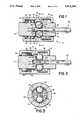
- FIG. 1is a vertical cross sectional view of the chuck assembly with a fitted shank portion from a tool bit;
- FIG. 2is a vertical cross sectional view of the chuck assembly showing actuation of the quick release feature and partial extraction of a tool bit from the chuck assembly;
- FIG. 3is a cross sectional view of the chuck assembly taken along section line 3--3 of FIG. 1;
- FIG. 4is a cross section of a profile for the locking shoulder of the chuck assembly
- FIG. 5is a cross section of a second profile for the locking shoulder of the chuck assembly
- FIG. 6is a cross section of a third profile for the locking shoulder.
- FIG. 7is a cross section of a fourth profile for the locking shoulder.
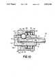
- FIG. 8is a vertical cross sectional view common to alternative embodiments of the chuck assembly of the present invention.
- FIG. 9Ais a cross sectional view of a first alternative embodiment of the chuck assembly, perpendicular to the longitudinal axis of a tool bit receiving bore.
- FIG. 9Bis a cross sectional view of a second alternative embodiment of the chuck assembly, perpendicular to the longitudinal axis of a tool bit receiving bore.
- FIG. 10is a cross sectional view of a third alternative embodiment of the chuck assembly, perpendicular to the longitudinal axis of a tool bit receiving bore.
- FIG. 1illustrates chuck assembly 10 of the present invention.
- Chuck assembly 10is shown mated with a tool bit 100 which is usable with a power tool or other device incorporating the chuck assembly.
- Chuck assembly 10includes a spindle 12 which provides connection to the power tool.
- Tool bit 100can be a drill, a driver for a fastener, or some other device.
- Tool bit 100includes a hexagonally shaped shank portion 102 for mating the tool bit to spindle 12
- Spindle 12terminates in a forward face 14.
- a forward opening 16is centered in forward face 14 for admitting tool bit 100 to shank receiving bore 18.
- Shank receiving bore 18is hexagonally shaped and extends rearward from front opening 16 into spindle 12 substantially aligned along the longitudinal axis of the spindle.
- Receiving bore 18terminates in spindle 12 along a rear terminating end 20 which is a face generally perpendicular to the longitudinal axis of the spindle.
- first and second radially extending bores 22 and 24communicate with bore 18.
- First and second radially extending bores 22 and 24extend from bore 18 through spindle 12 to an outer cylindrical surface 26 of the spindle.
- Detent balls 28 and 30are disposed in radially extending bores 22 and 24, respectively. Balls 28 and 30 are sized to fit loosely in the radially extending bores, permitting the balls to move axially within bores 22 and 24 respectively, and extend into bore 18 into contact with tool bit 100. Shoulders 29 and 31 disposed in bores 22 and 24 adjacent shaft 18 prevent detent balls 28 and 30 from passing completely into shaft 18.
- Detent balls 28 and 30are held in positions extending into bore 18 by a movable sleeve 32 disposed around outer cylindrical surface 26 when the movable sleeve 32 is in a maximum forward position.
- Movable sleeve 32is biased toward the forward end of spindle 12 by a compression spring 34.
- Compression spring 34is held in a rear bore 36 of movable sleeve 32 between the movable sleeve and spindle 12.
- Compression spring 34bears against a flange 35 mounted around outer cylindrical surface 26 and a radially inwardly extending locking shoulder 40 of movable sleeve 32.
- compression spring 34biases movable sleeve 32 forward bringing locking shoulder 40 into contact with detent balls 28 and 30, urging detent balls 28 and 30 forward into contact with retaining portions 42 and 44 of radial bores 22 and 24, respectively. In its forward biased position, locking shoulder 40 also holds detent balls 28 and 30 against tool bit 100 in bore 18.
- Locking shoulder 40can have any one of several profiles as discussed below.
- locking shoulder 40includes a rearward oriented face 46 which is generally perpendicular to the longitudinal axis of spindle 12 for providing a surface against which compression spring 34 can bear.
- a center bore portion 48Forward from and adjacent to rearward face 46 is a center bore portion 48 which is of a substantially minimum diameter allowing free movement of movable sleeve 32 over outer cylindrical surface 26 of spindle 12.
- Forward from center bore 48is an intermediate bore 50.
- a forward oriented face 52Between center bore 48 and intermediate bore 50 is a forward oriented face 52, which is substantially perpendicular to the longitudinal axis of spindle 12 and is adjacent both the center bore and the intermediate bore.
- Locking shoulder 40also includes a second forward oriented face 54 immediately forward intermediate bore 50 and adjacent a forward bore 56 of movable sleeve 32.
- Detent balls 28 and 30are locked against retaining portions 42 and 44 of radially extending bores 22 and 24 as locking shoulder 40 is urged forward into substantial alignment with bores 22 and 24 and into contact with the balls.
- Locking shoulder 40makes contact with detent balls 28 and 30 at two points on the balls allowing the locking shoulder to apply force to the detent balls in directions both normal and parallel to the longitudinal axis of spindle 12.
- the points of contactare along intermediate bore 50 and an intersection 58 between center bore 48 and forward oriented face 52. Both tangential and normal forces are applied to detent balls 28 and 30 at the contact point along intersection 52. Generally normal forces are applied to detent balls 28 and 30 at their contact points on intermediate bore 50. Balls 28 and 30 are also prevented from rotating by frictional forces tangential to the surface of the balls at the aforesaid contact points and at an additional contact point along retaining portions 42 and 44.
- Shank portion 102is a typically hexagonally shaped (although other noncircular profiles are known) end portion of a tool bit and is sized to fit snugly in receiving bore 18.
- Shank portion 102includes a circumferential groove 104 near shank end 106
- Circumferential groove 104includes three distinct surface profiles, including a radially inwardly extending rear radiused shoulder 108, a centered flat portion 110 and a radially inwardly extending forward radiused shoulder 112.
- Radially extending bores 22 and 24are spaced from rear terminating end 20 of receiving bore 18 to be substantially aligned with circumferential groove 104 when shank portion 102 is fully admitted to bore 20. At such time shank end 106 abuts rear terminating end 20. Forward or outward axial forces applied to tool bit 100 bring rear radiused shoulder 108 into contact with detent balls 28 and 30.
- the radius of radiused shoulder 108is substantially the same as the radius of detent balls 28 and 30, and, accordingly, detent balls 28 and 30 make contact along lines on the rear radiused shoulder running substantially the entire front to rear length of the shoulder.
- Detent balls 28 and 30are locked against rotation as described above and resist outward motion of tool bit 100 because of a force applied to the balls by retaining portions 42 and 44 opposite the extracting force. Detent balls 28 and 30 transmit the tool bit 100 opposite responsive axial force to the extracting force, thus preventing extraction of tool bit 100 from bore 18.
- FIG. 2illustrates extraction of tool bit 100 from receiving bore 18.
- Movable sleeve 32is translated rearward relative to spindle 12 retracting locking shoulder 40 from alignment with bores 22 and 24, thus freeing detent balls 28 and 30.
- Application of an extractive axial force to tool bit 100now results in outward radial displacement of detent balls 28 and 30 partially into forward bore 56 and out of receiving bore 18 as the detent balls ride up rear radiused shoulder 108, out of circumferential groove 104 and onto the rear part of shank 102.
- Tool bit 100is now easily removed from receiving bore 18 allowing replacement of the tool bit with another.
- FIG. 3is a cross sectional view of chuck assembly 10 taken along section line 3--3 of FIG. I.
- Detent balls 28 and 30are seen spaced slightly from center flat portion 110 along circumferential groove 104. The extension of detent balls 28 and 30 into bore 18 is easily seen. The alignment of bore 18 is indicated in phantom. Radially extending bores 22 and 24 are in opposing alignment along their respective longitudinal axes. Detent balls 28 and 30 are fixed in extension into bore 18 by contacting movable sleeve along center bore 50 of locking shoulder 40.
- FIGS. 4, 5, 6 and 7illustrate various profiles of locking shoulder 40.
- the profilesare characterized generally by a stepped conical shape which tapers along progressively smaller diameters from front to rear of movable sleeve 32.
- the profile of FIG. 4is the same as that depicted in FIGS. 1 and 2 above.
- the profile of FIG. 5is a variation of that in FIG. 4 with forward oriented face 52 replaced by a rearward conical taper 53 which provides the second contact surface for detent ball 28 along with intermediate bore 50.
- FIG. 6illustrates a locking shoulder 40 profile in which intermediate bore 50 has been replaced with first and second intermediate bores 60 and 62 providing stepwise progression toward larger and larger diameter bores from center bore 48 to forward bore 56.
- Forward oriented faces 64 and 66are positioned between center bore 48 and first intermediate bore 60, and first intermediate bore 60 and second intermediate bore 62, respectively.
- forward oriented faces 64 and 66have been replaced by rearward conical tapers 65 and 67.
- the various locking shoulder 40 profilesare easily machined variations in movable sleeve 32 allowing manufacture of modified movable sleeves for application in chuck assemblies where receiving bore profiles are smaller and where detent balls are of different radiuses.
- FIGS. 8, 9A and 9Billustrate alternative embodiments of the chuck assembly of the present invention.
- Chuck assembly 200can be manufactured with fewer or more detent balls than the pair of opposing detent balls 28 and 30 described above.
- a chuck assembly 200 with one detent ball 202would be cheaper to produce, but would not help center shank 102 in bore 18.
- the number of detent ballsis limited only by the size of the detent balls.
- FIG. 8illustrates detent ball 202 held against retaining portion 206 of bore 204 by locking shoulder 40 and an axially extractive force applied to tool bit 100.
- Detent balls 212 and 222 in bores 214 and 224, respectively,similarly retain tool bit 100 in hexagonal bore 18.
- the force vectors applied to tool bit 100 by detent balls 202, 212 and 224are radially balanced, centering tool bit 100 in bore 18. Where a single detent ball 202 is used (shown in FIG. 9B), the radial force vector is balanced against bore 18 with a loss of centering vectors provided by a plurality of detent balls.
- FIG. 10illustrates yet another embodiment of the invention, providing simplified construction.
- Chuck assembly 200is shown mated with a tool bit 100 which is usable with a power tool or other device incorporating the chuck assembly.
- Chuck assembly 200includes a spindle 111 which provides connection to the power tool.
- Tool bit 100can be a drill, a driver for a fastener, or some other device.
- Tool bit 100includes a hexagonally shaped shank portion 102 for mating the tool bit to spindle 111.
- Spindle 111terminates in a forward face 114.
- a forward opening 116is centered in forward face 114 for admitting tool bit 100 to shank receiving bore 118.
- Shank receiving bore 118is hexagonally shaped and extends rearward from forward opening 116 into spindle 111 substantially aligned along the longitudinal axis of the spindle.
- Receiving bore 118terminates within spindle 111 along a rear terminating end 120 which is a face generally perpendicular to the longitudinal axis of the spindle.
- a radially extending bore 122communicates from bore 118 to the exterior surface 126 of spindle 111.
- Detent ball 28is disposed in radially extending bore 122.
- Ball 28is sized to fit loosely in radially extending bore 122, permitting the ball to move axially within bore 122 and radially with respect to shank 102.
- ball 28When ball 28 is positioned to lock shank 102 in place it extends into bore 118 into contact with tool bit 100. Shoulder 129 disposed around the end of bore 122 adjacent bore 118 prevents detent ball 28 from passing completely into bore 118.
- Detent ball 28is held in position extending into bore 118 by a movable sleeve 132 disposed around outer cylindrical surface 126. This locking action occurs when movable sleeve 132 is in its maximum forward position. Movable sleeve 132 is biased toward the forward end of spindle 112 by a compression spring 34. Compression spring 34 is held in forward bore 156 of movable sleeve 132 between the movable sleeve and a flange 138 mounted around spindle 111. Compression spring 34 bears against flange 138 and a radially inward extending flange 180, which depends from movable sleeve 132.
- Locking shoulder 140can have any one of several profiles as discussed above. In FIG. 10, locking shoulder 140 is characterized by two steps of progressively narrower bores 150 and 148 rearward from forward bore 156. A forward oriented face 152, which is generally perpendicular to the longitudinal axis of spindle 111 is forward from and adjacent to rearward bore portion 148 which is of a substantially minimum diameter allowing free movement of movable sleeve 132 over outer cylindrical surface 126 of spindle 111. Locking shoulder 140 also includes a second forward oriented face 154 immediately forward intermediate bore 150 and adjacent a forward bore 156 of movable sleeve 132.
- Detent ball 28is locked against retaining portion 142 of radially extending bores 22 as locking shoulder 140 is urged forward into substantial alignment with bore 122 and into contact with ball 28.
- Locking shoulder 140makes contact with detent ball 28 at two points on the ball 28 allowing the locking shoulder to apply force to the detent ball 28 in directions both normal and parallel to the longitudinal axis of spindle 111.
- the points of contactare along intermediate bore 150 and an intersection 158 between rearward bore 148 and forward oriented face 152. Both tangential and normal forces are applied to detent ball 28 at the contact point along intersection 152. Generally normal forces are applied to detent ball 28 at its contact points on intermediate bore 150.
- Ball 28is also prevented from rotating by frictional forces tangential to the surface of the balls at the aforesaid contact points and at an additional contact point along retaining portions 142.
- Shank portion 102is a typically hexagonally shaped (although other noncircular profiles are known) end portion of a tool bit and is sized to fit snugly in receiving bore 118.
- Shank portion 102includes a circumferential groove 104 near shank end 106.
- Radially extending bore 122is spaced from rear terminating end 120 of receiving bore 118 to be substantially aligned with circumferential groove 104 when shank portion 102 is fully admitted to bore 118. At such time shank end 106 abuts rear terminating end 120. Forward or outward axial forces applied to tool bit 100 bring rear radiused shoulder 108 into contact with detent ball 28.
- the radius of radiused shoulder 108is substantially the same as the radius of detent ball 28, and, accordingly, detent ball 28 makes contact along lines on the rear radiused shoulder running substantially the entire front to rear length of the shoulder.
- Detent ball 28is locked against rotation as described above and resist outward motion of tool bit 100 because of a force applied to the balls by retaining portion 142 opposite the extracting force. Detent ball 28 transmits to the tool bit 100 opposite responsive axial force to the extracting force, thus preventing extraction of tool bit 100 from bore 118.
- the present inventionprovides a quick change chuck assembly of both great simplicity of manufacture and high reliability in service. Simplicity in manufacture is aided by the lack of required close tolerances in the spindle and in the movable sleeve.
- the chuck assembly of the present inventionis highly resistant to accidental removal of tool bits due to extractive axial forces applied to tool bits in normal work conditions.
- the inventionnonetheless allows highly reliable quick change of tool bits. Removal is accomplished by applying simultaneous opposite forces to the movable sleeve and to a tool bit to extract the tool bit from the spindle.
Landscapes
- Engineering & Computer Science (AREA)
- Mechanical Engineering (AREA)
- Gripping On Spindles (AREA)
Abstract
Description
This is a, continuation in part of patent application Ser. No. 07/241,710 filed Sept. 8, 1988 and now U.S. Pat. No. 4,900,202. su
1. Field of The Invention.
The invention relates to chuck assemblies for tool bits and, more particularly, to a quick release chuck adapted to prevent undesired axial extraction of a tool bit such as a drill from the chuck assembly.
2. Description of the Prior Art.
Tool bits include tools used for drilling, driving fastener devices such as screws, nuts and bolts, and other work elements requiring rotational motion. The American National Standards Institute has a specification for such tools known as ANSI B107.4-1982 which refers to driving and spindle ends for portable powered and hand held machines using the tool bits. Tool bits in accordance with the standard have a hexagonally configured shank with a circumferential groove formed into the shank. The circumferential groove has a flat, bottom portion disposed between two radiused shoulder portions. The standard reflects the long term and pervasive use of such tool bits and the large inventory of tools available.
It has long been recognized that the ability to quickly change tool bits in the spindle of a power source is an advantageous feature. Numerous examples exist in the art of quick release tool chucks. An example of one such quick release chuck apparatus is that described in U.S. Pat. No. 4,692,073. The quick release chuck disclosed therein includes a spring biased sleeve disposed on a spindle having an inclined cam surface disposed against a single ball.
The ball in turn applies normal and tangential forces against a groove in the shank of the tool bit to hold the tool bit in a bore. The sleeve is urged into contact with the ball by a compression spring disposed between the spindle and the sleeve. A ring secured to the spindle limits the movement of the sleeve in one direction, and the compression spring and the spindle limit the movement of the sleeve in the opposite direction.
U.S. Pat. No. 4,692,073 addresses objectionable end play caused by the presence of the flat, bottomed portion of the circumferential groove in the tool bits. However, construction of devices taught by the patent require maintenance of extremely tight manufacturing standards with respect to the radius of the ball and both the radius of the radial bore it travels in and the radius of the radiused shoulders in the groove which it abuts against. The ramped sleeve which is used to apply normal and tangential forces to the ball can allow the ball to be forced out of the retaining position by a large outward axial force applied to the tool. A large outward axial force can occur, for example, where the tool bit is a drill bit being removed from a freshly drilled bore. Use of a single detent ball can also result in a nonconcentric orientation of the tool.
A chuck assembly for a tool bit includes a spindle with a quick release mechanism adapted to prevent undesired axial extraction of the tool bit from the spindle. The tool bit includes a shank portion with a circumferential groove in accordance with the ANSI standard. A longitudinally extending bore is provided in the spindle for receiving the shank portion of the tool bit. Opposing radial bores communicate with the shank receiving bore. Detent balls are disposed in the opposing radial bores. The shank is retained in the bore by the balls, which extend from the radial bores into the shank receiving bore and against the circumferential groove.
The detent balls disposition around the shank in opposing positions help center the shank. A spring biased shoulder is urged against the balls locking them against a retaining face. Attempted axial extraction of the tool bit from the bore, without release of the detent balls, pulls the balls against a retaining face producing an opposite tangential force to the axial retraction force. The responsive tangential force prevents extraction of the tool bit from the shank receiving bore.
FIG. 1 is a vertical cross sectional view of the chuck assembly with a fitted shank portion from a tool bit;
FIG. 2 is a vertical cross sectional view of the chuck assembly showing actuation of the quick release feature and partial extraction of a tool bit from the chuck assembly;
FIG. 3 is a cross sectional view of the chuck assembly taken alongsection line 3--3 of FIG. 1;
FIG. 4 is a cross section of a profile for the locking shoulder of the chuck assembly;
FIG. 5 is a cross section of a second profile for the locking shoulder of the chuck assembly;
FIG. 6 is a cross section of a third profile for the locking shoulder; and
FIG. 7 is a cross section of a fourth profile for the locking shoulder.
FIG. 8 is a vertical cross sectional view common to alternative embodiments of the chuck assembly of the present invention.
FIG. 9A is a cross sectional view of a first alternative embodiment of the chuck assembly, perpendicular to the longitudinal axis of a tool bit receiving bore.
FIG. 9B is a cross sectional view of a second alternative embodiment of the chuck assembly, perpendicular to the longitudinal axis of a tool bit receiving bore.
FIG. 10 is a cross sectional view of a third alternative embodiment of the chuck assembly, perpendicular to the longitudinal axis of a tool bit receiving bore.
FIG. 1 illustrateschuck assembly 10 of the present invention. Chuckassembly 10 is shown mated with atool bit 100 which is usable with a power tool or other device incorporating the chuck assembly. Chuckassembly 10 includes aspindle 12 which provides connection to the power tool.Tool bit 100 can be a drill, a driver for a fastener, or some other device.Tool bit 100 includes a hexagonallyshaped shank portion 102 for mating the tool bit to spindle 12
Spindle 12 terminates in aforward face 14. Aforward opening 16 is centered inforward face 14 for admittingtool bit 100 to shank receivingbore 18. Shank receivingbore 18 is hexagonally shaped and extends rearward from front opening 16 intospindle 12 substantially aligned along the longitudinal axis of the spindle. Receiving bore 18 terminates inspindle 12 along arear terminating end 20 which is a face generally perpendicular to the longitudinal axis of the spindle.
Opposed first and second radially extendingbores bore 18. First and second radially extendingbores bore 18 throughspindle 12 to an outercylindrical surface 26 of the spindle.Detent balls bores Balls bores bore 18 into contact withtool bit 100.Shoulders bores adjacent shaft 18 preventdetent balls shaft 18.
Rearward movement ofmovable sleeve 32 along the longitudinal axis ofspindle 12compresses compression spring 34 betweenflange 38 and lockingshoulder 40.Compression spring 34 biasesmovable sleeve 32 forward bringing lockingshoulder 40 into contact withdetent balls detent balls portions shoulder 40 also holdsdetent balls tool bit 100 inbore 18.
Lockingshoulder 40 can have any one of several profiles as discussed below. In FIG. 1, lockingshoulder 40 includes a rearward orientedface 46 which is generally perpendicular to the longitudinal axis ofspindle 12 for providing a surface against whichcompression spring 34 can bear. Forward from and adjacent to rearward face 46 is acenter bore portion 48 which is of a substantially minimum diameter allowing free movement ofmovable sleeve 32 over outercylindrical surface 26 ofspindle 12. Forward from center bore 48 is anintermediate bore 50. Between center bore 48 andintermediate bore 50 is a forward orientedface 52, which is substantially perpendicular to the longitudinal axis ofspindle 12 and is adjacent both the center bore and the intermediate bore. Lockingshoulder 40 also includes a second forward orientedface 54 immediately forwardintermediate bore 50 and adjacent a forward bore 56 ofmovable sleeve 32.
Locking of the positions ofdetent balls tool bit 100 disposed in hexagonal receiving bore 18.Shank portion 102 is a typically hexagonally shaped (although other noncircular profiles are known) end portion of a tool bit and is sized to fit snugly in receivingbore 18.Shank portion 102 includes acircumferential groove 104 nearshank end 106Circumferential groove 104 includes three distinct surface profiles, including a radially inwardly extending rearradiused shoulder 108, a centeredflat portion 110 and a radially inwardly extending forwardradiused shoulder 112.
FIG. 2 illustrates extraction oftool bit 100 from receivingbore 18.Movable sleeve 32 is translated rearward relative to spindle 12retracting locking shoulder 40 from alignment withbores detent balls tool bit 100 now results in outward radial displacement ofdetent balls bore 18 as the detent balls ride up rearradiused shoulder 108, out ofcircumferential groove 104 and onto the rear part ofshank 102.Tool bit 100 is now easily removed from receivingbore 18 allowing replacement of the tool bit with another.
FIG. 3 is a cross sectional view ofchuck assembly 10 taken alongsection line 3--3 of FIG.I. Detent balls flat portion 110 alongcircumferential groove 104. The extension ofdetent balls bore 18 is easily seen. The alignment ofbore 18 is indicated in phantom.Radially extending bores Detent balls bore 18 by contacting movable sleeve along center bore 50 of lockingshoulder 40.
FIGS. 4, 5, 6 and 7 illustrate various profiles of lockingshoulder 40. The profiles are characterized generally by a stepped conical shape which tapers along progressively smaller diameters from front to rear ofmovable sleeve 32. The profile of FIG. 4 is the same as that depicted in FIGS. 1 and 2 above. The profile of FIG. 5 is a variation of that in FIG. 4 with forward orientedface 52 replaced by a rearwardconical taper 53 which provides the second contact surface fordetent ball 28 along withintermediate bore 50.
FIG. 6 illustrates a lockingshoulder 40 profile in which intermediate bore 50 has been replaced with first and secondintermediate bores intermediate bore 60, and firstintermediate bore 60 and secondintermediate bore 62, respectively. In FIG. 7, forward oriented faces 64 and 66 have been replaced by rearwardconical tapers
The various lockingshoulder 40 profiles are easily machined variations inmovable sleeve 32 allowing manufacture of modified movable sleeves for application in chuck assemblies where receiving bore profiles are smaller and where detent balls are of different radiuses.
FIGS. 8, 9A and 9B illustrate alternative embodiments of the chuck assembly of the present invention. Like numbers refer to like structures between figures.Chuck assembly 200 can be manufactured with fewer or more detent balls than the pair of opposingdetent balls chuck assembly 200 with onedetent ball 202 would be cheaper to produce, but would not help centershank 102 inbore 18. Achuck assembly 200 withdetent balls shank 102 inhexagonal bore 18. In theory, the number of detent balls is limited only by the size of the detent balls.
FIG. 8 illustratesdetent ball 202 held against retainingportion 206 ofbore 204 by lockingshoulder 40 and an axially extractive force applied totool bit 100.Detent balls bores tool bit 100 inhexagonal bore 18. The force vectors applied totool bit 100 bydetent balls tool bit 100 inbore 18. Where asingle detent ball 202 is used (shown in FIG. 9B), the radial force vector is balanced againstbore 18 with a loss of centering vectors provided by a plurality of detent balls.
FIG. 10 illustrates yet another embodiment of the invention, providing simplified construction.Chuck assembly 200 is shown mated with atool bit 100 which is usable with a power tool or other device incorporating the chuck assembly.Chuck assembly 200 includes a spindle 111 which provides connection to the power tool.Tool bit 100 can be a drill, a driver for a fastener, or some other device.Tool bit 100 includes a hexagonally shapedshank portion 102 for mating the tool bit to spindle 111.
Spindle 111 terminates in aforward face 114. Aforward opening 116 is centered inforward face 114 for admittingtool bit 100 toshank receiving bore 118.Shank receiving bore 118 is hexagonally shaped and extends rearward from forward opening 116 into spindle 111 substantially aligned along the longitudinal axis of the spindle. Receivingbore 118 terminates within spindle 111 along arear terminating end 120 which is a face generally perpendicular to the longitudinal axis of the spindle.
Aradially extending bore 122 communicates frombore 118 to theexterior surface 126 of spindle 111.Detent ball 28 is disposed in radially extendingbore 122.Ball 28 is sized to fit loosely in radially extendingbore 122, permitting the ball to move axially withinbore 122 and radially with respect toshank 102. Whenball 28 is positioned to lockshank 102 in place it extends intobore 118 into contact withtool bit 100.Shoulder 129 disposed around the end ofbore 122adjacent bore 118 preventsdetent ball 28 from passing completely intobore 118.
Rearward movement ofmovable sleeve 132 along the longitudinal axis of spindle 111 compressescompression spring 34 betweenflange 138 and inward extendingflange 180. Compression spring 134 biasesmovable sleeve 132 in the direction offorward face 114. If permitted, lockingshoulder 140 comes into contact withdetent ball 28 urging the detent ball forward into contact with retainingportion 142 ofradial bore 122. In this forward position, lockingshoulder 140 also holdsdetent ball 28 againsttool bit 100 inbore 118.
Lockingshoulder 140 can have any one of several profiles as discussed above. In FIG. 10, lockingshoulder 140 is characterized by two steps of progressivelynarrower bores forward bore 156. A forward orientedface 152, which is generally perpendicular to the longitudinal axis of spindle 111 is forward from and adjacent to rearward boreportion 148 which is of a substantially minimum diameter allowing free movement ofmovable sleeve 132 over outercylindrical surface 126 of spindle 111. Lockingshoulder 140 also includes a second forward orientedface 154 immediately forwardintermediate bore 150 and adjacent aforward bore 156 ofmovable sleeve 132.
Locking of the position ofdetent ball 28 retains and fixes the position oftool bit 100 disposed in hexagonal receiving bore 118.Shank portion 102 is a typically hexagonally shaped (although other noncircular profiles are known) end portion of a tool bit and is sized to fit snugly in receivingbore 118.Shank portion 102 includes acircumferential groove 104 nearshank end 106.
In summary, the present invention provides a quick change chuck assembly of both great simplicity of manufacture and high reliability in service. Simplicity in manufacture is aided by the lack of required close tolerances in the spindle and in the movable sleeve. The chuck assembly of the present invention is highly resistant to accidental removal of tool bits due to extractive axial forces applied to tool bits in normal work conditions.
The invention nonetheless allows highly reliable quick change of tool bits. Removal is accomplished by applying simultaneous opposite forces to the movable sleeve and to a tool bit to extract the tool bit from the spindle.
Although the present invention has been described with reference to preferred embodiments, workers skilled in the art will recognize that changes may be made in form and detail without departing from the spirit and scope of the invention.
Claims (12)
1. A quick release chuck assembly for a tool bit having a shank and a groove extending circumferentially about the shank with a radiused portion, the chuck assembly comprising:
a spindle including,
a forward face,
a longitudinal bore into the spindle from the forward face having an inner end for receiving the shank of the tool bit,
at least a first radial bore communicating with the longitudinal bore through the spindle, and
a detent ball disposed in each radial bore and extendable into the longitudinal bore against the groove of the shank of the tool bit;
a sleeve disposed around the spindle including,
a forward bore disposed around the spindle for receiving the detent balls when the balls are moved out of the longitudinal bore,
a radially inwardly extending shoulder adjacent the forward bore for engaging and urging the balls into the longitudinal bore and against the groove of the shank,
the shoulder further including a substantially minimum diameter center bore permitting free translation of the sleeve around the spindle and a concentrically graduated portion between the forward bore and the center bore, and
the concentrically graduated portion further including a first intermediate bore between the center bore and the forward bore which is larger in diameter than the center bore and smaller in diameter than the forward bore; and
a spring means for biasing the sleeve against the detent balls causing the shoulder to contact the balls to urge the detent balls forward against the interior walls of the radial bores generating responsive tangential forces through the detent balls against the radiused portion of the groove and further to urge the detent balls into the longitudinal bore and against the shank whereby the detent balls are positionally locked between the shoulder, the shank and the radial bores;
whereby the shank of the tool bit is locked in position with substantially no end play between the detent balls and the inner end of the longitudinal bore.
2. The chuck assembly of claim 1 wherein the concentrically graduated portion includes a second intermediate bore between the first intermediate bore and the forward bore which is larger in diameter than the first intermediate bore and smaller in diameter than the forward bore.
3. The chuck assembly of claim 1 wherein the concentrically graduated portion includes a first forward oriented face perpendicular to the longitudinal axis of the longitudinal bore adjacent the first intermediate bore and the center bore and a second forward oriented face perpendicular to the longitudinal axis of the non-circular bore adjacent the first intermediate and the forward bore.
4. The chuck assembly of claim 2 wherein the concentrically graduated portion includes a first forward oriented face perpendicular to the longitudinal axis of the longitudinal bore adjacent the first intermediate bore and the center bore, a second forward oriented face perpendicular to the longitudinal axis of the longitudinal bore and adjacent the first intermediate bore and the second intermediate bore, and a third intermediate face perpendicular to the longitudinal axis of the longitudinal bore and adjacent the second intermediate bore and the forward bore.
5. The chuck assembly of claim 1 wherein the concentrically graduated portion includes a first rearward oriented conical taper adjacent the first intermediate bore and the center bore and a first forward oriented face perpendicular to the longitudinal axis of the longitudinal bore adjacent the first intermediate and the forward bore.
6. The chuck assembly of claim 2 wherein the concentrically graduated portion includes a first rearward oriented conical taper adjacent the first intermediate bore and the center bore and a second rearward oriented conical taper adjacent the first intermediate bore and the second intermediate bore and a first forward oriented face perpendicular to the longitudinal axis of the longitudinal bore adjacent the second intermediate bore and the forward bore.
7. A quick release chuck assembly for a tool bit having a shank and a groove extending circumferentially about the shank with a radiused portion, the chuck assembly comprising:
spindle means including,
a longitudinal bore having an inner end for receiving the shank of the tool bit,
at least a first radial bore communicating with the longitudinal bore, and
a ball disposed in each radial bore and extendible into the longitudinal bore and against the groove of the shank of a tool bit inserted into the longitudinal bore;
sleeve means disposed around the spindle means including,
a forward bore disposed around the spindle means for receiving the balls when the balls are moved out of the longitudinal bore, and
radially inwardly extending shoulder means adjacent the forward bore for engaging and urging the balls into the longitudinal bore and against the groove of the shank,
the shoulder means including a substantially minimum diameter center bore permitting free translation of the sleeve means around the spindle means and a concentrically graduated portion between the forward bore and the center bore,
the concentrically graduated portion including a first intermediate bore between the center bore and the forward bore which is larger in diameter than the center bore and smaller in diameter than the forward bore; and
spring means for biasing the sleeve means against the balls whereby the shoulder means contact the balls to apply normal forces against the groove of the shank and tangential forces against the radiused portion of the groove resisting outward axial forces applied to the tool bit.
8. The chuck assembly of claim 7 wherein the concentrically graduated portion includes a second intermediate bore between the first intermediate bore and the forward bore which is larger in diameter than the first intermediate bore and smaller in diameter than the forward bore.
9. The chuck assembly of claim 7 wherein the concentrically graduated portion includes a first forward oriented face perpendicular to the longitudinal axis of the longitudinal bore adjacent the first intermediate bore and the center bore and a second forward oriented face perpendicular to the longitudinal axis of the longitudinal bore adjacent the first intermediate and the forward bore.
10. The chuck assembly of claim 8 wherein the concentrically graduated portion includes a first forward oriented face perpendicular to the longitudinal axis of the longitudinal bore adjacent the first intermediate bore and the center bore, a second forward oriented face perpendicular to the longitudinal axis of the longitudinal bore and adjacent the first intermediate bore and the second intermediate bore, and a third intermediate face perpendicular to the longitudinal axis of the longitudinal bore and adjacent the second intermediate bore and the forward bore.
11. The chuck assembly of claim 7 wherein the concentrically graduated portion includes a first rearward oriented conical taper adjacent the first intermediate bore and the center bore and a first forward oriented face perpendicular to the longitudinal axis of the longitudinal bore adjacent the first intermediate and the forward bore.
12. The chuck assembly of claim 8 wherein the concentrically graduated portion includes a first rearward oriented conical taper adjacent the first intermediate bore and the center bore and a second rearward oriented conical taper adjacent the first intermediate bore and the second intermediate bore and a first forward oriented face perpendicular to the longitudinal axis of the longitudinal bore adjacent the second intermediate bore and the forward bore.
Priority Applications (1)
| Application Number | Priority Date | Filing Date | Title |
|---|---|---|---|
| US07/475,653US5013194A (en) | 1988-09-08 | 1990-02-06 | Chuck assembly for tool bits |
Applications Claiming Priority (2)
| Application Number | Priority Date | Filing Date | Title |
|---|---|---|---|
| US07/241,710US4900202A (en) | 1988-09-08 | 1988-09-08 | Chuck assembly for tool bits |
| US07/475,653US5013194A (en) | 1988-09-08 | 1990-02-06 | Chuck assembly for tool bits |
Related Parent Applications (1)
| Application Number | Title | Priority Date | Filing Date |
|---|---|---|---|
| US07/241,710ContinuationUS4900202A (en) | 1988-09-08 | 1988-09-08 | Chuck assembly for tool bits |
Publications (1)
| Publication Number | Publication Date |
|---|---|
| US5013194Atrue US5013194A (en) | 1991-05-07 |
Family
ID=26934514
Family Applications (1)
| Application Number | Title | Priority Date | Filing Date |
|---|---|---|---|
| US07/475,653Expired - LifetimeUS5013194A (en) | 1988-09-08 | 1990-02-06 | Chuck assembly for tool bits |
Country Status (1)
| Country | Link |
|---|---|
| US (1) | US5013194A (en) |
Cited By (133)
| Publication number | Priority date | Publication date | Assignee | Title |
|---|---|---|---|---|
| US5236433A (en)* | 1991-05-08 | 1993-08-17 | Othy, Inc. | Tool driver |
| US5398946A (en)* | 1993-12-29 | 1995-03-21 | Poly-Tech Industries | Chuck having one-step lock and release |
| US5417527A (en)* | 1994-08-12 | 1995-05-23 | Wienhold; James L. | Quick change chuck assembly for tool bits |
| US5464229A (en)* | 1994-05-26 | 1995-11-07 | Power Tool Holders, Inc. | Quick release chuck device |
| US5466100A (en)* | 1994-10-24 | 1995-11-14 | Alfa Manufacturing Industries, Inc. | Multi-stepped power drill bit having handle chuck adaptor |
| US5499986A (en)* | 1994-01-07 | 1996-03-19 | Smith & Nephew Richards Inc. | Quick release handle apparatus for removing and inserting intramedullary nails |
| US5573255A (en)* | 1995-05-05 | 1996-11-12 | Power Tool Holders, Inc. | Quick release chuck device for saw blades |
| EP0742082A1 (en)* | 1995-05-04 | 1996-11-13 | HILTI Aktiengesellschaft | Device for torque transmission for hand tools |
| US5577743A (en)* | 1995-05-10 | 1996-11-26 | Power Tool Holders, Inc. | Quick release chuck device |
| USD380069S (en)* | 1995-10-23 | 1997-06-17 | Waxing Corporation Of America, Inc. | Detailing polisher |
| US5664634A (en)* | 1995-10-23 | 1997-09-09 | Waxing Corporation Of America, Inc. | Power tool |
| US5678961A (en)* | 1995-05-11 | 1997-10-21 | Fleege; Dennis W. | Quick change adapter |
| US5729904A (en)* | 1995-11-01 | 1998-03-24 | Linvatec Corporation | Wrenchless collect for surgical blade |
| US5775981A (en)* | 1997-03-12 | 1998-07-07 | Yang; Maw-Chyuan | Air die grinder |
| US5807040A (en)* | 1995-10-09 | 1998-09-15 | Hilti Aktiengesellschaft | Tool bit chuck |
| US5817096A (en)* | 1996-11-25 | 1998-10-06 | Othy, Inc. | Tool driver |
| US5921562A (en)* | 1998-01-27 | 1999-07-13 | Robison; Troy | Magnetic chuck assembly |
| US5975815A (en)* | 1995-12-09 | 1999-11-02 | Eva Maria Zierpka | Drilling tool |
| US6007268A (en)* | 1998-04-24 | 1999-12-28 | Specialized Marketing International, Inc. | Radial and axial locking release collar |
| US6135462A (en)* | 1999-05-24 | 2000-10-24 | Gary Sebastian | Snap-in chuck |
| US6156016A (en)* | 1998-01-06 | 2000-12-05 | Maginot Vascular Systems | Catheter systems and associated methods utilizing removable inner catheter or catheters |
| US6190371B1 (en) | 1999-01-15 | 2001-02-20 | Maginot Vascular Systems | Catheter system having retractable working catheter and associated method |
| US6199872B1 (en) | 1999-08-13 | 2001-03-13 | Maxtech Consumer Products, L.L.C. | Quick-release mechanism for screwdriver bits and the like |
| US6260857B1 (en) | 1999-01-06 | 2001-07-17 | James L. Wienhold | Quick-change three-jaw drill chuck |
| US6270085B1 (en) | 1999-10-01 | 2001-08-07 | Tsai-Ching Chen | Chuck device for tool bits |
| WO2001058631A1 (en)* | 2000-02-13 | 2001-08-16 | W.P.W. Engineering Ltd. | Countersinking tool for fast-exchange chucks |
| US6290606B1 (en)* | 1997-09-19 | 2001-09-18 | The Charles Machines Works, Inc. | Polygonal ball drive system for earth auger |
| US6302408B1 (en) | 1997-05-10 | 2001-10-16 | Eva-Maria Zierpka | Tool system that can be coupled to a lathe drive shaft |
| US6325393B1 (en) | 1999-10-01 | 2001-12-04 | Tsai-Ching Chen | Chuck device for tools |
| WO2001066287A3 (en)* | 2000-03-09 | 2002-02-07 | Black & Decker Inc | Rotary tool holder |
| US6347914B1 (en)* | 2000-03-09 | 2002-02-19 | Black & Decker Inc. | Rotary tool holder |
| US20020091362A1 (en)* | 1998-01-06 | 2002-07-11 | Maginot Thomas J. | Medical procedure using catheter system having removability feature |
| US6457916B2 (en) | 1999-11-15 | 2002-10-01 | Insty-Bit, Inc. | Locking quick-change chuck assembly |
| US6475207B1 (en) | 1999-01-15 | 2002-11-05 | Maginot Catheter Technologies, Inc. | Retractable catheter systems and associated methods |
| US6488452B1 (en) | 1999-08-12 | 2002-12-03 | Vermont American Corporation | Drill and drive apparatus having arrangement to accommodate long drill bits |
| US6497418B2 (en)* | 2000-02-10 | 2002-12-24 | Hitachi Koki Co., Ltd. | Tool-bit holding device in percussion tool |
| WO2003015991A1 (en)* | 2001-07-26 | 2003-02-27 | Zierpka Guenter | Rotating machine, approximately in the form of a hand drill, a percussion drill, a drill hammer or a battery screwdriver |
| US6533291B2 (en) | 2001-02-14 | 2003-03-18 | Power Tool Holders Incorporated | Chuck having quick change mechanism |
| US20030075880A1 (en)* | 2001-10-24 | 2003-04-24 | Girardeau Samuel G. | Chuck having quick change mechanism |
| US6561523B1 (en) | 1999-11-18 | 2003-05-13 | James L. Wienhold | Automatic tool-bit holder |
| US6585705B1 (en) | 1999-01-15 | 2003-07-01 | Maginot Catheter Technologies, Inc. | Retractable catheter systems |
| US6588994B2 (en) | 2000-05-17 | 2003-07-08 | James L. Wienhold | Drill bit tail |
| US6616149B1 (en) | 2002-03-19 | 2003-09-09 | S-B Power Tool Corporation | Quick-release chuck having compact collar |
| US20030189299A1 (en)* | 2000-05-12 | 2003-10-09 | Huggins Mark S. | Chuck with quick change |
| WO2003103518A1 (en) | 2002-06-07 | 2003-12-18 | Medtronic, Inc D/B/A Medtronic Midas Rex | Surgical instrument with rotary cutting member and quick release coupling arrangement |
| US20030230862A1 (en)* | 2002-06-18 | 2003-12-18 | Peters Michael P. | Bit holder |
| US20040021276A1 (en)* | 2002-08-02 | 2004-02-05 | Allan Scott W. | Quick-connect chuck mechanism |
| US6722667B2 (en)* | 2000-06-09 | 2004-04-20 | Jore Corporation | Workpiece connector for a power tool |
| US20040074349A1 (en)* | 2002-10-16 | 2004-04-22 | Mou-Tang Liou | Tool including a tool bit and a handle |
| US6743218B2 (en) | 1999-01-15 | 2004-06-01 | Cathlogic, Inc. | Retractable catheter systems and associated methods |
| US20040118176A1 (en)* | 2002-12-20 | 2004-06-24 | Avk Industrial Products, A Division Of Sps Technologies Inc. | Quick release/eject drive assembly |
| US6755423B2 (en)* | 2002-07-17 | 2004-06-29 | Li Jiun Chiu | Tool coupling device for changeable tool members |
| US6761361B2 (en) | 2002-08-09 | 2004-07-13 | Credo Technology Corporation | Drill and drive apparatus with improved tool holder |
| US6786685B2 (en) | 2002-07-19 | 2004-09-07 | Toolovation, Llc | Power tool having a quick-release chuck assembly |
| US20040173061A1 (en)* | 2002-10-16 | 2004-09-09 | Mou-Tang Liou | Tool including bit and handle |
| US20040250766A1 (en)* | 2003-04-30 | 2004-12-16 | Tokyo Electron Limited | Hybrid ball-lock attachment apparatus |
| US6843484B2 (en) | 2002-07-08 | 2005-01-18 | Monte L. Schroeder | Quick change chuck |
| US20050045002A1 (en)* | 2003-08-29 | 2005-03-03 | Cluthe Gary Paul | Multiple bit hand tool with automatic bit locking |
| US20050059925A1 (en)* | 1999-01-15 | 2005-03-17 | Maginot Thomas J. | Catheter systems and associated methods |
| US20050096609A1 (en)* | 1999-01-15 | 2005-05-05 | Maginot Thomas J. | Methods of performing medical procedures with catheter systems having movable member |
| US6966562B1 (en) | 2001-05-31 | 2005-11-22 | Wienhold James L | Multiple mode chuck |
| US7008412B2 (en) | 1998-01-06 | 2006-03-07 | Cathlogic, Inc. | Subcutaneous port catheter system and associated method |
| US20060053974A1 (en)* | 2003-03-15 | 2006-03-16 | Aesculap Ag & Co. Kg | Coupling for a surgical rotary drive hand piece |
| US20060163824A1 (en)* | 2005-01-24 | 2006-07-27 | Makita Corporation | Power tool |
| US20060191379A1 (en)* | 2005-02-25 | 2006-08-31 | Irwin Industrial Tool Company | Fastener extractor |
| US7175184B1 (en) | 2003-10-24 | 2007-02-13 | Pilling Weck Incorporated | Collect tool holder and method of making same |
| WO2006061789A3 (en)* | 2004-12-08 | 2007-07-12 | Invent Inc | Multi ball self-adjusting self-centering tool holder (mbssth) and multi ball self-adjusting self-centering clamping system (mbsscs) |
| US20070157472A1 (en)* | 2006-01-11 | 2007-07-12 | Cooper Brands, Inc. | Utility knife with releasable blade retention mechanism |
| US20070277656A1 (en)* | 2006-03-02 | 2007-12-06 | Zeiler Jeffrey M | Cutting tool |
| DE10249199B4 (en)* | 2002-03-22 | 2007-12-06 | Chen, Tsai-Ching, Fu Hsing | Feeding device for miniature tool bits |
| USD568474S1 (en) | 2006-10-19 | 2008-05-06 | Westport Medical, Inc. | Bit for a powered surgical instrument |
| US20080111323A1 (en)* | 2006-11-09 | 2008-05-15 | Westport Medical, Inc. | Bit holders |
| USD575808S1 (en) | 2007-03-02 | 2008-08-26 | Milwaukee Electric Tool Corporation | Cutting tool |
| US20080246233A1 (en)* | 2004-03-15 | 2008-10-09 | Wienhold James L | Dual Size Tool-Bit Holder |
| US20090007846A1 (en)* | 2004-09-20 | 2009-01-08 | Ernst Keller | Diffuser gravity support |
| US20090033042A1 (en)* | 2006-08-08 | 2009-02-05 | Rinner James A | Tool Chuck |
| US20090060644A1 (en)* | 2007-08-31 | 2009-03-05 | Strategic Ideas, Llc | Fastener and Assembly Utilizing the Same |
| US20090087273A1 (en)* | 2006-03-02 | 2009-04-02 | Douglas Allen | Cutting tool |
| US20090101380A1 (en)* | 2006-05-09 | 2009-04-23 | Atlas Copco Tools Ab | Portable Power Tool with Double Freewheel Drive Shaft Lock |
| US20090126960A1 (en)* | 2006-05-09 | 2009-05-21 | Atlas Copco Tools Ab | Portable Power Tool with Drive Shaft Lock Means |
| US20090290931A1 (en)* | 2007-08-31 | 2009-11-26 | Strategic Ideas, Llc | Fastener and Assembly Utilizing the Same |
| USD605672S1 (en) | 2007-03-01 | 2009-12-08 | Milwaukee Electric Tool Corporation | Cutting blade |
| US20090308629A1 (en)* | 2005-05-31 | 2009-12-17 | Yukiwa Seiko Kabushiki Kaisha | Rotating tool |
| US20100145016A1 (en)* | 2008-09-11 | 2010-06-10 | Calretex, Llc | Compositions and methods for purifying calreticulin |
| US20100219593A1 (en)* | 2009-02-27 | 2010-09-02 | Black & Decker Inc. | Bit Retention Device |
| US20100225073A1 (en)* | 2006-11-09 | 2010-09-09 | Douglas Roy Porter | Bit holders |
| US20100282485A1 (en)* | 2009-05-05 | 2010-11-11 | Black & Decker Inc. | Power tool with integrated bit retention device |
| WO2011104105A1 (en)* | 2010-02-25 | 2011-09-01 | Robert Bosch Gmbh | Handheld machine tool |
| DE202011050549U1 (en) | 2011-06-24 | 2011-11-02 | Yih Cheng Factory Co., Ltd. | chuck |
| US20120006879A1 (en)* | 2010-07-12 | 2012-01-12 | Chervon (Hk) Limited | Electric hammer |
| US20120326401A1 (en)* | 2009-02-27 | 2012-12-27 | Black & Decker Inc. | Bit Retention Device |
| TWI410307B (en)* | 2012-09-04 | 2013-10-01 | Tien I Ind Co Ltd | Holding sleeve and rod tool including the same, and fabrication methods thereof |
| WO2013167496A1 (en) | 2012-05-08 | 2013-11-14 | Aesculap Ag | Quick-action coupling |
| US9156147B2 (en) | 2012-02-15 | 2015-10-13 | Black & Decker Inc. | Quick change bit holder with ring magnet |
| US20150313612A1 (en)* | 2014-04-30 | 2015-11-05 | Gyrus Acmi, Inc., D.B.A. Olympus Surgical Technologies America | Rotary tool with improved coupling assembly |
| US9227309B2 (en) | 2012-02-15 | 2016-01-05 | Black & Decker Inc. | Quick change bit holder with ring magnet |
| EP2962658A1 (en)* | 2014-07-04 | 2016-01-06 | Mecanumeric | Digitally controlled machine for, in particular, the production of dental crowns and other dental prostheses |
| US9500038B2 (en) | 2013-02-01 | 2016-11-22 | Milwaukee Electric Tool Corporation | Auger bit with replaceable cutting bit |
| US9505108B2 (en) | 2012-02-15 | 2016-11-29 | Black & Decker Inc. | Bit holder with floating magnet sleeve |
| USD780548S1 (en) | 2015-07-22 | 2017-03-07 | Ac (Macao Commercial Offshore) Limited | Power tool |
| US20170143440A1 (en)* | 2015-10-27 | 2017-05-25 | Mcginley Engineered Solutions, Llc | Techniques and instruments for placement of orthopedic implants relative to bone features |
| USD789761S1 (en) | 2015-11-02 | 2017-06-20 | Black & Decker Inc. | Torsion bit |
| US9707626B2 (en)* | 2014-10-22 | 2017-07-18 | Rote Mate Industry Co., Ltd. | Hole saw assembly |
| KR20170093134A (en)* | 2014-11-05 | 2017-08-14 | 주니어. 토마스 에스. 존스톤 | Detachable actuator arm for distraction devices |
| US9784295B2 (en) | 2007-08-31 | 2017-10-10 | The Blanchard Patent Holding Company, Llc | Fastener and assembly utilizing the same |
| USD806493S1 (en) | 2015-07-22 | 2018-01-02 | Tti (Macao Commercial Offshore) Limited | Tool adapter |
| US9873155B1 (en) | 2009-04-22 | 2018-01-23 | Insty-Bit, Llc | Quick change tool bit holder for round shafts |
| US20180055519A1 (en)* | 2016-08-31 | 2018-03-01 | Medtronic Ps Medical, Inc. | Multiple Connection Drive Shaft |
| US9943946B2 (en) | 2012-02-15 | 2018-04-17 | Black & Decker Inc. | Tool bits with floating magnet sleeves |
| WO2018075935A1 (en)* | 2016-10-21 | 2018-04-26 | Mako Surgical Corp. | Systems and tools for use with surgical robotic manipulators |
| TWI627030B (en)* | 2017-07-05 | 2018-06-21 | 徐銘隆 | Hand Tool And Holding Sleeve Thereof |
| US10150205B2 (en) | 2012-02-15 | 2018-12-11 | Black & Decker Inc. | Fastening tools with floating magnet sleeves |
| US20190054602A1 (en)* | 2017-08-15 | 2019-02-21 | Honda Motor Co., Ltd. | Fastener holder tool and method |
| GB2568215A (en)* | 2017-05-15 | 2019-05-15 | Zethon Ltd | Coupling mechanism for a surgical device |
| US10307896B2 (en)* | 2016-12-30 | 2019-06-04 | Zu-Shung Shu | Sleeve device for receiving bits |
| US10321920B2 (en) | 2015-11-06 | 2019-06-18 | Mcginley Engineered Solutions, Llc | Measurement system for use with surgical burr instrument |
| US10321921B2 (en) | 2015-10-27 | 2019-06-18 | Mcginley Engineered Solutions, Llc | Unicortical path detection for a surgical depth measurement system |
| US10349952B2 (en) | 2013-11-08 | 2019-07-16 | Mcginley Engineered Solutions, Llc | Surgical saw with sensing technology for determining cut through of bone and depth of the saw blade during surgery |
| US10398453B2 (en) | 2013-09-04 | 2019-09-03 | Mcginley Engineered Solutions, Llc | Drill bit penetration measurement systems and methods |
| US10758250B2 (en) | 2014-09-05 | 2020-09-01 | Mcginley Engineered Solutions, Llc | Instrument leading edge measurement system and method |
| US10806525B2 (en) | 2017-10-02 | 2020-10-20 | Mcginley Engineered Solutions, Llc | Surgical instrument with real time navigation assistance |
| US10987113B2 (en) | 2017-08-25 | 2021-04-27 | Mcginley Engineered Solutions, Llc | Sensing of surgical instrument placement relative to anatomic structures |
| US11065744B2 (en) | 2018-07-20 | 2021-07-20 | Milwaukee Electric Tool Corporation | Tool bit holder |
| US20210291338A1 (en)* | 2020-03-23 | 2021-09-23 | Milwaukee Electric Tool Corporation | Rotary hammer |
| US20210362315A1 (en)* | 2019-09-23 | 2021-11-25 | Tien-I Industrial Co., Ltd. | Impact tool head |
| US11247254B2 (en) | 2019-02-26 | 2022-02-15 | Steven Hopf | Adjustable dent removal tool |
| US11253330B2 (en) | 2018-09-26 | 2022-02-22 | Mako Surgical Corp. | Systems and tools for use with surgical robotic manipulators |
| US11332828B2 (en)* | 2019-10-04 | 2022-05-17 | Applied Materials, Inc. | Gas distribution assembly mounting for fragile plates to prevent breakage |
| US11370103B2 (en)* | 2014-01-17 | 2022-06-28 | Thunderchuck Innovations Inc. | Bit driving tool and device for use therewith |
| US11529180B2 (en) | 2019-08-16 | 2022-12-20 | Mcginley Engineered Solutions, Llc | Reversible pin driver |
| US11685032B2 (en) | 2020-07-02 | 2023-06-27 | Milwaukee Electric Tool Corporation | Rotary impact tool having bit holding device |
| US11833563B2 (en) | 2019-02-26 | 2023-12-05 | Steven Hopf | Adjustable dent removal tool |
| US12256945B2 (en) | 2015-08-31 | 2025-03-25 | Medtronic Ps Medical, Inc. | Surgical burs |
Citations (23)
| Publication number | Priority date | Publication date | Assignee | Title |
|---|---|---|---|---|
| US81260A (en)* | 1868-08-18 | davis | ||
| US1602708A (en)* | 1924-11-05 | 1926-10-12 | George W Russell | Chuck |
| US2350565A (en)* | 1942-08-12 | 1944-06-06 | Cons Vultee Aircraft Corp | Drill chuck |
| US2370487A (en)* | 1943-03-22 | 1945-02-27 | Curtiss Wright Corp | Quick-change drill chuck |
| US2736562A (en)* | 1953-10-27 | 1956-02-28 | Howard D Blackburn | Interchangeable drill |
| US2767992A (en)* | 1954-08-23 | 1956-10-23 | Agnes G Emrick | Chuck devices for taps |
| US2807473A (en)* | 1956-02-20 | 1957-09-24 | Alfred J Kiehne | Tool mountings and release |
| US2926020A (en)* | 1958-01-02 | 1960-02-23 | Pacific Tool And Mfg Co | Quick-change chuck |
| US2987334A (en)* | 1959-06-22 | 1961-06-06 | Apex Machine & Tool Company | Tool holders |
| US3255792A (en)* | 1964-03-18 | 1966-06-14 | Josef E Louis | Locking device for tool handles |
| US3367727A (en)* | 1965-10-22 | 1968-02-06 | Abraham W. Ward | Oral surgery tool with interchangeable blades |
| US3583715A (en)* | 1967-09-15 | 1971-06-08 | Eric Jahrl | Quick change chuck |
| US3672692A (en)* | 1970-05-18 | 1972-06-27 | Bilz Otto Werkzeug | Quick-change chucks |
| US3945653A (en)* | 1973-10-30 | 1976-03-23 | Robert Bosch Gmbh | Holder for tools and similar objects |
| US4209182A (en)* | 1978-10-05 | 1980-06-24 | Cooper Industries, Inc. | Bit retainer for screwdriver |
| US4290617A (en)* | 1979-06-11 | 1981-09-22 | The Boeing Company | Motor quick-change chuck system for tool having cylindrically shaped adapter portion wherein relative longitudinal movement between chuck and tool being driven is eliminated |
| US4434859A (en)* | 1981-06-29 | 1984-03-06 | Hilti Aktiengesellschaft | Hammer drill for performing rotary drilling or percussive drilling |
| USRE31755E (en)* | 1975-11-14 | 1984-12-04 | Robert Bosch Gmbh | Tool and chuck for hammer drill |
| US4577875A (en)* | 1982-10-29 | 1986-03-25 | Miyakawa Industry Co., Ltd. | Exchange chuck for a tool |
| US4588335A (en)* | 1984-09-14 | 1986-05-13 | Pearson Jr Claude C | Quick change tool retention device for power operated mechanism |
| US4594036A (en)* | 1983-05-20 | 1986-06-10 | Kenneth R. Muzzy | Quick change tool chuck system |
| US4692073A (en)* | 1985-02-25 | 1987-09-08 | Martindell J Richard | Handle adapter and chuck apparatus for power bits |
| US4900202A (en)* | 1988-09-08 | 1990-02-13 | Wienhold James L | Chuck assembly for tool bits |
- 1990
- 1990-02-06USUS07/475,653patent/US5013194A/ennot_activeExpired - Lifetime
Patent Citations (23)
| Publication number | Priority date | Publication date | Assignee | Title |
|---|---|---|---|---|
| US81260A (en)* | 1868-08-18 | davis | ||
| US1602708A (en)* | 1924-11-05 | 1926-10-12 | George W Russell | Chuck |
| US2350565A (en)* | 1942-08-12 | 1944-06-06 | Cons Vultee Aircraft Corp | Drill chuck |
| US2370487A (en)* | 1943-03-22 | 1945-02-27 | Curtiss Wright Corp | Quick-change drill chuck |
| US2736562A (en)* | 1953-10-27 | 1956-02-28 | Howard D Blackburn | Interchangeable drill |
| US2767992A (en)* | 1954-08-23 | 1956-10-23 | Agnes G Emrick | Chuck devices for taps |
| US2807473A (en)* | 1956-02-20 | 1957-09-24 | Alfred J Kiehne | Tool mountings and release |
| US2926020A (en)* | 1958-01-02 | 1960-02-23 | Pacific Tool And Mfg Co | Quick-change chuck |
| US2987334A (en)* | 1959-06-22 | 1961-06-06 | Apex Machine & Tool Company | Tool holders |
| US3255792A (en)* | 1964-03-18 | 1966-06-14 | Josef E Louis | Locking device for tool handles |
| US3367727A (en)* | 1965-10-22 | 1968-02-06 | Abraham W. Ward | Oral surgery tool with interchangeable blades |
| US3583715A (en)* | 1967-09-15 | 1971-06-08 | Eric Jahrl | Quick change chuck |
| US3672692A (en)* | 1970-05-18 | 1972-06-27 | Bilz Otto Werkzeug | Quick-change chucks |
| US3945653A (en)* | 1973-10-30 | 1976-03-23 | Robert Bosch Gmbh | Holder for tools and similar objects |
| USRE31755E (en)* | 1975-11-14 | 1984-12-04 | Robert Bosch Gmbh | Tool and chuck for hammer drill |
| US4209182A (en)* | 1978-10-05 | 1980-06-24 | Cooper Industries, Inc. | Bit retainer for screwdriver |
| US4290617A (en)* | 1979-06-11 | 1981-09-22 | The Boeing Company | Motor quick-change chuck system for tool having cylindrically shaped adapter portion wherein relative longitudinal movement between chuck and tool being driven is eliminated |
| US4434859A (en)* | 1981-06-29 | 1984-03-06 | Hilti Aktiengesellschaft | Hammer drill for performing rotary drilling or percussive drilling |
| US4577875A (en)* | 1982-10-29 | 1986-03-25 | Miyakawa Industry Co., Ltd. | Exchange chuck for a tool |
| US4594036A (en)* | 1983-05-20 | 1986-06-10 | Kenneth R. Muzzy | Quick change tool chuck system |
| US4588335A (en)* | 1984-09-14 | 1986-05-13 | Pearson Jr Claude C | Quick change tool retention device for power operated mechanism |
| US4692073A (en)* | 1985-02-25 | 1987-09-08 | Martindell J Richard | Handle adapter and chuck apparatus for power bits |
| US4900202A (en)* | 1988-09-08 | 1990-02-13 | Wienhold James L | Chuck assembly for tool bits |
Cited By (217)
| Publication number | Priority date | Publication date | Assignee | Title |
|---|---|---|---|---|
| US5236433A (en)* | 1991-05-08 | 1993-08-17 | Othy, Inc. | Tool driver |
| US5398946A (en)* | 1993-12-29 | 1995-03-21 | Poly-Tech Industries | Chuck having one-step lock and release |
| US5499986A (en)* | 1994-01-07 | 1996-03-19 | Smith & Nephew Richards Inc. | Quick release handle apparatus for removing and inserting intramedullary nails |
| US5464229A (en)* | 1994-05-26 | 1995-11-07 | Power Tool Holders, Inc. | Quick release chuck device |
| WO1996005010A1 (en)* | 1994-08-12 | 1996-02-22 | Wienhold, James, L. | Quick change chuck assembly for tool bits |
| US5417527A (en)* | 1994-08-12 | 1995-05-23 | Wienhold; James L. | Quick change chuck assembly for tool bits |
| US5466100A (en)* | 1994-10-24 | 1995-11-14 | Alfa Manufacturing Industries, Inc. | Multi-stepped power drill bit having handle chuck adaptor |
| EP0742082A1 (en)* | 1995-05-04 | 1996-11-13 | HILTI Aktiengesellschaft | Device for torque transmission for hand tools |
| US5704744A (en)* | 1995-05-04 | 1998-01-06 | Hilti Aktiengeschaft | Arrangement for transmitting torque in a manually operated tool |
| US5573255A (en)* | 1995-05-05 | 1996-11-12 | Power Tool Holders, Inc. | Quick release chuck device for saw blades |
| US5577743A (en)* | 1995-05-10 | 1996-11-26 | Power Tool Holders, Inc. | Quick release chuck device |
| US5678961A (en)* | 1995-05-11 | 1997-10-21 | Fleege; Dennis W. | Quick change adapter |
| US5807040A (en)* | 1995-10-09 | 1998-09-15 | Hilti Aktiengesellschaft | Tool bit chuck |
| USD380069S (en)* | 1995-10-23 | 1997-06-17 | Waxing Corporation Of America, Inc. | Detailing polisher |
| US5664634A (en)* | 1995-10-23 | 1997-09-09 | Waxing Corporation Of America, Inc. | Power tool |
| US5839196A (en)* | 1995-11-01 | 1998-11-24 | Linvatec Corporation | Wrenchless collet for surgical blade |
| US5729904A (en)* | 1995-11-01 | 1998-03-24 | Linvatec Corporation | Wrenchless collect for surgical blade |
| US5975815A (en)* | 1995-12-09 | 1999-11-02 | Eva Maria Zierpka | Drilling tool |
| US5817096A (en)* | 1996-11-25 | 1998-10-06 | Othy, Inc. | Tool driver |
| US5775981A (en)* | 1997-03-12 | 1998-07-07 | Yang; Maw-Chyuan | Air die grinder |
| US6302408B1 (en) | 1997-05-10 | 2001-10-16 | Eva-Maria Zierpka | Tool system that can be coupled to a lathe drive shaft |
| US6290606B1 (en)* | 1997-09-19 | 2001-09-18 | The Charles Machines Works, Inc. | Polygonal ball drive system for earth auger |
| US7008412B2 (en) | 1998-01-06 | 2006-03-07 | Cathlogic, Inc. | Subcutaneous port catheter system and associated method |
| US20020091362A1 (en)* | 1998-01-06 | 2002-07-11 | Maginot Thomas J. | Medical procedure using catheter system having removability feature |
| US6156016A (en)* | 1998-01-06 | 2000-12-05 | Maginot Vascular Systems | Catheter systems and associated methods utilizing removable inner catheter or catheters |
| US5921562A (en)* | 1998-01-27 | 1999-07-13 | Robison; Troy | Magnetic chuck assembly |
| US6007268A (en)* | 1998-04-24 | 1999-12-28 | Specialized Marketing International, Inc. | Radial and axial locking release collar |
| US6260857B1 (en) | 1999-01-06 | 2001-07-17 | James L. Wienhold | Quick-change three-jaw drill chuck |
| US20050059925A1 (en)* | 1999-01-15 | 2005-03-17 | Maginot Thomas J. | Catheter systems and associated methods |
| US6743218B2 (en) | 1999-01-15 | 2004-06-01 | Cathlogic, Inc. | Retractable catheter systems and associated methods |
| US6723084B1 (en) | 1999-01-15 | 2004-04-20 | Maginot Catheter Technologies, Inc. | Catheter systems having multilumen guide catheter and retractable working catheter positioned in at least one lumen thereof |
| US20050096609A1 (en)* | 1999-01-15 | 2005-05-05 | Maginot Thomas J. | Methods of performing medical procedures with catheter systems having movable member |
| US6190371B1 (en) | 1999-01-15 | 2001-02-20 | Maginot Vascular Systems | Catheter system having retractable working catheter and associated method |
| US6585705B1 (en) | 1999-01-15 | 2003-07-01 | Maginot Catheter Technologies, Inc. | Retractable catheter systems |
| US6475207B1 (en) | 1999-01-15 | 2002-11-05 | Maginot Catheter Technologies, Inc. | Retractable catheter systems and associated methods |
| US6135462A (en)* | 1999-05-24 | 2000-10-24 | Gary Sebastian | Snap-in chuck |
| US6488452B1 (en) | 1999-08-12 | 2002-12-03 | Vermont American Corporation | Drill and drive apparatus having arrangement to accommodate long drill bits |
| US6199872B1 (en) | 1999-08-13 | 2001-03-13 | Maxtech Consumer Products, L.L.C. | Quick-release mechanism for screwdriver bits and the like |
| US6270085B1 (en) | 1999-10-01 | 2001-08-07 | Tsai-Ching Chen | Chuck device for tool bits |
| US6325393B1 (en) | 1999-10-01 | 2001-12-04 | Tsai-Ching Chen | Chuck device for tools |
| US6457916B2 (en) | 1999-11-15 | 2002-10-01 | Insty-Bit, Inc. | Locking quick-change chuck assembly |
| US6561523B1 (en) | 1999-11-18 | 2003-05-13 | James L. Wienhold | Automatic tool-bit holder |
| US6497418B2 (en)* | 2000-02-10 | 2002-12-24 | Hitachi Koki Co., Ltd. | Tool-bit holding device in percussion tool |
| WO2001058631A1 (en)* | 2000-02-13 | 2001-08-16 | W.P.W. Engineering Ltd. | Countersinking tool for fast-exchange chucks |
| US6347914B1 (en)* | 2000-03-09 | 2002-02-19 | Black & Decker Inc. | Rotary tool holder |
| WO2001066287A3 (en)* | 2000-03-09 | 2002-02-07 | Black & Decker Inc | Rotary tool holder |
| US7040630B2 (en)* | 2000-05-12 | 2006-05-09 | Jacobs Chuck Manufacturing Company | Chuck with quick change |
| US20030189299A1 (en)* | 2000-05-12 | 2003-10-09 | Huggins Mark S. | Chuck with quick change |
| US20060175769A1 (en)* | 2000-05-12 | 2006-08-10 | Jacobs Chuck Manufacturing Company | Chuck with quick change |
| US7160065B2 (en) | 2000-05-12 | 2007-01-09 | Jacobs Chuck Manufacturing Company | Chuck with quick change |
| US6688610B2 (en) | 2000-05-12 | 2004-02-10 | Power Tool Holders Incorporated | Chuck with quick change |
| US6588994B2 (en) | 2000-05-17 | 2003-07-08 | James L. Wienhold | Drill bit tail |
| US6935637B2 (en) | 2000-06-09 | 2005-08-30 | Jore Corporation | Workpiece connector for a power tool |
| US6722667B2 (en)* | 2000-06-09 | 2004-04-20 | Jore Corporation | Workpiece connector for a power tool |
| US20040262856A1 (en)* | 2000-06-09 | 2004-12-30 | Jore Corporation | Workpiece connector for a power tool |
| US20040094908A1 (en)* | 2000-06-09 | 2004-05-20 | Jore Corporation | Workpiece connector for a power tool |
| US6533291B2 (en) | 2001-02-14 | 2003-03-18 | Power Tool Holders Incorporated | Chuck having quick change mechanism |
| US6722668B2 (en) | 2001-02-14 | 2004-04-20 | Power Tool Holders Incorporated | Chuck having quick change mechanism |
| US6966562B1 (en) | 2001-05-31 | 2005-11-22 | Wienhold James L | Multiple mode chuck |
| US6988734B2 (en) | 2001-07-26 | 2006-01-24 | Zierpka Guenter | Rotating machine, approximately in the form of a hand drill, a percussion drill, a drill hammer or a battery screwdriver |
| US20040013485A1 (en)* | 2001-07-26 | 2004-01-22 | Gunter Zierpka | Rotating machine, approximately in the form of a hand drill, a percussion drill, a drill hammer or a battery screwdriver |
| WO2003015991A1 (en)* | 2001-07-26 | 2003-02-27 | Zierpka Guenter | Rotating machine, approximately in the form of a hand drill, a percussion drill, a drill hammer or a battery screwdriver |
| US6834864B2 (en) | 2001-10-24 | 2004-12-28 | Power Tool Holders Incorporated | Chuck having quick change mechanism |
| US20030075880A1 (en)* | 2001-10-24 | 2003-04-24 | Girardeau Samuel G. | Chuck having quick change mechanism |
| US6616149B1 (en) | 2002-03-19 | 2003-09-09 | S-B Power Tool Corporation | Quick-release chuck having compact collar |
| DE10249199B4 (en)* | 2002-03-22 | 2007-12-06 | Chen, Tsai-Ching, Fu Hsing | Feeding device for miniature tool bits |
| EP1549231A4 (en)* | 2002-06-07 | 2010-04-14 | Medtronic Inc | Surgical instrument with rotary cutting member and quick release coupling arrangement |
| EP2502583A1 (en)* | 2002-06-07 | 2012-09-26 | Medtronic, Inc. | Surgical instrument with rotary cutting member and quick release coupling arrangement |
| WO2003103518A1 (en) | 2002-06-07 | 2003-12-18 | Medtronic, Inc D/B/A Medtronic Midas Rex | Surgical instrument with rotary cutting member and quick release coupling arrangement |
| US6929266B2 (en) | 2002-06-18 | 2005-08-16 | Black & Decker Inc. | Bit holder |
| US20030230862A1 (en)* | 2002-06-18 | 2003-12-18 | Peters Michael P. | Bit holder |
| US6843484B2 (en) | 2002-07-08 | 2005-01-18 | Monte L. Schroeder | Quick change chuck |
| US6755423B2 (en)* | 2002-07-17 | 2004-06-29 | Li Jiun Chiu | Tool coupling device for changeable tool members |
| US6786685B2 (en) | 2002-07-19 | 2004-09-07 | Toolovation, Llc | Power tool having a quick-release chuck assembly |
| US7278640B2 (en) | 2002-08-02 | 2007-10-09 | Maxtech Manufacturing Inc. | Quick-connect chuck mechanism |
| US20040021276A1 (en)* | 2002-08-02 | 2004-02-05 | Allan Scott W. | Quick-connect chuck mechanism |
| US6761361B2 (en) | 2002-08-09 | 2004-07-13 | Credo Technology Corporation | Drill and drive apparatus with improved tool holder |
| US20040074349A1 (en)* | 2002-10-16 | 2004-04-22 | Mou-Tang Liou | Tool including a tool bit and a handle |
| US7036404B2 (en)* | 2002-10-16 | 2006-05-02 | Mou-Tang Liou | Tool including bit and handle |
| US20040173061A1 (en)* | 2002-10-16 | 2004-09-09 | Mou-Tang Liou | Tool including bit and handle |
| US6725749B1 (en)* | 2002-10-16 | 2004-04-27 | Mou-Tang Liou | Tool including a tool bit and a handle |
| US6840075B2 (en) | 2002-12-20 | 2005-01-11 | Avk Industrial Products, Division Of Sps Technologies, Inc. | Quick release/eject drive assembly |
| US20040118176A1 (en)* | 2002-12-20 | 2004-06-24 | Avk Industrial Products, A Division Of Sps Technologies Inc. | Quick release/eject drive assembly |
| US20060053974A1 (en)* | 2003-03-15 | 2006-03-16 | Aesculap Ag & Co. Kg | Coupling for a surgical rotary drive hand piece |
| US20040250766A1 (en)* | 2003-04-30 | 2004-12-16 | Tokyo Electron Limited | Hybrid ball-lock attachment apparatus |
| US7296534B2 (en)* | 2003-04-30 | 2007-11-20 | Tokyo Electron Limited | Hybrid ball-lock attachment apparatus |
| US7156005B2 (en)* | 2003-08-29 | 2007-01-02 | Duron Plastics Limited | Multiple bit hand tool with automatic bit locking |
| US20050045002A1 (en)* | 2003-08-29 | 2005-03-03 | Cluthe Gary Paul | Multiple bit hand tool with automatic bit locking |
| US7175184B1 (en) | 2003-10-24 | 2007-02-13 | Pilling Weck Incorporated | Collect tool holder and method of making same |
| US8844940B2 (en) | 2004-03-15 | 2014-09-30 | Insty-Bit, Llc | Dual Size tool-bit holder |
| US8292304B2 (en) | 2004-03-15 | 2012-10-23 | Insty-Bit, Llc | Dual size tool-bit holder |
| US20110140376A1 (en)* | 2004-03-15 | 2011-06-16 | Wienhold James L | Dual Size Tool-Bit Holder |
| US7896355B2 (en) | 2004-03-15 | 2011-03-01 | Wienhold James L | Dual size tool-bit holder |
| US20080246233A1 (en)* | 2004-03-15 | 2008-10-09 | Wienhold James L | Dual Size Tool-Bit Holder |
| US8075690B2 (en)* | 2004-09-20 | 2011-12-13 | Applied Materials, Inc. | Diffuser gravity support |
| US20090007846A1 (en)* | 2004-09-20 | 2009-01-08 | Ernst Keller | Diffuser gravity support |
| WO2006061789A3 (en)* | 2004-12-08 | 2007-07-12 | Invent Inc | Multi ball self-adjusting self-centering tool holder (mbssth) and multi ball self-adjusting self-centering clamping system (mbsscs) |
| US20060163824A1 (en)* | 2005-01-24 | 2006-07-27 | Makita Corporation | Power tool |
| US7654779B2 (en)* | 2005-01-24 | 2010-02-02 | Makita Corporation | Power tool |
| US20060191379A1 (en)* | 2005-02-25 | 2006-08-31 | Irwin Industrial Tool Company | Fastener extractor |
| US7152509B2 (en) | 2005-02-25 | 2006-12-26 | Irwin Industrial Tool Company | Fastener extractor |
| US20090308629A1 (en)* | 2005-05-31 | 2009-12-17 | Yukiwa Seiko Kabushiki Kaisha | Rotating tool |
| US7845428B2 (en)* | 2005-05-31 | 2010-12-07 | Yukiwa Seiko Kabushiki Kaisha | Rotating tool |
| US20070157472A1 (en)* | 2006-01-11 | 2007-07-12 | Cooper Brands, Inc. | Utility knife with releasable blade retention mechanism |
| US7661911B2 (en) | 2006-03-02 | 2010-02-16 | Milwaukee Electric Tool Corporation | Cutting tool |
| US9339874B2 (en) | 2006-03-02 | 2016-05-17 | Milwaukee Electric Tool Corporation | Cutting tool |
| US8328477B2 (en) | 2006-03-02 | 2012-12-11 | Milwaukee Electric Tool Corporation | Cutting tool |
| US20090087273A1 (en)* | 2006-03-02 | 2009-04-02 | Douglas Allen | Cutting tool |
| US20070277656A1 (en)* | 2006-03-02 | 2007-12-06 | Zeiler Jeffrey M | Cutting tool |
| US8371777B2 (en) | 2006-03-02 | 2013-02-12 | Milwaukee Electric Tool Corporation | Cutting tool |
| US7625160B2 (en) | 2006-03-02 | 2009-12-01 | Milwaukee Electric Tool Corporation | Cutting tool |
| US20100322733A1 (en)* | 2006-03-02 | 2010-12-23 | Douglas Allen | Cutting tool |
| US20070280798A1 (en)* | 2006-03-02 | 2007-12-06 | Zeiler Jeffrey M | Cutting tool |
| US10618119B2 (en) | 2006-03-02 | 2020-04-14 | Milwaukee Electric Tool Corporation | Cutting tool |
| US20090101380A1 (en)* | 2006-05-09 | 2009-04-23 | Atlas Copco Tools Ab | Portable Power Tool with Double Freewheel Drive Shaft Lock |
| US20090126960A1 (en)* | 2006-05-09 | 2009-05-21 | Atlas Copco Tools Ab | Portable Power Tool with Drive Shaft Lock Means |
| US20090033042A1 (en)* | 2006-08-08 | 2009-02-05 | Rinner James A | Tool Chuck |
| USD568474S1 (en) | 2006-10-19 | 2008-05-06 | Westport Medical, Inc. | Bit for a powered surgical instrument |
| US8882113B2 (en) | 2006-11-09 | 2014-11-11 | Westport Medical, Inc. | Bit holders |
| US20080111323A1 (en)* | 2006-11-09 | 2008-05-15 | Westport Medical, Inc. | Bit holders |
| US20100225073A1 (en)* | 2006-11-09 | 2010-09-09 | Douglas Roy Porter | Bit holders |
| USD605672S1 (en) | 2007-03-01 | 2009-12-08 | Milwaukee Electric Tool Corporation | Cutting blade |
| USD575808S1 (en) | 2007-03-02 | 2008-08-26 | Milwaukee Electric Tool Corporation | Cutting tool |
| US9784295B2 (en) | 2007-08-31 | 2017-10-10 | The Blanchard Patent Holding Company, Llc | Fastener and assembly utilizing the same |
| US20090290931A1 (en)* | 2007-08-31 | 2009-11-26 | Strategic Ideas, Llc | Fastener and Assembly Utilizing the Same |
| US8251606B2 (en) | 2007-08-31 | 2012-08-28 | The Blanchard Patent Holding Company, Llc | Fastener and assembly utilizing the same |
| US7762739B2 (en) | 2007-08-31 | 2010-07-27 | Strategic Ideas, Llc | Fastener and assembly utilizing the same |
| US20090060644A1 (en)* | 2007-08-31 | 2009-03-05 | Strategic Ideas, Llc | Fastener and Assembly Utilizing the Same |
| US8529151B2 (en) | 2007-08-31 | 2013-09-10 | The Blanchard Patent Holding Company, Llc | Fastener and assembly utilizing the same |
| US20100145016A1 (en)* | 2008-09-11 | 2010-06-10 | Calretex, Llc | Compositions and methods for purifying calreticulin |
| US8800999B2 (en)* | 2009-02-27 | 2014-08-12 | Black & Decker Inc. | Bit retention device |
| US20140312578A1 (en)* | 2009-02-27 | 2014-10-23 | Black & Decker Inc. | Bit retention device |
| US20120326401A1 (en)* | 2009-02-27 | 2012-12-27 | Black & Decker Inc. | Bit Retention Device |
| US8622401B2 (en) | 2009-02-27 | 2014-01-07 | Black & Decker Inc. | Bit retention device |
| US20100219593A1 (en)* | 2009-02-27 | 2010-09-02 | Black & Decker Inc. | Bit Retention Device |
| US9067266B2 (en)* | 2009-02-27 | 2015-06-30 | Black & Decker Inc. | Bit retention device |
| US9873155B1 (en) | 2009-04-22 | 2018-01-23 | Insty-Bit, Llc | Quick change tool bit holder for round shafts |
| US20100282485A1 (en)* | 2009-05-05 | 2010-11-11 | Black & Decker Inc. | Power tool with integrated bit retention device |
| US8381830B2 (en) | 2009-05-05 | 2013-02-26 | Black & Decker Inc. | Power tool with integrated bit retention device |
| WO2011104105A1 (en)* | 2010-02-25 | 2011-09-01 | Robert Bosch Gmbh | Handheld machine tool |
| CN102762327A (en)* | 2010-02-25 | 2012-10-31 | 罗伯特·博世有限公司 | Handheld machine tool |
| CN102762327B (en)* | 2010-02-25 | 2016-07-06 | 罗伯特·博世有限公司 | Hand held power machine |
| US20120006879A1 (en)* | 2010-07-12 | 2012-01-12 | Chervon (Hk) Limited | Electric hammer |
| US8893945B2 (en)* | 2010-07-12 | 2014-11-25 | Chervon (Hk) Limited | Electric hammer |
| DE202011050549U1 (en) | 2011-06-24 | 2011-11-02 | Yih Cheng Factory Co., Ltd. | chuck |
| US10556329B2 (en) | 2012-02-15 | 2020-02-11 | Black & Decker Inc. | Tool bits with floating magnet sleeves |
| US10040179B2 (en) | 2012-02-15 | 2018-08-07 | Black & Decker Inc. | Fastener tool assemblies |
| US9227309B2 (en) | 2012-02-15 | 2016-01-05 | Black & Decker Inc. | Quick change bit holder with ring magnet |
| US10150205B2 (en) | 2012-02-15 | 2018-12-11 | Black & Decker Inc. | Fastening tools with floating magnet sleeves |
| US9156147B2 (en) | 2012-02-15 | 2015-10-13 | Black & Decker Inc. | Quick change bit holder with ring magnet |
| US9943946B2 (en) | 2012-02-15 | 2018-04-17 | Black & Decker Inc. | Tool bits with floating magnet sleeves |
| US9505108B2 (en) | 2012-02-15 | 2016-11-29 | Black & Decker Inc. | Bit holder with floating magnet sleeve |
| DE102012207651A1 (en) | 2012-05-08 | 2013-11-14 | Aesculap Ag | Quick-coupling |
| WO2013167496A1 (en) | 2012-05-08 | 2013-11-14 | Aesculap Ag | Quick-action coupling |
| US9629640B2 (en) | 2012-05-08 | 2017-04-25 | Aesculap Ag | Quick-action coupling |
| TWI410307B (en)* | 2012-09-04 | 2013-10-01 | Tien I Ind Co Ltd | Holding sleeve and rod tool including the same, and fabrication methods thereof |
| US9500038B2 (en) | 2013-02-01 | 2016-11-22 | Milwaukee Electric Tool Corporation | Auger bit with replaceable cutting bit |
| US11058436B2 (en) | 2013-09-04 | 2021-07-13 | Mcginley Engineered Solutions, Llc | Drill bit penetration measurement system and methods |
| US10398453B2 (en) | 2013-09-04 | 2019-09-03 | Mcginley Engineered Solutions, Llc | Drill bit penetration measurement systems and methods |
| US12232745B2 (en) | 2013-11-08 | 2025-02-25 | Mcginley Engineered Solutions, Llc | Surgical saw with sensing technology for determining cut through of bone and depth of the saw blade during surgery |
| US11284906B2 (en) | 2013-11-08 | 2022-03-29 | Mcginley Engineered Solutions, Llc | Surgical saw with sensing technology for determining cut through of bone and depth of the saw blade during surgery |
| US10349952B2 (en) | 2013-11-08 | 2019-07-16 | Mcginley Engineered Solutions, Llc | Surgical saw with sensing technology for determining cut through of bone and depth of the saw blade during surgery |
| US11370103B2 (en)* | 2014-01-17 | 2022-06-28 | Thunderchuck Innovations Inc. | Bit driving tool and device for use therewith |
| US9504478B2 (en)* | 2014-04-30 | 2016-11-29 | Gyrus ACMI , Inc. | Rotary tool with improved coupling assembly |
| US9414848B2 (en) | 2014-04-30 | 2016-08-16 | Gyrus Acmi, Inc. | Rotary tool with improved coupling assembly |
| US20150313612A1 (en)* | 2014-04-30 | 2015-11-05 | Gyrus Acmi, Inc., D.B.A. Olympus Surgical Technologies America | Rotary tool with improved coupling assembly |
| US10278712B2 (en) | 2014-04-30 | 2019-05-07 | Gyrus Acmi, Inc. | Rotary tool with improved coupling assembly |
| FR3023198A1 (en)* | 2014-07-04 | 2016-01-08 | Mecanumeric | DIGITAL CONTROL MACHINE FOR, IN PARTICULAR, THE PRODUCTION OF DENTAL CROWNS AND OTHER DENTAL PROSTHESES. |
| EP2962658A1 (en)* | 2014-07-04 | 2016-01-06 | Mecanumeric | Digitally controlled machine for, in particular, the production of dental crowns and other dental prostheses |
| US11517331B2 (en) | 2014-09-05 | 2022-12-06 | Mcginley Engineered Solutions, Llc | Instrument leading edge measurement system and method |
| US10758250B2 (en) | 2014-09-05 | 2020-09-01 | Mcginley Engineered Solutions, Llc | Instrument leading edge measurement system and method |
| US9707626B2 (en)* | 2014-10-22 | 2017-07-18 | Rote Mate Industry Co., Ltd. | Hole saw assembly |
| KR20170093134A (en)* | 2014-11-05 | 2017-08-14 | 주니어. 토마스 에스. 존스톤 | Detachable actuator arm for distraction devices |
| KR102190569B1 (en) | 2014-11-05 | 2020-12-15 | 주니어. 토마스 에스. 존스톤 | Detachable actuator arm for distraction devices |
| USD806493S1 (en) | 2015-07-22 | 2018-01-02 | Tti (Macao Commercial Offshore) Limited | Tool adapter |
| USD780548S1 (en) | 2015-07-22 | 2017-03-07 | Ac (Macao Commercial Offshore) Limited | Power tool |
| US12256945B2 (en) | 2015-08-31 | 2025-03-25 | Medtronic Ps Medical, Inc. | Surgical burs |
| US11998257B2 (en) | 2015-10-27 | 2024-06-04 | Mcginley Engineered Solutions, Llc | Techniques and instruments for placement of orthopedic implants relative to bone features |
| US10588680B2 (en) | 2015-10-27 | 2020-03-17 | Mcginley Engineered Solutions, Llc | Techniques and instruments for placement of orthopedic implants relative to bone features |
| US20170143440A1 (en)* | 2015-10-27 | 2017-05-25 | Mcginley Engineered Solutions, Llc | Techniques and instruments for placement of orthopedic implants relative to bone features |
| US10321921B2 (en) | 2015-10-27 | 2019-06-18 | Mcginley Engineered Solutions, Llc | Unicortical path detection for a surgical depth measurement system |
| US10390869B2 (en)* | 2015-10-27 | 2019-08-27 | Mcginley Engineered Solutions, Llc | Techniques and instruments for placement of orthopedic implants relative to bone features |
| US10893873B2 (en) | 2015-10-27 | 2021-01-19 | Mcginley Engineered Solutions, Llc | Unicortal path detection for a surgical depth measurement system |
| USD841425S1 (en) | 2015-11-02 | 2019-02-26 | Black & Decker Inc. | Torsion bit |
| USD789761S1 (en) | 2015-11-02 | 2017-06-20 | Black & Decker Inc. | Torsion bit |
| US11000292B2 (en) | 2015-11-06 | 2021-05-11 | Mcginley Engineered Solutions, Llc | Measurement system for use with surgical burr instrument |
| US10321920B2 (en) | 2015-11-06 | 2019-06-18 | Mcginley Engineered Solutions, Llc | Measurement system for use with surgical burr instrument |
| US11666344B2 (en) | 2016-08-31 | 2023-06-06 | Medtronic Ps Medical, Inc. | Multiple connection drive shaft |
| US11076871B2 (en)* | 2016-08-31 | 2021-08-03 | Medtronic Ps Medical, Inc. | Multiple connection drive shaft |
| US20180055519A1 (en)* | 2016-08-31 | 2018-03-01 | Medtronic Ps Medical, Inc. | Multiple Connection Drive Shaft |
| US11202642B2 (en) | 2016-10-21 | 2021-12-21 | Mako Surgical Corp. | Tool assembly with drive system comprising counterweighted clutch |
| US12295593B2 (en) | 2016-10-21 | 2025-05-13 | Mako Surgical Corp. | Systems and tools for use with surgical robotic manipulators |
| WO2018075935A1 (en)* | 2016-10-21 | 2018-04-26 | Mako Surgical Corp. | Systems and tools for use with surgical robotic manipulators |
| US11918233B2 (en) | 2016-10-21 | 2024-03-05 | Mako Surgical Corp. | Systems and tools for use with surgical robotic manipulators |
| EP3528720A1 (en)* | 2016-10-21 | 2019-08-28 | MAKO Surgical Corp. | Systems and tools for use with surgical robotic manipulators |
| AU2017345734B2 (en)* | 2016-10-21 | 2023-04-13 | Mako Surgical Corp. | Systems and tools for use with surgical robotic manipulators |
| US10456207B2 (en) | 2016-10-21 | 2019-10-29 | Mako Surgical Corp. | Systems and tools for use with surgical robotic manipulators |
| US10307896B2 (en)* | 2016-12-30 | 2019-06-04 | Zu-Shung Shu | Sleeve device for receiving bits |
| GB2568215A (en)* | 2017-05-15 | 2019-05-15 | Zethon Ltd | Coupling mechanism for a surgical device |
| GB2568215B (en)* | 2017-05-15 | 2019-12-18 | Zethon Ltd | Coupling mechanism for a surgical device |
| US11464524B2 (en) | 2017-05-15 | 2022-10-11 | Zethon Limited | Coupling mechanism for a surgical device |
| TWI627030B (en)* | 2017-07-05 | 2018-06-21 | 徐銘隆 | Hand Tool And Holding Sleeve Thereof |
| US20190054602A1 (en)* | 2017-08-15 | 2019-02-21 | Honda Motor Co., Ltd. | Fastener holder tool and method |
| US11564698B2 (en) | 2017-08-25 | 2023-01-31 | Mcginley Engineered Solutions, Llc | Sensing of surgical instrument placement relative to anatomic structures |
| US10987113B2 (en) | 2017-08-25 | 2021-04-27 | Mcginley Engineered Solutions, Llc | Sensing of surgical instrument placement relative to anatomic structures |
| US11547498B2 (en) | 2017-10-02 | 2023-01-10 | Mcginley Engineered Solutions, Llc | Surgical instrument with real time navigation assistance |
| US10806525B2 (en) | 2017-10-02 | 2020-10-20 | Mcginley Engineered Solutions, Llc | Surgical instrument with real time navigation assistance |
| US11065744B2 (en) | 2018-07-20 | 2021-07-20 | Milwaukee Electric Tool Corporation | Tool bit holder |
| US11253330B2 (en) | 2018-09-26 | 2022-02-22 | Mako Surgical Corp. | Systems and tools for use with surgical robotic manipulators |
| US11833563B2 (en) | 2019-02-26 | 2023-12-05 | Steven Hopf | Adjustable dent removal tool |
| US11247254B2 (en) | 2019-02-26 | 2022-02-15 | Steven Hopf | Adjustable dent removal tool |
| US11529180B2 (en) | 2019-08-16 | 2022-12-20 | Mcginley Engineered Solutions, Llc | Reversible pin driver |
| US20210362315A1 (en)* | 2019-09-23 | 2021-11-25 | Tien-I Industrial Co., Ltd. | Impact tool head |
| US11332828B2 (en)* | 2019-10-04 | 2022-05-17 | Applied Materials, Inc. | Gas distribution assembly mounting for fragile plates to prevent breakage |
| US20210291338A1 (en)* | 2020-03-23 | 2021-09-23 | Milwaukee Electric Tool Corporation | Rotary hammer |
| US12005555B2 (en)* | 2020-03-23 | 2024-06-11 | Milwaukee Electric Tool Corporation | Rotary hammer |
| US11685032B2 (en) | 2020-07-02 | 2023-06-27 | Milwaukee Electric Tool Corporation | Rotary impact tool having bit holding device |
Similar Documents
| Publication | Publication Date | Title |
|---|---|---|
| US5013194A (en) | Chuck assembly for tool bits | |
| US4900202A (en) | Chuck assembly for tool bits | |
| US5417527A (en) | Quick change chuck assembly for tool bits | |
| US6966562B1 (en) | Multiple mode chuck | |
| US4762447A (en) | Dual-plane high-speed collet | |
| US6386789B1 (en) | Quick release ball type locking pin and production tool | |
| US5447397A (en) | Apparatus for fixing an annular cutter to an arbor | |
| US4123074A (en) | Tool shank and chuck combination for a hammer drill | |
| US4122755A (en) | Self-locking chuck | |
| US4962822A (en) | Downhole drill bit and bit coupling | |
| US4765418A (en) | Borehole drill construction | |
| US4573824A (en) | Apparatus for coupling a first member to a second member | |
| US4898250A (en) | Hand-held tool with switching means for variable operation | |
| US5921563A (en) | Quick release integrated collet and chuck device | |
| HU183968B (en) | Bore hammer for boring and percussion drilling | |
| US5269607A (en) | Bearing assembly with locking device | |
| JPS6171904A (en) | Axial coupling device | |
| US5324145A (en) | Tool bit and chuck for use in percussion drilling and chiseling | |
| US2433127A (en) | Machine tool holder | |
| US5820135A (en) | Counter centrifugal chuck and mounting systems | |
| CS202021B2 (en) | Tool holder for the hammer drill | |
| US4703941A (en) | Hammer drill chuck assembly | |
| US6375398B1 (en) | Tool holder assembly | |
| US4702485A (en) | Percussion drill and chuck arrangement therefor | |
| US4991859A (en) | Self-tightening drill chuck |
Legal Events
| Date | Code | Title | Description |
|---|---|---|---|
| STCF | Information on status: patent grant | Free format text:PATENTED CASE | |
| FEPP | Fee payment procedure | Free format text:PAYOR NUMBER ASSIGNED (ORIGINAL EVENT CODE: ASPN); ENTITY STATUS OF PATENT OWNER: SMALL ENTITY | |
| FPAY | Fee payment | Year of fee payment:4 | |
| AS | Assignment | Owner name:INSTY-BIT, INC., MINNESOTA Free format text:ASSIGNMENT OF ASSIGNORS INTEREST;ASSIGNOR:WIENHOLD, JAMES L.;REEL/FRAME:009350/0546 Effective date:19980730 | |
| REMI | Maintenance fee reminder mailed | ||
| FPAY | Fee payment | Year of fee payment:8 | |
| SULP | Surcharge for late payment | ||
| FPAY | Fee payment | Year of fee payment:12 | |
| FEPP | Fee payment procedure | Free format text:PAYOR NUMBER ASSIGNED (ORIGINAL EVENT CODE: ASPN); ENTITY STATUS OF PATENT OWNER: SMALL ENTITY Free format text:PAYER NUMBER DE-ASSIGNED (ORIGINAL EVENT CODE: RMPN); ENTITY STATUS OF PATENT OWNER: SMALL ENTITY |